A Metaheuristic for IMRT Intensity Map Segmentation Athula Gunawardena, Warren D’Souza, Laura D....
26
A Metaheuristic for IMRT Intensity Map Segmentation Athula Gunawardena, Warren D’Souza, Laura D. Goadrich, Kelly Sorenson, Robert Meyer, and Leyuan Shi University of Wisconsin-Madison October 15, 2004
-
Upload
chad-jefferson -
Category
Documents
-
view
221 -
download
1
Transcript of A Metaheuristic for IMRT Intensity Map Segmentation Athula Gunawardena, Warren D’Souza, Laura D....

A Metaheuristic for IMRT Intensity Map Segmentation
Athula Gunawardena, Warren D’Souza,
Laura D. Goadrich, Kelly Sorenson, Robert Meyer, and Leyuan Shi
University of Wisconsin-Madison
October 15, 2004
Supported with NSF Grant DMI-0400294

Radiotherapy Motivation
1.2 million new cases of cancer each year in U.S., and many times that number in other countries
Approximately 40% of U.S. patients with cancer have
radiation therapy sometime during the course of their disease
Organ and function preservation are important aims (minimize radiation to nearby organs at risk (OAR)).

Planning Radiotherapy- Tumor Volume Contouring
QuickTime™ and aNone decompressor
are needed to see this picture.
Isolating the tumor from the surrounding OAR using CAT scans is vital to ensure the patient receives minimal damage from the radiotherapy.
Identifying the dimensions of the tumor is vital to creating the intensity maps (identifying where to focus the radiation).

Planning Radiotherapy- Beam Angles and Creating Intensity Maps
QuickTime™ and aNone decompressor
are needed to see this picture.
Multiple angles are used to create a full treatment plan to treat one tumor.
QuickTime™ and aNone decompressor
are needed to see this picture.

Option 1: Conformal Radiotherapy
The beam of radiation used in treatment is a 10 cm square.
Utilizes a uniform beam of radiation
ensures the target is adequately covered
however difficult to avoid critical structures except via usage of blocks

Option 2: IMRT Intensity Modulated Radiotherapy
(IMRT) provides an aperture of 3mm beamlets using a Multi-Leaf Collimator (MLC), which is a specialized, computer-controlled device with many tungsten fingers, or leaves, inside the linear accelerator.
Allows a finer shaped distribution of the dose to avoid unsustainable damage to the surrounding structures (OARs)
Implemented via a Multi-Leaf Collimator (MLC) creating a time-varying aperture (leaves can be vertical or horizontal).
QuickTime™ and aNone decompressor
are needed to see this picture.

IMRT: Planning- Intensity Map There is an intensity map
for each angle 0 means no radiation 100 means maximum
dosage of radiation
Multiple beam angles spread a healthy dose
A collection of apertures (shape matrices) are created to deliver each intensity map.
0 0 80 100 100 80 40 00 80 100 80 60 100 100 400 80 60 60 60 80 40 400 100 60 60 60 60 100 6060 60 80 80 80 80 80 020 40 20 20 40 80 20 00 100 60 80 100 100 100 00 40 80 100 80 80 0 00 0 60 100 40 0 0 0
Angle 55Þ

Delivery of an Intensity Map via Shape Matrices
0 40 60 60 40 0 040 60 40 40 20 40 040 40 40 40 40 40 4040 40 40 40 40 40 4040 40 40 20 40 40 020 40 20 40 40 60 00 60 40 40 40 0 0
0 1 1 1 1 0 00 1 1 1 1 1 01 1 1 1 1 1 11 1 0 0 0 0 00 1 1 1 1 1 00 0 0 0 0 1 00 0 0 0 0 0 0
0 1 1 1 0 0 01 1 0 0 0 0 01 1 0 0 0 0 01 0 0 0 0 0 01 0 0 0 0 0 01 1 1 1 1 1 00 1 0 0 0 0 0
0 0 0 0 0 0 00 0 0 0 0 1 00 0 0 1 1 1 10 0 1 1 1 1 11 1 1 0 0 0 00 1 0 0 0 0 00 1 1 1 1 0 0
0 0 1 1 1 0 01 1 1 1 0 0 00 0 1 0 0 0 00 1 1 1 1 1 10 0 0 0 1 1 00 0 0 1 1 1 00 1 1 1 1 0 0
Original Intensity Map
Shape Matrix 1 Shape Matrix 2 Shape Matrix 3 Shape Matrix 4
+++
x 20 x 20 x 20x 20
=

Program Input/Output Input:
An mxn intensity matrix A=(ai,j) comprised of nonnegative integers
Output: T aperture shape matrices dt (with entries dt
ij) Non-negative integers t (t=I..T) giving corresponding
beam-on times for the apertures Apertures obey the delivery constraints of the MLC and
the weight-shape pairs satisfy
tdt A
t1
T

Mechanical Constraints After receiving the intensity maps, machine specific shape
matrices must be created for treatment. There are numerous types of IMRT machines currently in
clinical use, with slightly different physical constraints that determine the possible leaf positions (hence the possible shape matrices).
Each machine has varying aperture setup times that can dominate the radiation delivery time.
To limit patient discomfort and patient motion error: reduce the time the patient is on the couch.
Goals: Minimize beam-on time Minimize number of different shapes
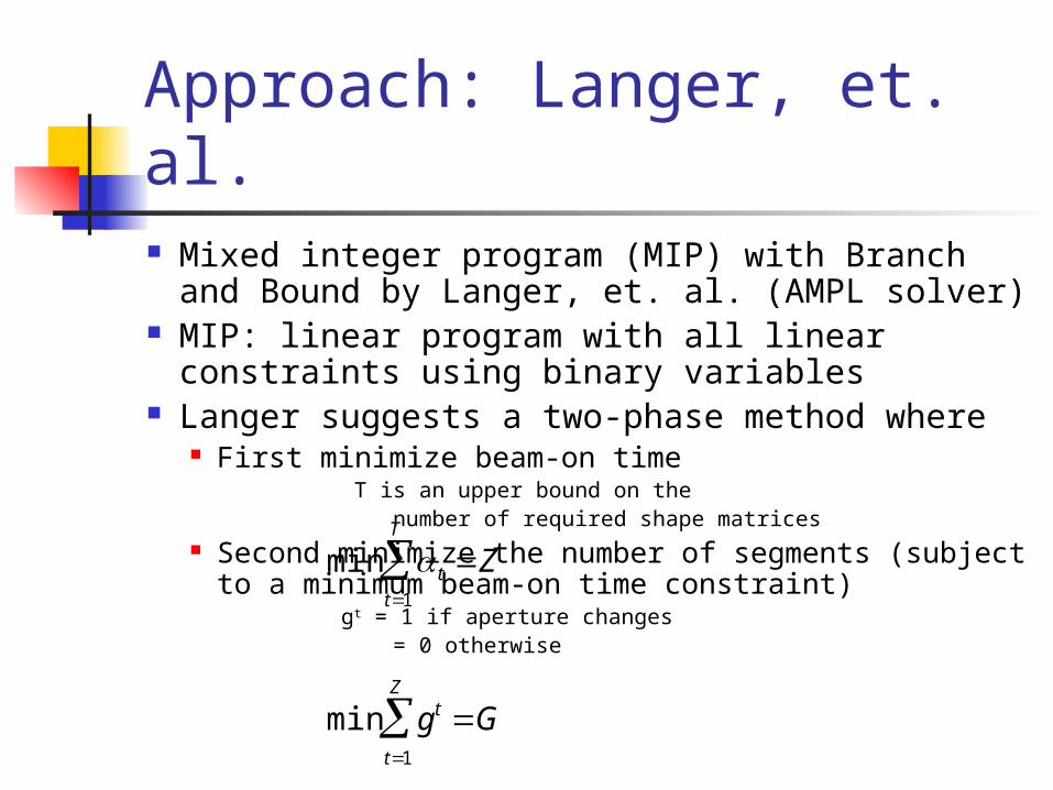
Approach: Langer, et. al. Mixed integer program (MIP) with Branch and Bound
by Langer, et. al. (AMPL solver) MIP: linear program with all linear constraints using
binary variables Langer suggests a two-phase method where
First minimize beam-on time T is an upper bound on the number of required shape matrices
Second minimize the number of segments (subject to a minimum beam-on time constraint)
gt = 1 if aperture changes = 0 otherwise
min t Zt1
T
min gt Gt1
Z
In Practice Langer, et. al. do not report times and we have found
that computing times are impractical for many real applications.
To obtain a balance between the need for a small number of shape matrices and a low beam-on time we seek to minimize
numShapeMatrices*7 + beam-on time
Initializing T close to the optimal number of matrices + 1 required reduces the solution space and solution time
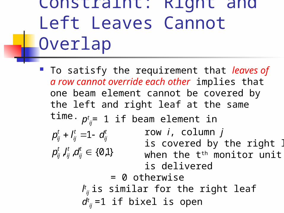
Constraint: Right and Left Leaves Cannot Overlap To satisfy the requirement that leaves of a row
cannot override each other implies that one beam element cannot be covered by the left and right leaf at the same time.
pijt lij
t 1 dijt
pijt , lij
t ,dijt {0,1}
ptij= 1 if beam element in
row i, column j is covered by the right leaf when the tth monitor unit is delivered = 0 otherwiselt
ij is similar for the right leafdt
ij =1 if bixel is open

Constraint: Full Leaves and Intensity Matrix Requirements Every element between the leaf end and
the side of the collimator is also covered (no holes in leaves).
pijt pij1
t
lij1t lij
t0 1 0 1 0 0
NON-CONTIGUOUS
shape matrix:
leaf setting:0 1 1 1 0 0
CONTIGUOUS
shape matrix:
leaf setting:
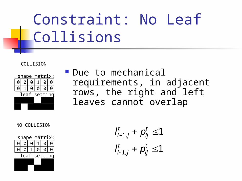
Constraint: No Leaf Collisions
Due to mechanical requirements, in adjacent rows, the right and left leaves cannot overlap
0 0 0 1 0 00 1 0 0 0 0
0 0 0 1 0 00 0 1 0 0 0
COLLISION
NO COLLISION
shape matrix:
leaf setting:
shape matrix:
leaf setting:
li1, jt pij
t 1
li 1, jt pij
t 1

Accounting and Matching Constraints The total number of shape matrices used is tallied.
zt= 1 when at least one beam element is exposed
when the tth monitor unit in
the sequence is delivered
= 0 otherwise
I is the number of rows
J is the number of columns
dijt
j1
J
i1
I
z t I J
z {0,1}
Must sum to the intensity matrix.
is the intensity assigned to
beam element dtij
tdijt
t1
T
Aij
t

Constraint: MonoshapeNo rows gaps are allowed: monoshapes are required First determine which rows in each monitor unit are open to
deliver radiation
delivery it dijt delivery it
j1
Ncols
delivery {0,1}
deliveryit=1 if the ith row is being
used a time t
= 0 otherwise
Determine if the preceding row in the monitor unit delivers radiation
deliveryi 1,t deliveryit dropit
drop {0,1}
dropit=1 if the preceding row (i-1)
in a shape is non-zero
and the current row (i) is 0
= 0 otherwise

Constraint: Monoshape Determine when the monoshape ends
deliveryit delivery i 1,t jumpit
jump {0,1}
jumpit=1 if the preceding row (i-1)
in a shape is zero and the
current row (i) is nonzero
= 0 otherwise
There can be only one row where the monoshape begins and one row to end
jumpit 1i2
Nrows
dropit 1i2
Nrows
deliveryi1,t 1 dropIt
I 2
Nrows

Complexity of Problem
The complexity of the constraints results in a large number of variables and constraints.
type level Lowest Num Consts Avg Num Consts Largest Num Constsprostate 5 2178 2707 3267prostate 10 3889 4838 5841
head&neck 5 3257 3519 3695head&neck 10 5511 6231 6606head&neck 100 56555 64800 72012pancreas 5 5518 6432 6687pancreas 10 9112 10961 13839

Diff: Heuristic Fast heuristics use a difference matrix
Transformation: Given an mxn intensity matrix M, define the corresponding mx(n+1) difference matrix D Expand M by adding a column of zeros to the left
and to the right sides of M Define D row-wise by the differences: D(i, j)= M(i, j+1) - M(i, j)

Diff in Practice Variables:
Delta: generates difference matrix Count: counts nonzero rows Frequency(D,v): counts appearances of v or -v in matrix D
AlgorithmD = delta(M) // generate initial difference matrixwhile (count(D) > 0){
find d > 0 that maximizes frequency(D,d) // choose intensity dcall create_shape_matrix(S,d) // create shape matrix S
D= D - d*delta(S) // update the difference matrix}
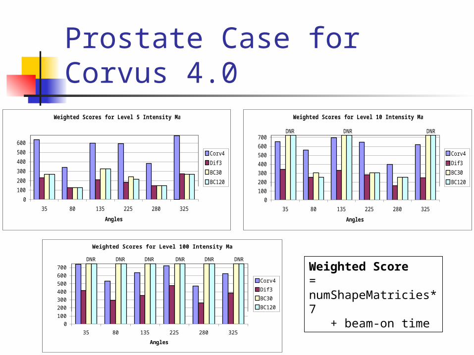
Comparison of Results: Prostate Case for Corvus 4.0
Weighted Score = numShapeMatricies*7 + beam-on time
Weighted Scores for Level 5 Intensity Maps
0
100
200
300
400
500
600
35 80 135 225 280 325
Angles
Wei
gh
ted
Sco
re Corv4
Dif3
BC30
BC120
Weighted Scores for Level 10 Intensity Maps
0
100
200
300
400
500
600
700
35 80 135 225 280 325
Angles
Wei
gh
ted
Sco
re Corv4
Dif3
BC30
BC120
DNR DNR DNR
Weighted Scores for Level 100 Intensity Maps
0100
200300400500
600700
35 80 135 225 280 325
Angles
Weig
hte
d S
core
Corv4
Dif3
BC30
BC120
DNR DNR DNRDNR DNRDNR

Comparison of Results: Head & Neck Case for Corvus 4.0
Weighted Score for Level 5 Intensity Maps
0
100
200
300
400
500
600
700
55 165 245 290 350
Angles
Wei
gh
ted
Sco
re Corv4
Dif3
BC30
BC120
DNR DNR
Weighted Score for Level 10 Intensity Maps
0
200
400
600
800
55 165 245 290 350
Angles
Weig
hte
d S
core Corv4
Dif3
BC30
BC120
DNRDNR
Weighted Score for Level 100 Intensity Maps
0100200300400500600700800
55 165 245 290 350
Angles
Weig
hte
d S
core Corv4
Dif3
BC30
BC120
DNR DNRDNR DNR DNR

Comparison of Results: Pancreas Case for Corvus 4.0
Weighted Score Level 5 Intensity Maps
0
200
400
600
800
1000
0 51 103 154 206 257 308
Angles
Weig
hte
d S
core Corv4
Dif3
BC30
BC120
DNR DNR DNR DNR DNR DNR DNR
Weighted Score Level 10 Intensity Maps
0
200
400
600
800
1000
0 51 103 154 206 257 308
Angles
Weig
hte
d S
core Corv4
Dif3
BC30
BC120
DNR DNR DNR DNR DNR DNR DNR
Weighted Score Level 100 Intensity Maps
0
200
400
600
800
1000
1200
0 51 103 154 206 257 308
Angles
Weig
hte
d S
core Corv4
Dif3
BC30
BC120
DNR DNR DNR DNR DNR DNR DNR

Future Work
Incorporate the Nested Partitions method into our shape matrix method to take advantage of randomized strategies.
Partition the more complicated shapes into two smaller shapes which can be handled quickly and easily. Then merge the resulting segments using the marriage algorithm to give a solution to the original problem.

Referenced Papers N. Boland, H. W. Hamacher, and F. Lenzen. “Minimizing beam-on time in cancer
radiation treatment using multileaf collimators.” Networks, 2002. T.R. Bortfeld, D.L. Kahler, T.J Waldron and A.L.Boyer, “X-ray field compensation
with multileaf collimators.” International Journal of Radiation Oncology Biology 28 (1994), pp. 723-730.
T. Bortfeld, et. al. “Current IMRT optimization algorithms: principles, potential and limitations.” Massachusetts General Hospital, Harvard Medical School, Presentation 2000.
D. Dink, S.Orcun, M. P. Langer, J. F. Pekny, G. V. Reklaitis, R. L. Rardin, “Importance of sensitivity analysis in intensity modulated radiation therapy (IMRT).” EuroInforms Presentation 2003.
K. Engel, “A new algorithm for optimal multileaf collimator field segmentation.” University Rostock, Germany, March 2003.
M. Langer, V. Thai, and L. Papiez, “Improved leaf sequencing reduces segments or monitor units needed to deliver IMRT using multileaf collimators.” Medical Physics, 28(12), 2001.
P. Xia, L. J. Verhey, “Multileaf collimator leaf sequencing algorithm for intensity modulated beams with multiple static segments.” Medical Physics, 25 (8), 1998.


