
A medieval clock made out of simple materialsmoloney/Ph425/ProjectPDFs/ejp_jul_08... · While the...
17
A medieval clock made out of simple materials This article has been downloaded from IOPscience. Please scroll down to see the full text article. 2008 Eur. J. Phys. 29 799 (http://iopscience.iop.org/0143-0807/29/4/013) Download details: IP Address: 137.112.34.173 The article was downloaded on 28/11/2008 at 21:32 Please note that terms and conditions apply. The Table of Contents and more related content is available HOME | SEARCH | PACS & MSC | JOURNALS | ABOUT | CONTACT US
-
Upload
trinhhuong -
Category
Documents
-
view
217 -
download
4
Transcript of A medieval clock made out of simple materialsmoloney/Ph425/ProjectPDFs/ejp_jul_08... · While the...

A medieval clock made out of simple materials
This article has been downloaded from IOPscience. Please scroll down to see the full text article.
2008 Eur. J. Phys. 29 799
(http://iopscience.iop.org/0143-0807/29/4/013)
Download details:
IP Address: 137.112.34.173
The article was downloaded on 28/11/2008 at 21:32
Please note that terms and conditions apply.
The Table of Contents and more related content is available
HOME | SEARCH | PACS & MSC | JOURNALS | ABOUT | CONTACT US

IOP PUBLISHING EUROPEAN JOURNAL OF PHYSICS
Eur. J. Phys. 29 (2008) 799–814 doi:10.1088/0143-0807/29/4/013
A medieval clock made out of simplematerials
B Danese and S Oss
Dipartimento di Fisica, Universita di Trento, Via Sommarive 14, 38100 Trento, Italy
E-mail: [email protected] and [email protected]
Received 4 April 2008, in final form 5 April 2008Published 16 June 2008Online at stacks.iop.org/EJP/29/799
AbstractA cheap replica of the verge-and-foliot clock has been built from simplematerials. It is a didactic tool of great power for physics teaching at everystage of schooling, in particular at university level. An account is given of itsconstruction and its working principles, together with motivated examples of afew activities.
(Some figures in this article are in colour only in the electronic version)
1. Introduction
Have you ever seen a medieval clock in action? It will look incredible to whom hasnever seen it, but from the rhythmic and continuous vibration of the daemon of thebalance beam, from the wriggling out of the escapement while every other part seemsimmobile, it springs such a sensation of living thing that one is enchanted. It is ashow one never grows tired to assist to: infinitely more suggestive than a swingingpendulum or than a rapidly beating modern clock. The world of humanities was inecstasy and struck with marvel.
So wrote Antonio Simoni in his massive work on the history of horology [1]. Not onlythe world of humanities was struck with marvel, as is evident from many accounts [2], but alsothe world of technology from which it stemmed. The mechanical clock has been regarded asa ‘turning point of western technology’ [3, 4] and the simple model here proposed, in fact,was developed in a course for middle school technology teachers. But most importantly, theweight-driven medieval clock with the verge-and-foliot escapement is a fascinating object forthe teaching of physics at various levels, from middle school to university.
While the potential of the pendulum clock for science and physics education has beenfully developed [5, 6], the educational value of the verge-and-foliot clock has been accountedfor mostly in the field of control theory [7–9] and history of science [10–12]. The main object
0143-0807/08/040799+16$30.00 c© 2008 IOP Publishing Ltd Printed in the UK 799

800 B Danese and S Oss
Figure 1. The driving-weight clock out of simple materials.
and novelty of this paper is to provide relevant examples of the use of the verge-and-foliotclock as a tool for physics education.
For instance, middle schools are the places where the clock can be built hands-on fromsimple materials and used for scientific explorations [13]. At middle school, clocks of manytypes [14] can be described by means of drawings and causal explanations, and can be used indiscussing energy and machines. At high school every topic of introductory mechanics—fromlevers to circular motions, from collisions to potential energy—finds an illustration in theclock. It allows many activities of data taking and data analysis to be carried out using simplechronometers and rulers. It is also a most interesting topic for the history of science and for avisit to a museum [15]. It is at the university level that a deepened didactic use of the clock maytake place. There the clock can be completely described by means of analytical mechanicswith the desired degree of approximation. More detailed experiments can be carried out bymeans of electronic sensors and automatic data acquisition, as is shown in this paper. In fact,the clock itself is an oscillator, useful to illustrate topics like feedback and limit cycles [7–9].
In this paper we describe the construction and the working principles of the clock, togetherwith motivated examples of a few activities to be carried out at various stages of schooling.The focal point of our perspective is university-level physics, thus the pre-university activitieswe present should be considered in this perspective.
2. Building and principle of operation
The verge-and-foliot escapement was an invention of radical originality. Thecomplexity of its functioning and the ingenuity with which it has been devised farsurpassed all previous mechanical inventions. Its characteristic feature, the carefullytuned dynamic interaction of several matching parts, is almost impossible to describein words or to illustrate in a two-dimensional picture; to fully comprehend it, oneshould handle a working specimen [10].

A medieval clock made out of simple materials 801
Hence, the need for a verge-and-foliot clock built from simple materials. Our workingmodel is shown in figure 1. It is built out of toothpicks, cardboard, a straw, a popsicle stick,sewing thread and a couple of screws. The frame is made with MeccanoTM pieces, but a pastabox or a shoe box would work as well. The operation of the mechanism is the following.
(a) The driving weight (here a film can with a few coins inside, but any small object ofappropriate mass may work as well) is suspended by sewing thread coiled around theshaft (a wooden skewer). At one end of the shaft, the crown or geared wheel (cardboarddisc) with its pegs (toothpicks) is pulled in rotation by the fall of the driving weight. Apeg of the crown strikes the upper palette (a popsicle stick piece) of the verge (a straw)and the motion of the wheel is checked by the inertia of the verge, the foliot (a woodenskewer) and the balance weights (pieces of key-holders).
(b) The driving weight slowly turns the verge and foliot until the peg has pushed the paletteout of the way (escapement) and the driving weight can, for a while, fall freely.
(c) The turning of the verge has, however, brought the lower palette between the pegs of thewheel so that the next lower peg, moving in the opposite direction to those on top, almostimmediately strikes the lower palette. The turning motion of foliot and balance weightsand the fall of the driving weight are thus slowed down.
(d) Once more a peg pushes the palette and the whole verge and foliot, but this time in theopposite direction so that the upper palette is brought back again into mesh with the pegsof the wheel.
The process then repeats itself until the driving weight reaches the ground, with the foliotand balance weights swinging to and fro.
2.1. The making of the clock or science and technology in middle school
Building such a device will give great satisfaction and many things to learn to students frommiddle school to university (and to their teachers too). The brilliancy of the mechanicalinsight that the motions in opposite directions of the upper and lower parts of the crown can beconverted into the cyclic to-and-fro motion of the verge and foliot will guide their reasoningon quantitative aspects of the phenomenon (see figure 2).
How many pegs are required in the crown, for instance? What about the angle betweenthe palettes? What about peg length and crown–verge distance? Different inquiry paths areopen: geometrical reasoning, building of a test model, replication of the clock built by theteacher, including its variations.
The technique of orthogonal projections—very common in Italian middle schools—canbe highly useful in this 3D reasoning. One discovers that if the number of pegs is even, theupper peg escaping from the upper palette would have a symmetrical lower peg pushing thelower palette in the opposite direction. This would block the clock, and one should choose anodd number of pegs, for example, five. The principle of operation is very well shown withfive pegs and the construction of a pentagon, moreover, is a very beautiful ‘ruler and compass’exercise.
The whole cause-and-effect analysis of the mechanism is stimulating for the student,as well as the recognition of dynamical principles embodied in the construction. The moststriking one is action–reaction: when crown pegs push the palettes and turn the verge, thenpalettes push the crown pegs, and the system shaft + crown + pegs slowly slides away fromthe verge. Therefore, a block to avoid the sliding of the shaft along its rotation axis is neededin the construction.
The clock builder also discovers the importance of the bond between crown and shaft,and will try to fix it with plastic tape, glue or plasticine. The student may also find profit in the

802 B Danese and S Oss
Figure 2. The kinematical insight of the verge-and-foliot clock: the motions in opposite directionsof the upper and lower parts of the crown can be converted into the cyclic to-and-fro motion of theverge and foliot.
device’s characterization with his own watch or chronometer and check the repeatability of itstic-tacks. This activity may be considered not only as a control of the performance, but also asthe calibration of an instrument, since different clocks may be arranged to beat the same time.
2.2. Simple models of the clock or high-school physics
In high-school physics the mechanical clock can be used at least in three important ways: (a)as an illustration or starting point for many topics connected with motion, (b) as a source forseveral ‘Kapitza problems’ [16] and (c) as a landmark for narrating the history of physics.
The topics for which the clock provides illustrations or starting points comprise thefollowing:
• Uniform, accelerated, circular and periodic motion. The motion of the driving weight, infact, keeps accelerating and stopping and time is divided in small equal units, which areeventually counted. However, the motion of the falling weight in a given time unit is notuniform. Crown pegs may also illustrate circular and harmonic motion.
• Focusing on balance weights; references can be made to levers, to pendulums of differentlengths, to angular momentum and torques. There is the typical example of opening thedoor far from or close to the door hinge. Other comparisons come from simple pendulumsand metronomes.
• Forces. Both external forces, like gravity pulling down the weight, and internal forces,like the tension in the string or the forces between peg and palette obviously have anessential role in the understanding of the clock.
• Collisions. The peg and palette hit each other, and their collision may be investigatedchanging the quantity of motion of the respective systems by means of the attached weight.One may therefore have a palette bouncing back or a palette pushing peg and wheel inthe opposite direction.
A medieval clock made out of simple materials 803
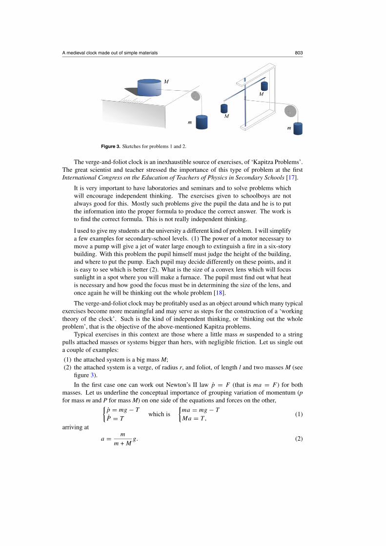
Figure 3. Sketches for problems 1 and 2.
The verge-and-foliot clock is an inexhaustible source of exercises, of ‘Kapitza Problems’.The great scientist and teacher stressed the importance of this type of problem at the firstInternational Congress on the Education of Teachers of Physics in Secondary Schools [17].
It is very important to have laboratories and seminars and to solve problems whichwill encourage independent thinking. The exercises given to schoolboys are notalways good for this. Mostly such problems give the pupil the data and he is to putthe information into the proper formula to produce the correct answer. The work isto find the correct formula. This is not really independent thinking.
I used to give my students at the university a different kind of problem. I will simplifya few examples for secondary-school levels. (1) The power of a motor necessary tomove a pump will give a jet of water large enough to extinguish a fire in a six-storybuilding. With this problem the pupil himself must judge the height of the building,and where to put the pump. Each pupil may decide differently on these points, and itis easy to see which is better (2). What is the size of a convex lens which will focussunlight in a spot where you will make a furnace. The pupil must find out what heatis necessary and how good the focus must be in determining the size of the lens, andonce again he will be thinking out the whole problem [18].
The verge-and-foliot clock may be profitably used as an object around which many typicalexercises become more meaningful and may serve as steps for the construction of a ‘workingtheory of the clock’. Such is the kind of independent thinking, or ‘thinking out the wholeproblem’, that is the objective of the above-mentioned Kapitza problems.
Typical exercises in this context are those where a little mass m suspended to a stringpulls attached masses or systems bigger than hers, with negligible friction. Let us single outa couple of examples:
(1) the attached system is a big mass M;(2) the attached system is a verge, of radius r, and foliot, of length l and two masses M (see
figure 3).
In the first case one can work out Newton’s II law p = F (that is ma = F ) for bothmasses. Let us underline the conceptual importance of grouping variation of momentum (pfor mass m and P for mass M) on one side of the equations and forces on the other,{
p = mg − T
P = Twhich is
{ma = mg − T
Ma = T ,(1)
arriving at
a = m
m + Mg. (2)

804 B Danese and S Oss
Table 1. Data for foliot lengths and time periods of complete rounds of the crown (10 tic-tacks).
Partial times of 10 tic-tacks (s)
Length l (cm) 10 20 30 40 Time (mean) t (s)
18.4 ± 0.1 13.71 27.44 41.08 54.92 13.7 ± 0.112.7 ± 0.1 9.68 19.25 28.66 38.06 9.5 ± 0.1
5.6 ± 0.1 3.88 7.93 11.70 15.46 3.9 ± 0.1
In the classroom the approximations on the friction of M (negligible), on the string(inextensible) and on the pulley (weightless) can be discussed after obtaining this result, sothat their bearing on the result may be readily shown. Friction, for example, may be added inthe equation and numerical tests for the justification of the approximation can be performed.
From the expression for the acceleration one may proceed to consider that the timenecessary for M to travel a fixed distance d is given by
t =√
2d
g
M + m
m. (3)
In the second case, to be coupled with p = F , one has the equation for the variation ofangular momentum of the verge and foliot:{
p = mg − T
L = τwhich is
{ma = mg − T12Ml2α = T r
and then
{ma = mg − T12Ml2a = T r2.
(4)
The accelerations are linked together by the consideration that α · r = a. Again one hasto solve a system of two equations with two unknowns, a and T. One obtains
a = m
m + M2
l2
r2
g that may be approximated with a ≈ 2mr2
Ml2g (5)
or
∝ ≈ 2mr
Ml2g. (6)
From the expression for the angular acceleration (6) one may obtain the time necessaryfor the foliot to cover a given angle θ :
t ≈ l
√θ
gr
M
m. (7)
The time interval necessary for turning the verge and foliot a given angle, while in squareroot relation with the mass ratio as before, is in linear relation with the foliot length. Therelation may be confronted with experiment. Measuring different times for varying lengthsof the foliot is very good for the topic of measurement, imprecision bars and basic statisticalanalysis. It can also be very good for checking the performance of the clock.
We present a set of simple data taken for different lengths of the foliot, by means of thechronometer of a mobile phone which allowed us to measure up to four partial times.
Three different foliot lengths, the corresponding raw data of the partial times of onecomplete round of the wheel (10 tic-tacks) along with the respective mean values, are shownin table 1. The data are plotted in figure 4. For clarity the uncertainty bars on the foliot lengthshave been propagated on the time axis. The relation between times and lengths is linear:
t = 0.73l. (8)

A medieval clock made out of simple materials 805
Figure 4. Plot of foliot lengths versus time intervals of complete rounds of the crown (10 tic-tacks).
Students are struck by the fact that a real clock can be built from scratch, and that itsregular behaviour (the linear relation between the time intervals and foliot lengths) can reallybe accounted for by means of formulae.
The ‘rough prediction’ plotted in figure 4 is estimated by means of equation (7) with thesubstitution of r with an effective radius r∗ from the interplay of the various gears:
r∗ = r0l0
rd
(9)
where r0 is the radius of the shaft, rd is the radius of the crown wheel and l0 is the distancebetween the verge axis and the end of the peg (see figure 5).
From the values and uncertainty bars of the various parameters θ , m, M, r∗ we obtainfor the constant in (8) the value of 0.50 s cm−1 (a range 0.41–0.59 s cm−1). The rathergross value may be refined taking into account the time needed to slow down the foliot atthe impact and the fact that acceleration is not constant, as is discussed later. We thus obtain0.78 s cm−1 for the constant in equation (8), and a predicted range of 0.70–0.86 s cm−1, ingood agreement with the experimental value of 0.73 s cm−1.
In this way, the construction and solution of several Kapitza problems lead to thecomprehension of various aspects of the working of the clock. Further problems, for example,may contain friction or gears and pulleys with different radii.
The point of view of mechanical work is also a very interesting one. While the suspendedweight falls, the shaft and the crown are slowly set in motion, and so are the verge and thefoliot with its balance weights. The energy of motion of the latter system is then convertedin halting with a collision of the crown and the falling weight. It is for this reason that theword feedback has been adopted in the description of this ancient clock, which has thus beencalled a double feedback clock. Thus, it happens that a key word of electronics characterizesa device whose origin is shrouded in mystery.
Once the clock has been explored quantitatively and modelled, its use in connection withthe history of science should seem very interesting at high-school level. The history of devices

806 B Danese and S Oss
Figure 5. Sketch of the clock (without foliot). The upper palette has just escaped at the angle θ = θE.
for the measurement of time was valued, for instance, by Thomas Young, who in his Lectureson Natural Philosophy and the Mechanical Arts [19] compiled a whole history of timekeeping.
Of the medieval clock, Young gave the following description:
The alternate motion of a balance, thrown backwards and forwards by the successiveactions of a wheel impelling its pallets, is also capable of producing a degree ofuniformity in the motion of the wheel; for the force operating on the pallet isconsumed in destroying a velocity in one direction and in generating a velocityin the contrary direction; and the space in which it acts being nearly the same in allcases, the velocity generated will also be nearly the same at all times, as long as theforce remains the same [19].
This beautiful mechanism had—according to Simoni [1]—been developed by ablacksmith or astrolabe-maker (the technology necessary for clock building was the onefor astrolabes building, mastered at the time) or monk (the first widespread use of mechanicalclocks was in monasteries), probably from armillary spheres and machines representing themotion of the heavenly spheres. This truly creative invention shows once more how in a truecultural outlook mechanical objects and the universal laws of mechanics are connected.
3. Clock description by means of classical mechanics
At university level the quantitative description of the whole clock can be undertaken as aproblem of analytical mechanics. The clock may be seen as composed by three moving bodiesconnected by two sets of internal forces, such three parts being
• the falling weight, of mass m, moving downwards with acceleration a;• the rotating crown + pegs + shaft, of inertia moment Id, covering the angle ϕ with angular
velocity ωd;• the oscillating verge + palettes + foliot + weights, of inertia moment I0, covering the angle
θ with angular velocity ω0.
The internal forces are
• T, the string tension which pulls up the weight m and torques the shaft (whose radius isr0);
• F, the force between the end of a peg and a palette.

A medieval clock made out of simple materials 807
Table 2. Data for foliot lengths, inertia moments, angular velocities and angular moments.
Length I0 (calculated) ωS (calculated) L0 (calculated) Ld (calculated)l (cm) (g cm2) (rad s−1) (g cm2 rad s−1) (g cm2 rad s−1)
18.4 1693 ± 18 1.65 ± 0.3 2794 ± 533 122 ± 2812.7 806 ± 13 2.4 ± 0.5 1929 ± 368 177 ± 40
5.6 157 ± 6 5.4 ± 1 850 ± 162 402 ± 91
3.1. Inertia moment
All the simplest moments of inertia are strikingly embodied in the verge-and-foliot clock,and the latter may serve as a beautiful introduction to the former. Moreover, the estimationof inertia moments involved in the clock is important for its description. One obtains Id =175 g cm2, I0 = 1693 g cm2 (at maximum foliot length, 806 and 157 g cm2 at inferior lengths,see table 2) where the momenta of inertia of a horizontal rod (foliot and palettes), a cylinder(shaft, crown and pegs), a hollow cylinder (verge) as well as the parallel axis theorem (forpegs and palettes) are employed.
3.2. Angle of escapement
In the tic-tacking of the clock we distinguish three phases:
• escapement, when the peg initially at rest pushes the upper palette from θ = 0 to θ = θE,(in which θE denotes the maximum angle before the peg leaves the upper palette, i.e. theescapement itself);
• free fly, when the foliot, once ‘escaped’, turns at constant speed and the crown freelyaccelerates until the lower palette impacts on the lower peg; we consider this phase aninstantaneous one;
• collision, the instantaneous impact in which kinetic energy of foliot and wheel areexchanged, and the following slowing down of wheel and foliot.
We begin with the analysis of the escapement phase and thus proceed to write a system ofthree equations in three unknowns, which is necessary for the description of a system of threemoving bodies:⎧⎨
⎩ma = mg − T
Idαd = T r0 − rdF cos θ cos ϕ
I0α0 = F l0/ cos θ.
(10)
Furthermore, the system is a connected mechanism and two relations between a, αd andα0 hold:
αd = a
r0(between a and αd); (11)
and the relation between αd and α0, which is more cumbersome:
αdrd cos ϕ = α0l0 or αd
√r2d − l2
0 tan2 θ = α0l0. (12)
From the geometrical relation between ϕ and θ ,
rd sin ϕ = l0 tan θ, (13)
one also obtains an expression for the foliot ‘arm’ l0 and the angle of escapement θE:
l0 = rd sinπ
5cotan θE. (14)

808 B Danese and S Oss
Thus, the wheel and shaft can be carefully placed so that l0 matches the actual anglebetween the palettes. In our case θE ≈ 70◦. However, our pegs are not very precise and theescapement takes place at angles between 70◦ and 50◦. We thus set l0 = 1.7 cm.
With the relations (11) and (12) one has now obtained the desired system of threeequations—corresponding to three objects—and three unknowns—corresponding to onedegree of freedom, a (or αd or α0), and the two internal forces T and F:⎧⎪⎪⎪⎪⎨
⎪⎪⎪⎪⎩
ma + T = mg
Id
r0a − r0T + rdF cos θ cos ϕ = 0
I0rd cos ϕ
r0a − l2
0
cos θF = 0.
(15)
3.3. The differential equation of the first escapement
Once the solution of (15) is found, from a one obtains
r0
rd
l0
cos ϕθ = g
r20 m
Id + r20 m + I0
r2d cos2 ϕ cos2 θ
l20
(16)
which can be greatly simplified if these approximations hold:
Id � I0r2d cos2 ϕ cos2 θ
l20
(17)
r20 m � I0
r2d cos2 ϕ cos2 θ
l20
(18)
cos ϕ ≈ 1. (19)
In fact, even in the worst case (the greatest values for ϕ and θ , ϕE = 36◦ and θE = 70◦),one has
mr20 ≈ 1.5,
r2d
l20
cos2 ϕE cos2 θE ≈ 5.5, cos ϕE ≈ 0.81. (20)
With the above-mentioned approximations, one obtains
θ = mgr0l0
I0rd cos2 θ. (21)
The various parameters can be summarized in the constant A of dimensions T−2:
A = gmr0l0
I0rd
. (22)
In our case, A = 1.5 ± 0.6 s−2, see table 3.The description of the escapement phase is therefore reduced to the Cauchy problem
θ = A
cos2 θ(23)
with initial conditions θ (0) = 0 and θ(0) = 0.Before undertaking its solution, let us ponder the plot of the function cos−2θ , which thus
also represents θ in units of A (figure 6). Thus, the whole problem may be approximated with
θ = A (24)

A medieval clock made out of simple materials 809
Figure 6. Plot of y = cos−2 θ . It is 2.5 at 50◦ and almost 10 at 70◦.
Table 3. Data for foliot lengths and angular accelerations, and times of one-round periods.
A 10tS AN 10tD 10tS + 10tD 10tLength (calculated) (calculated) (calculated) (calculated) (calculated) (measured)l (cm) (rad s−2) (s) (rad s−2) (s) (s) (s)
18.4 1.5 ± 0.3 10.8 ± 2.2 2.4 ± 0.5 6.8 ± 1.4 17.6 ± 3.6 13.7 ± 0.112.7 3.2 ± 0.6 7.4 ± 1.5 5 ± 1 4.7 ± 0.9 12.1 ± 2.4 9.5 ± 0.1
5.6 16.5 ± 3 3.3 ± 0.7 26 ± 5 2.0 ± 0.4 5.3 ± 1.1 3.9 ± 0.1
for small angles θ , that is, for a high number of pegs. While typical medieval clocks havecrowns with a high number of pegs, this is not our case. We must deal with equation (23).The first integration is easily achieved, and one obtains the angular velocity
ω0 =√
2A√
tan θ, (25)
that is, the Cauchy problem
θ =√
2A√
tan θ (26)
with the remaining initial condition θ(0) = 0.The integration of the latter is trickier but nonetheless exact and is
n−2 arctan(1 −√
2 tan θ) + 2 arctan(1 +√
2 tan θ)
+ ln
∣∣∣∣∣ tan θ +√
2 tan θ + 1
− tan θ +√
2 tan θ − 1
∣∣∣∣∣ = 4√
A t (27)
which we write as
F(θ) = 4√
At. (28)
We thus arrive at the desired expression t = t(θ ), from which we can obtain θ = θ (t).Before studying the latter, let us consider once more the approximation for small angles θ = A.It would follow
θ = At and θ = A
2t2. (29)

810 B Danese and S Oss
Figure 7. Plot of θ = θ (t) of the first escapement from equation (28) (continuous line) and fromequation (30) (dotted line).
The latter could be rewritten as
4√
2θ = 4√
At (30)
which compares very well with (28). The two functions (28) and (30) are plotted in figure 7as θ = θ (t).
It turns out, therefore, that even if the acceleration at wide angles is up to ten times itsinitial value, the discrepancy between the time of escapement in the two models is of the orderof only 6%. The approximated one may thus be safely used at high school level, since it yieldscompatible results.
3.4. Measurement of the first escapement with electronic acquisition
Electronic acquisition allows us to measure the rotation of the foliot and verify equation (28)plotted in figure 7. We use the Pasco Rotary Motion Sensor RMS-BTD mechanically coupledwith the verge . A new set of data is acquired in the new configuration. Oscillations are slower(the fit gives t = 0.95l) by a factor of 1.29 (see figure 8).
The two estimations in figure 7 need therefore to be rescaled by the same factor, 1.29.For examples, the foliot should now arrive at the angle θ = 60◦ in 1.45 or 1.51 s, and not asbefore in 1.12 or 1.17 s.
We acquired the data of the first escapement with a resolution of 1440 divisions/rotationand a sampling rate of 200 Hz. The data are plotted in figure 9. The agreement between dataand theory is remarkable. We see that the escapement takes place at 58◦ and after the suddenimpact the motion of the foliot is slowed down with almost uniform acceleration.
An acquisition for a more prolonged time is plotted in figure 10. Single tic-tacks arevisible: the peaks are when the foliot is stopped by the lower palette and the bottoms are whenit is stopped by the upper palette. The different heights of these peaks are suggestive of themisalignments among the five pegs. However, the cycle of ten tic-tacks (five peaks and fivebottoms) is clearly visible.

A medieval clock made out of simple materials 811
Figure 8. Plot of time intervals of complete rounds of the crown versus foliot lengths (10 tic-tacks).
Figure 9. Plot of θ = θ (t) of the first escapement from equation (28) (continuous line) and fromequation (30) (dotted line).
Other information one can gather from these measurements is that the first escapement issomewhat slower than the successive ones, when the clock reaches its limit cycle.
3.5. The time interval of the first escapement
From inversion of (28) we obtain θ = θ (t), which is plotted in figures 7 and 9 together withthe approximated function from (30). For θ = θS one obtains the time of escapement tS,
tS = F(θS)
4√
A, (31)

812 B Danese and S Oss
Figure 10. Foliot angle acquired on-line with the Pasco rotary motion sensor.
or, within 6% accuracy,
tS ≈√
2θS/A, (32)
which is also consistent with equation (7), obtained in the simplified high-school Kapitzaproblem.
3.6. The collision
The correction to the time interval used in figure 3 takes into account the time in which thedriving weight and the crown stop the motion of the foliot after the escapement and the impact.Thus, one has to take into account the sudden drop due to the impact and the deceleration fromthis residual velocity to 0. As has been done so far, this question can be addressed by meansof Kapitsa problems or by a detailed analysis that can also be tested with data acquisition.
We confine ourselves to a few considerations, referred to the set of data in table 1, figure 4,discussed in section 2.2. In the case of the longest foliot, after the escapement the verge+foliotis turning with angular velocity ωS ≈ 95◦ s−1 (a value consistent with the data in figure 9). Itsangular moment, therefore, is
L0 ≈ I0ωS ≈ 2794 g cm2 rad s−1. (33)
The crown, once the peg has escaped, has an angular momentum
Ld ≈ Idωd ≈ 122 g cm2 rad s−1. (34)
In the simplest approximation we thus regard as unchanged the angular velocity of thefoliot just after the impact with the peg. The correction to the time interval is therefore mainlydue to the deceleration, when the foliot pushes the crown backwards. In this case the efficientradius is not like equation (9): instead of the partial arm l0 (in our case 1.7 cm), where the pegpushes the palette, one has to take into account l1 (in our case 2.7 cm), the whole length of thepalette that is pushing the peg:
r∗ = r0l1
rd
. (35)
A medieval clock made out of simple materials 813
The calculated times are shown in table 3. The estimation of one-round period sums upten time intervals due to escapement tS and ten time intervals due to deceleration tD. The valueis slightly higher than that actually measured, the real clock goes quicker than the modelledone. This could be taken into account using the exact F(θ ) from (27), which reduces tS by5–6%, as is done in figure 4. The discrepancy may be further reduced taking into account thefact that ω of the foliot is diminished by the impact with the peg, which reduces tD by 6–60%according to the length of the foliot.
4. Conclusion
We have shown the didactic utility of a mechanical clock made out of simple materials. Itmay be used in different ways according to the level of school, but in particular at university.It can be used in countless ways and for countless exercises.
We had fun in letting the suspended weight travel down for three floors. However, furtherimprovements can still be made to our simple mechanism. First of all, the addition of morewheels and a hand. The wheel with pegs could be re-shaped and imitate the original medievalcrown, with its characteristic teeth, which may be considered as the link between gears madeof pegs and modern gears.
Of course, the teacher may also elaborate on the metaphor of the world as a clock, andits many examples in the literature. However, from the cultural point of view, we are contentto underline that the clock allows us to use the word mechanics in both its meanings, that ofmathematical physics and that of gears and shafts, together.
Acknowledgments
We would like to thank the group of technology teachers for their participation in the activityand useful observations.
References
[1] Simoni A 1965 Orologi italiani dal Cinquecento all’Ottocento (Milano: Vallardi)[2] Scattergood J 2003 Writing the clock: the reconstruction of time in the late Middle Ages Eur. Rev. 11 453–74[3] Cardwell D S L 1972 Turning Points in Western Technology: A Study of Technology, Science, and History (New
York: Neale Watson Academic)[4] Bernstein D S 2002 Feedback control: an invisible thread in the history of technology IEEE Control Syst.
Mag. 22 53–68[5] Matthews M R 2000 Time for Science Education: How Teaching the History and Philosophy of Pendulum Motion
can Contribute to Science Literacy Innovations in Science Education and Technology (Berlin: Springer)[6] Denny M 2002 The pendulum clock: a venerable dynamical system Eur. J. Phys. 23 449–58[7] Lepschy A M, Mian G A and Viaro U 1992 Feedback control in ancient water and mechanical clocks IEEE
Trans. Educ. 35 3–10[8] Roup A V, Bernstein D S, Nersesov S G, Haddad W M and Chellaboina V 2001 Limit cycle analysis of the
verge and foliot clock escapement using impulsive differential equations and Poincare maps Am. ControlConf. Proc. 2001 vol 4 pp 3245–50 doi: 10.1109/ACC.2001.946422
[9] Andronov A A, Vitt A A and Khaikin S E 1966 Theory of Oscillators (Oxford: Pergamon) (Reprinted by NewYork: Dover, 1987)
[10] Mayr O 1986 Authority, Liberty & Automatic Machinery in Early Modern Europe Johns Hopkins Studies in theHistory of Technology (Baltimore, MD: Johns Hopkins University Press)
[11] Jaki S L 1993 Medieval Christianity: its inventiveness in technology and science Technology in the WesternPolitical Tradition ed J Weinberger, A M Melzer and M R Zinman (Ithaca, NY: Cornell University Press)pp 46–68
[12] Dohrn-van Rossum G 1998 History of the Hour: Clocks and Modern Temporal Orders (Chicago, IL: Universityof Chicago Press)
[13] Doherty P 2005 Learning science by doing science with simple materials 3rd Int. GIREP Seminar 2005(Ljubljana)

814 B Danese and S Oss
[14] Zubrowski B 1988 Clocks: Building and Experimenting with Model Timepieces A Boston Children’s MuseumActivity Book (New York: William Morrow)
[15] A worldwide list of clock watch and time museums is available online at http://www.horology.com/ho-edmus.html
[16] Kapitsa P L 1977 Le Livre du Probleme de Physique (Paris: CEDIC)[17] Brown Sanborn C, Kedves F J and Wenham E J (ed) 1971 Teaching physics: an insoluble task? Proc Int.
Congress on the Education of Teachers of Physics in Secondary Schools (Eger, Hungary, September 1970)(Cambridge, MA: MIT Press)
[18] Kapitsa P L 1970 The general principles of the education of present-day youth and general methods of secondary-school physics teaching Proc. Int. Congress on the Education of Teachers of Physics in Secondary Schools(Eger, Hungary, September 1970) ed C Brown Sanborn, F J Kedves and E Wenham (Cambridge, MA: MITPress)
[19] Young T 1807 A Course of Lectures on Natural Philosophy and the Mechanical Arts (London: Taylor andWalton) (New edition 1845)