Optical Readout and Control Interface for the BTeV Pixel Vertex Detector
A MAPS based pixel vertex detector for the STAR experiment
39
L. Greiner LBNL instrumentation seminar, August 29, 2012 STAR HFT STAR HFT LBNL Leo Greiner, Eric Anderssen, Thorsten Stezelberger, Joe Silber, Xiangming Sun, Michal Szelezniak, Chinh Vu, Howard Wieman UTA Jerry Hoffman, Jo Schambach IPHC Strasburg Marc Winter CMOS group A MAPS based pixel vertex detector for the STAR experiment
Transcript of A MAPS based pixel vertex detector for the STAR experiment

L. Greiner 1LBNL instrumentation seminar, August 29, 2012
STAR HFTSTAR HFT
LBNLLeo Greiner, Eric Anderssen,
Thorsten Stezelberger, Joe Silber, XiangmingSun, Michal Szelezniak, Chinh Vu,
Howard Wieman
UTAJerry Hoffman, Jo Schambach
IPHC StrasburgMarc Winter CMOS group
A MAPS based pixel vertex detector for the STAR experiment
2LBNL instrumentation seminar, August 29, 2012L. Greiner
STAR HFTTalk Outline
• STAR detector upgrades at RHIC.
• Pixel detector requirements, design and characteristics.
• Detector development and prototyping flow path and status.o Emphasis on sensors and ladders
• Summary and plans.
The primary focus of this talk is technical and on instrumentation.
3LBNL instrumentation seminar, August 29, 2012L. Greiner
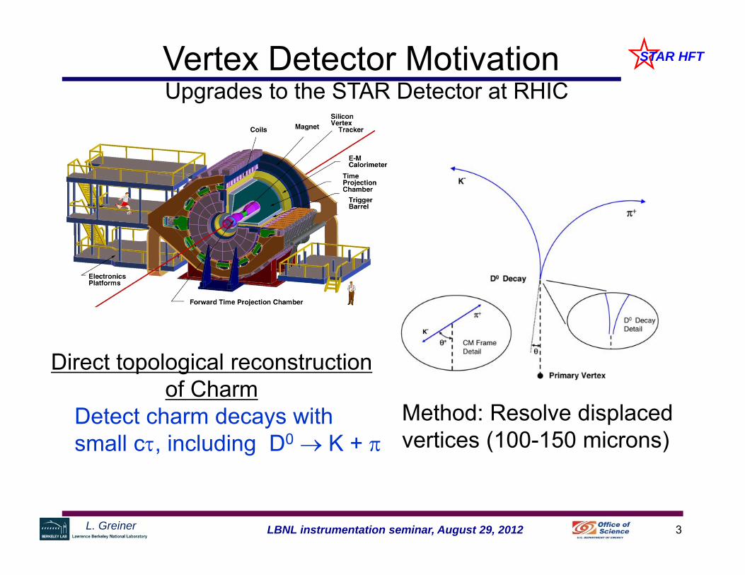
STAR HFTVertex Detector Motivation
Direct topological reconstruction of Charm
Detect charm decays with small c, including D0 K +
Method: Resolve displaced vertices (100-150 microns)
Upgrades to the STAR Detector at RHIC

4LBNL instrumentation seminar, August 29, 2012L. Greiner
STAR HFTPXL in Inner Detector Upgrades
TPC – Time Projection Chamber(main tracking detector in STAR)
HFT – Heavy Flavor Tracker SSD – Silicon Strip Detector
r = 22 cm IST – Inner Silicon Tracker
r = 14 cm PXL – Pixel Detector
r = 2.5, 8 cm
We track inward from the TPC with graded resolution:
TPC SSD IST PXL~1mm ~300µm ~250µm vertex<30µm

5LBNL instrumentation seminar, August 29, 2012L. Greiner
STAR HFTPXL Detector Requirements and Design Choices
• -1 ≤ Eta ≤ 1, full Phi coverage (TPC coverage)• ≤ 40 µm DCA pointing resolution required for 750 MeV/c kaon
– Two or more layers with a separation of > 5 cm.– Pixel size of ≤ 30 µm– Radiation length as low as possible but should be ≤ 0.5% / layer (including
support structure). The goal is 0.37% / layer• Integration time of < 200 μs• Sensor efficiency ≥ 99% with accidental rate ≤ 10-4.• Survive radiation environment.• Upgrade detector – fit into existing STAR infrastructure (trigger, DAQ, etc.)
• Air cooling• Thinned silicon sensors (50 μm thickness)• MAPS (Monolithic Active Pixel Sensor) pixel technology
– Sensor power dissipation ~170 mW/cm2
– Sensor integration time <200 μs (L=8×1027)• Quick extraction and detector replacement (1 day)
Req
uire
men
tsD
esig
n C
hoic
es
6LBNL instrumentation seminar, August 29, 2012L. Greiner
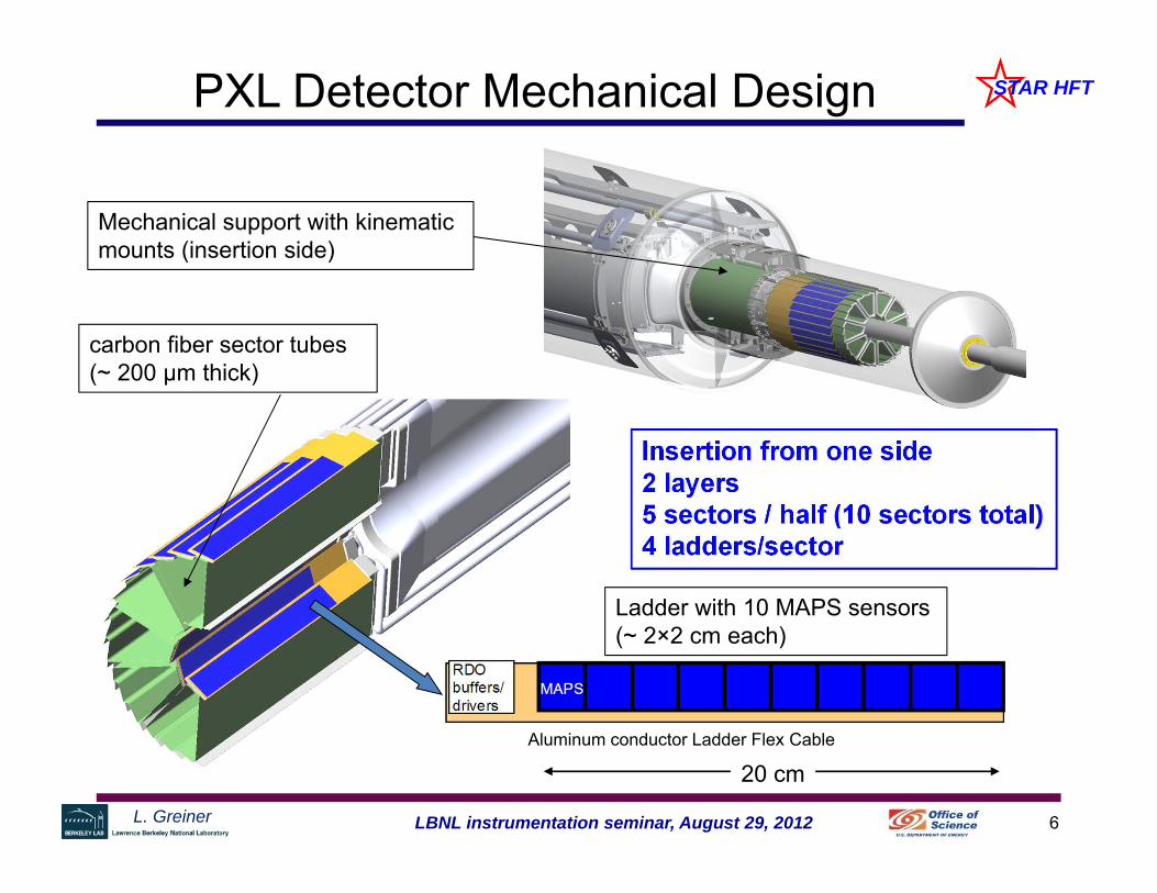
STAR HFTPXL Detector Mechanical Design
Mechanical support with kinematic mounts (insertion side)
Insertion from one side2 layers5 sectors / half (10 sectors total)4 ladders/sector
Aluminum conductor Ladder Flex Cable
Ladder with 10 MAPS sensors (~ 2×2 cm each)
carbon fiber sector tubes (~ 200 µm thick)
20 cm

7LBNL instrumentation seminar, August 29, 2012L. Greiner
STAR HFT
2 m (42 AWG TP)6 m (24 AWG TP)
100 m (fiber optic)
Highly parallel system
4 ladders per sector 1 Mass Termination Board (MTB) per sector 1 sector per RDO board 10 RDO boards in the PXL system
RDO motherboard w/ Xilinx Virtex-6 FPGA
DAQ PC with fiberlink to RDO board
Mass Termination Board (signal buffering) + latch-up protected power
PXL Detector Basic Unit (RDO)
Clk, config, data, powerClk, config, data
PXL built events
Trigger,Slow control,Configuration,etc.
8LBNL instrumentation seminar, August 29, 2012L. Greiner
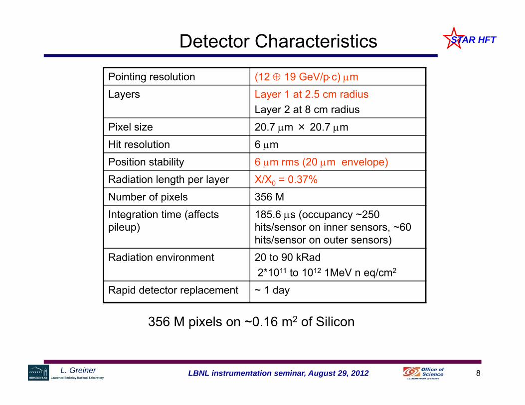
STAR HFTDetector Characteristics
Pointing resolution (12 19 GeV/pc) mLayers Layer 1 at 2.5 cm radius
Layer 2 at 8 cm radiusPixel size 20.7 m × 20.7 m Hit resolution 6 mPosition stability 6 m rms (20 m envelope)Radiation length per layer X/X0 = 0.37%Number of pixels 356 MIntegration time (affects pileup)
185.6 s (occupancy ~250 hits/sensor on inner sensors, ~60 hits/sensor on outer sensors)
Radiation environment 20 to 90 kRad2*1011 to 1012 1MeV n eq/cm2
Rapid detector replacement ~ 1 day
356 M pixels on ~0.16 m2 of Silicon

9LBNL instrumentation seminar, August 29, 2012L. Greiner
STAR HFTPXL Detector Production Path (post CD – 2/3)
Sensor development
Readout development
Mechanical development
Cable development
Pre-production prototype
UltProbe tests
Infrastructure development
Ult sensorprototype
10 sensorCu+kaptonpre-prod
Eng run Sector
prototype
Final Ladder readout
Final individual readout
Update mech for
size
Prod readout
production sensors
ProdProbe tests
10 sensorAl+kapton
prod
prod Sector
Eng run detector
prod detector
Dec 2012
Aug 2013
Culmination of 5 years of development
10LBNL instrumentation seminar, August 29, 2012L. Greiner
STAR HFT
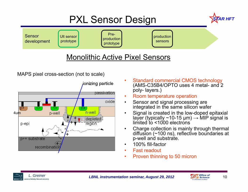
Monolithic Active Pixel Sensors
• Standard commercial CMOS technology(AMS-C35B4/OPTO uses 4 metal- and 2 poly- layers.)
• Room temperature operation• Sensor and signal processing are
integrated in the same silicon wafer• Signal is created in the low-doped epitaxial
layer (typically ~10-15 μm) → MIP signal is limited to <1000 electrons
• Charge collection is mainly through thermal diffusion (~100 ns), reflective boundaries at p-well and substrate.
• 100% fill-factor • Fast readout• Proven thinning to 50 micron
MAPS pixel cross-section (not to scale)
PXL Sensor Design
4um
Sensor development
Pre-production prototype
Ult sensorprototype
production sensors

11LBNL instrumentation seminar, August 29, 2012L. Greiner
STAR HFTSensor generation and RDO attributes
Pixel
Sensors CDS
ADC Data
sparsification
readout
to DAQ
analogsignals
Complementary detector readout
MimoSTAR sensors 4 ms integration time
PXL final sensors (Ultimate) < 200 μs integration time
analog
digital digital signals
Disc.
CDS
Phase-1 sensors 640 μs integration time
Sensor and RDO Development Path
Develop sensor chips, 3 generation programSensors are designed by Marc Winter’s group at IPHC.
1
2
3Gen
erat
ion
12LBNL instrumentation seminar, August 29, 2012L. Greiner
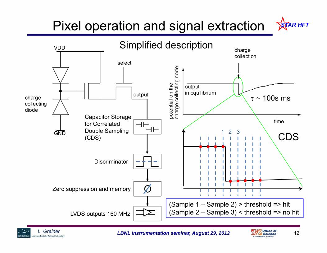
STAR HFTPixel operation and signal extraction
GND
VDD
select
outputoutputin equilibrium
time
pote
ntia
l on
the
char
ge c
olle
ctin
g no
de
chargecollection
chargecollectingdiode
Capacitor Storage for Correlated Double Sampling (CDS)
~ 100s ms
Discriminator
Zero suppression and memory
LVDS outputs 160 MHz
1 2 3
(Sample 1 – Sample 2) > threshold => hit(Sample 2 – Sample 3) < threshold => no hit
CDS
Simplified description
O
13LBNL instrumentation seminar, August 29, 2012L. Greiner
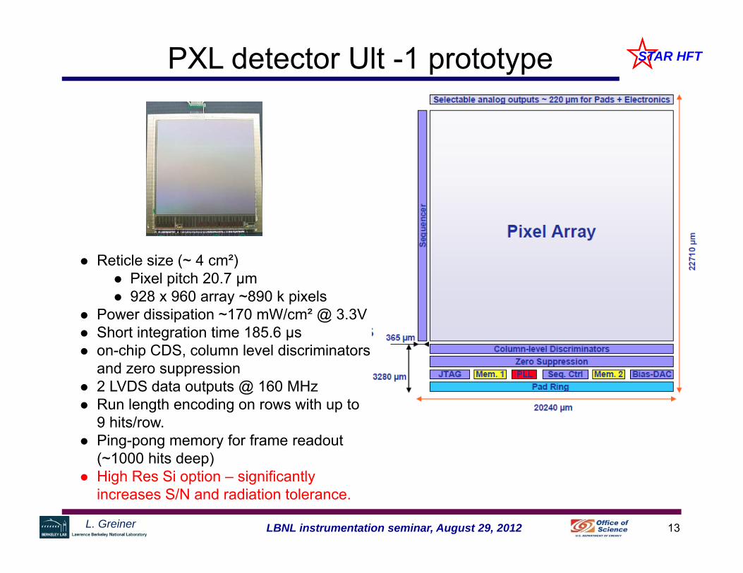
STAR HFTPXL detector Ult -1 prototype
Reticle size (~ 4 cm²) Pixel pitch 20.7 μm 928 x 960 array ~890 k pixels
Power dissipation ~170 mW/cm² @ 3.3V Short integration time 185.6 μs on-chip CDS, column level discriminators
and zero suppression 2 LVDS data outputs @ 160 MHz Run length encoding on rows with up to
9 hits/row. Ping-pong memory for frame readout
(~1000 hits deep) High Res Si option – significantly
increases S/N and radiation tolerance.

14LBNL instrumentation seminar, August 29, 2012L. Greiner
STAR HFTUltimate 1 efficiency vs. fake hit rate
Tested for STAR Operating conditions
Developed and tested by IPHC
Marc WinterCMOS GroupIPHC, Strasbourg, France

15LBNL instrumentation seminar, August 29, 2012L. Greiner
STAR HFTPXL Sensor Status
• Prototype PXL sensors (Ultimate 1) were tested at CERN test beam facility using a prototype PXL RDO system. The IPHC measured efficiency and accidental rate were reproduced. The sensors are functionally acceptable for engineering run use.
• Next generation Ultimate 2 has been submitted for fabrication (minor fixes and improvements).
• We have procured, diced and thinned 11 wafers of Ultimate 1 sensors. The mechanical dicing / thinning yield was 93%. These sensors will be used for the engineering run detector.
Sensor development
Pre-production prototype
Ult sensorprototype
production sensors
16LBNL instrumentation seminar, August 29, 2012L. Greiner
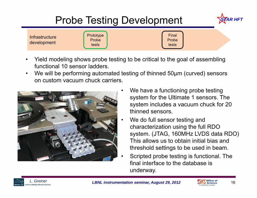
STAR HFTProbe Testing Development
• We have a functioning probe testing system for the Ultimate 1 sensors. The system includes a vacuum chuck for 20 thinned sensors.
• We do full sensor testing and characterization using the full RDO system. (JTAG, 160MHz LVDS data RDO) This allows us to obtain initial bias and threshold settings to be used in beam.
• Scripted probe testing is functional. The final interface to the database is underway.
Prototype Probe tests
Final Probe tests
Infrastructure development
• Yield modeling shows probe testing to be critical to the goal of assembling functional 10 sensor ladders.
• We will be performing automated testing of thinned 50µm (curved) sensors on custom vacuum chuck carriers.
17LBNL instrumentation seminar, August 29, 2012L. Greiner
STAR HFTRead-out Electronics
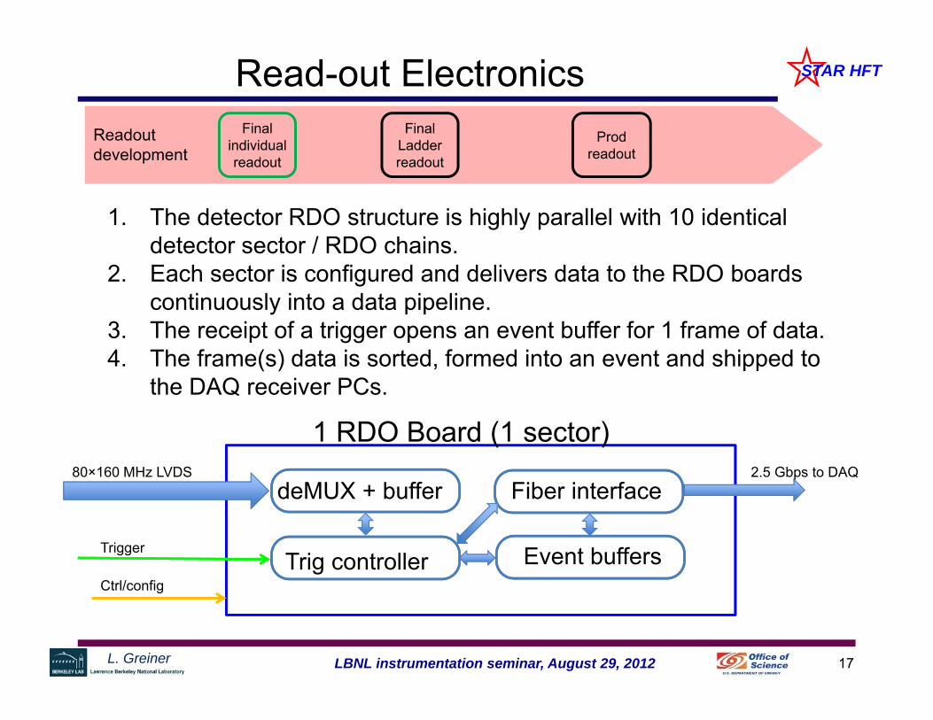
1. The detector RDO structure is highly parallel with 10 identical detector sector / RDO chains.
2. Each sector is configured and delivers data to the RDO boards continuously into a data pipeline.
3. The receipt of a trigger opens an event buffer for 1 frame of data.4. The frame(s) data is sorted, formed into an event and shipped to
the DAQ receiver PCs.
Readout development
Final Ladder readout
Final individual readout
Prod readout
80×160 MHz LVDS
Trigger
Ctrl/config
deMUX + buffer
Event buffersTrig controller
Fiber interface2.5 Gbps to DAQ
1 RDO Board (1 sector)
18LBNL instrumentation seminar, August 29, 2012L. Greiner
STAR HFTRead-out Electronics
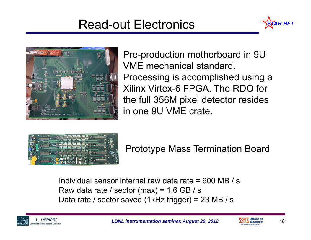
Individual sensor internal raw data rate = 600 MB / sRaw data rate / sector (max) = 1.6 GB / sData rate / sector saved (1kHz trigger) = 23 MB / s
Pre-production motherboard in 9U VME mechanical standard. Processing is accomplished using a Xilinx Virtex-6 FPGA. The RDO for the full 356M pixel detector resides in one 9U VME crate.
Prototype Mass Termination Board
19LBNL instrumentation seminar, August 29, 2012L. Greiner
STAR HFTCable Development
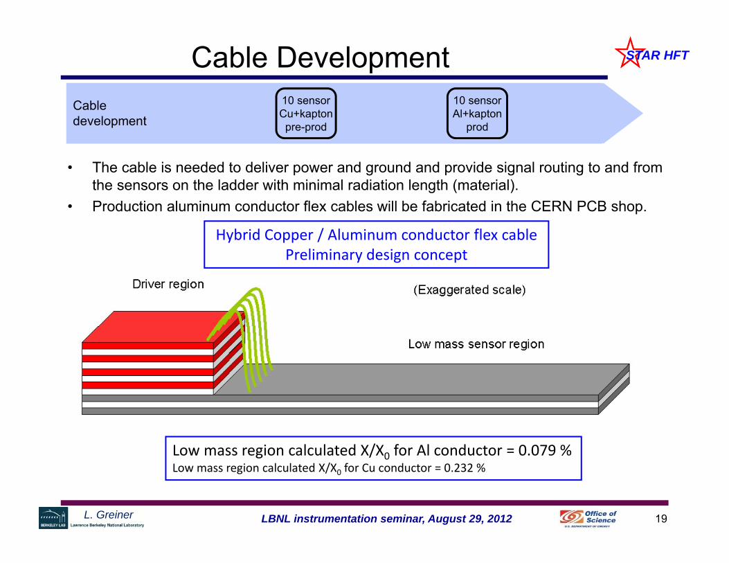
• The cable is needed to deliver power and ground and provide signal routing to and from the sensors on the ladder with minimal radiation length (material).
• Production aluminum conductor flex cables will be fabricated in the CERN PCB shop.
Cable development
10 sensorCu+kaptonpre-prod
10 sensorAl+kapton
prod
Low mass region calculated X/X0 for Al conductor = 0.079 %Low mass region calculated X/X0 for Cu conductor = 0.232 %
Hybrid Copper / Aluminum conductor flex cablePreliminary design concept
20LBNL instrumentation seminar, August 29, 2012L. Greiner
STAR HFTRadiation Length of active area
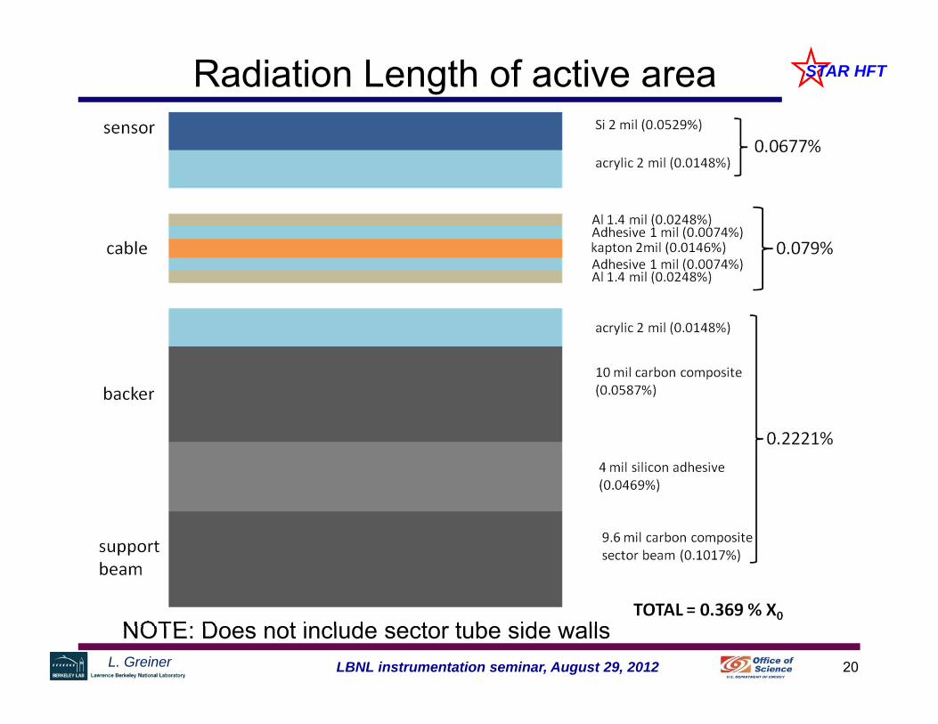
NOTE: Does not include sector tube side walls
21LBNL instrumentation seminar, August 29, 2012L. Greiner
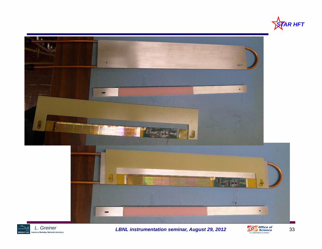
STAR HFTCable Development
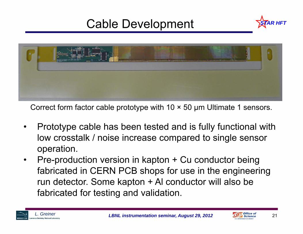
Correct form factor cable prototype with 10 × 50 µm Ultimate 1 sensors.
• Prototype cable has been tested and is fully functional with low crosstalk / noise increase compared to single sensor operation.
• Pre-production version in kapton + Cu conductor being fabricated in CERN PCB shops for use in the engineering run detector. Some kapton + Al conductor will also be fabricated for testing and validation.
22LBNL instrumentation seminar, August 29, 2012L. Greiner
STAR HFTSensors on ladders
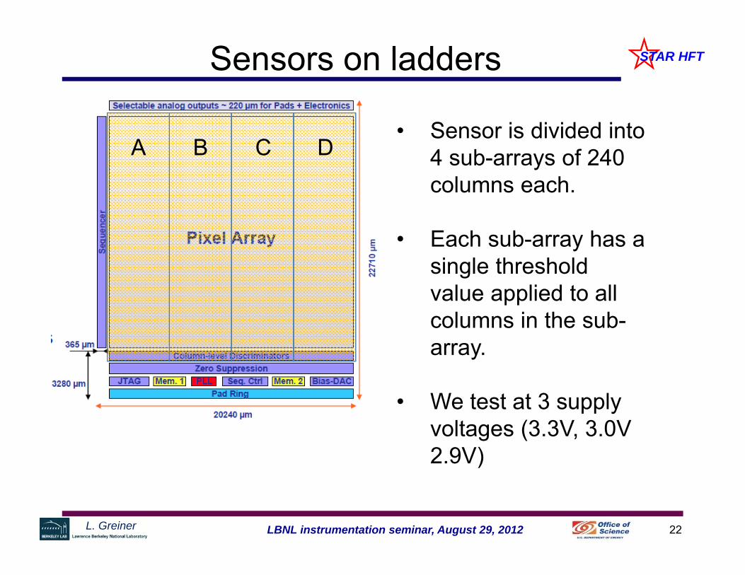
• Sensor is divided into 4 sub-arrays of 240 columns each.
• Each sub-array has a single threshold value applied to all columns in the sub-array.
• We test at 3 supply voltages (3.3V, 3.0V 2.9V)
A B C D
23LBNL instrumentation seminar, August 29, 2012L. Greiner
STAR HFTExamples of failures
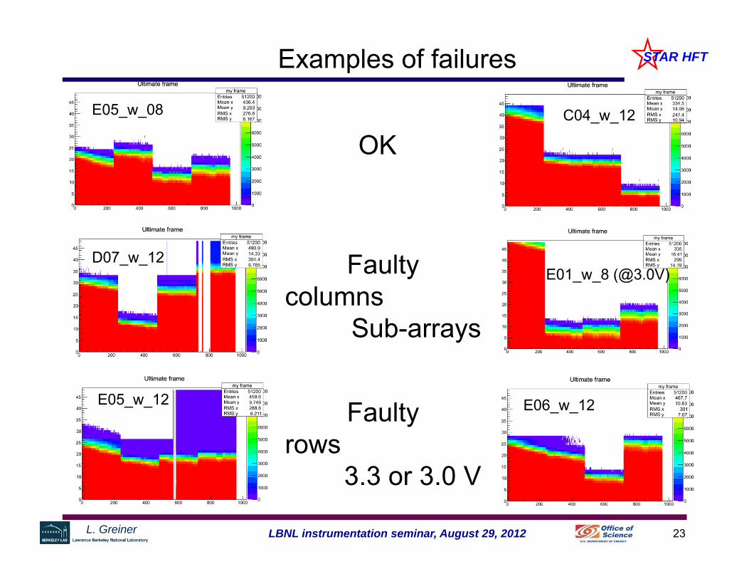
D07_w_12E01_w_8 (@3.0V)
E05_w_12 E06_w_12
E05_w_08 C04_w_12
OK
Faultycolumns
Sub-arrays
Faulty rows
3.3 or 3.0 V

24LBNL instrumentation seminar, August 29, 2012L. Greiner
STAR HFTLadder L1 measured noise
• High thresholds ~ standard operating condition (60-250 hit occupancy)
• Low thresholds ~ worst possible operating condition (full output activity – overflow on memories)
Dead sensor

25LBNL instrumentation seminar, August 29, 2012L. Greiner
STAR HFTPXL Mechanical
• Meeting the stability requirement is a challenge (20µm)• The full PXL mechanical design, tooling, fixturing and
insertion mechanism are implemented in solid modeling CAD.
• Thermal distortion, vibration, and cooling simulations are complete.
• Mechanical test sectors have been assembled using the tooling and used for thermal and vibration testing.
• The thermal and vibration simulations have been verified on a mechanical model of the detector.
Mechanical development
Eng run Sector
prototype
Update mech for
size
prod Sector

26LBNL instrumentation seminar, August 29, 2012L. Greiner
STAR HFTMechanical Development
Silicon power: tested at 170 mW/cm2
(~ power of sunlight) 350 W total in the ladder region (Si +
drivers) At 10 m/s airflow ∆T is kept to ~10º C Vibration and translation is within
acceptable limits.
computational fluid dynamicssimulation
Air-flow based cooling system for PXL to minimize material budget.
Detector mockup to study cooling efficiency
ladder region
Power ~350 W Airflow 10.1 m/s
Thermal camera image of sector 1 (composite image):

27LBNL instrumentation seminar, August 29, 2012L. Greiner
STAR HFTMechanical Development

28LBNL instrumentation seminar, August 29, 2012L. Greiner
STAR HFT1.2.1 PXL Mechanical
• Most major PXL components are fabricated or in process. Full insertion and kinematic mount testing is now complete and the mechanical design is functional and has (thus far) met the required level of stability.
• The inner detector support system (CFC shells and mounts) have been fabricated and will be installed into the STAR detector in the next few weeks together with the new small radius beam pipe.
Mechanical development
Eng run Sector
prototype
Update mech for
size
prod Sector

29LBNL instrumentation seminar, August 29, 2012L. Greiner
STAR HFTSummary and plans
• The HFT upgrade for STAR is well advanced in design, we passed our DOE CD-2/3 review in September 2011 and full ladder production is beginning.
• The PXL detector simulations and prototyping indicate that we should be able to achieve a new standard in low radiation length vertex detectors.
• The STAR PXL detector will be the first MAPS based vertex detector used at a collider accelerator experiment.
• We expect to produce a several sector prototype detector for installation in the December 2012 run.
• The final PXL detector along with the rest of the HFT upgrades will be installed for the November 2013 run.

30LBNL instrumentation seminar, August 29, 2012L. Greiner
STAR HFT
• end

31LBNL instrumentation seminar, August 29, 2012L. Greiner
STAR HFT
Beam test hit pixeloccupancy per cluster
50k triggers
L. Greiner 32LBNL instrumentation seminar, August 29, 2012
STAR HFT
2 2
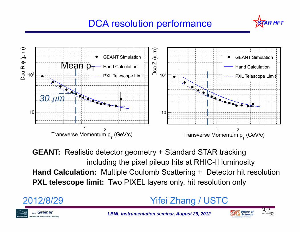
GEANT: Realistic detector geometry + Standard STAR trackingincluding the pixel pileup hits at RHIC-II luminosity
Hand Calculation: Multiple Coulomb Scattering + Detector hit resolutionPXL telescope limit: Two PIXEL layers only, hit resolution only
Mean pT
30 m
DCA resolution performance
322012/8/29 Yifei Zhang / USTC
L. Greiner 33LBNL instrumentation seminar, August 29, 2012
STAR HFT

34LBNL instrumentation seminar, August 29, 2012L. Greiner
STAR HFTRead-out Electronics
• The Xilinx Virtex-6 based RDO system motherboard has completed testing and is performing as designed.
• This board + prototype MTB were used for RDO for the Ultimate 1 prototype ladder testing.
• Based on this testing, the current RDO motherboards are the production prototype. We have placed the order for the 10 motherboards to be used in the engineering run.
• The RDO system is ahead of schedule.
Readout development
Final Ladder readout
Final individual readout
Prod readout
35LBNL instrumentation seminar, August 29, 2012L. Greiner
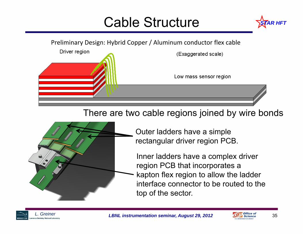
STAR HFTCable StructurePreliminary Design: Hybrid Copper / Aluminum conductor flex cable
There are two cable regions joined by wire bonds
Outer ladders have a simple rectangular driver region PCB.
Inner ladders have a complex driver region PCB that incorporates a kapton flex region to allow the ladder interface connector to be routed to the top of the sector.
36LBNL instrumentation seminar, August 29, 2012L. Greiner
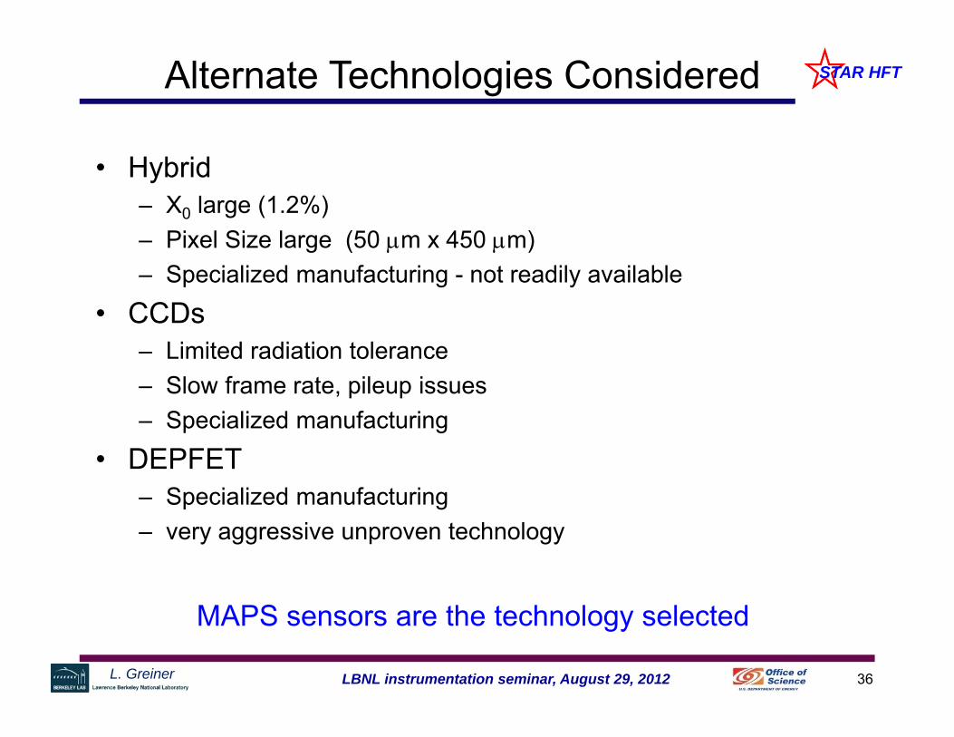
STAR HFTAlternate Technologies Considered
• Hybrid– X0 large (1.2%)– Pixel Size large (50 m x 450 m)– Specialized manufacturing - not readily available
• CCDs– Limited radiation tolerance– Slow frame rate, pileup issues– Specialized manufacturing
• DEPFET– Specialized manufacturing– very aggressive unproven technology
MAPS sensors are the technology selected
37LBNL instrumentation seminar, August 29, 2012L. Greiner
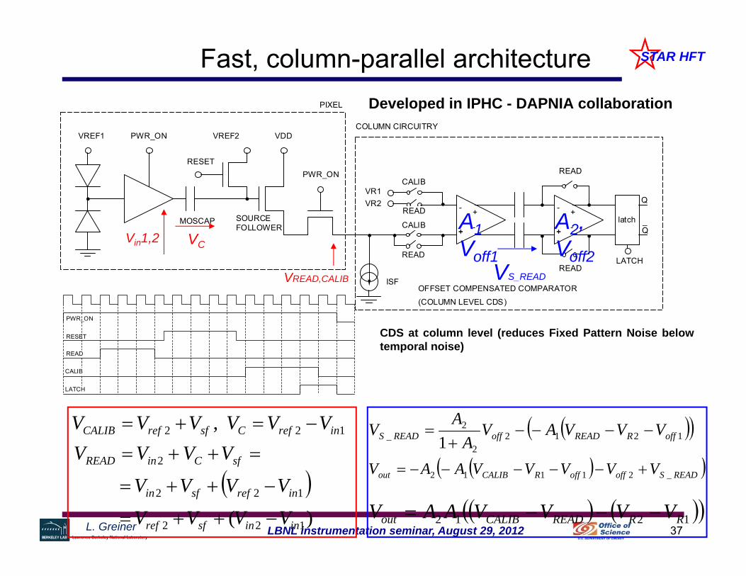
STAR HFTFast, column-parallel architecture
VREF1 PWR_ON
MOSCAP
RESET
VREF2 VDD
PWR_ON
VR1VR2
READ
CALIB
ISF
PIXEL
COLUMN CIRCUITRY
OFFSET COMPENSATED COMPARATOR
(COLUMN LEVEL CDS)
SOURCEFOLLOWER
latch
Q
Q_
READ
READ
+
+
+
+
+ +
-
- -
-
LATCH
CALIB
READ
PWR_ON
RESET
READ
CALIB
LATCH
CDS at column level (reduces Fixed Pattern Noise belowtemporal noise)
122 , inrefCsfrefCALIB VVVVVV
)( 122
122
2
ininsfref
inrefsfin
sfCinREAD
VVVV
VVVV
VVVV
VREAD,CALIB
VCVin1,2
12122
2_ 1 offRREADoffREADS VVVAV
AAV
READSoffoffRCALIBout VVVVVAAV _21112
1212 RRREADCALIBout VVVVAAV
VS_READ
A1 Voff1
A2, Voff2
Developed in IPHC - DAPNIA collaboration
38LBNL instrumentation seminar, August 29, 2012L. Greiner
STAR HFT
39LBNL instrumentation seminar, August 29, 2012L. Greiner
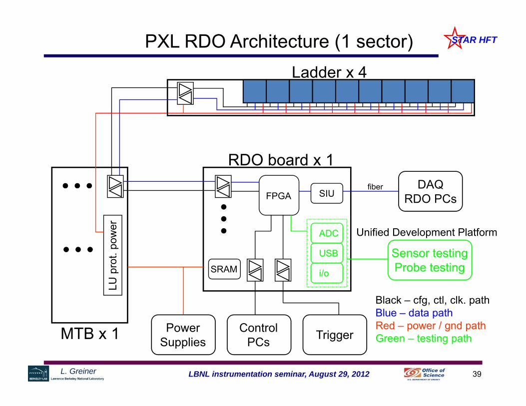
STAR HFTPXL RDO Architecture (1 sector)Ladder x 4
FPGA
LU p
rot.
pow
er
MTB x 1 PowerSupplies
ControlPCs Trigger
DAQRDO PCsSIU
ADC
USB
i/o
RDO board x 1
Sensor testingProbe testingSRAM
Black – cfg, ctl, clk. pathBlue – data pathRed – power / gnd pathGreen – testing path
fiber
Unified Development Platform