A low voltage “railgun”wierzba/amjphys/1.4760659.pdf · 2018-05-17 · g’s) does not change...
6
A low voltage “railgun” Stanley O. Starr and Robert C. Youngquist NASA, Mailstop NE-L5, KSC Applied Physics Lab, Kennedy Space Center, Florida 32899 Robert B. Cox QinetiQ North America, Mailstop ESC-55, Kennedy Space Center, Florida 32899 (Received 18 March 2012; accepted 2 October 2012) Due to recent advances in solid-state switches and ultra-capacitors, it is now possible to construct a “railgun” that can operate at voltages below 20 V. Railguns typically operate above a thousand volts, generating huge currents for a few milliseconds to provide thousands of g’s of acceleration to a small projectile. The low voltage railgun described herein operates for much longer time periods (tenths of seconds to seconds), has far smaller acceleration and speed, but can potentially propel a much larger object. The impetus for this development is to lay the groundwork for a possible ground-based supersonic launch track, but the resulting system may also have applications as a simple linear motor. The system would also be a useful teaching tool, requiring concepts from electrodynamics, mechanics, and electronics for its understanding, and is relatively straightforward to construct. V C 2013 American Association of Physics Teachers. [http://dx.doi.org/10.1119/1.4760659] I. INTRODUCTION Railguns have been studied and developed primarily as high-speed ballistic launchers for a variety of applications ranging from military weapons to space launchers. 1–4 Typi- cally, a high voltage capacitor bank is rapidly discharged (a few milliseconds) down a rail, across a sliding armature, and then up a return rail. The resulting current surge generates a large magnetic field and huge Lorentz forces across the ar- mature, accelerating it at thousands of g’s to speeds as high as 5.9 km/s. 1 Recent demonstrations are impressive: a 2010 Navy railgun test implies a projectile range of 110 miles, 2 inevitably leading to student interest in the operation and performance of these advanced linear motors. 5 Our interest at the Kennedy Space Center is not in the use of these devices as projectile launchers, but in the possibility that they can be used to construct a launch assist track. NASA studies have argued that future generation launch sys- tems, composed of an air breathing hypersonic vehicle launched off of a high speed rail, as depicted in Fig. 1, could substantially reduce the cost of placing payloads into earth orbit. 6–9 Significant advantages in airframe weight, engine type, and engine scale could be realized if this vehicle were launched from a ground based track at supersonic speeds (above Mach 1.2). Yet to date, most studies and prototype launch assist systems have proposed using linear synchro- nous motors 7 or linear induction motors, 9 neither of which appear to have been demonstrated at speeds above Mach 1 and which would be expensive to construct and operate. Given its relative simplicity and exceptional speed, this raises the question, “can railgun technology be used to launch a hypersonic air breathing vehicle?” Operating a railgun at relatively low acceleration (2 to 3 g’s) does not change the fundamental physics—current still flows through a closed circuit with a movable sliding armature—however, the time scale differs by orders of mag- nitude. So the name “railgun” is a misnomer in our applica- tion and we will instead use the name rail motor below. Also, the components needed to construct a rail motor are different from those used in a railgun, yet, fortuitously, the necessary items for the development of such a device have recently become available. In fact, a tabletop demonstration of a low-voltage, long time-constant rail motor has been built and operated and is described in this paper. Such a device both demonstrates that rail motor launch assist may be possi- ble and provides an interesting new motor that could be constructed as an upper-level class project. This paper begins by developing rail motor theory and is followed by a description of the tabletop motor we have con- structed. Special attention is given to the power supply design, as this is the new enabling entity that allows the rail motor to operate. Experimental results are then presented, followed by a section on safety issues. II. RAILGUN THEORY It is surprisingly difficult to find a clearly stated set of equations describing a railgun or rail motor in the literature. Many of the publications present an incomplete model with reference to prior railgun papers. Following the resulting citation trail back in time usually yields a text on inductive forces, the most common of which is a 1932 translation of an obscure German book on switchgear design. 10 Other publica- tions develop numerical models, bypassing the need for a lumped parameter model, but like the switchgear reference, provide limited physical insight. Yet, developing railgun equations is not difficult, especially for the low voltage case where high frequency phenomena such as skin effects can be ignored. In this section such a model is developed by follow- ing, and refining, a problem proposed by Lorrain and Corson. 11 Figure 2 shows a schematic of a rail motor, where the rail/ sled assembly is stacked three levels high. We choose this looped approach in order to increase the magnetic induction and thus increase the force on the sled, understanding that such an approach adds complexity and increases the back emf, thereby reducing the maximum achievable velocity. It is assumed that the sleds are attached to each other and move as a single entity. Such designs are reviewed in the literature. 12 Fundamentally, the force on the sleds is the result of the interaction of the current traveling through the sleds with the magnetic field generated by the current traveling around the rails. However, calculating this force directly is difficult 38 Am. J. Phys. 81 (1), January 2013 http://aapt.org/ajp V C 2013 American Association of Physics Teachers 38
Transcript of A low voltage “railgun”wierzba/amjphys/1.4760659.pdf · 2018-05-17 · g’s) does not change...

A low voltage “railgun”
Stanley O. Starr and Robert C. YoungquistNASA, Mailstop NE-L5, KSC Applied Physics Lab, Kennedy Space Center, Florida 32899
Robert B. CoxQinetiQ North America, Mailstop ESC-55, Kennedy Space Center, Florida 32899
(Received 18 March 2012; accepted 2 October 2012)
Due to recent advances in solid-state switches and ultra-capacitors, it is now possible to construct a
“railgun” that can operate at voltages below 20 V. Railguns typically operate above a thousand
volts, generating huge currents for a few milliseconds to provide thousands of g’s of acceleration to
a small projectile. The low voltage railgun described herein operates for much longer time periods
(tenths of seconds to seconds), has far smaller acceleration and speed, but can potentially propel a
much larger object. The impetus for this development is to lay the groundwork for a possible
ground-based supersonic launch track, but the resulting system may also have applications as a
simple linear motor. The system would also be a useful teaching tool, requiring concepts from
electrodynamics, mechanics, and electronics for its understanding, and is relatively straightforward
to construct. VC 2013 American Association of Physics Teachers.
[http://dx.doi.org/10.1119/1.4760659]
I. INTRODUCTION
Railguns have been studied and developed primarily ashigh-speed ballistic launchers for a variety of applicationsranging from military weapons to space launchers.1–4 Typi-cally, a high voltage capacitor bank is rapidly discharged (afew milliseconds) down a rail, across a sliding armature, andthen up a return rail. The resulting current surge generates alarge magnetic field and huge Lorentz forces across the ar-mature, accelerating it at thousands of g’s to speeds as highas 5.9 km/s.1 Recent demonstrations are impressive: a 2010Navy railgun test implies a projectile range of 110 miles,2
inevitably leading to student interest in the operation andperformance of these advanced linear motors.5
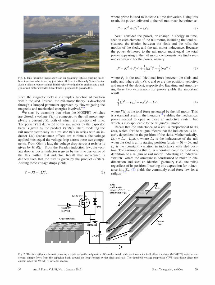
Our interest at the Kennedy Space Center is not in the useof these devices as projectile launchers, but in the possibilitythat they can be used to construct a launch assist track.NASA studies have argued that future generation launch sys-tems, composed of an air breathing hypersonic vehiclelaunched off of a high speed rail, as depicted in Fig. 1, couldsubstantially reduce the cost of placing payloads into earthorbit.6–9 Significant advantages in airframe weight, enginetype, and engine scale could be realized if this vehicle werelaunched from a ground based track at supersonic speeds(above Mach 1.2). Yet to date, most studies and prototypelaunch assist systems have proposed using linear synchro-nous motors7 or linear induction motors,9 neither of whichappear to have been demonstrated at speeds above Mach 1and which would be expensive to construct and operate.Given its relative simplicity and exceptional speed, thisraises the question, “can railgun technology be used tolaunch a hypersonic air breathing vehicle?”
Operating a railgun at relatively low acceleration (2 to 3g’s) does not change the fundamental physics—current stillflows through a closed circuit with a movable slidingarmature—however, the time scale differs by orders of mag-nitude. So the name “railgun” is a misnomer in our applica-tion and we will instead use the name rail motor below.Also, the components needed to construct a rail motor aredifferent from those used in a railgun, yet, fortuitously, thenecessary items for the development of such a device haverecently become available. In fact, a tabletop demonstration
of a low-voltage, long time-constant rail motor has been builtand operated and is described in this paper. Such a deviceboth demonstrates that rail motor launch assist may be possi-ble and provides an interesting new motor that could beconstructed as an upper-level class project.
This paper begins by developing rail motor theory and isfollowed by a description of the tabletop motor we have con-structed. Special attention is given to the power supplydesign, as this is the new enabling entity that allows the railmotor to operate. Experimental results are then presented,followed by a section on safety issues.
II. RAILGUN THEORY
It is surprisingly difficult to find a clearly stated set ofequations describing a railgun or rail motor in the literature.Many of the publications present an incomplete model withreference to prior railgun papers. Following the resultingcitation trail back in time usually yields a text on inductiveforces, the most common of which is a 1932 translation of anobscure German book on switchgear design.10 Other publica-tions develop numerical models, bypassing the need for alumped parameter model, but like the switchgear reference,provide limited physical insight. Yet, developing railgunequations is not difficult, especially for the low voltage casewhere high frequency phenomena such as skin effects can beignored. In this section such a model is developed by follow-ing, and refining, a problem proposed by Lorrain andCorson.11
Figure 2 shows a schematic of a rail motor, where the rail/sled assembly is stacked three levels high. We choose thislooped approach in order to increase the magnetic inductionand thus increase the force on the sled, understanding thatsuch an approach adds complexity and increases the backemf, thereby reducing the maximum achievable velocity. Itis assumed that the sleds are attached to each other and moveas a single entity. Such designs are reviewed in theliterature.12
Fundamentally, the force on the sleds is the result of theinteraction of the current traveling through the sleds with themagnetic field generated by the current traveling around therails. However, calculating this force directly is difficult
38 Am. J. Phys. 81 (1), January 2013 http://aapt.org/ajp VC 2013 American Association of Physics Teachers 38
since the magnetic field is a complex function of positionwithin the sled. Instead, the rail-motor theory is developedthrough a lumped parameter approach by “investigating themagnetic and mechanical energies involved.”11
We start by assuming that when the MOSFET switchesare closed, a voltage VðtÞ is connected to the rail motor sup-plying a current IðtÞ, both of which are functions of time.The power PðtÞ delivered to the rail motor by the capacitorbank is given by the product VðtÞIðtÞ. Then, modeling therail motor electrically as a resistor RðtÞ in series with an in-ductor LðtÞ (capacitance effects are minimal), the voltageapplied must equal the voltage drop across these two compo-nents. From Ohm’s law, the voltage drop across a resistor isgiven by IðtÞRðtÞ. From the Faraday induction law, the volt-age drop across an inductor is given by the time derivative ofthe flux within that inductor. Recall that inductance isdefined such that the flux is given by the product LðtÞIðtÞ.Adding these voltage drops yields
V ¼ RI þ ðLIÞ0; (1)
where prime is used to indicate a time derivative. Using thisresult, the power delivered to the rail motor can be written as
P ¼ RI2 þ L0I2 þ LI0I: (2)
Next, consider the power, or change in energy in time,seen in each element of the rail motor, including the total re-sistance, the friction between the sleds and the rails, themotion of the sleds, and the rail-motor inductance. Becausethe power delivered to the rail motor must equal the totalpower appearing in the rail motor components, we find a sec-ond expression for the power, namely
P ¼ RI2 þ Ff x0 þ 1
2ðLI2Þ0 þ 1
2ðmx0
2Þ0; (3)
where Ff is the total frictional force between the sleds andrails, and where xðtÞ, x0ðtÞ, and m are the position, velocity,and mass of the sled(s), respectively. Equating and simplify-ing these two expressions for power yields the importantresult
1
2L0I2 ¼ Ff x
0 þ mx00x0 ¼ Fx0; (4)
where FðtÞ is the total force generated by the rail motor. Thisis a standard result in the literature10 yielding the mechanicalpower needed to open or close an inductive switch, butwhich is also applicable to the railgun/rail motor.
Recall that the inductance of a coil is proportional to itsarea, which, for the railgun, means that the inductance is lin-early dependent on the position of the sleds. Mathematically,LðtÞ ¼ L0 þ LgxðtÞ, where L0 is the inductance of the railwhen the sled is at its starting position (at xðt ¼ 0Þ ¼ 0), andLg is the (constant) variation in inductance with sled posi-tion. The assumption that Lg is a constant could be used as adefinition of a railgun or rail motor, indicating an inductive“switch” where the armature is constrained to move in onedimension and sees an identical geometry (i.e., the rails)regardless of its position. Inserting this expression for induct-ance into Eq. (4) yields the commonly cited force law for arailgun1,12
Fig. 2. This is a railgun schematic showing a triple sled/rail configuration. When the metal oxide semiconductor field effect transistor (MOSFET) switches are
closed, charge flows from the capacitor bank, around the loop formed by the sleds and rails. The threshold voltage suppressor (TVS) and diode direct the
current when the MOSFET switches reopen.
Fig. 1. This futuristic image shows an air-breathing vehicle carrying an or-
bital insertion vehicle having just taken off from the Kennedy Space Center.
Such a vehicle requires a high initial velocity to ignite its engines and a rail-
gun or rail motor extended linear track is proposed to provide this.
39 Am. J. Phys., Vol. 81, No. 1, January 2013 Starr, Youngquist, and Cox 39

F ¼ 1
2LgI2 ¼ Ff þ mx00: (5)
This result is elegant in its simplicity, yet captures theessential physics. The force on the sled varies with the cur-rent and with the magnetic induction (the Lorentz force law),and the magnetic induction also varies with the current(Biot-Savart law), hence the force is proportional to the cur-rent squared. The inductance gradient then conveniently cap-tures all other dependencies as a measurable lumpedparameter.
Equation (5) connects the current IðtÞ to the sled positionxðtÞ, but a second differential equation is needed to completethe model and this is obtained by inserting the rail motor in-ductance expression into Eq. (1), yielding
V ¼ ðRþ Lgx0ÞI þ ðL0 þ LgxÞI0: (6)
The resistance has been written as a function of time toaccount for increasing resistance in the rails as the sled’sposition increases, so RðtÞ can be calculated. Also, the volt-age function can be measured or, assuming a capacitive volt-age source, appropriately modeled. The result is that Eqs. (5)and (6) form a nonlinear, coupled pair of differential equa-tions with unknown functions of position and current thatmodel the railgun or rail motor. Additional forces that mightarise with a larger-scale motor, such as air resistance and lift,are beyond the scope of this paper.
III. THE LOW VOLTAGE RAIL MOTOR
The time scale for a typical railgun is milliseconds, dic-tated by the time that the projectile is inside the gun and lim-ited by the time scale of the pulsed power supply. The powersupply should accelerate the projectile through the entirelength of the gun, but it can be expensive to construct a ca-pacitor bank of sufficient size; one researcher13 sequentiallyfired smaller capacitor banks to extend the power supplytime scale. This problem is compounded with the linearmotor where the time scale is a thousand times longer.Instead of 0.1 to 1.0 F capacitors in a typical railgun, weneed a capacitor bank with more than 1000 F. This mightseem impossible, but the high voltages used in a railgun arenot needed in the rail motor so there is a path forward.
Within the last few years, ultra-capacitors have appearedin the marketplace14 with enormous capacitances, but limitedto low voltage. For the rail motor, we chose to construct thepower supply with these new components, using 24 of theMaxwell Technology 3000 F capacitors, part numberBCAP3000P. These capacitors can be charged to 2.7 V each,have a maximum series resistance of 0.29 mX, and can bestacked using an active balancing module available fromMaxwell Technology. We configured these 24 capacitors intwo arrangements, either as three banks of 8 to provide amaximum voltage of 21.6 V, a total capacitance of about1125 F, and a minimum equivalent resistance of about0.8 mX, or as four banks of 6 (see Fig. 3) to provide a maxi-mum voltage of 16.2 V, a total capacitance of 2000 F, and aminimum equivalent resistance of about 0.44 mX. The sec-ond choice was usually preferable, with the drop in resist-ance making up for the loss of voltage, though some of ourbetter performing rail runs were made with the first arrange-ment. The actual capacitance achieved in these banks wasvoltage and time dependent, being measured by monitoring
the capacitor bank voltage versus time during charging witha known current. The 4� 6 bank showed 1600 F of capaci-tance at 2.6 V, rising to 2000 F at 10.5 V and to 2400 F at15 V, but then dropping back to 2000 F at 14 V after a fewdays. Also, the equivalent resistances of these capacitorbanks are typically higher than listed above due to the addedresistance of the interconnections. The total equivalent seriesresistance of the 4� 6 bank configuration including allconnections and electrical components was less than 2 mX.
In addition to ultra-capacitors, the other new componentthat makes the low-voltage rail motor feasible is the avail-ability of very low impedance MOSFET switches. Devicessuch as the IXTN600N04T2 power MOSFET from IXYShave been available only since the summer of 2010 and arecapable of switching up to 600 amps at 40 V with an internalimpedance of only 1.05 mX (these parameters are dependenton internal heating). We used 10 of these in parallel toincrease the current capability and decrease the resistanceten-fold. Figure 3 shows the MOSFET module in the upperleft with the copper bus-bars. The MOSFET bank was drivenusing a standard function generator to produce precisepulses, which were buffered using a MOSFET driver circuitbased on IXYS part number IXDD604PI. This circuit islocated on the small board shown in the upper left corner ofFig. 3.
Switched power supplies used to drive inductive loads,such as the rail motor, require flyback diodes, shown in Fig.2 and in the lower left of Fig. 3. The purpose of these diodesis to redirect the current flowing through the rail motor backto the rail when the MOSFET switches open. Without thesediodes, the current would flow to the open MOSFETs, caus-ing their drain voltage to rise beyond the MOSFET break-down voltage, resulting in damage. However, this is not theonly inductively coupled current in the power supply. Thereis inductance in the capacitor bank such that they continue tosupply current even after the MOSFETs have opened and theflyback diodes cannot redirect this current. In order to protectthe MOSFETs from this source of over-voltages, a 15-kW,24 -V transient voltage suppressor was placed across eachMOSFET, Littelfuse part number 15KPA24CA. These devi-ces do not conduct below 24 V, but when the MOSFETs
Fig. 3. The rail motor power supply shown above consists of a 2000-F,
16.2 -V capacitor bank, a flyback diode bank (lower left), and a MOSFET
switch bank with protective transient voltage suppressors and MOSFET
driver circuit. This power supply can be operated in pulsed or continuous
mode. It has a total equivalent series resistance of less than 2 mX and can
supply over 4000 A.
40 Am. J. Phys., Vol. 81, No. 1, January 2013 Starr, Youngquist, and Cox 40
open and the voltage starts to rise they switch rapidly (pico-seconds) into a conducting state, redirecting the currentaround the MOSFETs. Without these protections, theMOSFET bank can fail destructively as is described in thesafety section below.
The power supply described above was used to drive thetabletop rail motor shown in Fig. 4. This motor consists ofthree layers of extruded aluminum bar (1/2 in. by 3/4 in. byabout 1.1 m) bolted to each other and to a plastic sheet every4 in. with plastic sleeves around the bolts and plastic shimsbetween the bars. Three sleds are placed into the 3 in. gapbetween the rails and heavy gage electrical wire is used toclose the “coil” formed by the rails and the sleds as shown inFig. 4. Also, not shown in Fig. 4, a 3-in. diameter, 1/4-in.thick rare-earth magnet was installed in the plastic below thestarting location of the sleds. This was done to provide akick-start to the sleds and minimize welding of the sleds tothe rails.
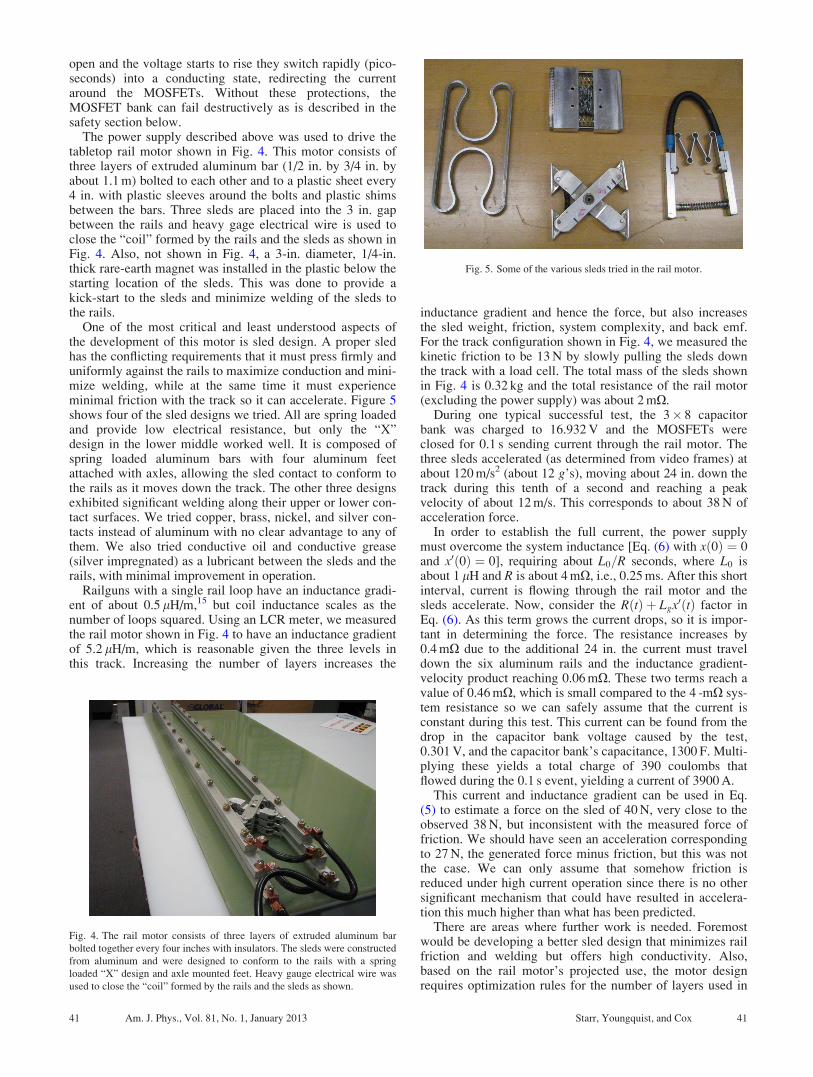
One of the most critical and least understood aspects ofthe development of this motor is sled design. A proper sledhas the conflicting requirements that it must press firmly anduniformly against the rails to maximize conduction and mini-mize welding, while at the same time it must experienceminimal friction with the track so it can accelerate. Figure 5shows four of the sled designs we tried. All are spring loadedand provide low electrical resistance, but only the “X”design in the lower middle worked well. It is composed ofspring loaded aluminum bars with four aluminum feetattached with axles, allowing the sled contact to conform tothe rails as it moves down the track. The other three designsexhibited significant welding along their upper or lower con-tact surfaces. We tried copper, brass, nickel, and silver con-tacts instead of aluminum with no clear advantage to any ofthem. We also tried conductive oil and conductive grease(silver impregnated) as a lubricant between the sleds and therails, with minimal improvement in operation.
Railguns with a single rail loop have an inductance gradi-ent of about 0.5 lH/m,15 but coil inductance scales as thenumber of loops squared. Using an LCR meter, we measuredthe rail motor shown in Fig. 4 to have an inductance gradientof 5.2 lH/m, which is reasonable given the three levels inthis track. Increasing the number of layers increases the
inductance gradient and hence the force, but also increasesthe sled weight, friction, system complexity, and back emf.For the track configuration shown in Fig. 4, we measured thekinetic friction to be 13 N by slowly pulling the sleds downthe track with a load cell. The total mass of the sleds shownin Fig. 4 is 0.32 kg and the total resistance of the rail motor(excluding the power supply) was about 2 mX.
During one typical successful test, the 3� 8 capacitorbank was charged to 16.932 V and the MOSFETs wereclosed for 0.1 s sending current through the rail motor. Thethree sleds accelerated (as determined from video frames) atabout 120 m/s2 (about 12 g’s), moving about 24 in. down thetrack during this tenth of a second and reaching a peakvelocity of about 12 m/s. This corresponds to about 38 N ofacceleration force.
In order to establish the full current, the power supplymust overcome the system inductance [Eq. (6) with xð0Þ ¼ 0and x0ð0Þ ¼ 0], requiring about L0=R seconds, where L0 isabout 1 lH and R is about 4 mX, i.e., 0.25 ms. After this shortinterval, current is flowing through the rail motor and thesleds accelerate. Now, consider the RðtÞ þ Lgx0ðtÞ factor inEq. (6). As this term grows the current drops, so it is impor-tant in determining the force. The resistance increases by0.4 mX due to the additional 24 in. the current must traveldown the six aluminum rails and the inductance gradient-velocity product reaching 0.06 mX. These two terms reach avalue of 0.46 mX, which is small compared to the 4 -mX sys-tem resistance so we can safely assume that the current isconstant during this test. This current can be found from thedrop in the capacitor bank voltage caused by the test,0.301 V, and the capacitor bank’s capacitance, 1300 F. Multi-plying these yields a total charge of 390 coulombs thatflowed during the 0.1 s event, yielding a current of 3900 A.
This current and inductance gradient can be used in Eq.(5) to estimate a force on the sled of 40 N, very close to theobserved 38 N, but inconsistent with the measured force offriction. We should have seen an acceleration correspondingto 27 N, the generated force minus friction, but this was notthe case. We can only assume that somehow friction isreduced under high current operation since there is no othersignificant mechanism that could have resulted in accelera-tion this much higher than what has been predicted.
There are areas where further work is needed. Foremostwould be developing a better sled design that minimizes railfriction and welding but offers high conductivity. Also,based on the rail motor’s projected use, the motor designrequires optimization rules for the number of layers used in
Fig. 4. The rail motor consists of three layers of extruded aluminum bar
bolted together every four inches with insulators. The sleds were constructed
from aluminum and were designed to conform to the rails with a spring
loaded “X” design and axle mounted feet. Heavy gauge electrical wire was
used to close the “coil” formed by the rails and the sleds as shown.
Fig. 5. Some of the various sleds tried in the rail motor.
41 Am. J. Phys., Vol. 81, No. 1, January 2013 Starr, Youngquist, and Cox 41

the motor, the capacitor bank configuration, the length of thetrack, etc. The acceleration profile requires smoothing; sim-ply closing the MOSFETs causes an acceleration spike fol-lowed by a decreasing acceleration, which will require amore controllable power supply. In order to scale this tech-nology to very long tracks, we believe that to minimize railresistance, a launch assist system must be segmented. Inother words, the complete system would be composed ofmany smaller linear motors with individual capacitor banks,through which the sled/vehicle would move at differentvelocities. This presents other design challenges, especiallyin the interfacing between the segments. Nevertheless, thisvision for a launch assist system is simpler, less expensive,and more feasible than those based on other linear motorapproaches. One might even suggest using solar cells tocharge the low voltage capacitor banks, making this a“green” launch system.
IV. SAFETY ISSUES
There are several safety concerns that should be consid-ered before constructing or operating one of these railmotors. First, as mentioned above, the MOSFET bank mustbe protected from inductive voltage surges, but it also mustbe protected from allowing the gate voltage to stray awayfrom ground (closed) or rail (open). If the gate voltage driftsinto a range where the MOSFETs are partially switched theycan be damaged. Figure 6 shows the results when the MOS-FETs fail and allow the energy stored in the capacitor bankto discharge through them. Note that this is not an explosiveevent—the capacitor bank takes several seconds to dis-charge—but an intense thermal breakdown of the semicon-ductors. Care must be taken in the power supply constructionand operation to follow proper grounding and voltage protec-tion practices.
The capacitor bank should be treated with a respect similarto that given to working on a car battery. Fully charged, the24 capacitors can store 130 kJ (36 W-h) of energy, which isabout ten times less than a car battery, but the availablepower can be 5–10 times higher—the total energy stored canbe delivered in about 10 s. Just as a screwdriver can bewelded to car battery terminals, it can be welded to the ca-pacitor bank terminals. Rings, keys, and metallic toolsshould be kept away from energized metal, which includesthe rails and sled.
We rarely operated the power supply at high current formore than 0.1 s due to the short length of our track. There arethermal limitations in the electronics, and care and analysis
should be taken before operating this power supply at highcurrent for longer time periods.
Finally, many of our test firings went smoothly with nodamage, but many did not. Figure 7 shows one of the moredamaging test runs imaged with a high-speed camera as thesleds traveled down the track. It is not clear to us why someruns were uneventful and then another was so damaging,leading to pitting and deposition of aluminum on both therails and the sleds. We highly recommend that eye protectionbe worn during operation of the rail motor.
V. CONCLUSIONS
Recent advances in ultra-capacitors and very low imped-ance, high-current MOSFETs have made it possible to con-struct and demonstrate a low-voltage rail motor based on therailgun concept. NASA is interested in the possibility ofusing a scaled-up version of this linear motor to launch air-breathing vehicles at speeds above Mach 1 as a first stage ofa potential space launch system. Significant work is neededto develop a launch assist system with force control and seg-mented design to provide near constant acceleration over adistance of a mile or more. The small-scale motor describedin this paper is a start in this direction. This motor could be achallenging upper-level student project demonstrating elec-tromagnetic principles and would also provide a test bed forbetter sled design and controlled current operation. Inaddition, the power supply described in this paper is capableof generating low-voltage, high-current pulses that can beused to demonstrate other inductive and electromagneticphenomena.
ACKNOWLEDGMENTS
We would like to thank Curtis Ihlefeld, Stephen Simmons,and Ariel Pavlick for helpful discussions on the power sup-ply design as well as Nicole Dufour and Mark Nurge fortechnical assistance. We would also like to acknowledge theexcellent comments made by the reviewers. This work was
Fig. 6. The MOSFET bank can fail destructively if proper precautions are
not taken, causing all of the energy stored in the capacitor bank to drain
through them.
Fig. 7. On several occasions the sled accelerated down the rails accompanied
by a shower of sparks, resulting in damage to both the sled and the rails.
42 Am. J. Phys., Vol. 81, No. 1, January 2013 Starr, Youngquist, and Cox 42

supported in part by the NASA Innovative PartnershipsProgram.
1S. C. Rashleigh and R. A. Marshall, “Electromagnetic acceleration of
macroparticles to high velocities,” J. Appl. Phys. 49(4), 2540–2542
(1978).2G. Fein, “Navy sets new world record with Electromagnetic Railgun demon-
stration,” Office of Naval Research story number NNS101210–19, December
10, 2010 <http://www.navy.mil/search/display.asp?story_id=57690>.3Ian R. McNab, “Progress on Hypervelocity Railgun Research for Launch
to Space,” IEEE Trans. Magn. 45, 381–388 (2009).4H. D. Fair, “Advances in Electromagnetic Launch Science and Technol-
ogy and Its Applications,” in 2008 14th Symposium on ElectromagneticLaunch Technology, (Victoria, British Columbia, 2008), pp. 1–6.
5R. Jones, “The rail gun: A popular demonstration of the Lorentz force,”
Am. J. Phys. 68(8), 773–774 (2000).6W. A. Jacobs, “Magnetic launch Assist—NASA’s Vision for the Future,”
IEEE Trans. Magn. 37, 55–57 (2001).7J. Dill and D. Meeker, “Maglifter Tradeoff Study and Subscale System
Demonstrations,” Foster-Miller report for NASA contract NAS8-98033,
NAS-98069-1362 (2000).
8J. C. Mankins, W. J. D.Escher, J. Howell, and J. R. Olds, “Combined air-
beathing/rocket powered highly reusable space transport flight profiles: A
progress report,” in AIAA 7th International Spaceplanes and HypersonicSystems and Technology Conference, Norfolk, Virgina, 1996, pp. 26–37.
9K. J. Kloesel, J. B. Pickrel, E. L. Sayles, M. Wright, D. Marriott, L. Hol-
land, and S. Kuznetsov, “First Stage of a Highly Reliable Reusable Launch
System,” in AIAA Space 2009 Conference and Exposition, Pasadena,
California, 2009, pp. 1–14.10I. F. Kesselring, The Elements of Switchgear Design (Sir Isaac Pitman and
Sons, London, 1932).11P. Lorrain and D. Corson, Electromagnetic Fields and Waves, 2nd ed.
(W.H. Freeman, San Francisco, 1970), Section 8.9 and problem 8–28.12T. G. Engel, M. J. Veracka, J. M. Neri, and C. N. Boyer, “Design of low-
current high-efficiency augmented railguns,” IEEE Trans. Plasma Sci.
37(12), 2385–2389 (2009).13M. Del Guercio, “A 4.5-MJ pulsed power supply for railgun experiments,”
IEEE Trans. Magn, 39(1), 280–284 (2003).14Pawan Sharma and T. S. Bhatti, “A review on electrochemical double-
layer capacitors,” Energy Convers. Manage. 51, 2901–2912 (2010).15T. G. Engel, M. J. Veracka, and J. M. Neri, “The specific-force perform-
ance parameter for electromagnetic launchers,” IEEE Trans. Plasma Sci.
38(2), 194–198 (2010).
43 Am. J. Phys., Vol. 81, No. 1, January 2013 Starr, Youngquist, and Cox 43