A Low Cost System for Autonomous Surface Vehicle based...
17
Proceedings: U.S. Hydrographic Conference, National Harbor, MD, 16-19 Mar 2015 1 A Low Cost System for Autonomous Surface Vehicle based Hydrographic Survey Damian Manda 1 , May-Win Thein 2 , Andrew D’Amore 3 , Andrew Armstrong 4 1,4 NOAA Office of Coast Survey, NOAA-UNH Joint Hydrographic Center 1,2,3 Ocean Engineering Department, University of New Hampshire 24 Colovos Road, Durham NH 03824, United States 1 [email protected] (970) 231-9672 2 [email protected], 3 [email protected], 4 [email protected] Author Biography Damian Manda is an officer in the NOAA Corps, currently stationed at the University of New Hampshire where he is pursuing a master’s degree in Ocean Engineering. His research focuses on development and field implementation of autonomous surface vehicle behaviors for hydrographic survey. Abstract Use of autonomous vehicles for hydrographic surveying has been primarily limited to underwater systems with autonomous surface vehicles only recently entering routine use. Operation on the ocean surface simplifies position measurement, relaxes power limitations and reduces hull sealing, which reduces design costs for vehicles. However, the existing systems for autonomous command and control are often proprietary, expensive and designed for a single platform. The system developed at the Joint Hydrographic Center minimizes cost while maximizing functionality and flexibility by leveraging mass produced, open source hardware and software. Long range Wi-Fi is utilized for monitoring the autonomous operation vessel and provides the ability to natively interface onboard sonar systems with acquisition software. A hobby radio control system is used for remote human override. Onboard processing uses an embedded Linux platform running the open source MOOS-IvP autonomy framework. Sensor input and control output as well as fail-safes are handled by an independent microcontroller. Position and orientation input can be accepted from an existing source on the vessel or use a MEMS INS for simple deployments. The total autonomy system cost is under $1000. The system is being initially integrated and tested on the NOAA 1.7 m micro ASV EMILY for shallow water hydrography.
Transcript of A Low Cost System for Autonomous Surface Vehicle based...
Proceedings: U.S. Hydrographic Conference, National Harbor, MD, 16-19 Mar 2015
1
A Low Cost System for Autonomous Surface
Vehicle based Hydrographic Survey
Damian Manda1, May-Win Thein2, Andrew D’Amore3, Andrew Armstrong4
1,4NOAA Office of Coast Survey, NOAA-UNH Joint Hydrographic Center 1,2,3Ocean Engineering Department, University of New Hampshire
24 Colovos Road, Durham NH 03824, United States [email protected] (970) 231-9672
[email protected], [email protected], [email protected]
Author Biography
Damian Manda is an officer in the NOAA Corps, currently stationed at the
University of New Hampshire where he is pursuing a master’s degree in Ocean
Engineering. His research focuses on development and field implementation of
autonomous surface vehicle behaviors for hydrographic survey.
Abstract
Use of autonomous vehicles for hydrographic surveying has been primarily limited to
underwater systems with autonomous surface vehicles only recently entering routine use.
Operation on the ocean surface simplifies position measurement, relaxes power limitations and
reduces hull sealing, which reduces design costs for vehicles. However, the existing systems for
autonomous command and control are often proprietary, expensive and designed for a single
platform.
The system developed at the Joint Hydrographic Center minimizes cost while maximizing
functionality and flexibility by leveraging mass produced, open source hardware and software.
Long range Wi-Fi is utilized for monitoring the autonomous operation vessel and provides the
ability to natively interface onboard sonar systems with acquisition software. A hobby radio
control system is used for remote human override. Onboard processing uses an embedded Linux
platform running the open source MOOS-IvP autonomy framework. Sensor input and control
output as well as fail-safes are handled by an independent microcontroller. Position and
orientation input can be accepted from an existing source on the vessel or use a MEMS INS for
simple deployments. The total autonomy system cost is under $1000.
The system is being initially integrated and tested on the NOAA 1.7 m micro ASV EMILY for
shallow water hydrography.

Proceedings: U.S. Hydrographic Conference, National Harbor, MD, 16-19 Mar 2015
2
Introduction
Marine vehicles were the first place to widely introduce automated navigation systems, though
the use of autopilots for heading control during long transits, and had some of the first
demonstrated long distance voyages in the 1920s. However, modern large ship autopilots today
remain very similar in capability these early models, being able to follow tracks and headings but
not assimilate other information and react to a changing environment. Recent work in
autonomous land vehicles and aircraft allow them to operate for long periods of time in complex
situations without human guidance, but marine vehicles have not received as much attention.
For hydrographic surveying, autonomous underwater vehicles (AUVs) were introduced in the
1990s and became more feasible for routine surveys in the following decade. AUVs take
advantage of submergence to survey closer to the seafloor and are much less affected by surface
conditions than traditional marine vessels, but still have major limitations. They are limited in
operational time by battery capacity, and in many designs require batteries to be recharged
internally before returning to operation. In typical operation, absolute positioning can only be
achieved at the surface, forcing use of high accuracy inertial measurement units and Doppler
velocity logs to meet hydrographic data uncertainty standards, which drive up costs. Pressure
sealing and redundant systems required for reliable operation underwater necessitate stringent
engineering therefore high development and production costs.
Many of these costs and concerns can be greatly reduced through the use of small autonomous
surface vessels (ASVs). Continual satellite positioning allows for compensation of errors in less
accurate inertial navigation units, and the ability to receive radio frequency signals also permits
transmission of RTK corrections for increased accuracy when a system is available. Hull sealing
only needs to withstand wave action, and absolute reliability in operation is not paramount since
the vessel will continue floating and can be more easily recovered if it malfunctions or runs out
of power. Air breathing engines or generators facilitate improved operating time and batteries
can be much more easily swapped than with a pressure sealed hull. ASVs inherit the difficulties
of surveying in rough weather from manned vessels, and may have to contend with traffic from
other vessels. Therefore, they are an attractive solution for relatively isolated and shallow water
environments, especially for development and use on a limited budget. The system covered in
this paper will initially be implemented on small ASVs for low traffic, near shore applications,
but is designed to be flexible for application to a variety of platforms.
There are relatively few existing commercial solutions that match the system described above,
and a full system including an ASV and autonomous control system with varying behavior
capabilities typically costs more than $50,000. The sonar and survey positioning system then
have to be provided on top of the platform cost. The computers providing the autonomous
control cost multiple thousands of dollars for this component alone, and often are only able to
follow a simple series of predefined waypoints. This paper describes a system developed at the
University of New Hampshire and NOAA/UNH Joint Hydrographic Center to command the
behavior of an ASV for low hardware cost, while incorporating additional functionality to allow
carrying out hydrographic survey operations with minimal human pre-planning and operational
intervention. It leverages widely used hardware and open source software to create an ecosystem
that is accessible to other developers and allows it to be rapidly adapted for different platforms
and operational regimes.

Proceedings: U.S. Hydrographic Conference, National Harbor, MD, 16-19 Mar 2015
3
Hardware Components
Data Processing and Control System
The hardware underlying the autonomous control system consists of multiple commercially
available components that interact to make navigation decisions and drive the control surfaces of
the ASV. Identical sets of hardware are currently being used by 3 parallel development efforts at
the University of New Hampshire for implementation on different ASVs, which is made possible
by the low-cost availability and the flexibility of the hardware system for interfacing with a
variety of devices.
The core intelligence of the system is supported by a BeagleBone Black (BBB) embedded Linux
computer. The BBB was selected for this project due to its low cost ($55), relatively large
development community and increased performance over other small embedded systems
available at the initiation of development such as the Raspberry PI Model B+, Gumstix and Intel
Galileo. It also has additional user accessible input and output capabilities not present on these
other devices. The BBB uses a 32-bit single core ARM Cortex-A8 (ARMv7-A) architecture
processor running at 1 GHz. The board has 512 MB of DDR3-800 RAM and 4 GB of onboard
eMMC storage with additional storage capability on a microSD card [1]. A key feature for the
flexibility of the autonomy system is provided by the additional serial ports wired to the
accessible headers, with 3 ports available for devices and sensors to communicate with the BBB.
These ports operate at a 3.3 V level, so to interface with a RS232 or 5 V source, a voltage level
converter is necessary, but this is a simple and cheap addition. The USB Host capability of the
BBB allows USB devices to be interfaced or further serial devices through USB to serial
adapters if possible increased latency is not a concern. The BBB can also communicate
externally via the SPI, I2C and CAN protocols allowing flexibility in sensor choices including
traditionally automotive oriented sensors.
Multiple versions of Linux designed for ARM computers are available for the BBB. For this
project, Ubuntu 14.04 was chosen, which uses the 3.14 Linux kernel for the current BBB
version. Using a mainstream Linux distribution simplifies compatibility with applications and
drivers and increases the ease of transitioning the developed autonomy system to other platforms
that support Ubuntu or Debian Linux based operating systems.
A separate microcontroller was chosen to interact with the physical systems on the boat and
accept human remote control input. Since a dedicated microcontroller is more suitable for
timing sensitive task such as PWM output and pulse length detection, this choice enables robust
operation without worry about interference from processor intensive autonomy determinations.
The Arduino Mega 2560 was selected as the microprocessor platform due to existing usage
within the university, the large community of Arduino developers, an operating voltage of 5 V
and capability to natively handle more serial data streams and interrupts than other Arduino
platforms. The Mega 2560 uses an Atmel ATmega2560 processor running at 16 MHz, and has 4
serial UARTs, up to 15 PWM outputs and 6 hardware interrupts. It also supports communication
with other devices via SPI and I2C as well as many analog and digital inputs [2]. The BBB
communicates autonomy commands with the Arduino over a serial link, and can accept input
from sensors interfaced to the Arduino as well allowing for additional serial devices if a specific

Proceedings: U.S. Hydrographic Conference, National Harbor, MD, 16-19 Mar 2015
4
implementation exceeds the input capacity of the BBB. The PWM outputs allow driving of
stepper and servo motors and interrupts are used for input from a hobby RC receiver. In the
ASV implementation for this project, two waterproof hobby servos are used to control the
throttle of a gas engine and output nozzle angle of a jet drive system (the “rudder”).
A standard hobby radio control transmitter and receiver allow human override of the control for
the ASV system, useful for launch and recovery as well as recovery from undesired behaviors.
The Futaba 6J 6-channel system with R2006GS receiver was chosen for low cost while having
enough channels to control required functionality. However, the system is designed such that
any radio system providing standard servo (PWM) outputs can be used, as the Arduino interprets
the inputs directly from the receiver outputs for each channel. For the developed system, the RC
controller provides throttle, rudder and motor starting commands as well as a switch to select
human or autonomous control. The range of most hobby RC controllers are sufficient to control
the ASV within a distance where observation by eye is reasonable, and thus do not require
additional amplifiers or high gain antennas, lending to the simplicity and compact design of this
hardware system.
Communication and Positioning
For communication between the autonomy system and a shore or ship based monitoring station,
long distance Wi-Fi is used. The standard protocol allows for consumer equipment to be used,
and although output power is typically limited to 1 W, this has been shown to give a sufficient
range for communication within line of sight. The ASV has a 3 dBi omnidirectional antenna for
a wider beam width to allow robust connections with possible vehicle dynamics, while the more
stationary shore station antenna has an 8 dBi omnidirectional antenna. This means that the signal
from vehicle to shore will likely be lost first, allowing the vehicle to still be commanded back
into range when the return signal starts to be dropped. If additional range performance is desired
where the wave conditions are anticipated to be calm, a higher gain antenna could be used on the
ASV.
The implemented system uses an Alfa Tube-U(N) 802.11n capable USB Wi-Fi adapter for both
the ASV and the shore computer, which provides 1 W power output. The USB connection
allows direct connection to the BBB, which can then communicate with the shore station. The
shore station can be any available Mac or Linux computer using another Tube-U(N) or other
high powered Wi-Fi adapter acting as an access point. In the case of the Tube-U(N), no
additional hardware is required as the adapter is powered by the laptop. If more devices are
desired to connect via Ethernet on the shore side, a Ubiquity Bullet BM2HP can be substituted
for approximately the same cost. The autonomy system can also connect to infrastructure Wi-Fi
networks for testing in the office or research environment. The BBB bridges traffic from its
Ethernet port to the Wi-Fi connection, allowing other network devices such as a sonar system on
the ASV to be monitored and controlled from the shore station when in range.
Since this hardware system is intended to be able to retrofit any vessel for autonomy, it may be
interfaced with an existing inertial positioning system that can output NMEA positioning and
velocity data for use in the autonomous navigation. However, for the purpose of developing a
complete package that is usable for single beam sonar survey applications and for installation on
the development ASV, a dedicated inertial navigation system (INS) is integrated. The

Proceedings: U.S. Hydrographic Conference, National Harbor, MD, 16-19 Mar 2015
5
CHRobotics GP9 GPS-Aided INS was selected for this purpose due to acceptable accuracy and
ease of integration despite very low costs compared to similar systems. The GP9 is a MEMS
based inertial unit, with temperature calibration, barometric compensation of heights and an
internal Kalman filter to compensate for accelerometer and gyroscope biases using the GPS. It
interfaces natively with the GP9 using a 3.3V TTL serial connection, and the binary data format
is decoded in the autonomy software. With a GPS signal, it has specified accuracies of 1° in roll,
pitch and heading and 2.5 m positioning at a 95% confidence interval [3], [4]. These accuracies
are sufficient for IHO Order 1b uncertainty standards [5] when using single beam sonar, since
beamwidths on a small system would be larger than the roll and pitch accuracies. If a multibeam
sonar is desired to be used on an ASV with this system, better positioning and orientation would
be required, but could still be achieved with a compact, low power MEMS system like the SBG
Ekinox or possibly even the SBG Ellipse-D in shallow water [6]. However these systems start at
an order of magnitude more expensive than the GP9 and therefore would have to be selected on a
per-application basis.
The focus of this project is on hardware development and implementation of autonomy, but the
final design is intended to be able to automate hydrographic survey operations, which will
require a sonar for testing. Like the positioning input, in future applications the system will be
able to leverage existing sonar equipment as long as it can provide information on depth and
swath width for multibeam sonars, but again for this development a low power, relatively
inexpensive single beam will be integrated. The final system has not been determined, but a
possibility is the CEE Hydrosytems CEEPulse. These systems have been integrated on a similar
small unmanned boats by Teledyne OceanScience, the Z-Boat 1800 [7]. A small multibeam
system can also be integrated on an ASV of this type, and Z-Boats have been deployed with
R2Sonic 2020 systems. The autonomy behaviors developed for this system are designed to take
advantage of multibeam sonar data if available, as described later in this paper.
Power
The hardware components for autonomy have been selected to run on a single power system, as
all are capable of running on 5 V DC. The prevalence of USB based charging means 5V battery
supplies are widespread in the form of rechargeable power banks designed for recharging phones
and other mobile electronics. Fast charging of high powered devices leads many of these to
support 2 amp or higher output. For this implementation, the ruggedized New Trent PowerPak
Xtreme, with 12000 mAh capacity is used. The PowerPak has two USB outputs, one capable of
1 A output and the other 2.1 A. It can be recharged using any USB charger with a micro USB
cable, simplifying deployment by not requiring a complicated charging system.
The power distribution in the system goes directly to the BBB, any servos needed for control and
a USB hub. The USB hub allows the BBB to use more than one USB device and provides power
to them separately from the BBB. The wireless adapter and Arduino connect to the BBB
through and are powered by the USB hub. The GP9 INS is powered by a 5V output on the
header of the BBB. Since it has a low current draw, the RC receiver is powered from the 5V
output on the Arduino. The BBB is powered from the 1 A output port on the PowerPak and the
remainder of the system from the 2.1 A port. Future addition of a sonar system will require an
auxiliary power system, since the suggested systems require at least 12 V DC and it is

Proceedings: U.S. Hydrographic Conference, National Harbor, MD, 16-19 Mar 2015
6
advantageous to have a separate clean power source for the sonar system that would not be
affected by the other electronics.
A summary of the power and data connections between hardware devices in the core autonomy
system is shown in Figure 1.
Figure 1: Hardware power distribution and data communication
System Integration
The hardware for the core system will be housed in a watertight (at least IP65) container that can
be mounted on the vessel. The GP9 will be aligned with the container such that it can be rigidly
mounted and the orientation of the motion sensor referenced to the vessel. Plugs will be
provided for external mounting of the antennas for Wi-Fi and GPS as well as connection to the
control surfaces of the vehicle. However, as the target vessel for initial deployment was only
delivered to the university recently, the enclosure has not been finalized.
The total cost of the autonomy system was minimized while allowing for flexibility in
configuration for application to a variety of vessel platforms as explained above. The costs of
the components are given in Table 1. This table also includes the shore station components for a
total cost.

Proceedings: U.S. Hydrographic Conference, National Harbor, MD, 16-19 Mar 2015
7
Device Cost
ASV System
Autonomy Computer Beaglebone Black $55
Microcontroller Arduino Mega 2560 $46
GPS/INS CHRobotics GP9 $399
Hobby RC System Futaba 6J $180
Long Distance Wi-Fi + Antenna Alfa Tube-U(N) $50
USB Hub AmazonBasics 4 Port Powered $19
System Power NewTrent PowerPak Xtreme $24
Subtotal $773
Shore Monitoring System
Long Distance Wi-Fi + Antenna Alfa Tube-U(N) $55
Antenna Stand Impact 9.6' Studio Light Stand $36
Total $864
Table 1: Component Costs
Table 1 omits the cost of cabling and the enclosure, but these are expected to keep the total cost
just under $1000. If the vessel on which the system is installed already possesses a high
accuracy positioning and attitude system, the most expensive single component can be
eliminated without loss of functionality, bringing the cost of implementing autonomy on the
vessel to around $600 if no additional equipment is needed to actuate the control surfaces.
Software
The MOOS-IvP open source autonomy framework maintained by MIT and Oxford forms the
basis for the autonomy system [8]. The software compiles and runs on most Linux and Mac OS
X systems, including embedded ARM based systems such as the BBB in this system. The
MOOS (Mission Oriented Operating Suite) is a database like system that handles postings from
MOOS applications and distributes them to other applications. In an autonomous vehicle, these
postings are information about the status of subsystems, the position of the vehicle and the
environment in which it is operating. MOOS uses TCP connections to transfer information, so
the core MOOS process can be on the same computer as the applications or a different one
across a network. MOOS also includes applications that add functionality for sharing
information between MOOS databases, so that each maintains up to date copies of certain
information when networked, but allows multiple independent instances to run. This can
facilitate interaction between different vehicles in a swarm, or in this case is used for the
monitoring station to interact with the vehicle while not affecting operations if it is out of range.
The MOOS-IvP package comes with applications for common tasks in marine autonomy and can
be extended to interface with platform specific systems.
A key MOOS application is the IvP (Interval Programming) helm, which defines the actual
behaviors for autonomy and commands the heading and speed of the ASV. The MIT repository
includes existing behaviors for waypoint navigation, collision avoidance, following other
vessels, and station keeping along with simple constant heading and speed behaviors. It includes

Proceedings: U.S. Hydrographic Conference, National Harbor, MD, 16-19 Mar 2015
8
the ability to build a hierarchical behavior structure from these behaviors, and facilities are
exposed for development of custom behaviors. Behaviors may also be updated from other
MOOS applications, for example the waypoint navigation behavior could receive a new set of
waypoints from a separate path planning MOOS application.
Implementation of MOOS for this system
For the implementation of the autonomy system, hydrographic survey behaviors and deployment
on the test ASV, custom MOOS applications were developed. The interaction of these and the
core MOOS applications used in the autonomy system is presented in Figure 2. The naming
convention for MOOS apps includes a prefix denoting the type of application (p for general
process, i for interface, u for utility/simulation) which is reflected in the diagram.
Figure 2: Diagram of interaction between MOOS applications in autonomy system
Developed applications for this project include interfaces with the GPS/INS, Arduino and sonar
as well as supplemental apps for depth adaptive survey planning. The planning apps feed
information back into to the IvP waypoint behaviors, which then follow the designated paths for
surveying. For basic operation, the IvP helm also contains a default configuration for generation

Proceedings: U.S. Hydrographic Conference, National Harbor, MD, 16-19 Mar 2015
9
and following of regularly spaced “lawnmower” pattern survey lines. The shoreside MOOS
community is much simpler, with shared information on the vessel status displayed on the
pMarineViewer GUI provided with the MOOS-IvP framework. This GUI with an example
lawnmower pattern in a local lake is shown in Figure 3. Unfortunately the GUI is lightly
featured and only pre-defined simple commands to be sent to the ASV and does not allow
modification of displayed waypoints or operation regions. However, since it is open source
software, it is possible this functionality could be added during further development.
Figure 3: MOOS-IvP graphical vessel and autonomy status display
Each MOOS mission is defined through a text-based configuration file that is also used to launch
the full autonomy system and supporting processes automatically. The behaviors followed by
the IvP helm and conditions under which they are active are defined in a separate file. Different
mission files can therefore be developed for different conditions, vessels, locations and survey
equipment. Plug in files allow common configuration information for applications used in all
circumstances. Many applications have numerous options, and there is a significant learning
curve in writing the configuration files by hand, so an automatic GUI based tool for configuring
common options is under development to enable easy reconfiguration of the autonomy system
developed in this project.
The hydrographic survey specific MOOS applications and behaviors for the IvP helm enable the
system to automatically survey an assigned region with a single or multibeam echosounder while
adaptively planning lines for full coverage and avoiding newly discovered shallow areas. This
behavior requires an operation region to be defined, as well as an initial set of waypoints (which
could be an offshore border of the region). The path planner will then record information while
driving the current path to inform planning of the next one. The simplest mode of operation with
a single beam sonar is to use fixed line offsets, or offsets as a percentage of depth until a depth

Proceedings: U.S. Hydrographic Conference, National Harbor, MD, 16-19 Mar 2015
10
threshold is reached, at which time the ASV can conclude survey operations or move on to
another region.
When a multibeam sonar is available, swath information is recorded as the vessel surveys and
fed into the application which plans the next survey line at the conclusion of the current one.
The algorithm assimilates periodic swath minimums to ensure data overlap between subsequent
survey lines, while avoiding areas where turns would be very rapid due to accumulated similar
swaths and large depth changes. These areas are set aside for later revisit, and the surveying
continues until a shallow threshold is reached. When an operation region is completed, the ASV
can halt or advance to another region as in the single beam case. The full structure of IvP
autonomy behaviors is diagrammed in Figure 4.
Figure 4: IvP helm states and related behaviors for hydrographic survey
The green lines in Figure 4 indicate the normal behavior progression, where an ASV is deployed,
transits to a survey region and surveys lines, with turns between aligning heading in advance of
the next line. The waypoints for the survey lines are updated dynamically by pSurveyPath as
shown in Figure 2. The state structure allows the ASV to return home (as well as be deployed
into a loitering state) at any time. Upon completion of assigned survey areas or when faults
occur, the vessel holds station until it can be retrieved. This behavior implementation has not
been tested in the field due to recent arrival of the test platform and the planned initial confined
testing ground (a lake with UNH facilities) being frozen, but the portions using included
behaviors have been successfully simulated using tools included with MOOS-IvP. The
generation of waypoints by the path planning MOOS application has also been simulated, and
some example results are presented below in Figure 5. These simulations do not take into
account the turns between lines and only show the portion of the path that lies within the defined
operation region (black bounding polygon in the figure).

Proceedings: U.S. Hydrographic Conference, National Harbor, MD, 16-19 Mar 2015
11
Sloped Bottom, “Correct” Initial Direction
Sloped Bottom, “Wrong” Initial Direction
Linear Hump Feature
Complicated Feature, Non-Parallel Initial Segment
Figure 5: Hydrographic Survey Path Planning Examples, white line shows path of the vessel. Reds are the
shallowest depths and blues are the deepest.
In all of these simulations, the white line shows the path of the vessel, including between survey
lines, and the black box defines the operation region. The depths vary from shallow to deep in
different patterns, but the absolute depth ranges vary between individual simulations in the
figure. The region is square for all the examples in Figure 5, but can be any polygon. The
algorithm does not assume any prior knowledge of depths, and bases all subsequent swaths from
an input first swath, so inefficient patterns such as the upper right can result from poor mission
planning or unexpected topography. Future development will focus on improving the path
planning to better account for complex topography.

Proceedings: U.S. Hydrographic Conference, National Harbor, MD, 16-19 Mar 2015
12
The Arduino software is focused on providing redundancy for operation in case the MOOS
system fails to operate correctly. Based on the position of a switch on the RC controller, it will
either attempt to use commands sent from the BBB, or override this input and pass through the
human input from the controller. On the implementation for this project, the Arduino interprets
input from the RC controller to start a gas engine when first launching the ASV. When in
autonomy mode, the software monitors reception of serial data from MOOS-IvP and uses them
to control the throttle and rudder during normal autonomous operation. Even if there is no
change necessary to the control surface positions, the iMOOSArduino application continues to
output the same values over the serial link. This is used as a fail-safe, if the Arduino does not
receive new commands in a 5 second period, it will set the throttle and rudder to a preconfigured
state, such as halting the motor and centering the rudder or running at a slow speed in a circle.
System Load Testing
The full hardware and software system has been bench tested to ensure that it will operate as
expected in the field once weather conditions allow deployment on the pond. MOOS provides a
“Time Warp” setting for simulations which accelerates the processing to a specified number of
times faster than realtime. This allows for determination of possible maximum loads and the
operation of the system under these conditions.
CPU Load
The MOOS simulations were run at varying Time Warps to assess the capability of the BBB to
handle a full MOOS-IvP environment similar to what would be experience on the vessel. Using
a simulation which continually repeated a lawnmower pattern, the average CPU loads over a 20
second period were assessed using the command line sar tool while the IvP helm was idle (before
deployment) and while conducting the survey. These results are presented in Figure 6. Within
the MOOS environment, the IvP helm application was the most demanding on processor usage.
During the real-time simulation, the impact of adding shore monitoring was also assessed. This
was found to increase the load on the processor by about 5% of capacity.
Proceedings: U.S. Hydrographic Conference, National Harbor, MD, 16-19 Mar 2015
13
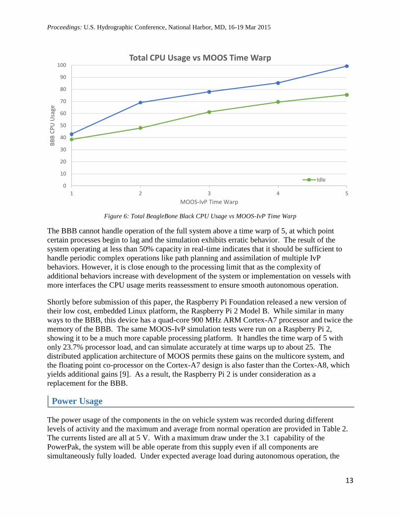
Figure 6: Total BeagleBone Black CPU Usage vs MOOS-IvP Time Warp
The BBB cannot handle operation of the full system above a time warp of 5, at which point
certain processes begin to lag and the simulation exhibits erratic behavior. The result of the
system operating at less than 50% capacity in real-time indicates that it should be sufficient to
handle periodic complex operations like path planning and assimilation of multiple IvP
behaviors. However, it is close enough to the processing limit that as the complexity of
additional behaviors increase with development of the system or implementation on vessels with
more interfaces the CPU usage merits reassessment to ensure smooth autonomous operation.
Shortly before submission of this paper, the Raspberry Pi Foundation released a new version of
their low cost, embedded Linux platform, the Raspberry Pi 2 Model B. While similar in many
ways to the BBB, this device has a quad-core 900 MHz ARM Cortex-A7 processor and twice the
memory of the BBB. The same MOOS-IvP simulation tests were run on a Raspberry Pi 2,
showing it to be a much more capable processing platform. It handles the time warp of 5 with
only 23.7% processor load, and can simulate accurately at time warps up to about 25. The
distributed application architecture of MOOS permits these gains on the multicore system, and
the floating point co-processor on the Cortex-A7 design is also faster than the Cortex-A8, which
yields additional gains [9]. As a result, the Raspberry Pi 2 is under consideration as a
replacement for the BBB.
Power Usage
The power usage of the components in the on vehicle system was recorded during different
levels of activity and the maximum and average from normal operation are provided in Table 2.
The currents listed are all at 5 V. With a maximum draw under the 3.1 capability of the
PowerPak, the system will be able operate from this supply even if all components are
simultaneously fully loaded. Under expected average load during autonomous operation, the
0
10
20
30
40
50
60
70
80
90
100
1 2 3 4 5
BB
B C
PU
Usa
ge
MOOS-IvP Time Warp
Total CPU Usage vs MOOS Time Warp
Idle

Proceedings: U.S. Hydrographic Conference, National Harbor, MD, 16-19 Mar 2015
14
12000 mAh battery pack can run the system for over 11 hours. If longer duration missions are
required, additional battery packs could be added in parallel.
Component Maximum [mA] Normal Operation [mA]
BeagleBone Black 803 542
Arduino 153 144
GP9 135 97
RC Reciever 30 21
Servo (2 Total) 600 5
Tube-U(n) 183 179
USB Hub 44 44
Total 2548 1037
Table 2: Current draw of ASV autonomy components, all operate at 5 V
The power usage of the BBB was also broken down in detail by selectively enabling subsystems
on the board. In a basic installation on an ASV, the BBB will not have a monitor connected,
USB devices will be separately powered through the hub, data is transferred through Wi-Fi and
the Ethernet port will not be needed, while MOOS-IvP runs in real-time. This forms the normal
operation scenario given in Table 2. The minimum current is observed when the BBB is fully
idle, with no monitor connection, all networking disabled and no USB devices. As additional
devices and services are added, the power usage increases as detailed in Table 3.
BeagleBone Black Subsystem Current Draw [mA]
Base Idle BBB 195
USB Hub Attached 87
Wi-Fi 178
Ethernet 88
HDMI Monitor 66
MOOS-IvP Real-time 60
MOOS-IvP Time Warp 5
(full processor load)
152
Table 3: Approximate power usage of BBB subsystems
The currents listed in Table 3 are approximate, and would likely vary with exact usage, for
example how much traffic is being passed over the network, or the exact scenario run in MOOS-
IvP, but give a general breakdown. Even through the Wi-Fi adapter is powered separately
through the hub, enabling the adapter increases power, likely because of the use of processing
power for the driver and USB interface, as well as the hub power supply potentially not fully
driving the adapter. If low power operation is required to increase mission endurance at the
expense of functionality, for example for a long term loitering operation, the communication
subsystems could be shut down to save over 1.3 W of power to the BBB, in addition to 895 mW
for the Wi-Fi adapter itself.

Proceedings: U.S. Hydrographic Conference, National Harbor, MD, 16-19 Mar 2015
15
Network Usage and Wireless Communications
Local communication among the MOOS applications running on the BBB and transmissions to
the shore station were analyzed with the nethogs and iftop command line tools. While running
the lawnmower pattern simulation, before deployment local communication was 35 KB/s, while
adding the shoreside monitoring passed 2KB/s over the Wi-Fi. When deployed, the local traffic
increased to 50 KB/s and with shoreside to 4 KB/s. The traffic increased slower than linearly for
higher timewarps, taking about 4 times the bandwidth at a timewarp of 5. This traffic is much
lower than maximum single stream 802.11n throughput of 9 MB/s at full signal strength [10],
and allows for data transmission from other equipment and reduced signal long distance
monitoring. Even the lowest speed mode of 802.11n far exceeds these data rates at about 900
KB/s.
The wireless communication system was tested between the shore station with an antenna height
of about 2.5m and a roving laptop in place of the ASV over a line of sight path on land.
Throughput and signal strength were sufficient for the data passed for status updates on the
vehicle to the limit of available line of sight distance in the testing location, 425 m. At this
distance, the reduced signal strength from the 3 dBi antenna on the roving station had lowered
throughput levels, so for longer range monitoring in benign conditions, a higher gain antenna
should be used. With a higher gain antenna, range of over a kilometer could be expected based
on the results of similar applications.
Integration on Vessel Platforms
For testing of the autonomy system and behaviors in a survey environment, the system will be
integrated onto the NOAA EMILY small ASV. EMILY is a 1.7 m, 35 kg unfueled, gas
propelled, high endurance vehicle, shown in Figure 7. The vessel was designed to collect
weather data in hurricanes and contains an existing limited autonomy system, which will be
replaced by the one described in this paper. For custom systems, EMILY has a mostly sealed
forward compartment measuring 30 cm x 26 cm x 15 cm and a compartment where the stock
electronics are housed in 34 cm x 27 cm x 20 cm space. The EMILY for use in this project was
recently delivered to UNH, so integration has been planned as described in this paper but not yet
executed.
Figure 7: The NOAA EMILY ASV

Proceedings: U.S. Hydrographic Conference, National Harbor, MD, 16-19 Mar 2015
16
While the gas engine permits extended duration missions, it does not have a transmission or
geartrain, and therefore the vessel cannot stop without shutting the motor off. Minimum speed is
around 2 kts, so the autonomy system must use a circle type pattern to hold position if the motor
is kept running during operation. There is also a possibility that the motor could shut off
unexpectedly during operation at low throttle settings, which has been observed during testing of
the platform. The motor provides a tachometer output which the Arduino will monitor and take
control to restart the motor if failure occurs mid mission. To control the electric starter motor for
both manual launches and automatic restarts the Arduino triggers an existing relay that provides
power from a dedicated lead-acid battery.
The EMILY platform also provides a variety of environmental sensors, including air and water
temperature and wind which could be interfaced for data collection where possible, but this is not
a primary goal of the project. Further development by the manufacturer on the engine system
used in EMILY has resulted in a version with a 75 W generator which could continually power
the autonomy system and additionally support a sonar and advanced inertial measurement unit
drawing up to about 60 W, opening up the possibility of long duration multibeam survey
operations using a compact system such as the R2Sonic 2024 or Teledyne Odom MB1.
The core autonomy system is also being implemented on two other small vessels at UNH. One
uses a custom hull that was constructed by an undergraduate group in 2013-2014 and is currently
undergoing reworking by a PhD student for use in experiments about coordination between
multiple boats and control system development. Another undergraduate group is retrofitting a
commercial hobby RC boat for autonomy. This retail package costs about $1000, so a complete
ASV using this hull and the autonomy system from this paper totals under $2000. Both of these
systems use electric motors, reducing operation time compared to EMILY but simplifying use in
confined spaces.
Discussion
This paper presents a hardware and software structure that form a complete system for
autonomous control of a marine vessel. Use of mass produced components and open source
software drives the total cost of the system to be under $1000, while allowing flexibility for
integration on diverse platforms. Where possible, components using widely supported standards
such as Wi-Fi and hardware with large surrounding development communities were selected to
facilitate future development and compatibility with new devices. The system can interface with
sensors and other ASV systems using a wide variety of protocols and these can be integrated into
the software environment by writing an interface application without modifying the core
autonomy system and its behaviors.
Future development will focus on real world testing of the system on the EMILY ASV and other
implementations at the University of New Hampshire. It is envisioned to eventually deploy the
ASV in both near shore high current and open ocean environments, which will likely merit
improvements to the control system to achieve suitable path following. Dynamic models of the
ASV platforms at UNH are under development to assist in control systems tuning. The multiple
platforms developed at UNH along with the ability to replicate autonomous control at low cost
also permits future research within the department to address coordination between multiple
ASVs.

Proceedings: U.S. Hydrographic Conference, National Harbor, MD, 16-19 Mar 2015
17
Installation of a sonar system on EMILY will allow the hydrographic survey specific path
planning algorithms to be tested in the field. For data collection with a multibeam sonar,
addition of a more capable computer system would allow for processing and analysis of the data
for revisit of areas that were missed before the ASV returns or moves on to another operation
region. Whether with a single beam on this platform or more complicated system, the
NOAA/UNH Joint Hydrographic Center intends to investigate of introduction of ASVs into
production survey operations and continue to develop behaviors and interfaces which make
independent autonomy in this environment more reliable and efficient.
References
[1] BeagleBoard.org Foundation, "BeagleBone Black," 28 January 2015. [Online]. Available:
http://beagleboard.org/BLACK. [Accessed 13 February 2015].
[2] Arduino, "Arduino Mego 2560," 2015. [Online]. Available:
http://arduino.cc/en/Main/ArduinoBoardMega2560. [Accessed 15 February 2015].
[3] CHRobotics LLC, "GP9 GPS-Aided AHRS Datasheet, Revision 1.3," February 2015.
[Online]. Available: http://www.chrobotics.com/docs/GP9Datasheet.pdf. [Accessed 5
February 2015].
[4] C. Chamberlain, Personal Communication. 16 February 2015.
[5] International Hydrographic Bureau, "IHO Standards for Hydrographic Surveys, 5th
Edition," February 2008. [Online]. Available: http://www.iho.int/iho_pubs/standard/S-
44_5E.pdf. [Accessed 24 December 2012].
[6] SBG Systems, "Hydrographic Test Result: Ellipse, Ekinox," 14 January 2015. [Online].
Available: http://www.sbg-systems.com/docs/Ellipse_Ekinox_Test_Hydrography.pdf.
[Accessed 3 February 2015].
[7] Teledyne Oceanscience, "Z-Boat 1800," 2015. [Online]. Available:
http://www.oceanscience.com/Products/Z-Boat/Z-Boat.aspx. [Accessed 15 February 2015].
[8] MIT Laboratory for Autonomous Marine Sensing Systems, "MOOS-IvP," 2014. [Online].
Available: http://www.moos-ivp.org. [Accessed 6 February 2015].
[9] "ArmHardFloatPort VfpComparison," 27 April 2011. [Online]. Available:
https://wiki.debian.org/ArmHardFloatPort/VfpComparison. [Accessed 15 February 2015].
[10] K. Parsons, "MCS Index for 802.11n and 802.11ac Chart," 28 September 2014. [Online].
Available: http://www.wlanpros.com/mcs-index-802-11n-802-11ac-chart/. [Accessed 16
February 2015].