CMOSedu.comcmosedu.com/videos/cmos1/ch18/ch18_18_2_notes.pdfCreated Date: 10/7/2015 6:16:31 PM

Journal of Laboratory Automation2015, Vol. 20(6) 663 –669© 2015 Society for LaboratoryAutomation and ScreeningDOI: 10.1177/2211068214566940jala.sagepub.com
Technology Brief
Introduction
PCB (printed circuit board) substrate electrowetting devices are low cost and quickly fabricated, and they can be placed easily with digital controlling systems.1–4 The results pre-sented in this article will address the problem of localizing the droplet and make the operating process electrically vis-ible to a PC.
The reliability of an automated microfluidic system depends on its self-surveillance capabilities. To avoid incor-rect movements of the droplets, the controlling computer should be able to identify the position and control the desti-nation of the droplets. Optical surveillance systems using cameras solved this problem to some extent.5,6 Optical monitoring techniques require high-resolution source image frames, however, so the experiment process has to be recorded in a specific optical environment. Some experi-ments using optic-phobic solutions such as argentum nitri-cum, potassium iodide, and potassium thiosulfate cannot be tracked using this technique.
Electrode capacitance is sensitive to droplet size, com-position, velocity, and position. Studies using capacitive sensors to identify the droplet’s parameters have shown reliable performance by detecting capacitance changes.6–12 On-board oscillators can be used for capacitive sen-sors.6,9–11,13 There are a lot of disadvantages when using on-board oscillators. First of all, an analog-to-digital converter IC (integrated circuit) and some peripheral circuits and ICs
are required to collect the signal from the oscillator. These components increase the system size and introduce more parasitic capacitances. Another problem is that the resolu-tion of the overall sensing system is much lower than that of the highly integrated capacitive-to-digital converter (CDC) used in our system. Moreover, it is hard for their system to detect multiple droplets on an electrowetting substrate at the same time. The only study that used integrated CDC for electrowetting on dielectric device (EWOD) just has one CDC to detect a single droplet actuation speed.12 AD7745 does not have an address pin, so they cannot detect multiple droplets based on their current system. We integrated field-programmable gate array (FPGA) as the address counter in our study to help one CDC monitor the whole electrode array and locate each droplet accurately by the addresses.
Another capacitive-sensing method uses conventional bench single-channel capacitance meters (which are large in size) for testing the capacitance of a single electrode pair,7,8 but they suffer from several limitations, such as low
566940 JLAXXX10.1177/2211068214566940Journal of Laboratory AutomationLi et al.research-article2015
1Department of Electrical and Computer Engineering, University of Nevada Las Vegas, Las Vegas, NV 89154-4026, USA
Received Sep 23, 2014.
Corresponding Author:Yiyan Li, Department of Electrical and Computer Engineering, University of Nevada Las Vegas, Las Vegas, NV 89154-4026, USA. Email: [email protected]
A Low-Cost and High-Resolution Droplet Position Detector for an Intelligent Electrowetting on Dielectric Device
Yiyan Li1, Hongzhong Li1, and R. Jacob Baker1
AbstractA low-cost and high-resolution capacitive-to-digital converter integrated circuit is used for droplet position detection in a digital microfluidic system. A field-programmable gate array FPGA is used as the integrated logic hub of the system for a highly reliable and efficient control of the circuit. A fast-fabricating PCB (printed circuit board) substrate microfluidic system is proposed. Smaller actuation threshold voltages than those previously reported are obtained. Droplets (3 µL) are actuated by using a 200 V, 500 Hz modulating pulsed voltage. Droplet positions can be detected and displayed on a PC-based 3D animation in real time. The actuators and the capacitance sensing circuits are implemented on one PCB to reduce the size of the system. With the capacitive droplet position detection system, the PCB-based electrowetting on dielectric device (EWOD) reported in this work has promise in automating immunohistochemistry experiments.
Keywordsmicrofluidics, electrowetting, capacitive sensing, position detection
at UNIV OF NEVADA LAS VEGAS LIB on November 20, 2015jla.sagepub.comDownloaded from

664 Journal of Laboratory Automation 20(6)
resolution, uncontrollable outputs, physical size, and a mono-channel output. With the advances in IC design, capacitance data can be directly read out of a serial communi-cation port from an all-in-one IC preforming a capacitance-to-digital conversion. For example, the AD7745 (Analog Devices, Norwood, MA) is a high-resolution (24-bit) CDC with a measurement range from a couple of picofarads (pF) to 48 pF. There have been no reports of using this chip for droplet position detection in microfluidic systems. In the results presented here, a 2×8 sensor array is used in a drop-let position detection system. A CDC is used to scan the electrode pairs in the array to monitor the capacitance changes. These data are then used to reconstruct the experi-ment’s operation, in real time, and generate animations that are viewed on a PC. This droplet-monitoring method, “capacitive vision,” is an alternative to traditional optical imaging that, as already mentioned, has limitations in some optic-phobic experiments.
Materials and Methods
A standard (FR-4, glass epoxy) double-sided PCB (Advanced Circuits, Tempe, AZ) is used for the electrowetting substrate
material. A 16-bit microcontroller (MCU) (PIC24FJ96; Microchip, Chandler, AZ) is used to implement the operation of the preprogramed self-running action or the operation acted by keyboard commands. A direct-current (DC) high-voltage module (EMCO F40; EMCO, Schlieren, Switzerland) is capa-ble of supplying a DC output voltage from 0 to 2000 V. An open-source software, ImageJ (US National Institutes of Health, Bethesda, MD), is used to measure the contact angle.
The gates of the metal–oxide semiconductor field-effect transistors (MOSFETs) in Figure 1 are connected to the input/output ports of the MCU. A high-voltage square wave can then be generated at the drains of the MOSFETs. A plas-tic sheet (Saran Wrap, 15 µm thick polyethylene) is cut in suitable size and placed on the top of the electrodes.15 Peanut oil is placed on top of Saran Wrap to create a hydro-phobic surface. Both single-plate operation (Fig. 2a) and dual-plate operation (Fig. 2b) can be implemented for drop-let manipulation.16
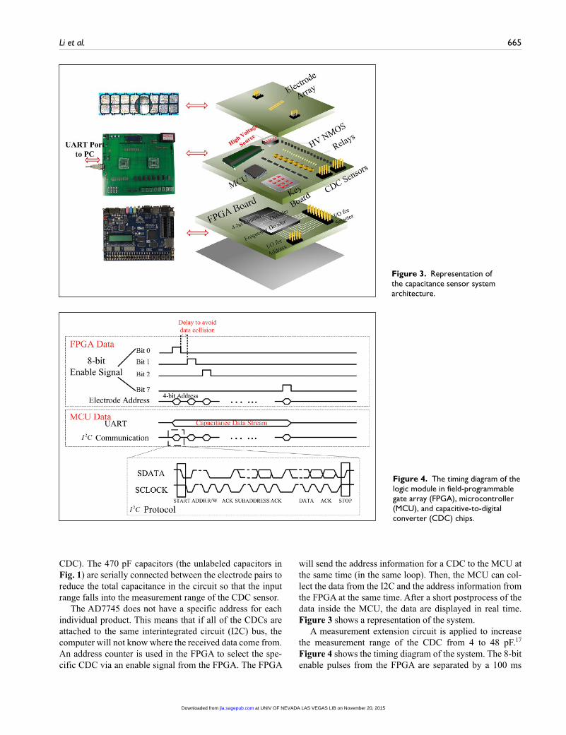
The MOSFETs in Figure 1 are used for controlling the high-voltage signals connected to the electrode array. Figure 3 shows the capacitance sensor system architecture. Relays are needed to isolate the CDC probes from the elec-trodes (a high voltage cannot be applied directly to the
Figure 1. System-level design of the droplet position monitor.
Figure 2. Diagrams of (A) single-plate operation; and (B) dual-plate operation.
at UNIV OF NEVADA LAS VEGAS LIB on November 20, 2015jla.sagepub.comDownloaded from
Li et al. 665
CDC). The 470 pF capacitors (the unlabeled capacitors in Fig. 1) are serially connected between the electrode pairs to reduce the total capacitance in the circuit so that the input range falls into the measurement range of the CDC sensor.
The AD7745 does not have a specific address for each individual product. This means that if all of the CDCs are attached to the same interintegrated circuit (I2C) bus, the computer will not know where the received data come from. An address counter is used in the FPGA to select the spe-cific CDC via an enable signal from the FPGA. The FPGA
will send the address information for a CDC to the MCU at the same time (in the same loop). Then, the MCU can col-lect the data from the I2C and the address information from the FPGA at the same time. After a short postprocess of the data inside the MCU, the data are displayed in real time. Figure 3 shows a representation of the system.
A measurement extension circuit is applied to increase the measurement range of the CDC from 4 to 48 pF.17 Figure 4 shows the timing diagram of the system. The 8-bit enable pulses from the FPGA are separated by a 100 ms
Figure 3. Representation of the capacitance sensor system architecture.
Figure 4. The timing diagram of the logic module in field-programmable gate array (FPGA), microcontroller (MCU), and capacitive-to-digital converter (CDC) chips.
at UNIV OF NEVADA LAS VEGAS LIB on November 20, 2015jla.sagepub.comDownloaded from

666 Journal of Laboratory Automation 20(6)
delay to avoid the data collision. The electrode address is counted by an embedded counter in the FPGA. The MCU can collect the capacitance data and the corresponding elec-trode address at the same time.
Results and Discussion
The threshold voltage to move the droplets depends on the contact angle changes of the droplets.18 How the contact angle of water droplets changes with various voltages and frequencies was investigated using the developed platform. The results are seen in Figure 5. It is obvious that the con-tact angle change is dependent on both the voltage level and frequency of the applied pulse signal. When the voltage is lower than 100 V, the contact angle change is negligible. But when the voltage becomes larger than 200 V, the con-tact angle can change up to 40° when a 1 kHz pulse is used. Based on these results, the droplet starts to be actuated at 200 V. In general, droplet dynamics is determined by diverse factors such as fluid density, the initial and deformed con-tact angles, contact angle hysteresis, and frictions.19 Keeping other factors as constants, the contact angle change and the added voltage change will affect the droplet actua-tion significantly. The droplet contact angles are determined by the thermodynamic equilibrium conditions, which are described as:20
cos cosθ θγ
= +oV
d
2
2 12
where θo is the contact angle without external voltage applied; θ is the contact angle with external voltage V applied; is the dielectric constant of the droplet–substrate
environment; γ12 is the surface tension; and d is the thick-ness of the dielectric layer. The dielectric constant of peanut oil is peanut oil− ≈ 3 1. ; the dielectric constant of silicone oil used in previous studies is silicone oil− ≈ 2 7. .21 As shown in Figure 6, the total capacitance can be treated as the parallel of the oil capacitance, the Saran Wrap capacitance, and other environment capacitances. So a larger oil dielectric constant leads to an increased overall capacitance of the environment and lowers down the threshold voltage when achieving the same contact angle changes.
The postprocessed PCB array presented here can move droplets (~30 µL, and thus much smaller droplets that are still capable of bridging the array’s electrodes) with a much smaller voltage and frequency than previously reported.15 According to the discussion above, using peanut oil instead of silicone oil can decrease the threshold voltage.
The CDC sensor array is evaluated when the droplet is located at different positions. The capacitances cp1–cp8 in Figure 7 represent the capacitance of the eight electrode pairs. The droplet position has only three statuses: fully occupied, half occupied, and “off” the electrode. The soft-ware can distinguish if the droplet is on the left or on the right by checking the address. This is why an FPGA is used (i.e., to hold the address information).
Note that the capacitance measured uses a pure-water droplet that is higher than the capacitance of other types of droplets. The large dielectric constant of water means that ionic bonds of the solute will tend to dissociate in water yielding solutions containing ions. Water as a solvent opposes the ionic force between the ions. Water molecules have four hydrogen bonds, and this structure of water greatly resists the random thermal motions. This hydrogen bonding is responsible for its large dielectric constant.
The variation between CDCs (relative consistency) was also investigated. For example, there is a deviation of up to 200 fF between the CDC sensors when testing the same stan-dard ceramic capacitor. The data seen in Figures 8, 9, and 10 were measured with circuits built with connection wires and bread boards. The CDC sensors are mounted on different SOIC-16 SMT adapters. Subtle parasitic capacitance changes
Figure 5. Contact angle changes of a 3 µL water droplet. The contact angle change is affected by the activate pulse frequency and voltage level.
Figure 6. Capacitance model for the droplet–substrate environment.
at UNIV OF NEVADA LAS VEGAS LIB on November 20, 2015jla.sagepub.comDownloaded from

Li et al. 667
are created by the differences of adapters and wires and the fabrication process of the CDC chip.
One may also be concerned with the consistency of the CDC when it is measuring the same capacitor over and over again (the noise in the measurement). Figure 10 shows the stability of one CDC sampling the same capacitor. The deviations are small and negligible (around 10 fF) for this application. The deviation seen in Figure 8 is in the 200 fF range, but the deviation when testing standard ceramic capacitors is much smaller. This is because the deviation of the droplet system may be caused by the subtle displace-ment and shape of the droplet, undistinguishable with the naked eye (changes of hundreds of femtofarads may occur).
As shown in Figure 11, the droplet-sensing system can distinguish the three statuses (fully occupied, half occupied, and “off”) for single droplets or multiple droplets. If the
position of the droplets changed, then the software can update the position information in the matrix instantly and reflect the new positions in the animation. The capacitance data come together with the electrode address to the MCU and then are transmitted through the universal asynchro-nous receiver/transmitter port to the PC, so the computer will not make a mistake about the ownership of the capaci-tance data.
When the droplet is moving, the system can update and reflect the position information dynamically (Fig. 12). An oil environment is preferred because the droplet will have a larger contact angle change with voltage pulses added to the corresponding electrode.
The main speed bottleneck of the entire process is the analog-to-digital conversion process inside the CDC. So if the capacitance becomes larger, the response time for the CDC will be even slower because of the longer charging time. This will be an issue if using a single MCU to scan over a large electrode array. Further work will focus on developing a distributed system that uses more MCUs to avoid this bottleneck. Obviously, the time spent on using a single MCU to scan the array is highly dependent on the size of the array. The response time can be further reduced by focusing on the data bus width. The current CDC is transmitting data using the I2C bus in which only one wire is used. Using a parallel bus can improve the data transmis-sion rate and thus the response time.
Normally, electrowetting is implemented in an oil envi-ronment because the droplet in the oil has a much larger contact angle than in an air environment. There are several studies directed at using an air environment to actuate the liquids by using smaller electrodes and more hydrophobic surfaces.22 If the contact angle of the droplet on the elec-trode is large enough in air, then the oil environment can be avoided. Pumping and collecting the droplets are also required for the staining experiment. Some researchers are using a reservoir to store a larger amount of liquid to pro-vide droplets to the electrodes.13,23 For disposing wasted liquid, however, the electrowetting devices need to be assembled with a capillary pump as described before.24–26 Microfluidic chips designed based on the techniques
Figure 8. Diagram of (A) cp1, (B) cp2, and (C) cp3 values at different positions.
Figure 7. Diagram of the capacitance of each electrode pair. The five droplets in this figure are specifically used to represent the five different positions of the droplets on the first three electrode pairs that help explain the parameters in Figure 8.
at UNIV OF NEVADA LAS VEGAS LIB on November 20, 2015jla.sagepub.comDownloaded from

668 Journal of Laboratory Automation 20(6)
present in this study may have significant potential in ani-mal tissue staining experiments.
Conclusions
The concept of using commercially capacitive IC chips to locate droplets on a microfluidic substrate (“capacitive vision”) has been reported. The fast prototyping PCB-based microfluidic systems are easy to fabricate and cus-tomize. A lower-threshold voltage than previously reported to actuate large droplets in a single-plate elec-trode array was achieved. The capacitance detection cir-cuit developed in this work was used to locate single or multiple droplets, and then statically and dynamically display the position of the droplets in real time on a PC. Improvements in the response time of the sensor for large electrode arrays were proposed and discussed. Potential applications of this system in the batch processing of immunohistochemistry animal tissue staining experi-ments were also discussed.
Figure 11. Static droplet position detection in air environment for the following: (A1) one droplet bridges two electrodes; (A2) two droplets bridge two electrodes; (B1) one droplet bridges four electrodes; and (B2) one of the two droplets bridges four electrodes. The droplets are put on the electrode array by pipette.
Figure 9. Diagram of the capacitance of the standard ceramic capacitors measured by AD7745 and Bench LCR/ESR Meter (B&K Precision Corp, Yorba Linda, CA). The diagram shows the comparison of the measurements of standard ceramic capacitors with the values of (A) 10 pF, (B) 15 pF, (C) 22 pF, (D) 33 pF, and (E) 47 pF.
Figure 10. Diagram of evaluating one capacitive-to-digital converter (CDC) with a standard ceramic capacitor.
at UNIV OF NEVADA LAS VEGAS LIB on November 20, 2015jla.sagepub.comDownloaded from

Li et al. 669
Acknowledgments
The authors thank Jing Chen at Northeastern University, Shenyang, China, and Roger Chen from Genia Chip, Inc., for their sugges-tions and discussions.
Declaration of Conflicting Interests
The authors declared no potential conflicts of interest with respect to the research, authorship, and/or publication of this article.
Funding
The authors received no financial support for the research, author-ship, and/or publication of this article.
References
1. Gong, J.; Kim, C. Direct-Referencing Two-Dimensional-Array Digital Microfluidics Using Multilayer Printed Circuit Board. J. Microelectromech. Syst. 2008, 17, 257–264.
2. Abdelgawad, M.; Wheeler, A. R. Rapid Prototyping in Copper Substrates for Digital Microfluidics. Adv. Mater. 2007, 19, 133–137.
3. Li, Y.; Chen, R.; Baker, R. J. A Fast Fabricating Electro-wetting Platform to Implement Large Droplet Manipulation. In Proceedings of the 57th Midwest Symposium on Circuits and Systems. IEEE: College Station, 2014.
4. Li, Y.; Li, H.; Baker, R. J. Volume and Concentration Identification by Using an Electrowetting on Dielectric Device. In Proceedings of the 10th IEEE Dallas Circuits and Systems Conference. IEEE: Richardson (TX), 2014.
5. Basu, A. S. Droplet Morphometry and Velocimetry (DMV): A Video Processing Software for Time-Resolved, Label-Free Tracking of Droplet Parameters. Lab Chip. 2013, 13, 1892–1901.
6. Ren, H; Fair, R. B.; Pollack, M. G. Automated On-Chip Droplet Dispensing with Volume Control by Electro-wetting Actuation and Capacitance Metering. Sens. Actuators B. 2004, 98, 319–327.
7. Schertzer, M. J.; Ben-Mrad, R.; Sullivan, P. E. Using Capacitance Measurements in EWOD Devices to Identify Fluid Composition and Control Droplet Mixing. Sens. Actuators B. 2010, 145, 340–347.
8. Murran, M. A.; Najjaran, H. Capacitance-Based Droplet Position Estimator for Digital Microfluidic Devices. Lab Chip. 2012, 12, 2053–2059.
9. Ren, H.; Fair, R. B. Micro/Nano Liter Droplet Formation and Dispensing by Capacitance Metering and Electrowetting Actuation. In Proceedings of the 2nd IEEE Conference on Nanotechnology. IEEE: Washington (DC), 2002.
10. Chen, J. Z.; Darhuber, A. A.; Troian, S. M.; et al. Capacitive Sensing of Droplets for Microfluidic Devices Based on Thermocapillary Actuation. Lab Chip. 2004, 4, 473–480.
11. Niu, X.; Zhang, M.; Peng, S.; et al. Real-Time Detection, Control, and Sorting of Microfluidic Droplets. Biomicrofluidics. 2007, 1, 044101.
12. Elbuken, C.; Glawdel, T.; Chan, D.; et al. Detection of Microdroplet Size and Speed Using Capacitive Sensors. Sens. Actuators A. 2011, 171, 55–62.
13. Gong, J. All-Electronic Droplet Generation on-Chip with Real-Time Feedback Control for EWOD Digital Microfluidics. Lab Chip. 2008, 8, 898–906.
14. Avramov-Zamurovic, S.; Lee, R. D. A High-Stability Capacitance Sensor System and Its Evaluation. IEEE Trans. Instrum. Meas. 2009, 58, 955–961.
15. Abdelgawad, M.; Wheeler, A. R. Low-Cost, Rapid Prototyping of Digital Microfluidics Devices. Microfluid. Nanofluid. 2008, 4, 349–355.
16. Park, J. K.; Lee, S. J.; Kang, K. H. Fast and Reliable Droplet Transport on Single-Plate Electrowetting on Dielectrics Using Nonfloating Switching Method. Biomicrofluidics. 2010, 4, 024102.
17. Analog Devices. Manufacturer Specifications: Extending the Capacitive Input Range of AD7745/AD7746. Analog Devices: Norwood (MA), 2009.
18. Moon, H.; Cho, S. K.; Garrell, R. L.; et al. Low Voltage Electrowetting On-Dielectric. J. Appl. Phys. 2002, 92, 4080–4087.
19. Schertzer, M. J.; Gubarenko, S. I.; Ben-Mrad, R.; et al. An Empirically Validated Analytical Model of Droplet Dynamics in Electrowetting on Dielectric Devices. Langmuir. 2010, 26, 19230–19238.
20. Kang, K. H. How Electrostatic Fields Change Contact Angle in Electrowetting. Langmuir. 2002, 18, 10318–10322.
21. Oommen, T. V. Vegetable Oils for Liquid-Filled Transformers. IEEE Elect. Insul. Mag. 2002, 18, 6–11.
22. Shih, S. C.; Yang, H.; Jebrail, M. J.; et al. Dried Blood Spot Analysis by Digital Microfluidics Coupled to Nanoelectrospray Ionization Mass Spectrometry. Anal. Chem. 2012, 84, 3731–3738.
23. Cho, S. K.; Moon, H.; Kim, C. Towards Digital Microfluidic Circuits: Creating, Transporting, Cutting and Merging Liquid Droplets by Electrowetting-Based Actuation. J. Microelectromech. Syst. 2003, 12, 70–80.
24. Kim, H.; Jebrail, M. J.; Sinha, A.; et al. A Microfluidic DNA Library Preparation Platform for Next-Generation Sequencing. PloS ONE. 2013, 8, e68988.
25. Kim, H.; Bartsch, M. S.; Renzi, R. F.; et al. Automated Digital Microfluidic Sample Preparation for Next-Generation DNA Sequencing. J. Lab. Autom. 2011, 16, 405–414.
26. Thaitrong, N.; Kim, H.; Renzi, R. F.; et al. Quality Control of Next-Generation Sequencing Library through an Integrative Digital Microfluidic Platform. Electrophoresis. 2012, 33, 3506–3513.
Figure 12. Dynamic detection of the droplet position in an oil environment. It is hard to see the transparent water droplet edges in an oil environment (droplets in Fig. 11 are moved in air) under the camera light-emitting diode (LED) lights, so red contour of the droplet is added to (A1)–(A4).
at UNIV OF NEVADA LAS VEGAS LIB on November 20, 2015jla.sagepub.comDownloaded from