Keeping a Crowd Safe On the Complexity of Parameterized Verification

JOURNAL OF INFORMATION SCIENCE AND ENGINEERING 24, 859-873 (2008)
859
A Low Complexity Fingerprint Verification Algorithm with Reduced Hardware Resources*
JIA-HONG DAI AND CHING-HAN CHEN+
Department of Electrical Engineering I-Shou University
Kaohsiung, 840 Taiwan +Department of Computer Science and Information Engineering
National Central University Taoyuan, 320 Taiwan
A low complexity fingerprint verification scheme with ultra-compact hardware re-
sources requirement is presented in the paper. Firstly, the fingerprint image is captured and performed noise canceling by a binary low-pass filter. Secondly, the displacement of the fingerprint pattern is estimated by means of directional image matching, and then circular profile features of the fingerprint are extracted for verification matching. Finally, the proposed method is implemented in an 8-bits microcontroller run at 25MHz, equipped only with 12 Kbytes program code memory and 35 Kbytes data memory. It is very favorable for prototyping the low-cost fingerprint verification SoC (System-On- Chip). Keywords: biometrics, fingerprint, verification, embedded system, SoC, 8051
1. INTRODUCTION
The biometric system is a pattern recognition system, which automatically differen-tiates people on the basis of individual biometric features, such as voice, hand geometry, fingerprint and iris patterns of the eyes. It generally includes three components: data ac-quisition, feature extraction and decision-making. The biometric data may come from specific sets of physiological (like fingerprint, face, etc.) or behavioral characteristics (voice, gait, etc.). The integration of biometrics for person authentication system pro-vides the advantages of increasing the system’s security and reliability [1].
A biometric system can be run in two modes [2]: identification or verification. Iden-tification is the process of finding out an identity from a set of enrolled template patterns. A pattern may be identified through matching the input pattern with every enrolled tem-plate. According to the similarity between the pattern and the enrolled template, a match-ing score is obtained. The template with the maximal matching score is assigned as the identified person.
As for the verification, it is the process to verify the input pattern with a template of which the person’s identity has been claimed a priori. Like the identification, the similar-ity between the input pattern and the enrolled template is checked to provide the exclu-sive Yes/No output.
Received October 3, 2006; revised February 7 & April 20, 2007; accepted June 27, 2007. Communicated by Pau-Choo Chung. * The earlier version of this paper was presented at IEEE International Symposium on Consumer Electronics
(ISCE), Macau, June 14-16, 2005.

JIA-HONG DAI AND CHING-HAN CHEN
860
Among different biometrics techniques, fingerprint is the most widely used because of its uniqueness, ease of collection and public acceptance [3]. Since 1960, a large num-ber of criminal and civilian fingerprint-based applications are studied and developed. In these cases, the unknown fingerprint has to be recognized among numerous fingerprint images stored in the database. These systems generally adopted identification mode. On the contrast, for most portable security applications like pen drive, mobile phone, PDA and smart card, the verification mode might be more attractive than identification mode due to the nature of individualized use. The fingerprint could serve as a secret key which is not likely to be stolen.
Most fingerprint recognition systems rely on minutiae-based representation. Minu-tiae are specific points in a finger image. There are two main types, known as ridge end-ings and bifurcations [4]. An excellent review of minutiae-based fingerprint verification method can be found in Yager and Amin [5]. This method is characterized by high rec-ognition precision as well as high algorithmic complexity. Therefore, it is generally im-plemented in a desktop PC or a high performance processor. Its integration in a portable application system constitutes a big challenge because of the strict constraints related to size, power and performance of the processor. But we still can find embedded fingerprint verification systems. Yang and Verbauwhede [7] have developed an embedded finger-print verification system for a “ThumbPod” device. They implement the complex signal preprocessing step on a powerful card reader, and only the matching step is executed on the embedded device. With specific hardware acceleration and memory optimization, the minutiae extraction and the matching process can be executed in a 50MHz LEON-2 processor with 483KB memory used. In the work of Pan et al. [8], the fingerprint verifi-cation is implemented in a 32-bit ARM7TDMI with 64KB ROM, 8KB RAM and 32KB EEROM for smart card application. Tang et al. [9] use a 206 MHz StrongARM-based PDA to implement the fingerprint verification algorithm. Rikin et al. [10] developed a 100MHz DSP board with 32KB memory.
In this paper, we devote to elaborate a new fingerprint verification algorithm in which the computational complexity and memory requirement are extremely reduced. Aiming at the portable security applications, the proposed algorithm is more adequate than conventional methods for implementation with restricted hardware resources.
The rest of this paper is organized as follows. Section 2 reviews the conventional minutiae-based method as a comparative fingerprint verification algorithm. Section 3 explains the proposed fingerprint verification algorithm. Section 4 describes the imple-mentation details using an 8051 microcontroller with reduced memory requirement. The performance evaluation and comparisons are presented as well in this section. The con-clusions are given in section 5.
2. MINUTIAE-BASED FINGERPRINT VERIFICATION
The typical minutiae-based fingerprint verification system generally consists of three fundamental modules [4, 11, 12]: (1) pre-processing module which includes image enhancement, binarization, and thinning process for the refinement of acquired finger-print image; (2) minutiae extraction module which locates all the branching points and bifurcation points in the fingerprint image; and (3) minutiae matching module which

A COMPACT FINGERPRINT VERIFICATIONS SYSTEM
861
compares the extracted minutiae set with those of enrolled template. At the module of pre-processing, the directional band-pass Gabor filter-bank approach is one of the most effective and mathematically elegant techniques to date for fingerprint image enhance-ment. It was proposed for the first time by Hong, Wan, and Jain [11]. Gabor filters have both frequency-selective and orientation-selective properties in frequency domain. It is composed of a set of coefficients in two-dimentional structure to remove effectively the noise and preserve parallel ridge/valley pattern. Minutiae are extracted generally from thinned skeleton images [13, 14]. Before this process, the binarization on enhanced gray image and thinning operation have to be executed first. The information of extracted mi-nutiae includes location, orientation and type of minutiae. It will be used for the fol-low-up matching procedure.
Minutiae matching consists of two processes which are alignment and minutiae pairing [15]. In order to match the extracted minutiae set with unknown direction and displacement, we must try to find the differences of direction and displacement between the template fingerprint and the one to be verified. In this stage, the affine transforms such as translation and rotation are estimated. According to the estimated parameters, two minutiae sets are aligned [16]. Once the alignment is completed accurately, matching stage consists in computing the Euclidian distance of two point patterns. A matching score is then obtained.
We resume the minutiae-based fingerprint verification scheme in Fig. 1.
(a) Enrollment.
(b) Verification.
Fig. 1. Minutiae-based fingerprint verification scheme.
3. LOW COMPLEXITY FINGERPRINT VERIFICATION SCHEME
The minutiae-based fingerprint verification algorithm described in section 2 pos-sesses high computational complexity and hardware resources requirement. It is disad-vantage for resource-constraint portable application. Aiming at this problem, we propose a low complexity fingerprint verification scheme as shown in Fig. 2. It has the objectives of reducing the computational complexity and minimizing the memory requirement at sufficient recognition performance.

JIA-HONG DAI AND CHING-HAN CHEN
862
Low Pass Filter Block Direction
Enroll Fingerprint Circular Profile
Feature Extraction
Enrolled Direction Feature
Enrolled Circular Profile Feature
(a) Enrollment.
Low Pass Filter
Block Direction
Fingerprint to verify
Displacement Detection
Circular Matching
00 , yx ΔΔ
Enrolled Circular Profile FeatureYes / No
Enrolled Direction Feature
(b) (b) Verification.
Fig. 2. Proposed fingerprint verification scheme.
We use the fingerprint sensor AFS2 from AuthenTec Co. [18] whose resolution is
250 DPI with image size 128 × 128 pixels, and each pixel has eight gray-levels repre-sented by three bits. The sensor’s output can be adjusted as one-bit output for the purpose of efficiency and complexity reduction.
The proposed fingerprint verification scheme ignores, at the first stage, the ridge and rotation characters to find out a coarse displacement from the direction feature. Ac-cording to the displacement, the circular matching module considers the details of fin-gerprint ridge to perform more accurate matching. 3.1 Low Pass Filter
The original image I(x, y) ∈ {0, 1}, 0 ≤ x, y < W from fingerprint sensor AFS2 is a binary image (see Fig. 3 (a)). A multiplierless low-pass filter is used to reduce high fre-quency noises and to enhance the ridge pattern of a fingerprint image. The filtered image is obtained by:
1, if ( ( , ) )( , )
0, otherwisesum x y T
L x y>⎧
= ⎨⎩
(1)
( , ) ( , )L L
h L h L
w w
h hx w y w
sum x y I x x y y=− =−
= + +∑ ∑ (2)
where (2wL + 1) is the filter size, T is a given threshold, and L(x, y) is the output filtered image (see Fig. 3 (b)). The ‘1’ represents the ridge (marked black), and ‘0’ the valley (marked white).

A COMPACT FINGERPRINT VERIFICATIONS SYSTEM
863
(a) Image captured from the sensor. (b) Filtered image.
Fig. 3. Low pass filtering.
3.2 Feature Extraction
In the proposed scheme, the fingerprint feature is represented by block direction image and circular profile in order to reduce computational complexity of conventional minutiae extraction procedure.
3.2.1 Block direction computing
This process separates L(x, y) into sub-blocks with b × b pixels. Considering a pixel block structure where the target pixel X = L(x, y) with eight nearest surrounded X0, X1, …, X7 are arranged as shown in Fig. 4.
X0 X1 X2 X7 X X3 X6 X5 X4
Fig. 4. Pixel block structure.
We use a set of logic Eqs. (3)-(6) to compute the directions of each target pixel.
d0 = X ∩ X7 ∩ X3 (3) d1 = X ∩ X1 ∩ X5 (4) d2 = X ∩ X2 ∩ X6 (5) d3 = X ∩ X0 ∩ X4 (6)
di ∈ {0, 1} represents whether there is direction i of pixel. i ∈ {0, 1, 2, 3} is the index of four directions (0°, 90°, 45°, − 45°). Then direction of each block can be obtained by:
( , ) (max ( , )), 0 , 0 , iWD u v direction A u v u w v w wb
⎢ ⎥= ≤ < ≤ < = ⎢ ⎥⎣ ⎦ (7)
and 1 1
0 0( , ) ( , )
b b
b b
i i b bu v
A u v d u b u v b v− −
= == ⋅ + ⋅ +∑ ∑ (8)
where direction(⋅) is the direction i of the block.

JIA-HONG DAI AND CHING-HAN CHEN
864
Fig. 5. 32 × 32 pixels block direction image.
Fig. 5 shows the block direction image obtain from Fig. 3 (b) when b = 4. Because
the block size is b × b, the direction image area is reduced to 1/b2 of the source image area. So it benefits the reduction of the computational operation of the succeeding dis-placement detection procedure. 3.2.2 Circular profile feature extraction
This process extracts circular features of a fingerprint image by m co-centric circles.
The circular features can be manipulated as a 1-D array in memory. It can therefore avoid complex memory addressing operation such as multiply-addition or shifting.
(a) Example of circular profile with NBP = 8. (b) Co-centric circular profiles.
Fig. 6. Circular profile features.
Fig. 6 (a) shows an example of circular profile. All the sample pixels of the co-cen-
tric circular profile are the same. Assign a coordinate set (Δx, Δy) as the centre of co- centric circular profiles and the radius of circular profile rm (see Fig. 6 (b)). The coordi-nate set O of circular profile is defined by:
{( , ) | ; ; 0 , }mn mn m n mn mnO x y r x y Wθ= ∈ℜ ∈Θ ≤ < (9)
where,
cos2
sin2
mn m n
mn m n
Wx r x
Wy r y
θ
θ
⎧ = + + Δ⎪⎪⎨⎪ = + + Δ⎪⎩
(10)
{ |1 }m BCr m Nℜ = ≤ ≤ (11)

A COMPACT FINGERPRINT VERIFICATIONS SYSTEM
865
{ |1 },n BPn NθΘ = ≤ ≤2
nBP
nNπθ = ⋅ (12)
(Δx, Δy) is the displacement between the centre of circular profile and the centre of fin-gerprint image. If there is no a priori knowledge or heuristic about the position of refer-ence point of the fingerprint, (Δx, Δy) is assigned to (0, 0).
rm is the radius of the mth circular profile. θn is the sampling degree of the nth sample pixel of circular profile. NBC is the number of circles. NBP is the number of sample pixels on a circular profile.
The circular profile features (Fig. 6 (b)) of the fingerprint are defined by:
P = {pmn⏐pmn = L(xmn, ymn), (xmn, ymn) ∈ O}. (13)
3.3 Feature Matching
3.3.1 Displacement detection
The displacement can be detected by comparing two block direction images (see Fig. 7). We compute the mean error of the overlapped area of the enrolled block direction image DE and the image to be verified DC. The mean error is defined as:
2 2
1 1
( ) ( )
( ) ( )
1( , )( | |)( | |)
( ( , ), ( , ))f u f v
C Eu f u v f v
MeanErr u vw u w v
cmp D u v D u u v vΔ Δ
= Δ = Δ
Δ Δ =− Δ − Δ
⋅ − Δ − Δ∑ ∑ (14)
where,
otherwise.),0(if
,,
0)(1
>
⎩⎨⎧
=zz
zf (15)
otherwise.),0(if
,,
11
)(2
>
⎩⎨⎧
−+−
=z
zww
zf (16)
Fig. 7. Displacement detection.
JIA-HONG DAI AND CHING-HAN CHEN
866
0, if ( ( , ) ( , )),( ( , ), ( , ))
1, otherwise.C E
C ED u v D u u v v
cmp D u v D u u v vΔ Δ
Δ Δ= − −⎧
− − = ⎨⎩
(17)
The displacement (Δumin, Δvmin) between DE and DC is obtained by (Δumin, Δvmin,) = {(Δu, Δv) | min(MeanErr(Δu, Δv)); − q ≤ Δu, Δv ≤ q} (18) The (Δumin, Δvmin) is transformed to raw image scale by using:
0 min
0 min.
x b uy b v
Δ = ⋅Δ⎧⎨Δ = ⋅Δ⎩
(19)
We get the displacement (Δx0, Δy0) between the enrolled image LE(x, y) and the im-age to be verified Lc(x, y), which is the indispensable information for the circular match-ing procedure. 3.3.2 Circular matching
After the enrolled circular profile feature PE and the displacement (Δx0, Δy0) are ob-
tained separately, the following procedure will conduct to the final matching: Step 1: Initialize. Let Δn (− α ≤ Δn ≤ α) be the rotation parameter and ρx, ρy (−β ≤ ρx,
ρy ≤ β) be the shifted parameter, α = 5, β = 5 are adopted in our experiments. Step 2: Loop for Δn and (ρx, ρy). Change the rotation and the shifted parameters, then
execute steps 3 and 4. Step 3: Compute PC. Extract the circular profile feature PC from LC using (Δx0, Δy0)
and (ρx, ρy) by
0 0
{ | ( , ), ( , ) , , }.
C Cmn Cmn C mn mn mn mn
x y
P p p L x y x y Ox x y yρ ρ
= = ∈
Δ = Δ + Δ = Δ + (20)
Step 4: Match LC with enrolled PE. PC and PE are binary string, use Eq. (21) to calcu-late Hamming distance dH(Δn, ρx, ρy). The symbol ⊗ denote the operation of Hamming distance calculation.
( , , ) E CH x y
C
P Pd n
Pρ ρ
⊗Δ = (21)
Keep the minimum Hamming distance dH as dmin for each cycle of loop. If all possible values of Δn and (ρx, ρy) are tested, execute step 5.
Step 5: Compare dmin with dT. dT is a threshold. If dmin is less than dT, the IC is accepted
as IE identity.
A rotated fingerprint image against the enrolled image can be matched by testing different Δn. Thanks to the rotation-invariant property of circular profile feature, the

A COMPACT FINGERPRINT VERIFICATIONS SYSTEM
867
(a) (b) (c)
Fig. 8. Example of circular profile matching. (a) Enrolled circular profile feature; (b) Fingerprint to be verify and the extracted circular profile feature; (c) Feature matching with Δn = − 1, ρx = 3, ρy = − 4.
matching process has high flexibility to adjust between the matching time and rotation tolerance. The larger the range of Δn is, the longer the matching time will take, which, however, enables a larger rotation tolerance. Fig. 8 shows an example. When NBC = 4, NBP = 90 and the displacement detected (Δx0, Δy0) = (12, 14), two fingerprints are matched by circular profile feature as shown in Fig. 8.
4. IMPLEMENTATION AND PERFORMANCE EVALUATION
4.1 Algorithmic Performance Evaluation In view of validation of functionality and comparison, we implement firstly the con-
ventional minutiae-based algorithm described in section 2 and the proposed algorithm in Pentium 4/2.5GHz desktop PC.
The performance of fingerprint verification is evaluated by means of FAR (False Acceptance Rate) curve, FRR (False Rejection Rate) curve and EER (Equal Error Rate) [17]. FAR is defined as the probability of an impostor being accepted as a genuine indi-vidual. FRR is defined as the probability of a genuine individual being rejected as an impostor. Both FAR and FRR are regarded as the functions of the threshold used to com-pare the matching score make the decision. The matching score is from the expected probability that a sample declared to match a template. Therefore, a small FRR usually results in a larger FAR, when a smaller FAR usually implies a larger FRR. In general, the term of FAR is very important. Because the value of FAR is zero, it implies that no im-postor is accepted as a genuine individual. A specific point is obtained when FAR and FRR coincide, the so-called EER (equal error rate). The performance of a biometric veri-fication system is estimated with the EER. A low equal error rate value reveals a high verification accuracy of the biometric system.
In our experiment, we use a semiconductor-type fingerprint sensor AFS2 from Au-thenTec Co. [18] to capture 594 fingerprint images [20] from 54 fingers, 11 images for each finger. The acquisition of fingerprint image is under the normal working environ-ment and normal user mode. As stated by Maio et al. [17], in this situation, the maximum rotation of image is approximately in the range [− 15°, 15°]. Some sample images are shown in Fig. 9. For each finger, a fingerprint image is randomly selected as the regis-tered image and the rest as the testing images. The verification is performed respectively

JIA-HONG DAI AND CHING-HAN CHEN
868
Fig. 9. Sample images extracted from experimental fingerprint image database (The first three col-
umns are the right hand fingerprints. The first row is thumb. The second row and the third row are pointing finger. The last row is middle finger).
Fig. 10. Performance comparison between minutiae-based algorithm and the proposed algorithm.
The subscript 1 represents the proposed algorithm; subscript 2 represents the minutiae- based algorithm.
Table 1. Efficiency comparison between minutiae-base algorithm and the proposed al-gorithm.
Execution time (in msec) Preprocessing Feature
Extraction Matching Total
Minutiae-based 7.3 3.5 2.5 13.3 Proposed Algorithm 0.325 0.67 0.245 1.24
A COMPACT FINGERPRINT VERIFICATIONS SYSTEM
869
by the conventional minutiae-based algorithm and the proposed algorithm. The verifica-tion performance is shown in Fig. 10. Table 1 presents the comparison of their execution time. With a little sacrifice of verification performance (against minutiae-based), the pro-posed algorithm is far more efficient than minutiae-based fingerprint verification algo-rithm.
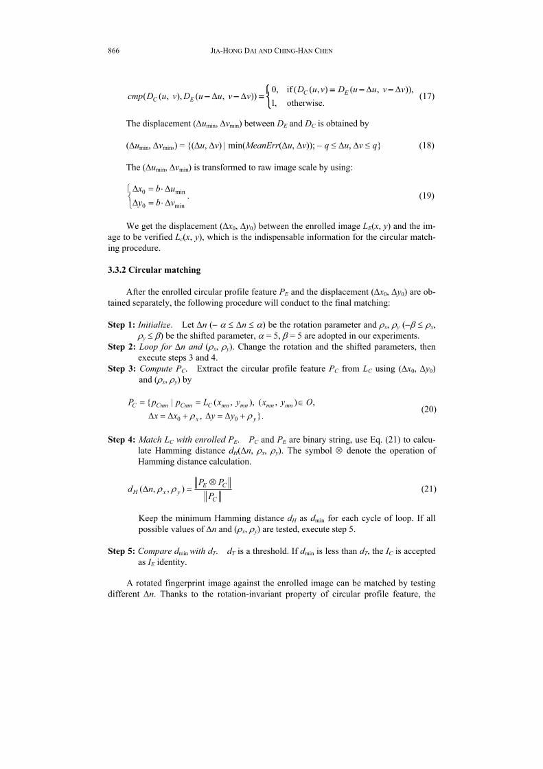
Some false accepted results (Fig. 11) are due to the displacement detection module assumed two fingerprint images from the same finger (but it is not real in fact), therefore the displacement value is wrong and two circular profile features are similar.
(a) (b)
Fig. 11. The false accepted samples in the fingerprint database.
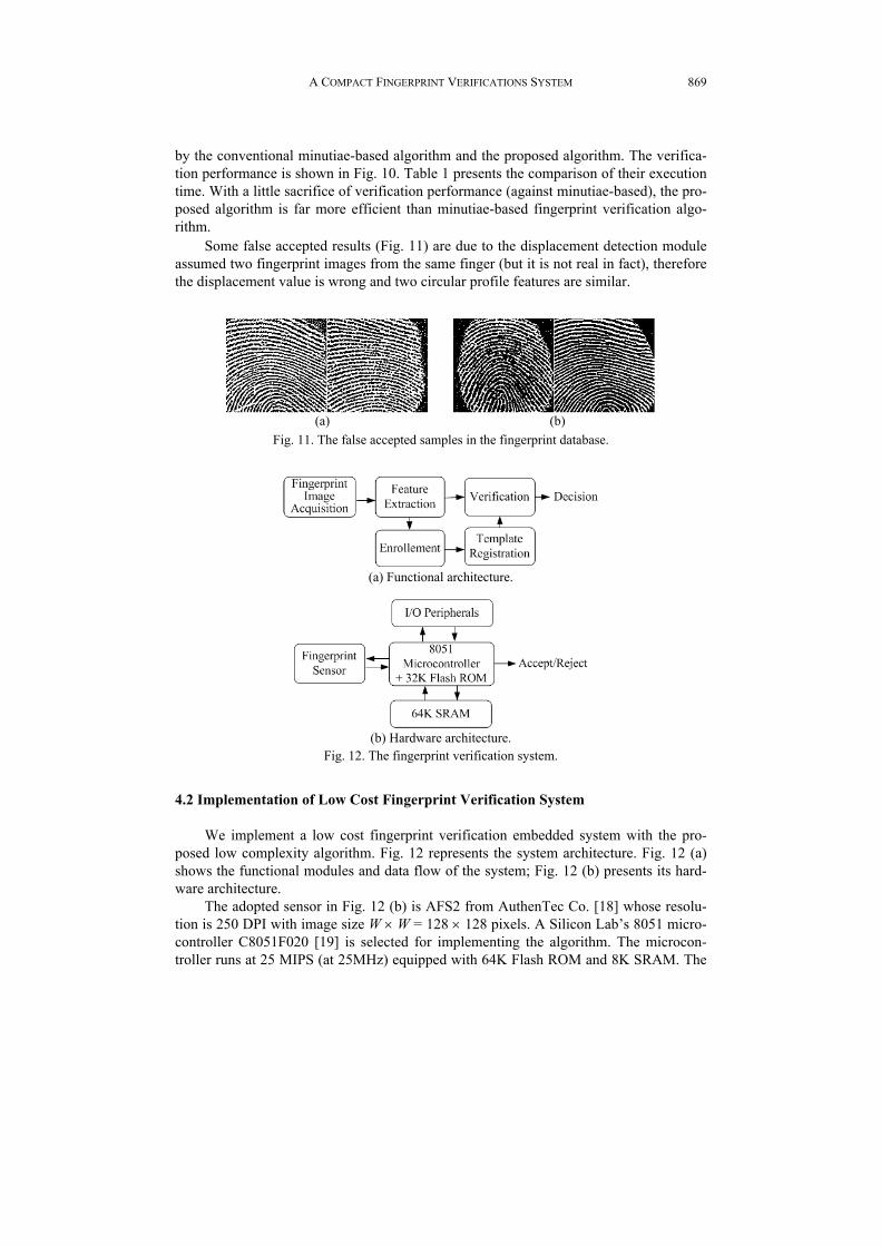
(a) Functional architecture.
(b) Hardware architecture.
Fig. 12. The fingerprint verification system.
4.2 Implementation of Low Cost Fingerprint Verification System
We implement a low cost fingerprint verification embedded system with the pro-posed low complexity algorithm. Fig. 12 represents the system architecture. Fig. 12 (a) shows the functional modules and data flow of the system; Fig. 12 (b) presents its hard-ware architecture.
The adopted sensor in Fig. 12 (b) is AFS2 from AuthenTec Co. [18] whose resolu-tion is 250 DPI with image size W × W = 128 × 128 pixels. A Silicon Lab’s 8051 micro-controller C8051F020 [19] is selected for implementing the algorithm. The microcon-troller runs at 25 MIPS (at 25MHz) equipped with 64K Flash ROM and 8K SRAM. The

JIA-HONG DAI AND CHING-HAN CHEN
870
embedded Flash ROM of microcontroller is used to store the program code as well as the template features of fingerprint. Beside, we add a 64K external SRAM into the embed-ded system as an image buffer. The output of verification module provides two alterna-tives: accept or reject.
The algorithm is transplanted to 8051 platform then is tuned for optimizing the code size and memory management. After a series of the fine tuning, the code size is reduced to 12 Kbytes and the data memory size occupies only 35 Kbytes. The photograph of the realized complete system is shown in Fig. 13.
(a) Front side shows the fingerprint sensor. (b) Back side shows the 8051 microcontroller
and SRAM. Fig. 13. Realization of low cost embedded fingerprint verification system.
Table 2. Requirement of computational resources.
Module Addition Comparator Shifter division Low-Pass Filter 129541 96901 0 0 Block Direction 210011 228725 0 0
Displacement Detection 25828 10073 2 169 Circular Matching 23491 61393 21600 0
Total 568871 397092 21602 169
Table 3. Execution time at 25 MIPS 8051.
Module Execution Time(sec)Low-Pass Filter 0.01 Block Direction 0.13
Displacement Detection 0.15 Circular Matching 0.6 Total Match Time 0.89
The computational performance is evaluated by means of the number of required
addition, comparison, shift and division operation, as well as the execution time run at 25 MIPS 8051. The result is shown in Tables 2 and 3.

A COMPACT FINGERPRINT VERIFICATIONS SYSTEM
871
Due to the utilization of integer data type and multiplierless operation, the execution speed is substantially accelerated and the code size and the memory size are simultane-ously reduced. This compact implementation encourages the applications of the proposed fingerprint verification algorithm to hardware resources-constraint portable and mobile security. Furthermore, the realized embedded system provides a prototype for imple-mentation of fingerprint verification SoC.
5. CONCLUSION
The proposed low complexity fingerprint verification scheme targets on low cost, hardware restricted embedded applications. Differing from conventional minutiae-based fingerprint verification, our approach uses block direction and circular profile as finger-print feature representation. The purpose of the proposed method is to find out a coarse displacement from direction feature. Thus, the circular matching module will achieve more accurate matching by means of the direction feature. It reduces significantly image buffer requirement and accelerates the memory access speed. The matching procedure consists of displacement detection and circular matching that provide adjustable flexibil-ity of rotation-invariant/matching speed. The proposed algorithm is verified on a desktop PC and compared with the minutiae-based fingerprint verification algorithm. With a little sacrifice of verification performance (EER = 4.27% against minutiae-based EER = 1.64%), the proposed algorithm achieves considerable reduction of computational com-plexity. The proposed algorithm is afterward implemented in an 8-bits 8051 microcon-troller run at 25MHz. As a result of optimization in data type, arithmetic operation and memory management, the program code consumes only 12 Kbytes and the data memory size is 35 Kbytes. The evaluation experiment shows that the proposed algorithm has the advantages of high efficiency as well as very low computational complexity at satisfac-tory verification performance. The realized embedded fingerprint verification system provides a prototype for implementation of low cost fingerprint verification SoC for po-tential mobile security applications.
REFERENCES
1. A. Jain, R. Bole, and S. Panakanti, Biometrics: Personal Identification in Networked Society, Kluwer Academic Publishers, Massachusetts, 1999.
2. P. Komarinski, Automated Fingerprint Identification System, Elsevier Academic Press, Burlington, MA, 2005.
3. A. K. Jain, L. Hong, and R. Bolle, “On-line fingerprint verification,” IEEE Transac-tions on Pattern Analysis and Machine Intelligence, Vol. 19, 1997, pp. 302-314.
4. D. Maio and D. Maltoni, “Direct gray-scale minutiae detection in fingerprints,” IEEE Transactions on Pattern Analysis and Machine Intelligence, Vol. 19, 1997, pp. 27-40.
5. N. Yager and A. Amin, “Fingerprint verification based on minutiae features: a re-view,” Pattern Analysis and Application, Vol. 7, 2004, pp. 94-113.
6. Y. Gil, D. Moon, S. Pan, and Y. Chung, “Fingerprint verification system involving smart card, information security and cryptology,” in Proceedings of International

JIA-HONG DAI AND CHING-HAN CHEN
872
Calendar of Information Science Conferences, 2002, pp. 510-524. 7. S. Yang and I. Verbauwhede, “A real time, memory efficient fingerprint verification
system,” in Proceedings of IEEE Acoustics, Speech, and Signal Processing, 2004, pp. V-189-192.
8. S. B. Pan, D. Moon, Y. Gil, D. Ahn, and Y. Chung, “An ultra-low memory finger-print matching algorithm and its implementation on a 32-bit smart card,” IEEE Transactions on Consumer Electronics, Vol. 49, 2003, pp. 453-459.
9. T. Y. Tang, Y. S. Moon, and K. C. Chan, “Efficient implementation of fingerprint verification for mobile embedded systems using fixed-point arithmetic,” in Pro-ceedings of ACM Symposium on Applied Computing, 2004, pp. 821-825.
10. A. S. Rikin, W. Yiwen, T. Nakada, L. Dongju, T. Isshiki, and H. Kunieda, “Realiza-tion of fingerprint identification module on DSP board,” in Proceedings of Asia-Pa- cific Conference on Circuits and Systems, Vol. 1, 2002, pp. 509-512.
11. L. Hong, Y. Wan, and A. Jain, “Fingerprint image enhancement: algorithm and per-formance evaluation,” IEEE Transactions on Pattern Analysis and Machine Intelli-gence, Vol. 20, 1998, pp. 777-789.
12. K. C. Chan, Y. S. Moon, and P. S. Cheng, “Fast fingerprint verification using subre-gions of fingerprint images,” IEEE Transactions on Circuits and Systems for Video Technology, Vol. 14, 2004, pp. 95-101.
13. R. S. Germain, A. Califano, and S. Colville, “Fingerprint matching using transfor-mation parameter clustering,” IEEE Computational Science and Engineering, Vol. 4, 1997, pp. 42-49.
14. V. Espinosa-Duro, “Minutiae detection algorithm for fingerprint recognition,” IEEE Aerospace and Electronic Systems Magazine, Vol. 17, 2002, pp. 7-10.
15. E. Zhu, J. Yin, and G. Zhang, “Fingerprint matching based on global alignment of multiple reference minutiae,” Pattern Recognition, Vol. 38, 2005, pp. 1685-1694.
16. N. Ratha, K. Karu, S. Chen, and A. Jain, “A real time matching system for large fin-gerprint databases,” IEEE Transactions on Pattern Analysis and Machine Intelli-gence, Vol. 18, 1996, pp. 799-813.
17. D. Maio, D. Maltoni, R. Cappelli, J. L. Wayman, and A. K. Jain, “FVC2000: finger-print verification competition,” IEEE Transactions on Pattern Analysis and Machine Intelligence, Vol. 24, 2002, pp. 402-412.
18. AuthenTec Co., http://www.authentec.com. 19. Silicon Laboratories, Inc., http://www.silabs.com. 20. http://140.115.11.235/~chen/biometrics/database/AFS2_fingerprint_images.html.
Jia-Hong Dai (戴嘉宏) received his M.S. degree in Electri-cal Engineering from I-Shou University, Taiwan, R.O.C. in 2000. He currently is pursuing the Ph.D. degree in the department of Electrical Engineering at I-Shou University. His research inter-ests include embedded system, computer vision, neural networks, and fuzzy theory.

A COMPACT FINGERPRINT VERIFICATIONS SYSTEM
873
Ching-Han Chen (陳慶瀚) was born in Kinmen, Fujian, R.O.C., on October 14, 1963. He received the B.S. degree and Master degree in Geophysics from National Central University, Taiwan, R.O.C. in 1986 and 1988 respectively, D.E.A (Diplôme d’Etudes Approfondies) in Informatique, Automatique et Produc-tique in 1992 and Ph.D. degree in 1995 from the Franche-Comte University, France. From August 1995 to July 2006, he was an associate professor of the Department of Electrical Engineering, I-Shou University, Taiwan. He has been an associate professor in the Department of Computer Science and Information Engineer- ing, National Central University, Taoyuan, Taiwan, since August 2006. His research interests include embedded system design, biometrics, and multimedia signal processing.