A LONG-RANGE COMPUTATIONAL RFID TAG FOR TEMPERATURE …jpier.org/PIERC/pierc45/17.13101904.pdf · A...
13
Progress In Electromagnetics Research C, Vol. 45, 223–235, 2013 A LONG-RANGE COMPUTATIONAL RFID TAG FOR TEMPERATURE AND ACCELERATION SENSING AP- PLICATIONS Danilo De Donno * , Luca Catarinucci, Adolfo Di Serio, and Luciano Tarricone Department of Innovation Engineering, University of Salento, Via Monteroni, Lecce 73100, Italy Abstract—In this paper, the design, realization, and experimental validation of a battery-assisted radio frequency identification (RFID) tag featuring sensing and computation capabilities are presented. The sensor-augmented RFID tag comprises an ultra-low-power microcontroller, temperature sensor, 3-axis accelerometer, non-volatile storage, and a new-generation I 2 C-RFID chip for communication with standard UHF EPCglobal Class-1 Generation-2 readers. A preliminary printed-circuit-board prototype, connected to a 3-V/225-mAh lithium battery, provides a lifetime up to approximately 3 years when sensing and RFID-based communication tasks are performed every 10 seconds. Moreover, the device exhibits indoor transmission ranges up to 22 m, 6 m, and 5 m when attached to foam, concrete, and wood respectively. The encouraging results achieved for an emulated application scenario demonstrate the suitability of the device to be adopted in contexts where temperature and acceleration sensing are required. 1. INTRODUCTION Sensor-enabled radio frequency identification (RFID) tags are becoming increasingly popular because of their ability to add value over conventional identification-only tags in a variety of application scenarios. For example, monitoring of transport parameters (e.g., temperature threshold violations in perishable goods or unsafe accelerations experienced by fragile items), besides being crucial to ensure the delivery of high-quality products, is legally required by Received 19 October 2013, Accepted 28 November 2013, Scheduled 1 December 2013 * Corresponding author: Danilo De Donno ([email protected]).
Transcript of A LONG-RANGE COMPUTATIONAL RFID TAG FOR TEMPERATURE …jpier.org/PIERC/pierc45/17.13101904.pdf · A...
Progress In Electromagnetics Research C, Vol. 45, 223–235, 2013
A LONG-RANGE COMPUTATIONAL RFID TAG FORTEMPERATURE AND ACCELERATION SENSING AP-PLICATIONS
Danilo De Donno*, Luca Catarinucci, Adolfo Di Serio, andLuciano Tarricone
Department of Innovation Engineering, University of Salento, ViaMonteroni, Lecce 73100, Italy
Abstract—In this paper, the design, realization, and experimentalvalidation of a battery-assisted radio frequency identification (RFID)tag featuring sensing and computation capabilities are presented.The sensor-augmented RFID tag comprises an ultra-low-powermicrocontroller, temperature sensor, 3-axis accelerometer, non-volatilestorage, and a new-generation I2C-RFID chip for communication withstandard UHF EPCglobal Class-1 Generation-2 readers. A preliminaryprinted-circuit-board prototype, connected to a 3-V/225-mAh lithiumbattery, provides a lifetime up to approximately 3 years when sensingand RFID-based communication tasks are performed every 10 seconds.Moreover, the device exhibits indoor transmission ranges up to 22m,6m, and 5 m when attached to foam, concrete, and wood respectively.The encouraging results achieved for an emulated application scenariodemonstrate the suitability of the device to be adopted in contextswhere temperature and acceleration sensing are required.
1. INTRODUCTION
Sensor-enabled radio frequency identification (RFID) tags arebecoming increasingly popular because of their ability to add valueover conventional identification-only tags in a variety of applicationscenarios. For example, monitoring of transport parameters (e.g.,temperature threshold violations in perishable goods or unsafeaccelerations experienced by fragile items), besides being crucial toensure the delivery of high-quality products, is legally required by
Received 19 October 2013, Accepted 28 November 2013, Scheduled 1 December 2013* Corresponding author: Danilo De Donno ([email protected]).
224 De Donno et al.
European regulations. Other applications of sensor-enabled RFIDtags include disaster prevention and recovery, surveillance, homeautomation [1], healthcare [2], structure and machine diagnosis.
In the last few years, the integration of communication,computation, sensing, and storage functionalities in ultra-high-frequency (UHF) RFID tags — operating frequencies 865–868 MHzin Europe, 902–928 MHz in North America and Japan — has raisedwidespread interest among researchers, practitioners, and industrialenterprises. The pioneers in conceiving augmented UHF RFID tagswere Smith et al. in 2008 with their wireless identification and sensingplatform (WISP) [3], which is a battery-free programmable tag withsensors supporting, however, only a limited number of commandsand functionalities of the EPC Class-1 Generation-2 (Gen2 for shorthereafter) protocol. In our earlier work [4], we present a short-range passive UHF RFID tag for temperature-sensing applicationsfully compliant with the Gen2 standard. A battery-assisted Gen2-compliant RFID tag integrating a moisture sensor, occupying an areaof 15 × 11 cm2, and achieving a maximum read range of 3.4m ispresented in [5]. Finally, authors of [6] discuss the implementation ofa battery-assisted UHF RFID tag prototype with an on-board digitaltemperature sensor. The tag is compatible with the Gen2 protocol, isprogrammable, and exhibits a maximum operating range of 12m.
In addition to the research activity, RFID manufacturers haverecently broken into the market with Gen2 tags integrating sensing,computation, and data-logging capabilities for unconventional RFIDapplications. Among them, it is worth mentioning the SL900A sensorytag by Austria Micro Systems (AMS), the Easy2Log tag by CAENRFID, and the SensTAG by Phase IV. Nevertheless, none of theaforementioned solutions integrates all the primary characteristicsrequired for future RFID-based sensing applications, e.g., the fullcompliance with RFID standards and regulations (most devices needspecific settings for the reader), a satisfactory operating range, avariety of on-board sensors, high expansibility and programmability.Note that active tags are not considered in this work since, inmost cases, proprietary protocols with no interoperability amongmanufacturers are used for this class of tags.
This work presents the design, prototyping, and experimentalvalidation of a long-range, Gen2-compliant, and programmable RFIDtag with on-board sensors (referred to in the sequel as sensor-augmented RFID tag) enabling RFID-based sensing applicationsbeyond the mere object identification. The device relies on theexploitation of a novel RFID chip with dual communication interface:a wired I2C interface managed by a microcontroller and a wireless UHF
Progress In Electromagnetics Research C, Vol. 45, 2013 225
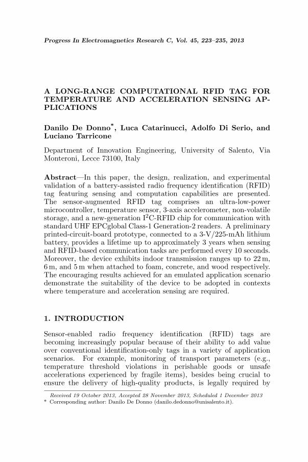
Figure 1. Prototype of the developed sensor-augmented RFID tag.
interface for communication with standard Gen2 readers. The sensor-augmented RFID tag operates in battery-assisted-passive (BAP) mode,i.e., it communicates with the reader via the zero-power backscatteringtechnique but derives power from an on-board battery. The deviceis fabricated using off-the-shelf low-cost discrete components on anFR4 substrate (see Fig. 1) and is equipped with microcontrollerunit (MCU), temperature sensor, 3-axis accelerometer, and a largeEEPROM for data logging. As discussed later in the paper, thesensor-augmented RFID tag exhibits appealing performance in termsof power consumption and maximum communication distance withthe reader, even when mounted on harsh, rugged surfaces. Moreover,in contrast to application-specific fixed-function IC products, ourapproach, based on a printed-circuit-board open-hardware design,offers flexibility to interface new sensors, actuators, modules, anddevices for further expanding the range of applications, e.g., towardsheterogeneous Wireless Sensor Networks (WSN) [7]. A real-worldexperiment illustrative of the capabilities provided by the sensor-augmented RFID tag is presented at the end of the paper: thedevice is used to monitor ambient temperature conditions and staticacceleration of a parcel in order to catch significant events (e.g.,displacements, abusive handling, temperature threshold violations,etc.) during a simulated shipment.
This paper is organized as follows. Architecture, components,and design of the sensor-augmented RFID tag are discussed inSection 2. A series of experiments aimed at assessing the deviceperformance are presented in Section 3 along with a potential use-casescenario concerning temperature and acceleration monitoring. Finally,conclusions are drawn in Section 4.
226 De Donno et al.
2. DESIGN AND IMPLEMENTATION
The design here proposed for the sensor-augmented RFID tag relieson a simple yet effective operating principle. A canonical UHF RFIDtag, composed of a dipole-like antenna and a Gen2 chip, makes up theradio front end. The main peculiarity of the adopted RFID chip is thecapability of its memory to be accessed via the wired I2C interface, inaddition to the standard Gen2 wireless interface. As a consequence,sensor data transferred over the I2C bus by means of an MCU aredirectly accessible to conventional RFID Gen2 readers.
The sensor-augmented RFID tag is powered by a 3-V/225-mAhCR2032 button-cell lithium battery connected to a TI TPS78330 3-Vlow-dropout (LDO) linear voltage regulator. Additional energy sourcesor energy-harvesting modules [8, 9] can be easily interfaced with thedevice by connecting them directly to the LDO regulator. The core ofthe system is an ultra-low-power 16-bit MSP430F5310 MCU which canrun up to 25 MHz with 3-V supply voltage and consumes approximately115µA/MHz. The supply current reduces to 1.9µA/MHz in sleepmode with real-time clock crystal, full RAM retention, and 5-µs wake-up time. The MCU provides also 32 kB of flash memory, 6 kB of SRAM,a 12-channel 10-bit 200-ksps Analog-to-Digital Converter (ADC), and47 GPIO. To further extend the storage capabilities of the device, anadditional 256-kB serial CMOS EEPROM is interfaced with the MCUvia the I2C bus.
The MCU is programmed with an energy-efficient firmwarerunning at 1MHz and implementing I2C read/write and ADC samplingroutines. The 10-bit ADC samples the integrated analog temperaturesensor consuming down to 9µA. Then, readings from an ADXL346accelerometer are taken via the I2C interface. The ADXL346 is anultra-low power (23-µA current consumption) 3-axis accelerometerwith 13-bit resolution measurements for each axis up to ±16 g.The sensor readings are wrapped in a 64-bit data chunk — 10-bittemperature, 13-bit acceleration for each of the three axes, and 15-bitread counter — which is written (via the I2C bus) into the password-protected user memory of the RFID Gen2 chip. Such an approachleaves the 96-bit EPC of the tag totally reserved for device/productidentification, thus enabling fully EPCglobal-compliant applications.
A compact dipole-like RFID antenna has been designed for theradio front end. The complex input impedance of the antenna hasbeen tuned to match that of an Impinj Monza X-2K RFID chip(Zchip = Rchip + jXchip = 20.83 − j181.39Ω) at 866.5 MHz, i.e., thecenter frequency of the European UHF RFID band. The Monza X-2K is an UHF RFID Gen2 IC with 2176 bits of password-protected
Progress In Electromagnetics Research C, Vol. 45, 2013 227
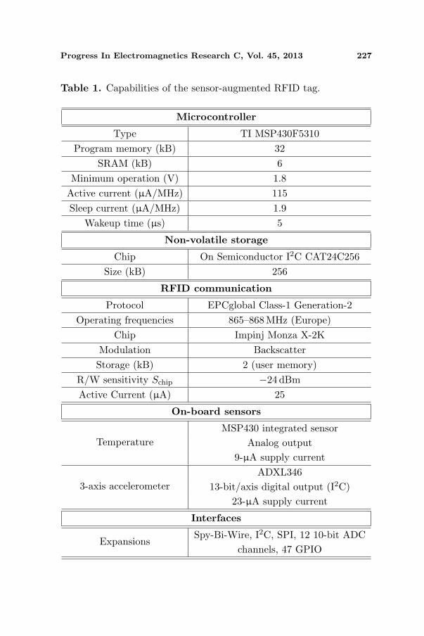
Table 1. Capabilities of the sensor-augmented RFID tag.
Microcontroller
Type TI MSP430F5310Program memory (kB) 32
SRAM (kB) 6Minimum operation (V) 1.8
Active current (µA/MHz) 115Sleep current (µA/MHz) 1.9
Wakeup time (µs) 5
Non-volatile storage
Chip On Semiconductor I2C CAT24C256Size (kB) 256
RFID communication
Protocol EPCglobal Class-1 Generation-2Operating frequencies 865–868MHz (Europe)
Chip Impinj Monza X-2KModulation BackscatterStorage (kB) 2 (user memory)
R/W sensitivity Schip −24 dBmActive Current (µA) 25
On-board sensors
TemperatureMSP430 integrated sensor
Analog output9-µA supply current
3-axis accelerometerADXL346
13-bit/axis digital output (I2C)23-µA supply current
Interfaces
ExpansionsSpy-Bi-Wire, I2C, SPI, 12 10-bit ADC
channels, 47 GPIO
228 De Donno et al.
non-volatile memory (NVM) and an I2C interface. As an I2C device,Monza X-2K operates as a standard EEPROM whose contents canalso be accessed wirelessly via the Gen2 protocol. The antenna designtakes cue from the commercial ALN-9660 RFID tag inlay which usesmeander lines to achieve a very compact form factor (7.5 × 1.7 cm2).Note that, depending on the application and the harshness of theenvironment, a directive patch antenna instead of an omnidirectiondipole could be used to achieve higher performance (e.g., a longer readrange) and platform tolerance [10–13].
A detailed overview of computation, sensing, storage, andcommunication capabilities of the sensor-augmented RFID tag is givenin Table 1.
3. PERFORMANCE EVALUATION
The prototype of sensor-augmented RFID tag shown in Fig. 1 has beenfabricated in our labs by using a photolithography process on FR4substrate and handy soldering off-the-shelf discrete components. TheRFID antenna has been patterned directly on the PCB. A small femaleheader and solder landings expose the Spy-Bi-Wire programminginterface, the I2C bus, and other MCU ports for future expansionsto external sensors and devices. Detailed simulations taking intoaccount the effect of the DC metal traces have been conducted inorder to maximize the performance and optimize the design of the finalprototype. The achieved results are presented and discussed below.
3.1. RFID Antenna
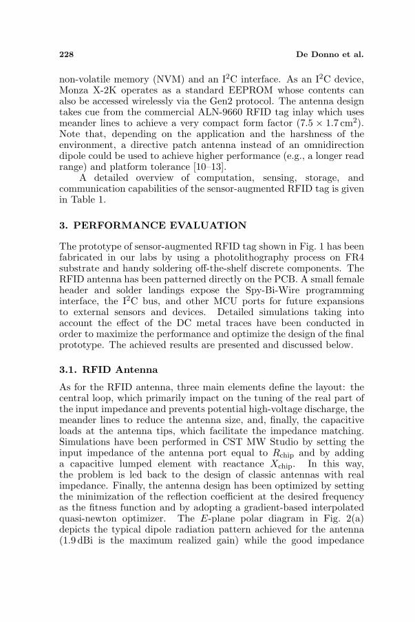
As for the RFID antenna, three main elements define the layout: thecentral loop, which primarily impact on the tuning of the real part ofthe input impedance and prevents potential high-voltage discharge, themeander lines to reduce the antenna size, and, finally, the capacitiveloads at the antenna tips, which facilitate the impedance matching.Simulations have been performed in CST MW Studio by setting theinput impedance of the antenna port equal to Rchip and by addinga capacitive lumped element with reactance Xchip. In this way,the problem is led back to the design of classic antennas with realimpedance. Finally, the antenna design has been optimized by settingthe minimization of the reflection coefficient at the desired frequencyas the fitness function and by adopting a gradient-based interpolatedquasi-newton optimizer. The E-plane polar diagram in Fig. 2(a)depicts the typical dipole radiation pattern achieved for the antenna(1.9 dBi is the maximum realized gain) while the good impedance
Progress In Electromagnetics Research C, Vol. 45, 2013 229
matching around the frequency of interest (−13 dB is the reflectioncoefficient magnitude at 866.5 MHz) is highlighted in Fig. 2(b).
(a) (b)
Figure 2. Simulated radiation pattern and reflection coefficient ofthe designed dipole-like RFID antenna. (a) E-plane polar radiationpattern. (b) Reflection coefficient.
3.2. Current Consumption and Lifetime
In order to evaluate the power consumption and, consequently,the lifetime of the the sensor-augmented RFID tag, the MCU wasprogrammed to perform temperature and acceleration sensing, enterthe sleep mode upon task completion, and be awakened periodically byan internal timer interrupt. A digital oscilloscope was used to track thevoltage drop across a 1-kΩ precision shunt resistor, specifically designedfor current-sensing applications, connected in series with the sensor-augmented RFID tag. Then, the DC current flowing through thedevice was calculated by the Ohm’s law. It was found that the MCUstartup and sleep phases consume Istartup = 500µA and Isleep = 3 µArespectively, while peaks of Iactive = 150µA occur during the activeperiods of the MCU performing temperature/acceleration sensing andRFID communication. The device lifetime L due to the available on-board power can be estimated by the following equation:
L =C · (Tactive + Tsleep)
Iactive · Tactive + Isleep · Tsleep(1)
where C is the battery capacity in Ampere per hour and Tactive
(Tsleep) is the duration of the active (sleep) period. Considering
230 De Donno et al.
Tactive = 400 ms as the measured time required by the device tocomplete sensing and communication tasks and C = 225 mAh asthe capacity of the on-board CR2032 lithium battery, a lifetime Lof approximately 3 years can be achieved when the sensor-augmentedRFID tag is configured to be awakened every Tsleep = 10 s.
3.3. Sensitivity and Read Range
The RFID front end of the sensor-augmented tag comprises a MonzaX-2K Gen2 chip and a dipole-like antenna. In order to correctlycharacterize the RFID performance, chip and antenna must be takeninto account jointly. Indeed, the former (Schip = −24 dBm for theMonza X-2K chip) determines the minimum RF power needed for thechip to reliably decode the reader commands while the latter plays acrucial role in terms of power transfer to the chip.
The comprehensive sensitivity of the sensor-augmented RFID tagwas measured in anechoic chamber by connecting a software-definedradio (SDR) equipment implementing the Gen2 protocol [14–16] to acircularly polarized antenna (gain Gtx = 5.5 dBi) placed at d = 1−mline-of-sight (LOS) distance from the device oriented in the maximum-gain direction. The minimum power Ptx,on required to communicatewith the tag attached to three different surfaces (specifically foam,wood, and concrete) was recorded in the 860–930 MHz frequency band.Then, the sensitivity Stag was calculated by the following equation(see [17] and [18] for its derivation) based on the free-space Friis’propagation model:
Stag = EIRPon
(λ
4πd
)2
ηplf (Watt) (2)
where EIRPon = Ptx,onGtx is the minimum equivalent isotropicallyradiated power (EIRP) required to communicate with the sensor-augmented RFID tag, λ the wavelength, and ηplf = 0.5 the polarizationloss factor due to the circularly polarized antenna of the SDRequipment.
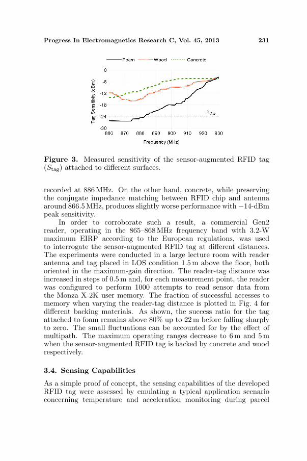
As shown in Fig. 3, the good impedance matching of the designedRFID antenna around 866.5 MHz (refer to Fig. 2(b)) makes the tagsensitivity Stag on foam almost identical to Schip in the EuropeanUHF RFID band. The approximate 2-dB difference can be accountedfor by the gain of the dipole-like RFID antenna. Moreover, therapid degradation of Stag when moving away from this frequencyband replicates precisely the trend of the antenna reflection coefficient.Attaching the tag to a wooden surface detunes the RFID antenna anddegrades the overall performance with −16 dBm of peak sensitivity
Progress In Electromagnetics Research C, Vol. 45, 2013 231
Figure 3. Measured sensitivity of the sensor-augmented RFID tag(Stag) attached to different surfaces.
recorded at 886 MHz. On the other hand, concrete, while preservingthe conjugate impedance matching between RFID chip and antennaaround 866.5 MHz, produces slightly worse performance with−14-dBmpeak sensitivity.
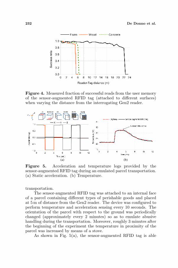
In order to corroborate such a result, a commercial Gen2reader, operating in the 865–868 MHz frequency band with 3.2-Wmaximum EIRP according to the European regulations, was usedto interrogate the sensor-augmented RFID tag at different distances.The experiments were conducted in a large lecture room with readerantenna and tag placed in LOS condition 1.5 m above the floor, bothoriented in the maximum-gain direction. The reader-tag distance wasincreased in steps of 0.5m and, for each measurement point, the readerwas configured to perform 1000 attempts to read sensor data fromthe Monza X-2K user memory. The fraction of successful accesses tomemory when varying the reader-tag distance is plotted in Fig. 4 fordifferent backing materials. As shown, the success ratio for the tagattached to foam remains above 80% up to 22m before falling sharplyto zero. The small fluctuations can be accounted for by the effect ofmultipath. The maximum operating ranges decrease to 6 m and 5mwhen the sensor-augmented RFID tag is backed by concrete and woodrespectively.
3.4. Sensing Capabilities
As a simple proof of concept, the sensing capabilities of the developedRFID tag were assessed by emulating a typical application scenarioconcerning temperature and acceleration monitoring during parcel
232 De Donno et al.
Figure 4. Measured fraction of successful reads from the user memoryof the sensor-augmented RFID tag (attached to different surfaces)when varying the distance from the interrogating Gen2 reader.
(a) (b)
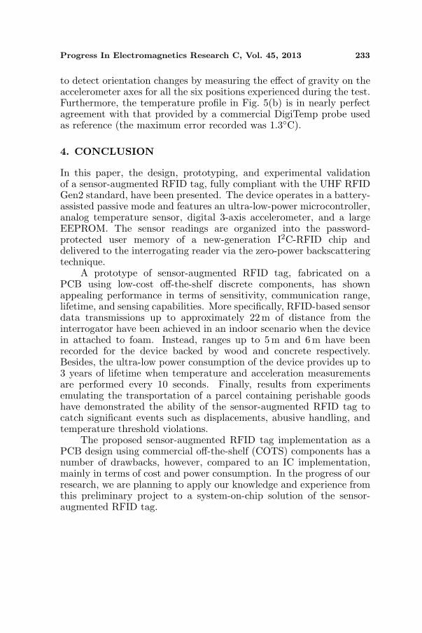
Figure 5. Acceleration and temperature logs provided by thesensor-augmented RFID tag during an emulated parcel transportation.(a) Static acceleration. (b) Temperature.
transportation.The sensor-augmented RFID tag was attached to an internal face
of a parcel containing different types of perishable goods and placedat 5m of distance from the Gen2 reader. The device was configured toperform temperature and acceleration sensing every 10 seconds. Theorientation of the parcel with respect to the ground was periodicallychanged (approximately every 2 minutes) so as to emulate abusivehandling during the transportation. Moreover, roughly 3 minutes afterthe beginning of the experiment the temperature in proximity of theparcel was increased by means of a stove.
As shown in Fig. 5(a), the sensor-augmented RFID tag is able
Progress In Electromagnetics Research C, Vol. 45, 2013 233
to detect orientation changes by measuring the effect of gravity on theaccelerometer axes for all the six positions experienced during the test.Furthermore, the temperature profile in Fig. 5(b) is in nearly perfectagreement with that provided by a commercial DigiTemp probe usedas reference (the maximum error recorded was 1.3C).
4. CONCLUSION
In this paper, the design, prototyping, and experimental validationof a sensor-augmented RFID tag, fully compliant with the UHF RFIDGen2 standard, have been presented. The device operates in a battery-assisted passive mode and features an ultra-low-power microcontroller,analog temperature sensor, digital 3-axis accelerometer, and a largeEEPROM. The sensor readings are organized into the password-protected user memory of a new-generation I2C-RFID chip anddelivered to the interrogating reader via the zero-power backscatteringtechnique.
A prototype of sensor-augmented RFID tag, fabricated on aPCB using low-cost off-the-shelf discrete components, has shownappealing performance in terms of sensitivity, communication range,lifetime, and sensing capabilities. More specifically, RFID-based sensordata transmissions up to approximately 22 m of distance from theinterrogator have been achieved in an indoor scenario when the devicein attached to foam. Instead, ranges up to 5 m and 6m have beenrecorded for the device backed by wood and concrete respectively.Besides, the ultra-low power consumption of the device provides up to3 years of lifetime when temperature and acceleration measurementsare performed every 10 seconds. Finally, results from experimentsemulating the transportation of a parcel containing perishable goodshave demonstrated the ability of the sensor-augmented RFID tag tocatch significant events such as displacements, abusive handling, andtemperature threshold violations.
The proposed sensor-augmented RFID tag implementation as aPCB design using commercial off-the-shelf (COTS) components has anumber of drawbacks, however, compared to an IC implementation,mainly in terms of cost and power consumption. In the progress of ourresearch, we are planning to apply our knowledge and experience fromthis preliminary project to a system-on-chip solution of the sensor-augmented RFID tag.
234 De Donno et al.
REFERENCES
1. Mainetti, L., L. Patrono, and R. Vergallo, “IDA-pay: Asecure and efficient micro-payment system based on peer-to-peer NFC technology for android mobile devices,” Journal ofCommunications Software and Systems, Vol. 8, No. 4, 117–125,2012.
2. Guido, A. L., L. Mainetti, and L. Patrono, “Evaluating potentialbenefits of the use of RFID, EPCglobal, and ebXML in thepharmaceutical supply chain,” International Journal of HealthcareTechnology and Management, Vol. 13, No. 4, 198–222, 2012.
3. Sample, A. P., D. J. Yeager, P. S. Powledge, A. V. Mamishev, andJ. R. Smith, “Design of an RFID-based battery-free programmablesensing platform,” IEEE Transactions on Instrumentation andMeasurement, Vol. 57, No. 11, 2608–2615, Nov. 2008.
4. De Donno, D., L. Catarinucci, and L. Tarricone, “Enablingself-powered autonomous wireless sensors with new-generationI2C-RFID chips,” 2013 IEEE MTT-S International MicrowaveSymposium Digest, 1–4, Jun. 2013.
5. Unander, T., J. Siden, and H. E. Nilsson, “Designing of RFID-based sensor solution for packaging surveillance applications,”IEEE Sensors Journal, Vol. 11, No. 11, 3009–3018, Nov. 2011.
6. Li, T. H., A. Borisenko, and M. Bolic, “Open platform semi-passive RFID tag,” Ad-hoc, Mobile, and Wireless Networks,Lecture Notes in Computer Sciences (LNCS), Vol. 7363, 249–259,2012.
7. Capone, A., M. Cesana, D. De Donno, and I. Filippini, “Optimalplacement of multiple interconnected gateways in heterogeneouswireless sensor networks,” NETWORKING 2009, Lecture Notesin Computer Science (LNCS), Vol. 5550, 442–455, 2009.
8. De Donno, D., L. Catarinucci, and L. Tarricone, “An UHF RFIDenergy-harvesting system enhanced by a DC-DC charge pump insilicon-on-insulator technology,” IEEE Microwave and WirelessComponents Letters, Vol. 23, No. 6, 315–317, Jun. 2013.
9. Monti, G., F. Congedo, D. De Donno, and L. Tarricone,“Monopole-based rectenna for microwave energy harvesting ofUHF RFID systems,” Progress In Electromagnetics Research C,Vol. 31, 109–121, 2012.
10. Catarinucci, L., S. Tedesco, D. De Donno, and L. Tarricone,“Platform-robust passive UHF RFID tags: A case-study inrobotics,” Progress In Electromagnetics Research C, Vol. 30, 27–39, 2012.
Progress In Electromagnetics Research C, Vol. 45, 2013 235
11. Lee, H., S. Kim, D. De Donno, and M. M. Tentzeris, “A novel‘Universal’ inkjet-printed EBG-backed flexible RFID for ruggedon-body and metal mounted applications,” 2012 IEEE MTT-SInternational Microwave Symposium Digest, 1–3, Montreal, QC,Canada, 2012.
12. Liu, Y., K.-M. Luk, and H.-C. Yin, “A RFID tag metal antenna ona compact HIS substrate,” Progress In Electromagnetics ResearchLetters, Vol. 18, 51–59, 2010.
13. Paredes, F., G. Zamora, S. Zuffanelli, F. J. Herraiz-Martinez, F.Martin, and J. Bonache, “Free-space and on-metal dual-band tagfor UHF-RFID applications in Europe and USA,” Progress InElectromagnetics Research, Vol. 141, 577–590, 2013.
14. De Donno, D., F. Ricciato, and L. Tarricone, “Listening totags: Uplink RFID measurements with an open-source software-defined radio tool,” IEEE Transactions on Instrumentation andMeasurement, Vol. 62, No. 1, 109–118, Jan. 2013.
15. De Donno, D., L. Catarinucci, L. Tarricone, V. Lakafosis,and M. M. Tentzeris, “Performance enhancement of the RFIDEPC Gen2 protocol by exploiting collision recovery,” Progress InElectromagnetics Research B, Vol. 43, 53–72, 2012.
16. De Donno, D., V. Lakafosis, L. Tarricone, and M. M. Tentzeris,“Increasing performance of SDR-based collision-free RFID sys-tems,” 2012 IEEE MTT-S International Microwave SymposiumDigest, 1–3, Montreal, QC, Canada, 2012.
17. Catarinucci, L., D. De Donno, M. Guadalupi, F. Ricciato,and L. Tarricone, “Performance analysis of passive UHF RFIDtags with GNU-radio,” 2011 IEEE International Symposium onAntennas and Propagation (APSURSI), 541–544, 2011.
18. De Donno, D., L. Catarinucci, R. Colella, F. Ricciato, andL. Tarricone, “Differential RCS and sensitivity calculation of rfidtags with software-defined radio,” 2012 IEEE Radio and WirelessSymposium (RWS 2012), 9–12, Santa Clara, CA, USA, 2012.