A local PUFEM modeling of stress singularity in sliding ...
26
This article appeared in a journal published by Elsevier. The attached copy is furnished to the author for internal non-commercial research and education use, including for instruction at the authors institution and sharing with colleagues. Other uses, including reproduction and distribution, or selling or licensing copies, or posting to personal, institutional or third party websites are prohibited. In most cases authors are permitted to post their version of the article (e.g. in Word or Tex form) to their personal website or institutional repository. Authors requiring further information regarding Elsevier’s archiving and manuscript policies are encouraged to visit: http://www.elsevier.com/authorsrights
Transcript of A local PUFEM modeling of stress singularity in sliding ...

This article appeared in a journal published by Elsevier. The attachedcopy is furnished to the author for internal non-commercial researchand education use, including for instruction at the authors institution
and sharing with colleagues.
Other uses, including reproduction and distribution, or selling orlicensing copies, or posting to personal, institutional or third party
websites are prohibited.
In most cases authors are permitted to post their version of thearticle (e.g. in Word or Tex form) to their personal website orinstitutional repository. Authors requiring further information
regarding Elsevier’s archiving and manuscript policies areencouraged to visit:
http://www.elsevier.com/authorsrights

Author's personal copy
A local PUFEM modeling of stress singularity in sliding contact with minimal enrichment for direct evaluation of generalized stress intensity factors
S.H. Ebrahimi, S. Mohammadi ⇑, I. Mahmoudzadeh Kani School of Civil Engineering, University of Tehran, Tehran, Iran
a r t i c l e i n f o
Article history:Received 30 June 2012 Received in revised form 19 January 2013 Accepted 31 March 2013 Available online 8 April 2013
Keywords:Stress singularity Sliding friction Minimal enrichment PUFEM
a b s t r a c t
The order of stress singularity around sharp corners is studied by solving the characteristic equation numerically. The corresponding displacement and stress fields around the sharp corners, which accurat ely satisfy the compatibility of deformation and stress states on the two sides of the slave corner, are derived for various contact configurations. The domi nant mode of infinite asymptotic stress field for contact problems is then implemented with minimum enrichments (2 functions for each enriched node), for the first time, wit hin the framew ork of partition of unity finite element. An increased rate of convergence isachieved and the generalized stress intensity factor can be obtained directly from the addi- tional unknowns. Numerical examples demonstrate the superior accuracy of the present approach to capture the sliding contact stress singularities near sharp corners.
� 2013 Elsevier Ltd. All rights reserved.
1. Introductio n
The study of stresses around the corner of composite wedges in contact is important in many industria l and research practices [1]. Among them, various indentation tests are commonly used to estimate the mechanical properties of thin films,surface coated specimen and bulk materials. These mechanical properties comprise elastic modulus, Poisson’s ratio, yield strength, stress hardening, power-low and/or other plastic, viscous and dynamic constituti ve parameters. On the other hand,indentation process is present as a component of many manufactur ing procedures which leads to conversion of a material from a primary form into more valuable productions through the use of mechanical processes such as rolling, forging, extru- sion, coining, drawing and molding.
In the structural engineering field welded joints which comprise in-plane or out of plane indentation of sharp edges on anadhesive interface with a plate, may experience stress singularities which are a major source for potential failures. Despite the fact that indentati on of sharp corners are known to cause problems and therefore are usually avoided in engineering de- sign, there are some situations in industry where contact or impact of non-conformi ng interfaces are inevitable and thus anaccurate estimation of the intensity of the local stress field is valuable for appropriate design, fabrication and maintenanc e ofindustrial instruments . Complete sliding contact of a punch in screw press cycles, ring rolling and cutting in metal forming processes are among such practical applications . Pertinent singulari ties are associated with different configuration of contact of dissimilar materials with different interfacia l boundary conditions. In addition, fretting fatigue and crack nucleation and growth in the vicinity of the contact zone due to alternating high stress gradient may also be of interest.
0013-7944/$ - see front matter � 2013 Elsevier Ltd. All rights reserved.http://dx.doi.org/10.1016/j.engfracmech.2013.03.032
⇑ Corresponding author. Address: High Performance Computing Lab, School of Civil Engineering, University of Tehran, Iran. Tel.: +98 21 6111 2258; fax:+98 21 6640 3808.
E-mail address: [email protected] (S. Mohammadi).
Engineering Fracture Mechanics 105 (2013) 16–40
Contents lists available at SciVer se ScienceD irect
Engin eering Fractu re Mec hanics
journal homepage: www.elsevier .com/locate /engfracmech

Author's personal copy
Owing to the fact that the form of stress field near the singular points is independen t of the far-field boundary conditions,the method of complex variables and semi-anal ytical methods are capable of determining the complete nature of the local high gradient or singular solution. Among these approach es are the complex function representat ion and the Mellin trans- form technique by Sternberg and Koiter [2], originally proposed for local mode expansion on the interface of composite bodies in linear elasticity . A semi-analytica l approach that has been frequently used in the literature is the eigenfunctio nexpansion method. The approach gives the opportunity to capture the self-simi lar higher order displacemen t fields near the point of transition of slip-stick boundary condition s in frictional contact interface or singular fields near the edge inden- tation or penetration of a sliding cone (i.e. a pile tip penetrating into the soil). The method indicates noticeable advantages inmodeling a number of important engineering problems : interfacial contact along crack faces, missiles penetrating dissimilar deformable media and frictional conformi ng contact problems [3]. Brahtz appears to be the first to report the existence of
Nomencla ture
a vector of additiona l degrees of freedom aja additiona l degrees of freedom associated to the enrichment function Fa(x) and compact support of Ni(x)A, B, C, D, A0, B0, C0, D0 paramet ers of the eigenfunc tion expansion Aj, Bj, Cj, Dj parameters of the eigenfunc tion for the jth wedge A�i ;B
�i ;C
�i ;D
�i auxiliary asymptotic field parameters
B_
ðXÞ strain–displacement matrix for the enriched degrees of freedom d dimension of the block DTOL user defined tolerance for error control paramet erF; F
_
ðk; hÞ radial term of the Airy stress function Fext
i external load vector compon ent at the ith incremen tF_
xðxÞ; F
_
yðxÞ enrich ment function in local x and y coordinat es of the singula r point
Fa(x) ath enrichm ent function g1(h), g2(h) first and second terms of the angular modes of the eigenfunctio n expansion gij(h) angular term of the eigenfunc tion expansion for the jth component of displaceme nt vector Gjðh; kÞ angular term of the Airy stress function for the jth wedge ki coefficients of the ith term of eigenfunc tion expansion K(Ui) total stiffness matrix due to updated configuration at the end of the ith increment Ui
KI, KII GSIF for the first and second terms of the eigenfunc tion expansion KI;KII first and second terms of the angular modes of the eigenfunc tion expansion for double root solutions KGSIF generalized stress intensity factor Ni(x) finite element interpo lation function r, h radius and angle re radius of enrichment domain rq radius of the contou r integral path R error control parameter ti; t�i primary and auxiliary traction vector component sU asymptotic displaceme nt fielduh(x) finite element displaceme nt approximat ion ui displaceme nt vector compon ents u�ij auxiliary displacemen t vector D, Dr, Di eigen-equat ion and its real and imaginary parts DTi load step size for the ith increment DU1, DU2 first and second orders of displaceme nt increment lf coefficient of friction lj shear modulus for the jth wedge j Kolosov’s constant k; k� singularity power, eigenvalue associat ed to the auxiliary fieldrij primary stress tensor n, g real and imaginary parts of the singula rity power e_ðXÞ strain contribution of enrichment
/, /I, /II Airy stress function, first and second terms of eigenfunc tion expansion /ki
log logarithmic Airy stress function for k ¼ ki
C = Ce [ C1 [ Cm [ Cs contour integral path r�ij auxiliary stress tensor X� contour integral domain Uj Airy stress function for the jth wedge R asymptotic stress field
S.H. Ebrahimi et al. / Engineering Fracture Mechanics 105 (2013) 16–40 17

Author's personal copy
contact corner singularities in 1933 [4]. Williams carried out the first systemati c study of singularities near corners with free–free, fixed–fixed and free–fixed boundary condition s [5]. The work of Williams was further extended by Karal and Karp [6], Kalandiia [7], England [8] and Vasilopoul os [9–11], among the others. Sternberg and Koiter studied the multiple roots inthe Williams eigenfun ction expansion [2]. Later, Dempsey and Sinclair obtained the logarithmic non-separable solution for singular wedge problems from the derivative of the Williams solution with respect to the singularity power for the first time [12]. Joseph and Zhang [13] discussed the multiple root solutions and singular stress states that were not variable-s eparable,following the method of Frobenius. Dini et al. dealt with inhomogene ous boundary condition s such as ‘‘patching in’’ a solu- tion for the effect of the rounding of the sharp corner (e.g. boundary condition o uh/o r = cr, at free edges of a wedge) [14].
Several studies have concentrated on different material behavior (e.g. anisotropic, strain hardening or a variety of multi- material elastic composites) and the possibility of a logarithmi c singularity. The asymptotic singular fields for many adhesive joint geometries are not available due to the complexity of the analytica l formulat ions. The length of resulting expressions for the determinant form eigenfunctio n equation, which gives the singularity or high intensity power, increases very fast when the number of involved materials is increased or there is a diversity in the boundary condition s on different interfaces.For instance, in bi-materials it is about one page expression; for three materials the expression of the determinan t reaches toabout 15 pages and for four materials it may even exhaust the capability of many computer s [15]; therefore, the compact form of the characteristic equations, if it can be found, is very useful for computation and analysis. Particula rly in recent years, the use of these eigen-function s to better reproduce the local character of the solution around singular points has be- come important in computational mechanics. Once the nature of the stress singularity is determined analytically , the cor- responding asymptotic displacemen t fields may be used as shape functions to enrich the solution field in the vicinity ofthe contact corner by PUFEM or XFEM frameworks [16].
Contact mechanics literature incorporates numerous algorithms that deal with interaction of different fluids and/or struc- tures. A three-dim ensional extended EFG method coupled with FEM was utilized for modeling cohesive crack growth in rein- forced concrete structures [17]. Bordas et al. [18] introduce d a three-dimensio nal extrinsically enriched EFG for treatment ofevolving multiple cracks in nonlinear solids including large deformations without near-tip enrichment. They proposed the construction of a Lagrange multiplier field in lieu of near-tip enrichment or influence domain adjustment to close the cracks along their fronts. A Meshfree thin shell model based on the Kirchhoff–Love theory was also adopted for nonlinear analysis ofarbitrary evolving cracks [19]. Another method for treating crack growth in 3D particle methods by introducing the failure direction at individua l particles based on a mixed Lagrangian–Eulerian kernel formulat ion was proposed by Rabczuk and Belytschko [20,21]. A local partition of unity enriched EFG method to simulate crack nucleation, propagat ion and joining cracks in nonlinear three dimensional solids was presented in [22], while Rabczuk et al. [23] proposed ‘‘Immersed Particle method’’ as a master–slave Lagrangian meshfree contact algorithm for dealing fluid–structure interactions. The recent work of Menk and Bordas [24] also determined numerically the order of singularity for some asymptotic problems of strain sin- gularity such as junction points including a polycrystall ine structure based on the approach develope d by Li et al. [25].Though well applicable for asymptotic problems especiall y in anisotropi c materials, the proposed algorithm was merely an approximat ion of the singular field, with dependence on the angular discretiza tion density around the singular point.
The state of stress singulari ty around bonded and sliding punch corners has been studied in both qualitative and quan- titative analysis categories. The outline of the stress field near the corner vertex has been examined in a qualitative way via isochromatic patterns in some photo-elast icity experiments, which approved the existence of stress singularity for both lubricated and dry interfaces [26]. Very good agreements have been reported between the experimental and analytica l solu-
Fig. 1. A typical contour of asymptotic shear stress rrh obtained by the present study in comparison with an isochromatic view (upper left) in the vicinity ofa sharp corner for a frictionless lubricated interface angle (/ >¼ 77:5�) of identical materials at which singularity starts to appear [26].
18 S.H. Ebrahimi et al. / Engineering Fracture Mechanics 105 (2013) 16–40

Author's personal copy
tions on the shape of eigenfunction and the results of asymptotic analysis [27,28], as depicted typically in Fig. 1 in the vicin- ity of a sharp corner for a sliding steel punch on a steel half-plane.
Analytical investigatio n on the distribut ion of elastic fields near the end of the contact zone for the bonded punch corner is due to Williams [5], while the characterist ic equation for sticking punch was solved by Gdoutos and Theocaris [29] andComninou [30]. The obtained characteri stic roots, i.e. the singularity power, form the eigen-funct ions which satisfy the boundary condition s and reproduce the singular stress field [16,26].
The numerical solution of eigenvalue problem for general interface boundary conditions in linear elasticity was originally proposed by Lee and Barber [27]. However, since the method assigns only one angle to each contact interface, then for exam- ple the problem of antisymmetric sliding around a corner cannot be studied. Asymptotic fields near the singular points intwo dimensional orthotropic elastic media and the explicit form of the eigenequati on of bonded orthotropic edge with anarbitrary wedge angle to an isotropic half-plane have been addresse d in Wu and Liu [31]. Solving the characteristic equation numerically , gives the opportunity to capture singular stress fields in contact of orthotropic composite targets with the pres- ent approach.
Developing new enrichment functions to capture a local behavior of the solution has been frequently used as an efficientway of simulatio n for fracture problems [32–38]. In this paper, however, the singulari ty due to various frictional contact problems is considered and the correspond ing enrichment functions are derived.
Enrichme nt functions have already been proposed in the framework of the asymptotic eigenfunction expansion in the literature for slipping and sticking punch indentation and bonded sides corner penetrati on in dissimilar materials [39]. Inthe next section, node-to-seg ment (NTS) slide line formulation will be enriched to reproduce the superior modes of stress singularity. The strength of singularity and the relative asymptoti c parameters are determined in terms of the specified mas- ter and slave material elastic modules, corner angles and coefficients of friction. In contrast to Giner et al. [16], who studied the same case of sliding punch, the number of additional degrees of freedom is reduced as a result of combinin g the basic asymptotic modes in order to satisfy the characteri stic equation by determining the field parameters in the pre-processi ngphase. The enrichment functions derived from the biharmon ic equation of elasticity are the solution to several asymptotic problems with different boundary conditions, but with the same eigen-value. Therefore, the interface equilibriu m is required to be upheld with sufficient accuracy in order to provide accurate results. In order to determine the generalized stress inten- sity factor (GSIF) in contact problems, the alternative approach of the contour integral formulation may also be adopted. Anon-singula r mode of the eigen-equat ion produces the auxiliary mode which eliminates the line integral on free boundaries of the closed contour around the vertex point. The normal and tangential contact constraints are enforced by the penalty method. Based on the current contact state of the slave corner node, the sticking or sliding mode of enrichment is adopted.The projection point of the node on the master surface is determined in each increment and associate d master and slave ele- ments are enriched topologically or geometrical ly [16]. The master interface is smoothed very close to the discretized inter- face by the Bezier polynomials, which increases the stability of the penalty method in large sliding frictional contact problems [40]. Bouncing from free to slip condition is prevented by conventional contact mechanics algorithms and the starting contact condition remains stick [40]. Since the penalty stiffness contribution significantly changes the conditionin gof the global stiffness matrix, in order to prevent possible jumps from a slip state to free state of the slave nodes, especially ata corner node (which its location describes the origin of high gradient stress field), an automatic sub-increment ation scheme,which divides the load increment into substeps that satisfy an error control criterion, is applied, as proposed by Sheng and Sloan [41] and Sheng et al. [42].
2. Asymptotic expansion in 2D linear elasticity
The asymptotic expansion method, pioneered by Wieghardt [28] and followed by Williams [5] who extended the ap- proach to the analysis of stress singulari ty around the re-entrant corners in tensile plates and other singular wedge prob- lems, expresses the self-similar (separated-variable form) solution space around a vertex point of a composite wedge inthe form of u ¼ rkf ðhÞ, where r is the radius from the vertex point, k is the singularity order and f(h) denotes the angular dis- tribution of the mode shape. These series of Williams-ty pe solutions should satisfy the biharmon ic equation r4Uj = 0 for the jth wedge of the composite medium around a vertex. U is the Airy stress function and has the following general form for the wedge j [3]:
Uj ¼ rkþ1½Aj Bj Cj Dj �½F_
� ð1Þ
The corresponding stress and displacement fields can be written as,
½R� ¼ krk�1
�Ajðk� 3Þ �Bjðk� 3Þ �Cjðkþ 1Þ �Djðkþ 1ÞAjðkþ 1Þ Bjðkþ 1Þ Cjðkþ 1Þ Djðkþ 1ÞBjðk� 1Þ �Ajðk� 1Þ Djðkþ 1Þ �Cjðkþ 1Þ
264
375½F_� ð2Þ
½U� ¼ 12lj
rk Ajðjj � kÞ Bjðjj � kÞ �Cjðkþ 1Þ �Djðkþ 1ÞBjðjj þ kÞ �Ajðjj þ kÞ Djðkþ 1Þ �Cjðkþ 1Þ
� �½F_
� ð3Þ
S.H. Ebrahimi et al. / Engineering Fracture Mechanics 105 (2013) 16–40 19

Author's personal copy
F_
ðk; hÞ ¼ ½ sinðk� 1Þh cosðk� 1Þh sinðkþ 1Þh cosðkþ 1Þh �T ð4Þ
where R ¼ ½rrr rhh rrh �T and U ¼ ½ur uh �T are the stress and displacemen t vectors in polar coordinate system, respec- tively; the arrays of ½Aj Bj Cj Dj � are arbitrary constants and lj, jj are shear modulus and Kolosov’s constant, respec- tively. Substituti on of these equations into the appropriate homogeneous interface boundary conditions will create four homogeneous linear constraints for wedge interfaces and two traction-fre e constraints for free boundaries (if exist). As a re- sult, there exist 4n equations for 4n unknowns {Aj, Bj, Cj, Dj}j=1,n of n wedges. The resulting algebraic eigen-equation (i.e. the characterist ic equation) has several non-trivial solutions for the eigen-val ues k and the correspondi ng eigen-funct ions in aseparated variable form of fi(r)gij(h) (the ith eigen-funct ion for the jth wedge). They are obtained by setting the determinan tof the coefficients of the algebraic equation equal to zero [16]. The characterist ic equation is a function of k, the elastic con- stants such as lj, jj and the interface constants such as the Coulomb’s coefficient of friction for sliding/slipp ing boundaries.The general solution in the immediate vicinity of the vertex can be written in the form of eigenfun ction expansion
uj ¼X1i¼0
kirki gijðhÞ:
The solution associated with the smallest real part produces the highest deformat ion gradients (order of singulari ty). Fur- thermore, if this dominan t solution k0 satisfies Reðk0Þ < 1, a singular stress field is produced. However, solutions with Reðk0Þ < 0 are not feasible since they lead to an infinite displacement field. Thus, only solutions which meet 0 < Reðk0Þ < 1 are of practical interest [3].
To obtain the characteristic equation, for example for indentation of a sticking deformable punch into a semi-infinite elas- tic medium, the stick boundary condition is satisfied at h = 0 and the traction-free boundary condition is considered at h = /and h = �180 (Fig. 2).
The characteristic equation is treated via the standard Newton’s method. The order of the stress singularity versus the corner angle / is depicted in Fig. 3. In this figure, the Young’s modulus and Poisson’s ratio of steel and concrete are Esteel ¼ 200 GPa;msteel ¼ 0:30 and Econc ¼ 20 GPa;mconc ¼ 0:25:
As shown in Fig. 2, a couple of singular eigen-mode s are probable to be reproduced for intermediate punch angles /. The order of singularity is k ¼ 1 (non-singular) for / = 0 and k ¼ 0:5 for / = 180 irrespective of the material dissimilarity. The re- sults of analytical solution shows that for 0 < / < 180, the solution curve has two branches for the real part of singularity order. Two threshold angles (key angles) may be distingui shed for every material compositi on of slave and master media (see Fig. 3). The first key angle at A introduces the entrance of the second singular mode and the second key angle represents the point in which two eigenvalues approach to each other. Before the first key angle, the sticking punch configuration has only one singular mode and after the second key point at B (/ = 90 for steel/concr ete contact pair), the two eigenvalues are complex conjugates of each other. For similar materials, such as the steel/steel in Fig. 3, this second key angle occurs at 180 �
with the well-known square root singularity (i.e.k1 ¼ k2 ¼ 0:5).Having obtained the eigenvalue k; the parameters of the mode-shapes of the asymptotic expansion around the vertex
point {Aj, Bj, Cj, Dj}j=1,n are derived by the conventional Gauss reduction and back-substitut ion processes on the characterist icequation. The following functions are then derived for computing the analytical displacemen t field in the Cartesian coordinates ,
½u�i ¼ ½d�ij½F�jði ¼ x; y; j ¼ 1;4Þ ð5Þ
Fig. 2. Configuration of a complete sliding contact.
20 S.H. Ebrahimi et al. / Engineering Fracture Mechanics 105 (2013) 16–40

Author's personal copy
½F� ¼ rk½ sinðk� 2Þh sin kh cosðk� 2Þh cos kh �T ð6Þ
½d� ¼ KGSIF
l�kD jD� ðkþ 1ÞC �kB jB� ðkþ 1ÞAkB jBþ ðkþ 1ÞA �kD �jD� ðkþ 1ÞC
� �ð7Þ
where ui is the displacemen t field in the local coordinate system, l is the shear modulus of the wedge and KGSIF is the gen- eralized stress intensity factor. Eq. (5) will be used to define a consistent enrichment function to be embedded within the PUFEM.
3. Sliding punch corner indentation
Gdoutos and Theocaris [29] and Comninou [30] have derived the eigen-equation for a complete sliding punch on a dis- similar plane surface, as described in Fig. 2,
Dðk; /;a;b;lÞ ¼ 8ð1þ kÞ sin kp� ð1þ aÞ cos kpðsin2 k/� k2 sin2 /Þ þ 12ð1� aÞ sin kpðsin 2k/þ k sin 2/Þ
�
þl sin kp ð1� aÞkð1þ kÞ sin2 /� 2bðsin2 k/� k2 sin2 /Þh ii
¼ 0 ð8Þ
where / is the wedge angle and a ¼ ðl2=l1Þðj1þ1Þ�ðj2þ1Þðl2=l1Þðj1þ1Þþðj2þ1Þ ; b ¼
ðl2=l1Þðj1�1Þ�ðj2�1Þðl2=l1Þðj1þ1Þþðj2þ1Þ are the Dundurs parameters, lf is the coefficient of
friction and j = 3 � 4m for plane strain problems . The characteri stic Eq. (8) has been constructed from the asymptotic expan- sion of the following equations:
rð1Þrh þ lf rð1Þhh ¼ 0; rð1Þrh ¼ rð2Þrh ; rð1Þhh ¼ rð2Þhh ; uð1Þh ¼ uð2Þh ath ¼ 0 ð9Þ
rð1Þrh ¼ rð1Þhh ¼ 0 at h ¼ /;rð2Þrh ¼ rð2Þhh ¼ 0 at h ¼ �p ð10Þ
Eq. (8) may be solved numerica lly by using a mathematical software such as Maple, Mathematic a or Matlab which support symbolic equation manipulati ons or parametric solution. The result of the rather tedious symbolic calculations on the char- acteristic equation will be the real and imaginary parts of the characterist ic determinan t and their parametric derivatives with respect to real and imaginary parts of the eigenvalue k: Here, however , the Newton’s iterative method is adopted tosolve for the dominant k,
k ¼ eþ ig ð11Þ
and the characterist ic equation , typically written in terms of DðkÞ, is decomposed into its real and imaginary parts,
DðkÞ ¼ Drðe;gÞ þ iDiðe;gÞ ¼ 0 ð12Þ
Then, two sequential iterations for e and g are to be performed to converge to exact values within the predefined error tol- erance and the maximum number of iteration s,
eiþ1 ¼ ei � dei; dei ¼ �
Dr @Dr=@gDi @Di=@g
��������
@Dr=@e @Dr=@g@Di=@e @Di=@e
��������; giþ1 ¼ gi � dgi; dgi ¼ �
@Dr=@e Dr
@Di=@e Dr
��������
@Dr=@e @Dr=@g@Di=@e @Di=@e
��������
ð13Þ
Fig. 3. Order of stress singularity in terms of the punch angle for a sticking edge indentation problem. Left: Steel/Steel and Right: Steel/Concrete.
S.H. Ebrahimi et al. / Engineering Fracture Mechanics 105 (2013) 16–40 21

Author's personal copy
The components @Dk@klðk; l ¼ 1;2Þ are determined explicitly in terms of e and g. Unnecess ary parametri c calculations can be
avoided, knowing that: o Dr/o g = �o Di/o e; o Di/o g = o Dr/o e.Having found the eigenvalue and substituted it into the original matrix form of the eigen equation matrix, the diagonal
form of the equation , which has a zero in the last diagonal component, is derived using the conventional Gauss elimination process. Setting D = 1 (the last array of the eigenvector), the back-substitut ion process will extract the other arrays of the eigen-vecto r.
The solution of the eigen-equation for plane strain sliding of a steel punch on different substrates is shown in Fig. 4 whichdemonstrat es the trend of variation of the singulari ty power with respect to the vertex angle for various friction coefficients.The elasticity parameters for steel are Es ¼ 200 GPa;ms ¼ 0:3.
The order of stress singularity at the vertex depends on the direction in which the wedge slips with respect to the half space. In Fig. 4, positive coefficients of friction indicate sliding towards the vertex point (leading corner) and sliding away from the corner (trailing corner) produces lower singularity order. Such a regime governs stiffer slave and softer substrates only for acute angles. For angles greater than 90�, the trend reverses and as shown in Fig. 4, for a right angle corner of a steel specimen sliding on the substrate 3, the order of singulari ty is independent of the coefficient of friction. The corner angle atwhich the singularity power becomes independen t of the coefficient of friction varies for different punch/substrate stiffness ratios. For example, for a substrate of elastic parameters Ec ¼ 10 GPa;mr ¼ 0:25 (substrate 4), the singularity power for steel corner of 69:3� becomes independent of the coefficient of friction and is equal to k ¼ 0:5841; while for the substrate 2 with parameters Ec ¼ 30 GPa;mr ¼ 0:25, such a friction independent punch angle is 102 :26� with the correspond ing order of sin- gularity k ¼ 0:5411:
The variation of singularity power with respect to the coefficient of friction and sliding direction for 60�, 90� and 120 �
angles is depicted in Fig. 5. Again, negative friction coefficient corresponds to the sliding away from the corner point. The order of stress singulari ty increases by the increase of the coefficient of friction for relatively stiff punch with corner angles lower than 90�. For obtuse angles the trend is reversed with a mild rate. The variation of the order of singularity with respect
Fig. 4. Singularity power of a sliding steel punch corner versus corner angle. Upper left: Steel substrate 1 upper right: Substrate 2, Ec = 30 GPa, mc = 0.25.Lower left: Substrate 3, Ec = 20 GPa, mc = 0.25. Lower right: Substrate 4, Ec = 10 GPa, mc = 0.25.
22 S.H. Ebrahimi et al. / Engineering Fracture Mechanics 105 (2013) 16–40

Author's personal copy
to the relative elastic paramete rs is described in Fig. 6. It can be concluded from the results that for all trailing corners and the leading corner with relatively low friction coefficients, the order of singularity reduces for indenting low stiffness wedges. Similar conclusions were reported by Dundurs and Lee [43]. Dundurs and Lee [24,25] have also stated that the char- acteristic equation has just one real root [43]. The present solution of the roots of Dðk; /;a; b;lÞ (Eq. (8)), confirms that there is at most one real root in the interval 0 < k 6 1 [44,45].
Logarithm ic singulari ties accommodate the region between no singularity and power singularities (Williams-type singu- larities) at transition threshold k ¼ 1, where the singulari ty vanishes for k > 1, while k < 1 cases represent an exponential singularity. As discussed by Dundurs and Lee [43], a logarithmic solution stems from the double roots of the basic charac- teristic equation of the biharmonic equation. Supposing the separated variable exponential form of the Airy stress function as / ¼ Qeðkþ1Þ ln rgðhÞ, the solution for angular function g(h) leads to g(h) = exh where x is the solution of the following char- acteristic equation,
x4 þ 2ðk2 þ 1Þx2 þ ðk2 � 1Þ2 ¼ 0 ð14Þ
The solutions of (14) are explicitly derived as x ¼ �iðk� 1Þ. Existence of the identical solutions xI = xII, which occurs when k 2 f�1;0;1g, implies that the derivative of the angular mode with respect to eigenvalue, @gðx;hÞ
@x , to be the other conjugat e pair according to the method of Frobenius for multiple roots of the characterist ic equation. In a similar manner for the radial part of the Airy stress function f ðkÞ ¼ rk, when the eigenvalues corresponding to conjugate eigenfun ctions come close to each other on limit (kI ¼ kII), the mixed mode case of double roots incorporate s a logarithmic partner as @
@k f ðkÞ ¼ rk ln r: Dempseyand Sinclair were the first to obtain the logarithmic results from the derivative of the Williams solution with respect to the eigenvalue. The non-sepa rated form of the solution is justified as [12]:
/ðr; hÞ ¼ /I þ /II ¼ K1rk1þ1g1ðhÞ þ K2rk2þ1g2ðhÞlim
k2!k1
/I ¼ /II ) /II ¼ /I þ @/@k
��k¼kI
Dk
) /ðr; hÞ ¼ K1rk1þ1g1ðhÞ þ K2rk1þ1 ðln rÞg1ðhÞ þ @g1ðhÞ@k
h i ð15Þ
After substitut ing the angular modes of (1) for g1(h) in (15), the general form of the solution for double root solutions of Eq.(14) is expressed as:
/logðr; hÞ ¼ K1rkþ1fA sinðkþ 1Þhþ B cosðkþ 1Þhþ C sinðk� 1Þhþ D cosðk� 1Þhgþ K2rkþ1 ½A0 sinðkþ 1Þhþ B0 cosðkþ 1Þhþ C 0 sinðk� 1Þhþ D0 cosðk� 1Þh�
�þ A½ðln rÞ sinðkþ 1Þh
þ h cosðkþ 1Þh� þ B½ðln rÞ cosðkþ 1Þh� h sinðkþ 1Þh� þ C½ðln rÞ sinðk� 1Þhþ h cosðk� 1Þh�þ D½ðln rÞ cosðk� 1Þh� h sinðk� 1Þh�g ð16Þ
For the special case of k ¼ 1, which is always among the eigenvalues of the asymptotic characterist ic equation, there is a log- arithmic (non-separated) Airy stress function expressed as [12],
/þ1log ðr; hÞ ¼ K1r2fAþ Bhþ C sin 2hþ D cos 2hg
þ K2r2 ½A0 þ B0hþ C0 sin 2hþ D0 cos 2h� þ ðln rÞ Aþ Bhþ C sin 2hþ D cos 2h½ � þ Ch cos 2h� Dh sin 2h� �
ð17Þ
Fig. 5. Order of singularity of a sliding punch corner versus the coefficient of friction. Left: Steel punch/Steel substrate and Right: Steel punch/Concrete substrate.
S.H. Ebrahimi et al. / Engineering Fracture Mechanics 105 (2013) 16–40 23

Author's personal copy
Consequently, similar to discussions of Dundurs and Lee [43] for the case of a sliding punch, k ¼ 1 pertains to the logarithmic singularity and this non-separable form of singularity is possible for all wedge angles. This is an expected result since the normal traction rhh is not likely to vanish at the vertex of the wedge (x = 0+) even for small wedge angles. Thus, shearing traction rrh under slip criterion undergoes a jump from x = 0+ to x = 0�. It is known, however , that in the present case a jump in shearing traction rrh leads to a logarithmi c singulari ty in the tangentia l component of normal stress (i.e. rrr) [43,44]. Itshould be noted that, the logarithmic singularity does not govern the solution in the presence of a unique real order of sin- gularity and thus it is not of major concern here.
In order to implement the discussed procedure, the node to segment (NTS) slideline frictional contact formulation isadopted. A smooth C1 discretization of the master surface via the Bezier interpolants (see Fig. 7) is used to reduce the oscil- lations and instabilities due to jump in surface normal direction on the discretized contact interfaces, where lower order fi-nite element edges may create artificial corners other than the target singular corner [40].
In order to control the effect of penalty contribution on global stiffness matrix, which may become ill-conditioned due tothe significant difference between the slave and master modules (e.g. a steel punch on a soft soil), an automatic load stepping scheme in each load increment, as proposed by Sheng et al. [42], is adopted to control the rate of converge nce. The first-orderEuler (Newton–Raphson linearization), Eq. (18), and the second-order modified Euler update, Eq. (19), are used to construct ameasure of the load path error within the loop of each increment [42],
DU1 ¼ ½KðUn�1Þ��1ðFext n � Fext
n�1Þ ð18Þ
DU2 ¼ ½KðUn�1 þ DU1Þ��1ðFext n � Fext
n�1Þ ð19Þ
where K(Ui) indicates the total stiffness matrix (classical plus constrained terms) due to updated configuration at the end ofith increment Ui and Fext
i is the external load vector at the same increment. The error control criterion is then defined as [41]
R ¼ 12kDU2 � DU1kkUn�1k
6 DTOL ð20Þ
where DTOL is a user defined tolerance, set one order of magnitude greater than the tolerance of convergence of the inner loop (updated Lagrangian iterations). The next trial load step size of the sub-increm ent loop DTn+1 may be defined based onthe current converged load step size,
Fig. 6. Singularity power versus the relative elastic parameter Eslave/Emaster with mslave = mmaster = 0.3. Left: Soft Indenter (Emaster ¼ 200 GPa) and Right: Soft Substrate (Eslave ¼ 200 GPa).
Fig. 7. Configuration of Bezier representation of master segment for the NTS contact algorithm.
24 S.H. Ebrahimi et al. / Engineering Fracture Mechanics 105 (2013) 16–40

Author's personal copy
DTnþ1 ¼ffiffiffiffiffiffiffiffiffiffiffiffiDTOL
R
rDTn ð21Þ
Equilibri um is achieved during each subincrement via the well-known updated Lagrangian formulation .
4. Partition of unity finite element method
In order to efficiently incorporate the singular sliding corner stress fields within the standard displacemen t-based finiteelement approximat ion, a partition of unity (PU) framework has been used. In contrast to the similar procedure by Giner et al. [16], the asymptotic field which satisfies the expected interface boundary condition on the enriched element bound- aries is characterized in the pre-proc essing step and applied topologically (only over elements that are connected to the sin- gular vertex slave node or its projection point) or geometrical ly (over elements within a process zone around the singular point in slave and master media) by 1 additional (enriched) function per local coordinate of the enriched elements (com-pared with four additional DOFs in [16]). Since the shape functions are compatible with the local boundary condition, the rate of convergence is increased compared with the approach proposed by Giner et al. [16]. Furthermore, as the analytical expression of the asymptoti c displacemen t is accomplished numerica lly in the pre-proc essing stage, the application of PU- FEM analysis of sharp indentation contact problems may well be extended to other singular cases which no explicit expres- sion is available for the characterist ic equation , such as a sliding cone penetrati on.
The partition of unity finite element approximat ion is written as:
uhðxÞ ¼X
i2fnodesgNiðxÞui þ
Xj2fenr nodesg
NjðxÞX
a¼1;na
FaðxÞ � FaðxjÞ�
aja ð22Þ
where ui is the displacemen t at node i and Ni(x) is the correspondi ng shape function. The second term in Eq. (22) is the extrin- sic enrichment part of PUFEM which allows for implementation of higher order asymptotic functions locally in the vicinity ofthe sharp contact corner [37,45,46]. Fa(x) � Fa(xj), a = 1, na are the set of enrichment functions shifted by the nodal value ofthe same function on each degree of freedom to ensure interpolation property of the whole approximat ion and aja are the additional degrees of freedom associated with the enrichment functions Fa(x) and compact support of Nj(x). Having pre- served the advantages of finite element method, such as symmetry, sparsity of the stiffness matrix and essential degrees of consistency of the approximat ion to solve certain differential equations, the enriched formulation has now the ability to represent a singular field of arbitrary order at any location within an element due to the partition of unity property [46].
Here, the enrichment functions are the first term of asymptotic expansion for u(x) and v(x) in local x and y coordinates ofthe singular point, respectively ,
½F_
xðXÞ; F
_
yðXÞ� ¼ dijFjðXÞði ¼ x; y; j ¼ 1;4Þ ð23Þ
where dij and Fj(X) are defined in (6) and (7). A typical surface plot for the enriched trial spaces fNi F_
xðXÞ;Ni F
_
yðXÞg is depicted
in Fig. 8. The mode shape corresponds to sliding of a leading right angle steel punch over a steel substrate with coefficient offriction lf = 1.6.
As discussed in Giner et al. [16] and many previous studies in XFEM and PUFEM, enrichments may be implemented on the nodes of the neighboring elements, known as the topological enrichment, or over a fixed influence domain, called geometric enrichment. Each enriched node will then have two additional degrees of freedom which approximate the generalized stress intensity factor at that node. The strain–displacement matrix for enriched degrees of freedom is defined as:
Fig. 8. Surface plot of Ni F_
x(Left) and Ni F
_
y(Right) located on the vertex point of the sliding indenter.
S.H. Ebrahimi et al. / Engineering Fracture Mechanics 105 (2013) 16–40 25

Author's personal copy
e_ðXÞ ¼ B
_
ðXÞa; B_
ðXÞ ¼
@ðN F_
xÞ
@x 0
0@ðN F
_
yÞ
@y
@ðN F_
xÞ
@y
@ðN F_
yÞ
@x
26666664
37777775; a ¼
ax
ay
� �ð24Þ
where e_ðXÞ is the strain contribution of enrichment. The order of singularity and other parameters of the enrichment func-
tion for a certain vertex singulari ty problem (e.g. sticking or slipping punch corner on a dissimilar substrate or sharp corner symmetric sliding, etc.) are determined numerically in advance. For example, in the benchma rk problem introduced in Giner et al. [16] for sliding of a steel punch on a steel substrate, the leading/t railing corners have the eigenvalues shown in Fig. 9. Inthis figure, solid lines trace the location of zeros of the real part of the characteristic Eq. (8), while the dashed lines scan the location of zeros for the imaginary part. Points of intersect ion of the continuo us and dashed lines represent a root of the char- acteristic Eq. (8) in ReðkÞ � ImðkÞ plane. It is noted that the whole Fig. 9 corresponds to a single point in Fig. 4.
Similar diagrams can be generate d for other interface conditions. For example, for the sliding of a 60� steel punch corner on a steel substrate of various materials, trailing and leading corners create the eigenvalues demonstrated in Fig. 10. Elastic properties for steel are Es ¼ 200 GPa ;ms ¼ 0:3 and for concrete are Ec = 20 GPa, mc = 0.25.
The dominant singularity power, as shown in Figs. 9 and 10, and associate d eigenvec tors are derived in the preprocessing phase (before the calculation of the overall stiffness matrix and after detecting the singular vertices in the problem domain),as presented in Table 1.
In order to characterize the intensity of the singulari ty, a domain integral formulation can also be adopted to compute the generalized stress intensity factor (GSIF). The use of partition of unity enrichme nt leads to accurate estimations of GSIFs onrelatively coarse meshes, which is particularly beneficial for modeling non-linear sliding contacts. Since the consistent asymptotic fields have been adopted as enrichment functions, additional unknowns of each enriched node directly represent the generalized stress intensity factors, removing the additional burden of extractin g KGSIF. For comparison purposes, how- ever, a contour integral is exploited to derive KGSIF in the standard finite element domain where enriched degrees of freedom are not present. As explained in [16], the general method of determining this paramete r in contact problems is based on the Betti’s reciprocal work theorem [47].
Consider a primary and an auxiliary state of equilibrium , {rij, ui} and fr�ij;u�i g, respectively, applied on a simply-c onnected region X� which excludes any singular stress point (as described in Fig. 11 for a punch sliding problem), the reciprocal work theorem is expressed as [16,47],I
Ctiu�i dC ¼
IC
t�i uidC ð25Þ
where C = Ce [ C1 [ Cm [Cs denotes the contour path. If the boundary tractions due to the auxiliary stress field vanish onCs, Cm, then the contribution of the reciprocal work on Cs + Cm is omitted and (25) can be re-written in the Somigliana’s identity form as,
Ie ¼I�Ceðr¼reÞ
ðtiu�i � t�i uiÞdC ¼I
C1
ðtiu�i � t�i uiÞdC ð26Þ
Fig. 9. Roots of the real and imaginary parts (solid and dash lines, respectively) of the characteristic Eq. (8) of the sliding punch problem / ¼ 90� ;lf ¼ 1:6,Left: Trailing corner and Right: Leading corner.
26 S.H. Ebrahimi et al. / Engineering Fracture Mechanics 105 (2013) 16–40

Author's personal copy
For this purpose, the auxiliary field should be a non-sing ular asymptotic field. In Eqs. (25) and (26), {t, u} and {t�, u�} are trac- tion and displacement vectors corresponding to conjugate asymptotic fields. For example, the auxiliary field correspondi ngto dominant modes of Table 1 may be considered according to Table 2.In Eq. (26), it is assumed that the asymptotic solution is best reproduced at radius re. Writing {t, u} on the left hand side of (26) in terms of the analytical asymptotic solution and {t, u} on the right hand side in terms of the finite element approximat ion, KGSIF can be estimated as:
Fig. 10. Roots of the real and imaginary parts (solid and dash lines, respectively) of the characteristic Eq. (8), plane strain steel punch/concrete substrate / ¼ 60�;lf ¼ 1, Left: Trailing corner and Right: Leading corner.
Table 1dominant singular eigen-function parameters.
Material Corner angle lf k A1 B1 C1 D1 A2 B2 C2 D2
Steel/Steel / = 90� �1.6 1.000 – – – – – – – –Steel/Steel / = 90� 1.6 0.179 �1.731 2.264 �0.157 1.000 1.014 �0.481 �0.157 1.000 Steel/Concrete / = 60� �1.0 1.000 – – – – – – – –Steel/Concrete / = 60� 1.0 0.600 �0.331 2.183 �1.557 1.182 �0.112 1.964 �1.602 1.000
Fig. 11. Contour integral for determining the generalized stress intensity factor (GSIF).
Table 2Auxiliary field corresponding to dominant singular modes given in Table 1.
Material Corner angle lf k k� A�1 B�1 C�1 D�1 A�2 B�2 C�2 D�2
Steel/Steel / = 90� 1.6 0.179 1.880 �4.69 5.44 0.89 1.00 0.90 0.66 0.89 1.00 Steel/Concrete / = 60� 1.0 0.600 1.660 �0.53 1.02 0.57 �0.30 �0.20 0.70 0.25 1.00
S.H. Ebrahimi et al. / Engineering Fracture Mechanics 105 (2013) 16–40 27

Author's personal copy
KGSIF ¼1
Ck;k�
ZC1
ðtiu�i � t�i uiÞdC ð27Þ
Ck;k� ¼12
rðkþk�ÞZ /
�p
~rrr ~u�r þ ~rrh~u�h � ~r�rr~ur � ~r�rh~uh
ldh ð28Þ
where f~rij; ~ujg and f~r�ij; ~u�j g are the angular terms of the expansion given in (2) and (3) for dominan t and auxiliary modes,respectively . It should be mentioned that the rigid body motion of the reference location and the initial stresses which are independen t of the relative displacement field shall be eliminated from the numerica l results of {rij, uj} in evaluating the right hand side integral of (27). The equivalent domain integral form of (27) is develope d via introducing a scalar function q(X) which is equal to unity on the inner boundary of a band of elements around the vertex point XEDI, zero on the outer boundary of the band and smooth across the band [47]. Using the divergence theorem, the contour integral is converte d into a domain form as:
Ie ¼Z
XEDI
½riju�i � r�ijðui � uOiÞ�;jqdXþZ
XEDI
½riju�i � r�ijðui � uOiÞ�q;jdX ð29Þ
where uOi is the displacement vector of the vertex point and XEDI is the equivalent domain integral region. Owing to the fact that the body force is zero and the body is in equilibrium state (rij;j ¼ r�ij;j ¼ 0), the first integral of Ie (29) vanishes and KGSIF
can be computed as:
KGSIF ¼1
Ck;k�
ZXEDI
riju�i � r�ijðui � uOiÞh i
q;jdX ð30Þ
5. Numerical examples
In order to assess the accuracy of the proposed contact formulat ion, a simple test is performed to determine the coeffi-cient of friction lf which prevents a block from sliding over an inclined substrate of angle h. A fully implicit Newmark time integration scheme is used to solve the dynamic equilibrium. The time step size is 1 s and the sub-increment s of the time steps are fulfilled by the same error control algorithm. The analytical solution is lf = tan h = 0.5. The configuration of the problem is shown in Fig. 12.
The material is assumed to be steel with density of 7:8� 103 kg=m3 and the penalty factor for normal and tangential con- tacts is 2:0� 104 kN=m. Fig. 13 demonst rates the sliding sequence for the coefficient of friction of lf = 0.505 which is ob- tained by setting DTOL = 1.0 � 10�2, and the tolerance of convergence of dynamic residual force is ITOL = 1.0 � 10�4. The total duration is 12 s and the total number of iterations and substeps are 7726 and 262, respectivel y. For lf = 0.495 the stages of sliding for three different times are depicted in Fig. 14. Also, the stress and strain contours for the sliding block with lf = 0.505 for the first incremen t are shown in Fig. 15.
In addition, the contact state of each slave node and associate d normal and tangentia l forces are illustrate d in Fig. 16. The tangential force is compared with the limit tangential force due to Coulomb’s slip criterion for lf = 0.495 and lf = 0.505 cases.
The external force increment for the error control algorithm is the explicit residual force vector, as given in (20). The firstand second order displacement increments for the dynamic procedure differ from that defined in (18), (19) and are specifiedas,
Fig. 12. Configuration of the benchmark problem.
28 S.H. Ebrahimi et al. / Engineering Fracture Mechanics 105 (2013) 16–40

Author's personal copy
Fig. 13. Stages of sliding of block for lf = 0.505. Left: t = 1 s, Middle: t = 8 s, Right: t = 11 s.
Fig. 14. stages of sliding of block for lf = 0.495. Left: t = 1 s, Middle: t = 8 s, Right: t = 11 s.
Fig. 15. Contour of stresses at t = 1 s. Left: rxx, Middle: ryy, Right: rxy.
Fig. 16. Normal and tangential forces at t = 1 s. Left: lf = 0.405 and Right: lf = 0.505.
S.H. Ebrahimi et al. / Engineering Fracture Mechanics 105 (2013) 16–40 29

Author's personal copy
DU1 ¼ DTnvn þDT2
n
2ð1� 2bÞan ð31Þ
DU2 ¼ K�ðeUnþ1Þh i�1
RðeUnþ1Þ ð32Þ
where K�ðeUnþ1Þ and RðeUnþ1Þ are the equivalent stiffness matrix and residual vector for the predicted configuration at time Tn+1, respectively ; DTn, vn and an are the time increment, velocity and acceleration vectors at time Tn and b is the Newmark’s parameter. It should be mentioned that, the rate of sliding is influenced by the increase of the coefficient of friction. Since the treatment of contact constraint by the penalty method (i.e. stiffness approach of constrain t enforcemen t) in a dynamic pro- cess does not necessarily satisfy the continuity of accelerations on the interface, the need for both interfaces to reach to akinematic equilibrium state in an explicit or implicit time integration scheme requires a more efficient time stepping crite- rion to maintain the continuity of velocity/ acceleration over the interface in the absence of an additional constraint which satisfies the equality of the dynamic parameters of slave and master conjugates. Any inaccuracy in local inertia forces in nor- mal direction to the contact interface affects the magnitude and distribution of the normal contact tractions and conse- quently, the slip criterion and contact state of the slave nodes are influenced during the subsequent incremen ts.
The second benchmark problem assesses the superiority of PUFEM upon the standard finite element method. Two advan- tages are sought by enriching the local region of singularity in contact problems. First to obtain better estimates of GSIF which is useful for design purposes. Secondly, to more efficiently approximate higher order fields with a reasonably coarse mesh. Analytical displacemen t and tractions are imposed on the far field regions from the vertex point. The GSIF contours are presented for different radius of integral band. It should be noted that, for the enriched case, the GSIF parameter is directly extracted via additional unknowns contributed to the enrichment function on the vertex node (called the direct method inthis paper). Configuration of the problem is defined in Fig. 17. The mesh consists of 1316 nodes and 1220 elements (mesh1.5 � 3.0, with minimum and maximum element lengths of 1.5 and 3.0 on interface CD and far boundaries AB and GH,respectively ). Squared nodes of the interface and upper and bottom boundaries of the slave and master blocks are prescribe dby asymptoti c displacemen t field with KGSIF = �0.1. On the other boundari es, asymptotic tractions are imposed. Asterisk nodes near the corner vertex node describe the topological enriched nodes.
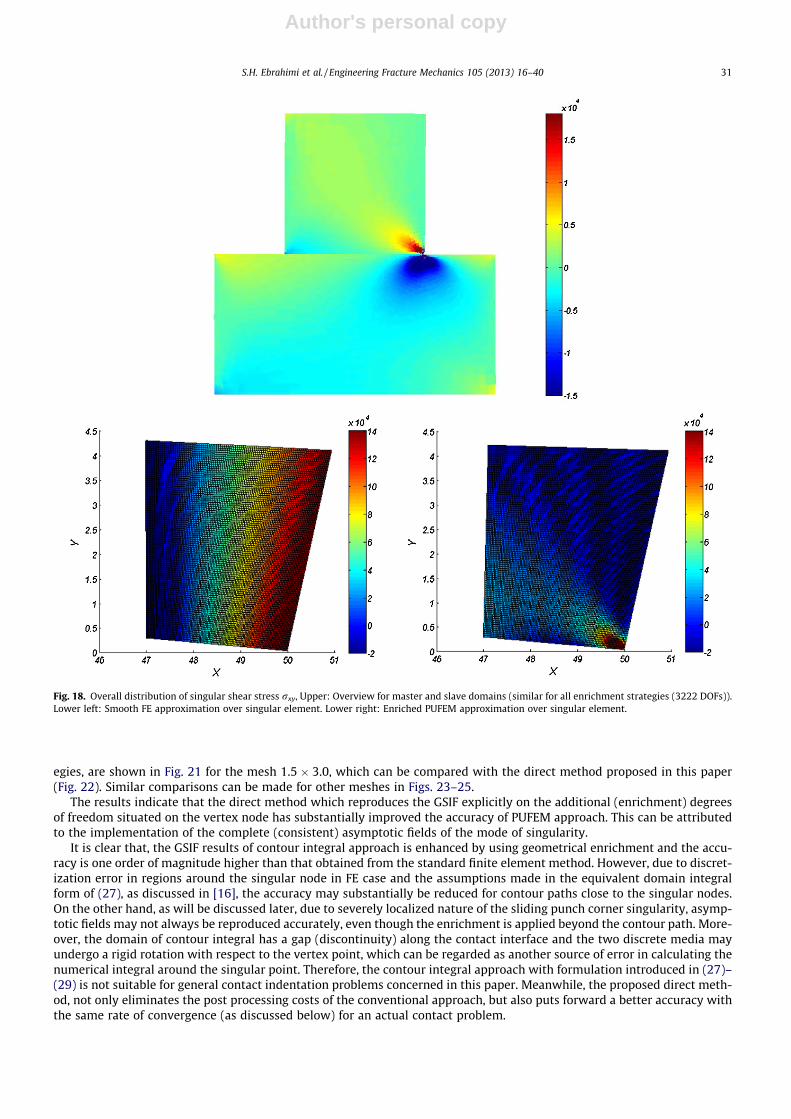
For the topological enrichment, only three elements of the mesh are enriched (1 slave and 2 target elements ), whereas for geometric enrichme nt, all elements within a fixed radius of enrichment of re = 3 cm are enriched (comprising 5 elements; 1slave and 4 target elements). The overall view of the shear stress rxy contour and its distribution over the singular slave ele- ment (see Fig. 17) for the standard FE and geometrically enriched PUFE cases are shown in Fig. 18. It is obvious that the PU- FEM solution represents the exact localized field, whereas in the standard FE case a smooth stress field is generated, which overestimat es the exact solution in regions far away from the singular point (D) and underest imates that significantly around the singular point. Clearly, the enriched cases are capable of describin g the singularity in contrast to the standard FEM. The local distribution of the reproduced singular field in the enriched element is visualized in Fig. 19, where a local region of dimensions 0.1% of the interface width has been selected to illustrate the local stress field.
To examine the effect of discretization, the generalized stress intensity factor is derived with both approach es for differ- ent meshes of the master and slave bodies, as typically depicted in Fig. 20. The order of Gauss points for the enriched and blending elements (elements which are partially enriched) is 2 � 2 with 25 � 25 sub-quads and 2 � 2 for the standard finiteelements. Results of GSIF, obtained from the contour integral approach for FEM and PUFEM with different enrichment strat-
Fig. 17. A sliding problem simulated by the present PUFEM.
30 S.H. Ebrahimi et al. / Engineering Fracture Mechanics 105 (2013) 16–40
Author's personal copy
egies, are shown in Fig. 21 for the mesh 1.5 � 3.0, which can be compared with the direct method proposed in this paper (Fig. 22). Similar comparisons can be made for other meshes in Figs. 23–25.
The results indicate that the direct method which reproduces the GSIF explicitly on the additional (enrichment) degrees of freedom situated on the vertex node has substantially improved the accuracy of PUFEM approach. This can be attributed to the implementati on of the complete (consistent) asymptotic fields of the mode of singularity.
It is clear that, the GSIF results of contour integral approach is enhanced by using geometri cal enrichment and the accu- racy is one order of magnitude higher than that obtained from the standard finite element method. However, due to discret- ization error in regions around the singular node in FE case and the assumptions made in the equivalent domain integral form of (27), as discussed in [16], the accuracy may substanti ally be reduced for contour paths close to the singular nodes.On the other hand, as will be discussed later, due to severely localized nature of the sliding punch corner singularity, asymp- totic fields may not always be reproduced accurately, even though the enrichment is applied beyond the contour path. More- over, the domain of contour integral has a gap (discontinuity) along the contact interface and the two discrete media may undergo a rigid rotation with respect to the vertex point, which can be regarded as another source of error in calculatin g the numerical integral around the singular point. Therefore, the contour integral approach with formulation introduce d in (27)–(29) is not suitable for general contact indentation problems concerned in this paper. Meanwhi le, the proposed direct meth- od, not only eliminates the post processin g costs of the conventional approach , but also puts forward a better accuracy with the same rate of convergence (as discussed below) for an actual contact problem.
Fig. 18. Overall distribution of singular shear stress rxy, Upper: Overview for master and slave domains (similar for all enrichment strategies (3222 DOFs)).Lower left: Smooth FE approximation over singular element. Lower right: Enriched PUFEM approximation over singular element.
S.H. Ebrahimi et al. / Engineering Fracture Mechanics 105 (2013) 16–40 31

Author's personal copy
As mentioned before, the most important advantage of the local enrichment of finite element interpolation space is toachieve a more precise estimation of the GSIF parameter. Enrichment gives the opportunity to produce the expected higher order field locally by a relatively coarse mesh. However , in contrast to the crack-tip asymptotic field which is controlle d bythe local boundary conditions along one direction, the boundary conditions along at least two directions are effective inreproducing the asymptotic fields in a punch-subs trate sliding corner. For this reason, the process zone of the stress singu- larity in contact corners has a limited length compared with the crack problem. Enrichment functions of the crack problem orany singular contact configuration participate in the finite element solution due to satisfaction of their respective boundary conditions. Consisten t asymptoti c fields, the finite element mesh and other implicit enrichment functions introduce the boundary conditions that should be compatib le with each other to generate the expected solution. On one hand, the dis- placement-b ased finite element method has negligible control on the stress state, specially to satisfy boundary condition ssuch as rð1Þrh þ lf r
ð1Þhh ¼ 0 with the NTS penalty method, while on the other hand, other interface conditions i.e.
rð1Þrh ¼ rð2Þrh ;rð1Þhh ¼ rð2Þhh ; uð1Þh ¼ uð2Þh which describe the contact interactio n of the slave and target bodies, necessita te an implicit contact interface definition or at least, a high resolution of the state variables on the interface when contact faces are definedexplicitly via the PUFEM strategy. As a result, the enriched element, attributed to the singular vertex node, is theoreticall ymore eligible to reproduce the asymptotic fields.
Fig. 19. Local approximation of the singularity, Left: Finite Element and Right: Enriched PUFEM.
Fig. 20. Mesh 1.8 � 4.0; 776 nodes, 700 elements (left), mesh 0.9 � 2.0; 3138 nodes, 2986 elements (right).
32 S.H. Ebrahimi et al. / Engineering Fracture Mechanics 105 (2013) 16–40

Author's personal copy
Fig. 25 compares the accuracy of GSIF of the direct method as opposed to the contour integral method for two similar meshes versus different enrichment radius (for the direct method) or contour integral band radius (for the contour integral method). It should be mentioned that due to singular/high gradient fields within the span of enrichme nt functions, error inadditional unknowns, attributed to the enriched degrees of freedom, can disturb the solution precision. Therefore, a suffi-ciently higher order of integration is required in enriched elements to control the local error. Effect of the order of Gauss integration on the rate of convergence is examined in Fig. 26. Since the standard Gauss quadrature is not consisten t with non-polyno mial shape functions, in order to minimize the error of integration of a singular field near the slave singular node and master element boundary, all enriched elements are subdivid ed to quads. In contrary to sub-triangu lation, sub-quad smaintain the address of the initial Gauss points during the increments of a nonlinear procedure and so that the tracking of path-depen dent paramete rs are facilitated.
The smoothed rate of mesh size convergence of the finite element and different PUFEM simulations is demonstrat ed inFig. 26. A linear regression is performed to determine an equivalent converge nce rate for the oscillating results, which can beattributed to the mesh sensitivity of the local solution and unstructured mesh discretiza tion. The ratio of the element size on
Fig. 21. Accuracy of the contour integral for various domain integral radius rq (mesh 1.5 � 3.0; 1316 nodes, 1220 elements).
Fig. 22. Accuracy of the direct and contour integral approaches versus enrichment radius re (mesh 1.5 � 3.0; 1316 nodes, 1220 elements).
S.H. Ebrahimi et al. / Engineering Fracture Mechanics 105 (2013) 16–40 33

Author's personal copy
the interface has been considered to be five times smaller than that on the upper and lower boundaries. It is clearly observed that the results of the direct method for geometri cal enrichme nt is more precise with far improved rate of convergence incomparison with the direct method with topological enrichme nt. Significant enhancements are observed for both cases com- pared with the conventional finite element method with contour integral GSIF estimates.
Fig. 23. Accuracy of GSIF for a coarse mesh (mesh 1.8 � 4.0; 776 nodes, 700 elements). Contour Integral versus domain integral band (left), Collocated GSIF versus enrichment radius (right).
Fig. 24. Accuracy of GSIF for a fine mesh (mesh 0.9 � 2.0; 3138 nodes, 2986 elements). Contour Integral versus domain integral band (left), Collocated GSIF versus enrichment radius (right).
Fig. 25. Comparison of the accuracy of contour integral method with the present direct method.
34 S.H. Ebrahimi et al. / Engineering Fracture Mechanics 105 (2013) 16–40

Author's personal copy
In Fig. 26, the enrichme nt radius for geometri cal enrichme nt is re/d = 0.1 and a 2 � 2 quadrature on 10 � 10 � Q4 subcells is performed on enriched and blending elements . The results show that by local enriching the approximat ion in geometrical enrichment PUFEM, the rate of convergence of the standard Q4 finite element for non-singula r problems can be reproduced.The convergence of PUFEM varies averagely between �0.5 and �2.0 for different quadrature orders and unstructured mesh densities.
The average error of GSIF, determined by the contour integral at rq/d = 0.05 (where rq is the contour integral radius and dis the interface width) and the rate of convergence for different Gauss quadrature orders have been compare d in Table 3 forthe standard finite element simulatio n.
In order to verify the rate of convergence of contour integral results in enriched PUFEM, different radii of enrichment have been considered. While the GSIF is calculated at the same radius rq/d = 0.05, the enrichme nt is performed over different pro- cess zone radiuses of re=d ¼ 0:1;0:2. So, the enriched zone covers the contour integral path. The results show that any enrich- ment of the process zone beyond re/d = 0.1 has a negligible effect on accuracy and rate of converge nce of GSIF generated atradius rq/d = 0.05.
The rate of convergence and average error in contour integral GSIF (rq/d = 0.05, 0.10), for different quadrature orders are presented in Tables 4 and 5 for re/d = 0.1, 0.2. The results show a good agreement with [16] with reasonably higher resolution of structured mesh.
The convergence rate versus different Gauss point densities over the enriched nodes is presented in Tables 6 and 7 for the topological and geometrical enrichment PUFEM (direct method), respectively . The convergence curves established for vari- ous orders of local integration confirm the convergence rate and mean accuracy of direct GSIF. Comparis on of the mean accu- racy of GSIF in Tables 3–5, 6 and 7 clearly indicates the superiority of the proposed approach . Mean Error of GSIF in Tables 3–6 is obtained from meshes with number of DOFs between 600 and 6000.
The third numerical example studies the performance of the implemented PUFEM in analyzing a steel punch sliding over a steel substrate and compares it by a non-enri ched case with a relatively refined mesh to resemble the exact solution. The example evaluates the variations of GSIF through the loading steps by means of internal stress contours and the rate of con- vergence of residuals in each incremen t. The geometric nonlinearity is fulfilled via an updated Lagrangian procedure. During the load incremen ts, top surface of the punch and bottom edge of the substrate is constrained and a compressive load, fol- lowed by a series of sway displacemen t-control loadings are applied to the prescribe d nodes of the punch. Outline of the problem is depicted in Fig. 27, with 900 nodes and 803 elements.
Enrichme nts are applied to nodes within a radius of re = 10 m. The domain integration approach to derive KGSIF with the contour integral method is performed over a surrounding strip of elements within the enrichme nt radius. In order to obtain
Fig. 26. Comparison of smoothed convergence curve for the standard FEM(Q4) and direct PUFEM with Topological Enrichment (T.E.) and direct PUFEM with Geometrical Enrichment (G.E.), (leading edge k ¼ 0:179, Q2 � N � N stands for Quadrature 2 � 2, Subdivision 20 � 20).
Table 3Comparison of mesh size convergence rates of FEM for GSIF versus quadrature order.
Quadrature order, subdivision 2, 5 � 5 2, 10 � 10 2, 15 � 15 2, 20 � 20
Smoothed convergence rate �0.50 �0.42 �0.32 �0.22 Mean error of GSIF (%) 74 68 67 67
S.H. Ebrahimi et al. / Engineering Fracture Mechanics 105 (2013) 16–40 35

Author's personal copy
KGSIF with a maximum 5% error with respect to the direct method, a topological enrichment is adequate. The total number ofadditional degrees of freedom is 122 (2 per enriched node). Asterisk nodes around the left and right punch corners in Fig. 27show the enriched nodes. The normal and tangential penalty factors are 5 � 105. This parameter should be tuned in order toallow reasonably low number of iterations to reach convergence in each increment. A low penalty parameter decreases the accuracy of impenetrab ility constraint enforcement while high penalty values decrease the rate of convergence through increasing the contact interface residuals and bouncing between the free and slip contact states of slave nodes. The coeffi-cient of friction is considered lf = 0.3. Inertia effects are neglected and a quasi static loading sequence is described according to Table 8.
Table 4Comparison of mesh size convergence rates of PUFEM for GSIF versus quadrature order rq=d ¼ 0:05; re=d ¼ 0:10.
Quadrature order, subdivision 2, 5 � 5 2, 10 � 10 2, 15 � 15 2, 20 � 20
Smoothed convergence rate �0.69 �0.93 �0.54 �0.93 Mean error in GSIF (%) 17 20 18 22
Table 5Comparison of mesh size convergence rates of PUFEM for GSIF versus quadrature order rq=d ¼ 0:10; re=d ¼ 0:20.
Quadrature order, subdivision 2, 5 � 5 2, 10 � 10 2, 15 � 15 2, 20 � 20
Smoothed convergence rate �0.95 �0.59 �0.86 �0.94 Mean error in GSIF (%) 8 13 11 11
Table 6Mesh size convergence rates for different quadrature order , the case of the topological enriched PUFEM.
Quadrature order, subdivision 2, 5 � 5 2, 10 � 10 2, 15 � 15 2, 20 � 20
Convergence rate �0.10 �0.09 �0.17 �0.10 Mean error in GSIF (%) 10 8 8 7
Table 7Mesh size convergence rates for different quadrature order , the case of the geometrical enriched PUFEM (re/d = 0.10).
Quadrature order, subdivision 2, 5 � 5 2, 10 � 10 2, 15 � 15 2, 20 � 20
Convergence rate �1.05 �1.34 �0.81 �1.12 Mean error in GSIF (%) 6 4 6 4
Fig. 27. Configuration of the Punch sliding problem. fine finite element mesh (left) and geometrically enriched PUFE mesh (right).
36 S.H. Ebrahimi et al. / Engineering Fracture Mechanics 105 (2013) 16–40

Author's personal copy
The real and imaginary parts of the characteristic equation for leading and trailing corners of steel/stee l slave/maste rcases are described in Fig. 28. The singulari ty power is k ¼ 0:5539 for the leading corner and k ¼ 0:9799 for the trailing corner.
The variations of the residuals of the standard FE and geometric enriched PUFEM are illustrate d in Fig. 29. In Fig. 29(right), variations of the residuals of FEM and geometric PUFEM are compare d. The results show that adding the enrichment function accelerates the convergence of the Newton–Raphson iteration s within each sub-step and decreases the number ofiterations to 1/5 of conventional FEM.
The overall contours of stress and strain fields for a number of successive increments to the end of the procedure are shown in Fig. 30, clearly indicating the singularity nature of all stress components at the contact corners.
Fig. 31 illustrates variations of GSIF for the trailing (left) and leading (right) corners for different loading steps are calcu- lated via the contour integral over 5 m radius band of elements in the FE post-proces sing stage and collocation unknown s inPUFEM solution.
Table 8Sequence of displacement-controlled loading of the punch.
Increment 1 2–30
Dx (m) 0.5 0.5 Dy (m) �0.2 0
Fig. 28. Results of characteristic equation for steel punch/steel substrate and lf = 0.3 (solid and dash lines trace the zeros of the real and imaginary parts ofthe characteristic Eq. (8), respectively). Trailing corner (left), Leading corner (right).
Fig. 29. Convergence of the residual norm during iterations. Finite element procedure (left) Comparison between FEM and PUFEM (right).
S.H. Ebrahimi et al. / Engineering Fracture Mechanics 105 (2013) 16–40 37

Author's personal copy
As explained before, due to extremely local extension of the singular stress field around the vertex point, the interaction contour integral method does not reproduce the exact GSIF. It is observed that the GSIF estimate made by the interactio ncontour integral method in punch sliding problem is less accurate than that in the correspondi ng benchma rk problem where the asymptotic boundary condition s are enforced on the slave and target boundaries. However , the GSIFs predicted by the direct method on the singular element gives the sole approximat e of the real stress intensity factor which is expected to begenerated at the singular vertex point. Despite the fact that the reliability of the GSIF results depends on the method of con- straint enforcemen t (penalty, Lagrange multiplier s, etc.), the predictions by the proposed method have the advantag e ofbeing independen t of the radius of contour integral and the enrichment band radius and removes the cost of post-pro cessing calculations around the singular point to estimate the failure design parameters (i.e. GSIF), because an unconditional ly stable result is derived directly over the collocated enriched degrees of freedom.
6. Conclusi on
The consistent asymptotic fields for a sliding punch corner have been solved numerically and applied as enrichment func- tions within a PUFEM framework. It is indicated that implementati on of the enrichments in the compatible form, which sat-
Fig. 30. Contour plot for the first (Upper) and the last (Lower) increments. Left: rxx, Middle: ryy, Right: rxy.
Fig. 31. Variation of KGSIF for different stages of punch slide. Left: Trailing edge k ¼ 0:9799 and Right: Leading edge k ¼ 0:5539.
38 S.H. Ebrahimi et al. / Engineering Fracture Mechanics 105 (2013) 16–40

Author's personal copy
isfies the local boundary conditions, increases the accuracy of GSIF derived from the contour integral method, with minimal additional degrees of freedom. Furthermore, the proposed definition of enrichment function eliminates the need for facili- tating contour integral method in the post-processing phase, because GSIF can be computed accurately, as collocated addi- tional degrees of freedom located on the vertex point and its neighboring nodes and estimates the exact value with anegligible error. The effects of topological and geometric enrichments on the rate of convergence of the energy error norm and GSIF versus different local element size have been considered. Moreover, it is shown that the rate of convergence of the Newton Raphson iterations is improved in PUFEM approach. Variation of GSIF in a real sliding punch problem for different stages of loading is derived and superiority of the consistent enrichment function over previously available incompatible enrichment strategy is demonst rated. For other cases of contact problems including sharp corners with different boundary conditions such as slip-free indentation of cutting tools, symmetric sliding cone penetration, where neither a closed form solution nor a definite reduced form of the characterist ic equation is addressed in literature, impleme ntation of the present PUFEM remains applicable and straightforwar d.
Acknowled gements
The authors would like to acknowled ge the technical support of the High Performa nce Computing Lab, School of Civil Engineering, University of Tehran. Also, the financial support of Iran National Science Foundation (INSF) is gratefully acknowledged .
References
[1] Yosibash Z, Szabo BA. A note on numerically computed eigenfunctions and generalized stress intensity factors associated with singular points,Technical note. Engng Fract Mech 1996;54(4):593–5.
[2] Sternberg E, Koiter V. The wedge under a concentrated couple: a paradox in the two-dimensional theory of elasticity. J Appl Mech-T ASME 1958;25:575–81.
[3] Barber JR. Elasticity. 2nd ed. New York: Kluwer Academic Publishers; 2004 .[4] Brahtz JAH. Stress distribution in a reentrant corner. Trans Am Soc Mech Eng 1933;55:31–7.[5] Williams ML. Stress singularities resulting from various boundary conditions in angular corners of plates in extension. J Appl Mech 1952;19:526–34.[6] Karal FC, Karp JR. The elastic-field behavior in the neighborhood of a crack of arbitrary angle. Commun Pure Appl Math 1962;15(4):413–21.[7] Kalandiia AI. Remarks on the singularity of elastic solutions near corners. Priklandnaya Matematika y Mekanika 1969;33:132–5. English translation .[8] England AH. On stress singularities in linear elasticity. Int J Engng Sci 1971;9(6):571–85.[9] Vasilopoulos D. Stress computations at reentrant corners ⁄Developments in Mechanics. In: Swodel W, Hamilton JF, editors. Proceedings 20th
midwestern mechanical conference. Purdue University; 1987. p. 1085–90.[10] Vasilopoulos D. On the determination of higher order terms of singular elastic stress fields near corners. Numer Math 1988;53:51–95.[11] Vasilopoulos D. An algorithm for the eigenvalues of a fixed-fixed reentrant corner. Engng Fract Mech 1990;37:839–51.[12] Dempsey JP, Sinclair GB. On the stress singularity in the plane elasticity of a composite wedge. J Elast 1979;9(4):373–91.[13] Joseph PF, Zhang N. Multiple root solutions, wedge paradoxes and singular stress states that are not variable-separable. Compos Sci Technol
1998;58(11):1839–59.[14] Dini D, Barber JR, Churchman CM, Sackfield A, Hills AD. The application of asymptotic solutions to contact problems characterized by logarithmic
singularities. Eur J Mech A Solids 2008;27(5):847–58.[15] Ying X, Katz IN. A uniform formulation for the calculation of stress singularities in the plane elasticity of a wedge composed of multiple isotropic
materials. Comput Math Appl 1987;14(6):437–58.[16] Giner E, Sukumar N, Fuenmayor FJ, Vercher A. Singularity enrichment for complete sliding contact using the partition of unity finite element method.
Int J Numer Meth Engng 2008;76(9):1402–18.[17] Rabczuk T, Zi G, Bordas S, Nguyen-Xuan H. A geometrically non-linear three-dimensional cohesive crack method for reinforced concrete structures.
Engng Fract Mech 2008;75:4740–58.[18] Bordas S, Rabczuk T, Zi G. Three-dimensional crack initiation, propagation, branching and junction in non-linear materials by an extended meshfree
method without asymptotic enrichment. Engng Fract Mech 2007;75(5):943–60.[19] Rabczuk T, Areias PMA, Belytschko T. A meshfree thin shell method for non-linear dynamic fracture. Int J Numer Meth Engng 2007;72:524–48.[20] Rabczuk T, Belytschko T. Cracking particles: a simplified meshfree method for arbitrary evolving cracks. Int J Numer Meth Engng 2004;61:2316–43.[21] Rabczuk T, Belytschko T. A three-dimensional large deformation meshfree method for arbitrary evolving cracks. Comput Methods Appl Mech Engng
2007;196:2777–99.[22] Rabczuk T, Bordas S, Zi G. A three-dimensional meshfree method for continuous multiple-crack initiation, propagation and junction in statics and
dynamics. Comput Mech 2007;40:473–95.[23] Rabczuk T, Gracie R, Song JH, Belytschko T. Immersed particle method for fluid-structure interaction. Int J Numer Meth Engng 2010;81:48–71.[24] Menk A, Bordas S. Numerically determined enrichment functions for the extended finite element method and applications to bi-material anisotropic
fracture and polycrystals. Int J Numer Meth Engng 2010;83:805–28.[25] Li J, Zhang XB, Recho N. Stress singularities near the tip of a tow dimensional notch formed from several elastic anisotropic materials. Int J Fract
2001;107(4):379–95.[26] Miniatt EC, Waas AM, Anderson WJ. An experimental study of stress singularities at a sharp corner in a contact problem. Exp Mech 1990;30(3):281–5.[27] Lee D, Barber JR. An automated procedure for determining asymptotic elastic stress fields at singular points. J Strain Anal Engng Des
2006;41(4):287–95.[28] Wieghardt K. Über das spalten und zerreissen elastischer kÖrper. Z Math Phys 1907;55:60–103.[29] Gdoutos EE, Theocaris PS. Stress concentration at the apex of a plane indenter acting on an elastic half-plane. J Appl Mech 1975;42:688–92.[30] Comninou M. Stress singularity at a sharp edge in contact problems with friction. J App Math Phys (ZAMP) 1976;27:493–9.[31] Wu Z, Liu Y. Singular stress field near interface edge in orthotropic/isotropic bi-materials. Int J Solids Struct 2010;47(17):2328–35.[32] Asadpoure AA, Mohammadi S, Vafai A. Modeling crack in orthotropic media using a coupled finite element and partition of unity methods. Finite Elem
Anal Des 2006;42(13):1165–75.[33] Asadpoure AA, Mohammadi S, Vafai A. Crack analysis in orthotropic media using the extended finite element method. Thin-Walled Struct
2006;44(9):1031–8.[34] Asadpoure AA, Mohammadi S. Developing new enrichment functions for crack simulation in orthotropic media by the extended finite element
method. Int J Numer Meth Engng 2007;69(10):2150–72.
S.H. Ebrahimi et al. / Engineering Fracture Mechanics 105 (2013) 16–40 39

Author's personal copy
[35] Motamedi D, Mohammadi S. Fracture analysis of composites by time independent moving-crack orthotropic XFEM. Int J Mech Sci 2010;54(2012):20–37.
[36] Esna Ashari S, Mohammadi S. Delamination analysis of composites by new orthotropic bimaterial extended finite element method. Int J Numer Meth Engng 2011;86(13):1507–43.
[37] Mohammadi S. Extended finite element method for fracture analysis of structures. UK: Wiley/Blackwell; 2008 .[38] Mohammadi S. XFEM fracture analysis of composites. UK: Wiley; 2012 .[39] Bogy DB, Wang KC. Stress singularities at interface corners in bonded dissimilar isotropic elastic materials. Int J Solids Struct 1971;7(8):993–1005.[40] Wriggers P. Computational contact mechanics. 2nd ed. England: John Wiley & Sons; 2002 .[41] Sheng D, Sloan SW. Load stepping methods for critical state models. Int J Numer Meth Engng 2001;50(1):67–93.[42] Sheng D, Wriggers P, Sloan SW. Improved numerical algorithms for frictional contact in pile penetration analysis. Comput Geotech 2006;33(6–
7):341–54.[43] Dundurs J, Lee MS. Stress concentration at a sharp edge in contact problems. J Elast 1972;2(2):109–12.[44] Karuppanan S, Hills DA. Sliding of general frictional complete contacts. Int J Mech Sci 2008;50(9):1404–10.[45] Melenk JM, Babuska I. The partition of unity finite element method: basic theory and applications. Research report No. 96–01. Seminar fur Angewandte
Mathematic Eidgenossische Technische Hochschule; 1996.[46] Babuska I, Melenk JM. The partition of unity method. Int J Numer Meth Engng 1997;40(4):727–58.[47] Saouma VE. Lecture notes in fracture mechanics. Department of Civil, Environmental and Architectural Engineering, University of Colorado; 2000 .
40 S.H. Ebrahimi et al. / Engineering Fracture Mechanics 105 (2013) 16–40


![Singularity - easybuilders.github.ioeasybuilders.github.io/easybuild/files/EUM17/20170208-1_Singularity… · Singularity Workflow 1. Create image file $ sudo singularity create [image]](https://static.fdocuments.in/doc/165x107/5f0991027e708231d4277151/singularity-singularity-workflow-1-create-image-file-sudo-singularity-create.jpg)


![[William Sleator] Singularity](https://static.fdocuments.in/doc/165x107/5466dabbb4af9f4e3f8b55e2/william-sleator-singularity.jpg)