A Light-weight Event-driven Protocol for Sensor Clustering in Wireless Camera Networks
8
A LIGHT-WEIGHT EVENT-DRIVEN PROTOCOL FOR SENSOR CLUSTERING IN WIRELESS CAMERA NETWORKS Henry Medeiros, Johnny Park and Avinash Kak School of Electrical and Computer Engineering Purdue University, West Lafayette, Indiana 47907-2035 {hmedeiro, jpark, kak}@purdue.edu ABSTRACT We propose a light-weight event-driven protocol for wireless camera networks to allow for formation and propagation of clusters of cam- eras for the purpose of collaborative processing during object track- ing. Cluster formation is triggered by the detection of objects with specific features. Our protocol allows for simultaneous formation and propagation of multiple clusters. Cameras being directional de- vices, more than one cluster may track a single object since groups of cameras outside each others communication range may see the same object. Entry into a cluster and cluster membership maintenance re- quire a sensor node to confirm the presence of features of the object being tracked. Each cluster elects its own leader among the cameras that observe the same target. When a cluster leader loses track of an object, it assigns the leadership role to another cluster member. To avoid high communication overhead among cluster members, single- hop clusters are formed, i.e., every member of a cluster is within the communication range of the cluster head. We have implemented a simple version of this protocol on a test-bed and provide an experi- mental evaluation. Index Terms— sensor clustering, object tracking, collaborative processing 1. INTRODUCTION Previous work on sensor clustering has focused primarily on extend- ing the lifetime of a network by partitioning it into clusters to enable data aggregation at a local level [1], [2]. When sensor networks are used for event-driven applications (as opposed to environment moni- toring applications), not all sensors provide useful information at the same time. The goal in event-driven clustering is to select a subset of sensors that maximize some information function that depends on the position of the event source and on the characteristics of the sensors. This function must be maximized while the cost related to exchanging information among cluster members is minimized [3]. Most of the current event-driven clustering algorithms assume that the distances between the sensors and the event-generating tar- gets are somehow related to the information function mentioned above. In wireless camera networks, however, the distance-based criteria for sensor node clustering are not sufficient since, depend- ing on their pointing directions, physically proximal cameras may view segments of space that are disjointed and even far from one an- other. What that means is that even when only a single object is being tracked, a clustering algorithm must allow for the formation of mul- tiple disjointed clusters of cameras for tracking the same object. One of the primary contributions of our protocol is that it does allow for the formation and propagation of multiple clusters. When needed, the protocol also allows for clusters to coalesce into larger clusters and for large clusters to fragment into smaller clusters. Coalescence of clusters is made possible by the permitted overhearing of intra- cluster communications as different clusters come into each other’s communication range. Overhearing obviously implies inter-cluster communication. It is important to note that inter-cluster communi- cation can play a role in intra-cluster computation of a parameter of the environment even when cluster merging is not an issue. For example, a cluster composed of overhead cameras may request in- formation about the z coordinate of the target from a neighboring cluster composed of wall-mounted cameras. Object tracking is the specific focus of the camera clustering pro- tocol we present in this paper. Cluster formation is triggered by the detection of object features that are keyed to specific objects. Our protocol allows for simultaneous formation and propagation of mul- tiple clusters and interaction between them. Each cluster uses sim- ple selection rules to elect its own leader. When a cluster leader loses track of an object, it assigns the leadership role to one of its members that is in the best position to maintain a "lock" on the target object. In order to test its practical feasibility, we implemented a simple version of the protocol on a testbed consisting of 12 ceiling-mounted Cyclops [4] cameras attached to micaZ motes. This camera network was used to track a simple object scurrying around on the floor. This paper is organized as follows. The next section presents some of the related work on event-based cluster formation for collab- orative processing. In section 3 we present an overview of our work on cluster-based object tracking using wireless camera networks. In section 4 we present the proposed clustering protocol. In section 5 we present our testbed implementation. Section 6 then presents the experiments carried out using the testbed. Finally, in section 7, we conclude and discuss possible future extension of our work. 2. RELATED WORK Among the works that take into consideration external events in the cluster formation process, Chen et al. [5] have proposed an al- gorithm for distributed target tracking using acoustic information. Their system is composed of sparsely placed high-capability nodes and densely spaced low-end sensors. The high-capability nodes act as cluster heads and the low-end sensors as cluster members. Cluster heads close to the detected event become active with higher proba- bility than cluster heads that are farther from the event. Similarly, the probability that a cluster member sends data to the cluster head is proportional to its distance to the event. Fang et al. [6] have proposed a distributed aggregate management (DAM) algorithm in which nodes that detect energy peaks become cluster heads, and a tree of cluster members is formed by its neigh- 1-4244-1354-0/07/$25.00 c 2007 IEEE
Transcript of A Light-weight Event-driven Protocol for Sensor Clustering in Wireless Camera Networks

A LIGHT-WEIGHT EVENT-DRIVEN PROTOCOL FOR SENSOR CLUSTERING INWIRELESS CAMERA NETWORKS
Henry Medeiros, Johnny Park and Avinash Kak
School of Electrical and Computer EngineeringPurdue University, West Lafayette, Indiana 47907-2035
{hmedeiro, jpark, kak}@purdue.edu
ABSTRACT
We propose a light-weight event-driven protocol for wireless cameranetworks to allow for formation and propagation of clusters of cam-eras for the purpose of collaborative processing during object track-ing. Cluster formation is triggered by the detection of objects withspecific features. Our protocol allows for simultaneous formationand propagation of multiple clusters. Cameras being directional de-vices, more than one cluster may track a single object since groups ofcameras outside each others communication range may see the sameobject. Entry into a cluster and cluster membership maintenance re-quire a sensor node to confirm the presence of features of the objectbeing tracked. Each cluster elects its own leader among the camerasthat observe the same target. When a cluster leader loses track of anobject, it assigns the leadership role to another cluster member. Toavoid high communication overhead among cluster members, single-hop clusters are formed, i.e., every member of a cluster is within thecommunication range of the cluster head. We have implemented asimple version of this protocol on a test-bed and provide an experi-mental evaluation.
Index Terms— sensor clustering, object tracking, collaborativeprocessing
1. INTRODUCTION
Previous work on sensor clustering has focused primarily on extend-ing the lifetime of a network by partitioning it into clusters to enabledata aggregation at a local level [1], [2]. When sensor networks areused for event-driven applications (as opposed to environment moni-toring applications), not all sensors provide useful information at thesame time. The goal in event-driven clustering is to select a subsetof sensors that maximize some information function that dependson the position of the event source and on the characteristics of thesensors. This function must be maximized while the cost related toexchanging information among cluster members is minimized [3].
Most of the current event-driven clustering algorithms assumethat the distances between the sensors and the event-generating tar-gets are somehow related to the information function mentionedabove. In wireless camera networks, however, the distance-basedcriteria for sensor node clustering are not sufficient since, depend-ing on their pointing directions, physically proximal cameras mayview segments of space that are disjointed and even far from one an-other. What that means is that even when only a single object is beingtracked, a clustering algorithm must allow for the formation of mul-tiple disjointed clusters of cameras for tracking the same object. Oneof the primary contributions of our protocol is that it does allow forthe formation and propagation of multiple clusters. When needed,
the protocol also allows for clusters to coalesce into larger clustersand for large clusters to fragment into smaller clusters. Coalescenceof clusters is made possible by the permitted overhearing of intra-cluster communications as different clusters come into each other’scommunication range. Overhearing obviously implies inter-clustercommunication. It is important to note that inter-cluster communi-cation can play a role in intra-cluster computation of a parameterof the environment even when cluster merging is not an issue. Forexample, a cluster composed of overhead cameras may request in-formation about the z coordinate of the target from a neighboringcluster composed of wall-mounted cameras.
Object tracking is the specific focus of the camera clustering pro-tocol we present in this paper. Cluster formation is triggered by thedetection of object features that are keyed to specific objects. Ourprotocol allows for simultaneous formation and propagation of mul-tiple clusters and interaction between them. Each cluster uses sim-ple selection rules to elect its own leader. When a cluster leader losestrack of an object, it assigns the leadership role to one of its membersthat is in the best position to maintain a "lock" on the target object.
In order to test its practical feasibility, we implemented a simpleversion of the protocol on a testbed consisting of 12 ceiling-mountedCyclops [4] cameras attached to micaZ motes. This camera networkwas used to track a simple object scurrying around on the floor.
This paper is organized as follows. The next section presentssome of the related work on event-based cluster formation for collab-orative processing. In section 3 we present an overview of our workon cluster-based object tracking using wireless camera networks. Insection 4 we present the proposed clustering protocol. In section 5we present our testbed implementation. Section 6 then presents theexperiments carried out using the testbed. Finally, in section 7, weconclude and discuss possible future extension of our work.
2. RELATED WORK
Among the works that take into consideration external events in thecluster formation process, Chen et al. [5] have proposed an al-gorithm for distributed target tracking using acoustic information.Their system is composed of sparsely placed high-capability nodesand densely spaced low-end sensors. The high-capability nodes actas cluster heads and the low-end sensors as cluster members. Clusterheads close to the detected event become active with higher proba-bility than cluster heads that are farther from the event. Similarly,the probability that a cluster member sends data to the cluster headis proportional to its distance to the event.
Fang et al. [6] have proposed a distributed aggregate management(DAM) algorithm in which nodes that detect energy peaks becomecluster heads, and a tree of cluster members is formed by its neigh-
1-4244-1354-0/07/$25.00 c©2007 IEEE
Michelle
Typewritten Text
Michelle
Typewritten Text
First ACM/IEEE International Conference on Distributed Smart Cameras, ICDSC '07. Vienna, Austria, 25-28 Sept. 2007

(a)(b)
Fig. 1. (a) Multiple clusters tracking the same object in a wirelesscamera network. (b) Two single-hop clusters in a network of cam-eras that can communicate in multiple hops. Blue (dark) circles rep-resent cluster heads, green (light) circles represent cluster members.The lines connecting the nodes correspond to communication linksamong them.
bors that detect lower energy levels. When many targets lie withinthe same cluster, Fang et al. use their energy-based activity monitor-ing (EBAM) algorithm to count the number of targets. By assuminga motion prediction model, they present a target-counting algorithmin which, as targets approach each other, their corresponding clus-ter heads exchange information and the clusters merge into a singlecluster.
In a previous contribution that is closely related to ours, Zhangand Cao propose the dynamic convoy tree-based collaboration(DCTC) [3] in which nodes that can detect an object create a treerooted at a node near the detected object. As the object moves, nodesare added to and pruned from the tree and the root moves to nodescloser to the object.
Blum et al. [7] have proposed a middleware architecture to allowfor distributed applications to communicate with groups of sensorsassigned to track multiple events in the environment. Their archi-tecture is divided into two modules, the entity management module(EMM) and the entity connection module (ECM). The EMM is re-sponsible for creating unique groups of sensors to track each event,to keep persistent identities to these groups, and to store informationabout the state of the event. The ECM provides end-to-end commu-nication among different groups of sensors.
3. OBJECT TRACKING WITH WIRELESS CAMERANETWORKS
Wireless camera networks allow for tracking of multiple objectsbased on their unique visual features. To be able to track the tar-gets robustly and precisely, resource-constrained wireless camerasmay need to collaborate to process information acquired from thetargets.
Clustering is a common technique for data aggregation and col-laborative processing in wireless sensor networks. In object track-ing applications, clusters are usually created to keep track of a spe-cific target. Once a cluster is created to track an object, connectionsamong cluster members can be established to allow for collaborativeprocessing.
Clustering in wireless camera networks gives rise to issues notpresent in networks of omnidirectional sensors. In a camera network,different sensors tracking the same object are not necessarily close
(a) (b)
Fig. 2. Fragmentation of a single cluster. As the cluster head in (a)leaves the cluster, it is fragmented into two clusters as illustrated in(b).
to one another, thus clusters may be created in different regions ofthe network to track the same object. An example is illustrated infigure 1 (a) where, in spite of the fact that the cameras in cluster Acannot communicate with the cameras in cluster B, both clusters ofcameras can track the object. Therefore, multiple clusters must beallowed to track the same target.
Even if all the cameras that can detect a common object can com-municate with one another in multiple hops, the communicationoverhead involved in tracking the object using a large cluster maybe unacceptable as collaborative processing requires, in general, in-tensive message exchange among the cluster members. Therefore,rather than requiring a single large multi-hop cluster to track an ob-ject, it is often desirable to have multiple single-hop clusters thatmay interact as needed.
Dynamic cluster formation requires all cluster members to inter-act to select a cluster head. There are many algorithms available[8],[9] that could be used for electing a leader from amongst all thecameras that are able to see the same object. But these algorithmswill not work for us since we must allow for the formation of mul-tiple clusters (for reasons previously explained) and for the electionof a separate leader for each cluster. As illustrated in figure 1 (b),whereas all the cameras that can see the same object may constitutea connected graph if you allow for multiple-hop communications,our protocol would require that two single-hop clusters be formed inthis case.
After clusters are created to track specific targets, these clustersmust be allowed to propagate through the network as the targetsmove. Cluster propagation refers to the process of accepting newmembers into the cluster as they identify the same object, removingmembers that can no longer see the object, and assigning new clus-ter heads as the current cluster head leaves the cluster. Since clusterpropagation is based on object features, it is possible for the clusterstracking different objects to propagate independently, or even over-lap if necessary. In other words, cameras that can detect multipletargets may belong simultaneously to multiple clusters. Including anew member into a cluster and removing an existing member froma cluster are rather simple operations. However, when a cluster headleaves the cluster, mechanisms must be provided to account for thepossibility that the cluster be fragmented into two or more clusters,as illustrated by figure 2.
Since multiple clusters are allowed to track the same target, ifthese clusters overlap they must be able to coalesce into a singlecluster. In addition, as these clusters approach each other, they mayinteract to exchange information about the state of the target to im-prove their estimates about the target position. Therefore, it is nec-essary to provide mechanisms to allow inter-cluster interactions inwireless camera networks.
To summarize these points, figure 3 illustrates the state transition

Fig. 3. State transition diagram of an object tracking system basedon our protocol
diagram of an object tracking system using a wireless camera net-work. The network initially monitors the environment. As an objectis detected, one or more clusters are formed to track this object. Tokeep track of the object, these clusters must propagate through thenetwork as the object moves and, if necessary, fragment themselvesinto smaller clusters. Finally, if two or more clusters tracking thesame object meet each other, they may interact to share informationor coalesce into larger clusters.
4. CLUSTERING PROTOCOL
We believe that the best way to present the protocol would be to showthe state transition diagram at each node. Such a diagram would de-fine all of the states of a node as it transitions from initial objectdetection to participation in a cluster, to possibly its role as a leader,and, finally, to relinquishing its membership in the cluster. Unfor-tunately, such a diagram would be much too large for the presenta-tion here. So instead we have opted to present this diagram in threepieces. The individual pieces we will present in this section corre-spond to the cluster formation and head election, cluster propaga-tion, and inter-cluster communications. The state transition diagramfor cluster propagation includes the transitions needed for cluster co-alescence and fragmentation. As the reader will note, our state tran-sitions allow for wireless camera networks to dynamically create oneor more clusters to track objects based on visual features. Note thatour protocol is light-weight in the sense that it creates single-levelclusters, i.e. clusters composed only of cameras that can communi-cate in a single hop, rather than multiple-level clusters, which incurlarge communication overhead and latency during collaborative pro-cessing and require complex cluster management strategies. Cam-eras that can communicate in multiple hops may share informationas needed by inter-cluster interactions.
4.1. Message Format
Figure 4 (a) shows the format of the messages used in the clusteringprotocol. Source and destination fields have obvious meanings. Thedestination field also allows a broadcast address so that messagesmay be transmitted to all the neighbors in the communication rangeof a node. The command field corresponds to the commands used inthe protocol. Connection number is a unique number defined by thecluster head to identify a connection to exchange information aboutan object. After clusters are formed, cluster members can use the
(a)(b)
Fig. 4. (a) Protocol message format. (b) Orphan cameras after thefirst stage of the leader election algorithm.
pair (cluster head identifier, connection number) to exchangeinformation with the cluster head about a specific object. The op-tions field contains command-specific information, such as the clus-ter leader election criteria. The features list length field specifies thelength of the object features list, which may vary depending on theapplication. Finally, the object features list field contains the list ofvisual object features used during clustering to uniquely identify anobject.
4.2. Cluster Head Election
To select cluster heads for single-hop clusters, we employ a two-phase cluster head election algorithm. In the first phase, nodes com-pete to find a node that minimizes (or maximizes) some criterion,such as the distance from the camera center to the object center inthe image plane. By the end of this phase, at most one camera ina single-hop neighborhood elects itself leader and its neighbors joinits cluster. During the second phase, cameras that were left with-out a leader (because their leader candidate joined another cluster)identify the next best leader candidate.
As illustrated by the state transition diagram on the left side offigure 5, in the first phase of the cluster head election algorithm,each camera that detects an object sends a message requesting thecreation of a cluster and includes itself in a list of cluster head can-didates sorted by the cluster selection criteria. The cluster creationmessage includes, in the options field, the value of the cluster selec-tion criteria from the sender. After a camera sends a cluster creationmessage, it waits for a predefined timeout period for cluster creationmessages from other cameras. Whenever a camera receives a clustercreation message from another camera, it updates the list of clusterhead candidates. To make sure that cameras that detect the objectat later moments do not lose information about the available clus-ter head candidates, all the cameras that can hear the create clustermessages update their candidates lists. After the end of the timeoutperiod, if the camera finds itself in the first position of the candidateslist, it sends a message informing its neighbors that it is ready to be-come the cluster head. If the camera does not decide to become acluster head, it proceeds to the second phase of the algorithm.
The first phase of the algorithm guarantees that a single camerachooses to become a cluster head within its communication range.However, it might be the case that cameras that can communicate tothe cluster head in multiple hops are left without a leader. Figure4 (b) shows an example of this situation. Cameras 1 and 2 decide

Fig. 5. Cluster head election state transition diagram.
that camera 3 is the best cluster head candidate. However, camera3 chooses to become a member of the cluster headed by camera 4.Hence, cameras 1 and 2 are left orphans after the first stage of theleader election and must proceed to the second phase of the algo-rithm to choose their cluster heads.
During the second phase of the cluster head election, cameras thatdid not receive a cluster ready message after a time interval removethe first element of the cluster head candidates list. If the camera thenfinds itself in the first position of the candidates list, it sends a clusterready message and becomes a cluster head. Otherwise, the camerawaits for a timeout period for a cluster ready message from the nextcandidate in the list. This process is illustrated in the right side ofthe state transition diagram of figure 5. Eventually, the camera willeither become a cluster head or join a cluster from a neighboringcamera. To avoid that multiple cameras decide to become clusterheads simultaneously, it is important that the cluster head electioncriteria impose a strict ordering to the candidates (if it does not, tiesmust be broken during the first phase).
The second phase of our leader election algorithm bears somesimilarities with Garcia-Molina’s bully election algorithm [10]. Asa consequence, the algorithm is not robust to communication fail-ures in the network. However, the consequences of communicationfailures are relatively mild in the sense that, as the algorithm termi-nates, every cluster will have exactly one cluster head, even if morethan one cluster is formed where a single cluster should. This prop-erty holds because each camera eventually chooses a cluster head,even if it is itself, and after receiving a cluster ready message froma cluster head, a camera no longer accepts cluster ready messages.Therefore, we believe that the simplicity of the algorithm overcomesits lack of robustness.
In the final step of the algorithm, to establish a bidirectional con-nection among the cluster head and its members, each member sendsa message to report the cluster head that it joined the cluster. Thisstep is not strictly necessary if the cluster head does not need to knowabout the cluster members. However, in general, for collaborativeprocessing, the cluster head needs to know its cluster members sothat it can assign them tasks and coordinate the distributed process-ing.
Fig. 6. State transition diagram for cluster propagation.
4.3. Cluster Propagation
Inclusion of new members into active clusters takes place as fol-lows. When a camera detects a new target, it proceeds normallyas in the cluster formation step by sending to its neighbors a createcluster message and waiting for the election process to take place.However, if there is an active cluster tracking the same object in theneighborhood of this camera, the cluster head replies with a messagerequesting the camera to join its cluster. The camera that initiated theformation of a new cluster then halts the election process and replieswith a join cluster message.
If there are multiple cluster heads near a camera that has detecteda target, the camera could, at the cost of a unit of time delay, choosethe cluster head which is closest to the target and become its member.However, we believe that during cluster propagation an extra waitingperiod would degrade the tracking performance. Hence, we allow anew camera (that has just seen the target) to simply join the clusterwhose cluster head first responds to the camera.
Removal of cluster members is trivial, when the target leaves thefield of view of a cluster member, all it has to do is send a messageinforming the cluster head that it is leaving the cluster. The clusterhead then updates its list of cluster members. If the cluster membercan track multiple targets, it terminates only the connection relatedto the lost target.
Figure 6 shows the state transition diagram for cluster propaga-tion. The diagram shows the transitions for inclusion and removal ofcluster members as well as cluster fragmentation and coalescence,which we explain below.
4.3.1. Cluster Fragmentation
When the cluster head leaves the cluster, we must make sure that,if the cluster is fragmented, each fragment will be assigned a newcluster head. Cluster head reassignment works as follows. We as-sume that the cluster head has access to the latest information aboutthe position of the target with respect to each cluster member and,consequently, is able to keep an updated list of the best cluster head

(a) (b)
Fig. 7. (a) Border nodes. (b) Messages transmitted to establish inter-cluster connections.
candidates. We also assume that cluster members know their neigh-bors. When the cluster head decides to leave the cluster, it sendsa message to its neighbors containing a sorted list of the best clus-ter head candidates. Each cluster member removes from that listall the nodes that are not within its neighborhood. Leader electionthen takes place as in the second phase of the regular cluster leaderelection mechanism.
4.3.2. Cluster Coalescence
When two clusters come within each other’s communication range,there can be two possible scenarios: 1) we may either have a non-coalescing inter-cluster interaction, or 2) the clusters may coalesceto form a larger cluster. We will address the non-coalescing inter-cluster interactions in the next section. As far as two clusters coa-lescing into one is concerned, our cluster head reassignment proce-dure allows for seamless cluster coalescence. Consider two clusters,A and B, that are propagating toward each another. As the reader willrecall, cluster propagation entails establishing a new cluster head asthe previous head loses sight of the object. Now consider the situ-ation when a camera is designated to become the new cluster headof cluster A and that this camera is in the communication range ofthe cluster head of B. Under this circumstance, the camera that wasmeant to be A’s new leader is forced to join cluster B. The mem-bers of cluster A that overhear their prospective cluster head joiningcluster B also join B. If there are members of cluster A that are notwithin the communication range of the cluster head of cluster B, theydo not join cluster B. Instead, they proceed to select another clusterhead for what remains of cluster A following the second phase of theregular cluster leader election mechanism.
4.4. Non-coalescing Inter-cluster Interaction
There are two possible cases in which clusters may need to interactwithout coalescing. In the first case, two clusters propagate towardseach other until their communication ranges overlap. The secondcase corresponds to the creation of a new cluster within the commu-nication range of an active cluster (see figure 1 (b) for an example).In any case, information can be shared among clusters through bor-der nodes. Border nodes correspond to nodes that can communicateto other nodes in two or more clusters, as illustrated in figure 7 (a).
As we explained in previous sections, clusters propagate as newcameras that detect an object being tracked by an active nearby clus-ter are forced to join that cluster. When two clusters approach eachother, these messages can be overheard by members of the neigh-boring cluster. As illustrated by the state-space diagram in figure 7
Fig. 8. Inter-cluster communication state transition diagram.
(b), when a member of an active cluster overhears a message (dashedline) of a camera which is tracking the same object joining a differ-ent cluster, it sends a message to its cluster head informing that itbecame a border node. It also informs the camera whose messagewas overheard that it should become a border node. This camera, byits turn, also informs its cluster head that it became a border node.
However, it is not sufficient for a border node to know that it is inthe communication range of some member of another cluster. As weillustrated in figure 7 (a), border nodes may communicate with mul-tiple border nodes. Therefore, it is necessary for each border nodeto keep track of how many connections it has to other clusters. Thiscan be achieved by simply incrementing a counter each time a newconnection among border nodes is established and decrementing itwhen a connection is terminated. Figure 8 shows the state transitiondiagram for inter-cluster communication.
When a cluster head is informed that one of its members becamea border node, it can, in effect, request information from the neigh-boring clusters as needed.
4.5. Cluster Maintenance
Additional robustness vis-a-vis communication failures is achievedby a periodic refresh of the cluster status. Since our protocol is de-signed for clusters to perform collaborative processing, we assumethat cluster members and cluster heads exchange messages periodi-cally. Therefore, we can use a soft-state based approach [11] to keeptrack of cluster membership. What that implies is that if the clusterhead does not hear from a member within a certain designated timeinterval, that membership is considered terminated (by the same to-ken, if a cluster member stops receiving messages from its clusterhead, it assumes the cluster no longer exists and starts the creationof its own cluster). If a specific application requires unidirectionalcommunication, i.e. communication only from head to members oronly from members to head, refresh messages can be sent by the re-ceiver side periodically to achieve the same soft-state based updatingof cluster membership.
Inter-cluster communication can also be maintained in a similarmanner. If a border node does not hear from nodes outside its owncluster for a predefined timeout period, it assumes it is no longer aborder node. If communication is unidirectional, border nodes canoverhear the explicit refresh messages sent by the neighboring clus-ter’s border nodes.
(a)
(b)
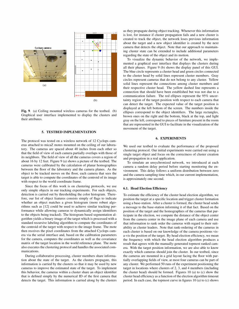
Fig. 9. (a) Ceiling mounted wireless cameras for the testbed. (b)Graphical user interface implemented to display the clusters andtheir attributes.
5. TESTBED IMPLEMENTATION
The protocol was tested on a wireless network of 12 Cyclops cam-eras attached to micaZ motes mounted on the ceiling of our labora-tory. The cameras are spaced about 40 inches from each other sothat the field of view of each camera partially overlaps with those ofits neighbors. The field of view of all the cameras covers a region ofabout 16 by 12 feet. Figure 9 (a) shows a picture of the testbed. Thecameras were calibrated by the calculation of planar homographiesbetween the floor of the laboratory and the camera planes. As theobject to be tracked moves on the floor, each camera that sees thetarget is able to compute the coordinates of the centroid of its imagewith respect to the world coordinate frame.
Since the focus of this work is on clustering protocols, we useonly simple objects in our tracking experiments. For such objects,detection is carried out by thresholding the color histogram. There-fore, our list of object features consists simply of flags to indicatewhether an object matches a given histogram (more robust algo-rithms such as [12] could be used to achieve similar tracking per-formance while allowing cameras to dynamically assign identifiersto the objects being tracked). The histogram based segmentation al-gorithm yields a binary image of the target which is processed with astandard recursive labeling algorithm to compute the coordinates ofthe centroid of the target with respect to the image frame. The motethen receives the pixel coordinates from the attached Cyclops cam-era via the serial interface and, based on the calibration parametersfor the camera, computes the coordinates as well as the covariancematrix of the target location in the world reference plane. The motealso executes the clustering protocol and handles the associated com-munications.
During collaborative processing, cluster members share informa-tion about the state of the target. As the clusters propagate, thisinformation is carried by the clusters so that it may be used by newcameras to improve the estimated state of the target. To implementthis behavior, the cameras within a cluster share an object identifierthat is defined simply by the numerical ID of the first camera thatdetects the target. This information is carried along by the clusters
as they propagate during object tracking. Whenever this informationis lost, for instance if cluster propagation fails and a new cluster iscreated to track the object, the network loses previous informationabout the target and a new object identifier is created by the nextcamera that detects the object. Note that our approach to maintain-ing cluster state can be extended to include additional parametersregarding the state of the object and its motion.
To visualize the dynamic behavior of the network, we imple-mented a graphical user interface that displays the clusters duringall their phases. Figure 9 (b) shows the display panel of this GUI.The blue circle represents a cluster head and green circles connectedto the cluster head by solid lines represent cluster members. Graycircles represent cameras that do not belong to any cluster. Yellowsolid lines represent the connections among cluster members andtheir respective cluster head. The yellow dashed line represents aconnection that should have been established but was not due to acommunication failure. The red ellipses represent the 95% uncer-tainty region of the target position with respect to each camera thatcan detect the target. The expected value of the target position isdisplayed at the left bottom of the screen. The numbers inside theellipses correspond to the object identifiers. The large rectangles,brown ones on the right and the bottom, black at the top, and lightgray on the left, correspond to pieces of furniture present in the roomthat are represented in the GUI to facilitate in the visualization of themovement of the target.
6. EXPERIMENTS
We used our testbed to evaluate the performance of the proposedclustering protocol. Our initial experiments were carried out using asingle target object and focus on the correctness of cluster creationand propagation in a real application.
To simulate an unsychronized network, we introduced at eachcamera a random delay period before starting monitoring the en-vironment. This delay follows a uniform distribution between zeroand the camera sampling time which, in our current implementation,is approximately one second.
6.1. Head Election Efficiency
To estimate the efficiency of the cluster head election algorithm, weposition the target at a specific location and trigger cluster formationusing a base-station. After a cluster is formed, the cluster head sendsa message to the base-station informing it of that fact. Based on theposition of the target and the homographies of the cameras that par-ticipate in the election, we compute the distance of the object centerfrom the camera center in the image plane of each camera and usethat information to rank order the cameras with regard to their suit-ability as cluster leaders. Note that rank-ordering of the cameras ineach cluster is based on our knowledge of the camera positions vis-a-vis the position of the target. By head election efficiency, we meanthe frequency with which the head election algorithm produces aresult that agrees with the manually-generated topmost ranked cam-era. With the target position information, we are also able to knowexactly which cameras should join the cluster. In our testbed, sincethe cameras are mounted in a grid layout facing the floor with par-tially overlapping fields of view, at most four cameras can be part ofany cluster. We performed 50 runs of the experiment positioning thetarget in locations where clusters of 2, 3, and 4 members (includingthe cluster head) should be formed. Figures 10 (a) to (c) show thecluster head efficiency as a function of the election algorithm timeoutperiod. In each case, the topmost curve in figures 10 (a) to (c) shows

(a) (b) (c)
Fig. 11. Average number of members that join a cluster of (a) 2, (b)3, and (c) 4 elements.
the average percentage of the time the camera elected to be head wasalso the topmost ranked camera. The curve below the first in eachfigure shows the percentage of the time the camera elected to be thehead was actually the second-ranked camera in the manual rankingprocess. Similarly, when more than two cameras are present in thecluster, the percentage of the time the third and fourth-ranked cam-eras were elected cluster heads are represented by the bottommostcurves.
There are two main reasons that contribute to the election of anincorrect leader. The first and most obvious is communication fail-ure. If the cluster ready message sent by the correct cluster head islost, a camera may join a cluster headed by a less suitable leader.The effects of communication failures are mitigated, however, bythe cluster coalescence process that forces such cameras to join thecluster headed by the best cluster head (as explained in subsection4.3.2). The second reason for the election of an incorrect leader isdue to the asynchronous nature of the network. If what would havebeen the correct cluster head did not acquire an image of the tar-get by the time a cluster is formed, it has no option but to join apreviously formed cluster headed by the next best camera. The pro-tocol itself does not offer any self-correcting measures for fixing thisproblem. This is corroborated by the fact that fewer incorrect clus-ter heads are elected when we increase the cluster formation timeoutperiod. In our implementation, for a timeout of approximately 60%of the sampling period of the cameras, the correct cluster head wasselected about 90% of the time. This problem is eliminated when thetimeout period is longer than the sampling period of the cameras. Ofcourse, the price to pay for that is the reduction in the overall speedwith which clusters would be able to follow a target (implying thatthere would be a limitation on the speed of the target if tracking is tobe successful). We believe that the performance of the algorithm canbe significantly improved (without incurring the speed penalty) if weimpose loose synchronization among cameras that can communicatein a single hop.
6.2. Cluster formation quality
Often, due to communication failures, not all cameras that shouldjoin a cluster actually do so. To quantify partially formed clusters,we used the same experimental setup used to evaluate the electionprocess as described in the previous section. In each message re-porting the formation of a cluster, the cluster head also includes alist of its current members. Figures 11 (a) to (c) show the averageover 250 runs of the experiment of the number of members (not in-cluding the cluster head) that joined the clusters for clusters of 2, 3,and 4 elements, respectively.
As in the previous experiment, the reasons for incomplete clus-ters are communication failures and the asynchronous nature of thenetwork. It is important to note that the results displayed in figure 11correspond to the status of the cluster immediately after the cluster
creation process has concluded. Subsequent cluster modificationsdue to cluster coalescence are not considered.
6.3. Tracking Efficiency
To evaluate the performance of the system while tracking an object,we move the object randomly and simultaneously compute the targetcoordinates using the wireless camera network and a firewire cameraat 30 frames per second. The data gathered by the firewire camerais used as ground truth. Figure 12 shows the trajectory of the objectfor three different runs of the experiment. The ground truth is repre-sented by the solid black line, the dashed lines show the trajectory ofthe target as computed by the wireless cameras. The markers placedon the dashed tracks correspond to the target positions computed bythe wireless cameras. We used different markers to illustrate the mo-ments when the wireless network loses track of the object and a newobject identifier is created, i.e., when cluster propagation fails and anew cluster is created to track the object.
7. CONCLUSION
We presented a light-weight event-driven clustering protocol forwireless cameras. As is well recognized, clustering is critical toenergy-efficient collaborative processing in sensor networks. Anyclustering protocol must address issues of cluster formation, prop-agation, coalescence, fragmentation, extinction, and interactionamong multiple clusters. Our protocol addresses all of these. We be-lieve that because cameras are directional devices, multiple clusterformation and coalescence are important for wireless camera net-works. Our protocol addresses all the phases in a single coherentframework.
Our future goals include a more formal analysis of the correct-ness and performance of the protocol under different conditions, es-pecially when the network is called upon to track multiple objectssimultaneously. We also intend to evaluate, using simulations, theperformance of the system in larger and denser networks. Besides,our protocol assumes that all cameras that can see the target join acluster. Nonetheless, it is possible to extend the protocol so that, af-ter a cluster is formed, the cluster head may choose which camerasit wishes to collaborate with using certain camera selection criteriabased on how well a camera sees a target [13], [14].
8. ACKNOWLEDGMENTS
This work was supported by Olympus Corporation.
9. REFERENCES
[1] S. Bandyopadhyay and E.J. Coyle, “An Energy Efficient Hier-archical Clustering Algorithm for Wireless Sensor Networks,”in Proc. IEEE INFOCOM, 2003.
[2] W. B. Heinzelman, A. P. Chandrakasan, and H. Balakrishnan,“An Application-Specific Protocol Architecture for WirelessMicrosensor Networks,” IEEE Transactions on Wireless Com-munications, vol. 1, pp. 660–670, Oct. 2002.
[3] W. Zhang and G. Cao, “DCTC: Dynamic Convoy Tree-BasedCollaboration for Target Tracking in Sensor Networks,” IEEETransactions on Wireless Communications, vol. 3, Sept. 2004.
[4] M. Rahimi, R. Baer, O. I. Iroezi, J. C. Garcia, J. Warrior, D.Estrin, and M. Srivastava, “Cyclops: in situ image sensing and

(a) (b) (c)
Fig. 10. Head election efficiency as a function of the timeout period for clusters of (a) 2, (b) 3, and (c) 4 members.
Fig. 12. Tracking performance for three different runs of the tracking experiment.
interpretation in wireless sensor networks,” in Proceedings ofthe 3rd international conference on Embedded networked sen-sor systems, 2005.
[5] W-P. Chen, J.C. Hou, and L. Sha, “Dynamic Clustering forAcoustic Target Tracking in Wireless Sensor Networks,” IEEETransactions on Mobile Computing, vol. 3, no. 3, 2004.
[6] Q. Fang, F. Zhao, and L. Guibas, “Lightweight Sensing andCommunication Protocols for Target Enumeration and Aggre-gation,” in ACM Symp. on Mobile Ad Hoc Networking andComputing (MobiHoc), 2003.
[7] B. Blum, P. Nagaraddi, A. Wood, T. Abdelzaher, S. Son, andJ. Stankovic, “An Entity Maintenance and Connection Servicefor Sensor Networks,” Proceedings of the 1st internationalconference on Mobile systems, applications and services (Mo-biSys), May 2003.
[8] N. Lynch, Distributed Algorithms. Morgan Kaufmann, 1997.
[9] Gerard Tel, Introduction to Distributed Algorithms. Cam-bridge, 1994.
[10] H. Garcia-Molina, “Elections in a Distributed Computing Sys-tem,” IEEE Transactions on Computers, vol. c-31, Jan. 1982.
[11] J. Kurose and K. Ross, Computer Networking: A Top-DownApproach Featuring the Internet. Addison Wesley, 3 ed., 2005.
[12] F. Lau, E. Oto, and H. Aghajan, “Color-Based Multiple AgentTracking for Wireless Image Sensor Networks,” in AdvancedConcepts for Intelligent Vision Systems (ACIVS), Sept. 2006.
[13] J. Park, P. C. Bhat, and A. C. Kak, “A Look-up Table BasedApproach for Solving the Camera Selection Problem in LargeCamera Networks,” in Workshop on Distributed Smart Cam-eras, in conjunction with ACM SenSys’06, 2006.
[14] A. O. Ercan, D. B. Yang, and A. El Gamal, “Optimal Place-ment and Selection of Camera Network Nodes for Target Lo-calization,” in Proceedings of the International Conference onDistributed Computing in Sensor Systems, 2006.