A Level-Encoded Transition Signaling Protocol for...
83
A Level-Encoded Transition Signaling Protocol for High-Throughput Asynchronous Global Communication Peggy B. McGee, Melinda Y. Agyekum, Moustafa M. Mohamed and Steven M. Nowick {pmcgee, melinda, mmohamed, nowick}@cs.columbia.edu Department of Computer Science Columbia University April 10, 2008 1/48
Transcript of A Level-Encoded Transition Signaling Protocol for...

A Level-Encoded Transition Signaling Protocolfor High-Throughput
Asynchronous Global Communication
Peggy B. McGee, Melinda Y. Agyekum, Moustafa M. Mohamedand Steven M. Nowick
{pmcgee, melinda, mmohamed, nowick}@cs.columbia.edu
Department of Computer ScienceColumbia University
April 10, 2008
1/48
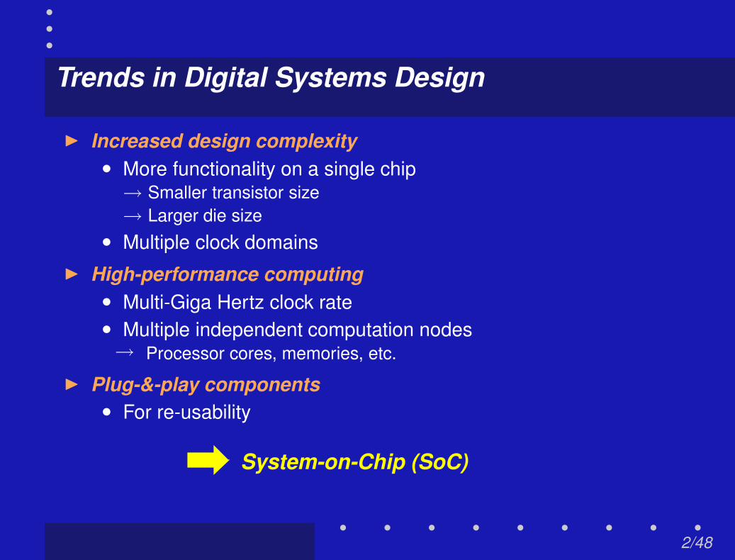
Trends in Digital Systems Design
I Increased design complexity• More functionality on a single chip
→ Smaller transistor size→ Larger die size
• Multiple clock domainsI High-performance computing
• Multi-Giga Hertz clock rate• Multiple independent computation nodes→ Processor cores, memories, etc.
I Plug-&-play components• For re-usability
System-on-Chip (SoC)
2/48

System-on-Chip (SoC): Challenges
I Heterogeneity• Multiple clock domains• Mixed asynchronous/synchronous components
I Wires do not scale at the same rate as transistors• Increasing proportion of delay in interconnects• Challenges for global routing in physical design
I Deep submicron effects• Handling dynamic timing variability, crosstalk, EMI, noise, etc.• Clock jittering and/or drifting effects
I Power dissipation• Interconnects a significant source of of power
Need for new approaches for interconnect design
3/48

SoC Communication Fabric: Ideal Requirements
I Speed• High throughput, low latency
I Low power• Low switching activity
I Robustness• Against timing variation• Handling dynamic voltage scaling• Handling single-event upset effects (soft errors)
I Flexibility• Easy integration of modular Intellectual Properties (IPs)
4/48

Asynchronous Design for SoC Communication
I Potential benefits of asynchronous design
• Significant power advantage→ No clock routing→ “Compute-on-demand” approach
• Timing robustness using delay-insensitive (DI) encoding→ Eliminates global timing constraints→ Accommodates uncertainties in routing delay→ Accommodates skew between bits
• Supports modular design methodologies→ e.g. GALS (globally-asynchronous, locally-synchronous)→ Mixed synchronous/asynchronous components
Asynchronous design well-suited for idealrequirements of SoC communication
5/48

Application Model: Target SoC Architecture
Computationnode
Asynchronous /Synchronous
Computationnode
Asynchronous /Synchronous
Dataencode
ordecode
Dataencode
ordecode
Asynchronouscommunication channel
Our focus
6/48

Application Model: Target SoC Architecture
Computationnode
Asynchronous /Synchronous
Computationnode
Asynchronous /Synchronous
Dataencode
ordecode
Dataencode
ordecode
Asynchronouscommunication channel
Our focus
1. Timing-robust, high-throughputasynchronous encoding scheme
6/48

Application Model: Target SoC Architecture
Computationnode
Asynchronous /Synchronous
Computationnode
Asynchronous /Synchronous
Dataencode
ordecode
Dataencode
ordecode
Asynchronouscommunication channel
Our focus
2. Protocol conversion interface→ Allows separation of computation and communication
• Some codes are better for computation• Some codes are better for communication
1. Timing-robust, high-throughputasynchronous encoding scheme
6/48

Application Model: Target SoC Architecture
Computationnode
Asynchronous /Synchronous
Computationnode
Asynchronous /Synchronous
Dataencode
ordecode
Dataencode
ordecode
Asynchronouscommunication channel
Our focus
Current focus is on asynchronous computation nodes→ Expandable to synchronous
6/48

Key Contributions: Theoretical
I A new class of delay-insensitive codefor global communication
“Level-Encoded Transition Signaling (LETS)”
• Delay-insensitive→ Timing-robust
• Uses two-phase (transition) signaling→ High throughput: no return-to-zero phase
→ most existing schemes use four-phase: have spacer phase→ Low switching activity
• Level-encoded data→ Data values easily extracted from encoding
• Supports 1-of-N encoding→ Lower switching activity
→ compared to existing level-encoded transition signaling code→ Main focus: 1-of-4 codes
7/48

Key Contributions: Practical
I Practical 1-of-4 LETS codes• Two example codes shown→ “Quasi-1-hot/cold”→ “Quasi-binary”
I Generalization to 1-of-N LETS codes• First to demonstrate 1-of-N level-encoded codes• Systematic procedure to generate LETS codes for all N = 2n
I Hardware support• Efficient conversion circuit for 1-of-4 LETS proposed→ To/from 4-phase dual-rail signaling
• Pipeline design for global communication proposed→ Improves throughput
8/48

Outline
I IntroductionI Background
• Handshake protocol control signaling• Handshake protocol: control signaling + data• Asynchronous data encoding
I 1-of-4 LETS codesI 1-of-N LETS codesI Hardware supportI Analytical evaluation
I Conclusions
9/48
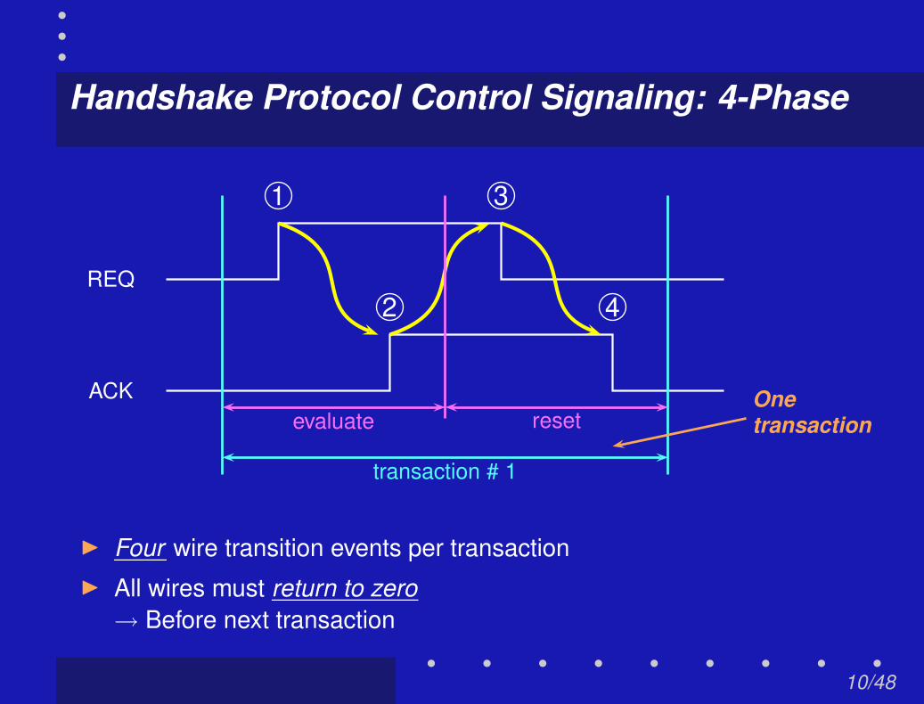
Handshake Protocol Control Signaling: 4-Phase
1
2
3
4REQ
ACK Onetransactionevaluate reset
transaction # 1
I Four wire transition events per transactionI All wires must return to zero
→ Before next transaction
10/48

Handshake Protocol Control Signaling: 2-Phase
1
2
1
2REQ
ACK
transaction #1 transaction #2
Twotransactions
I Two wire transition events per transaction
I No return-to-zero phase
11/48
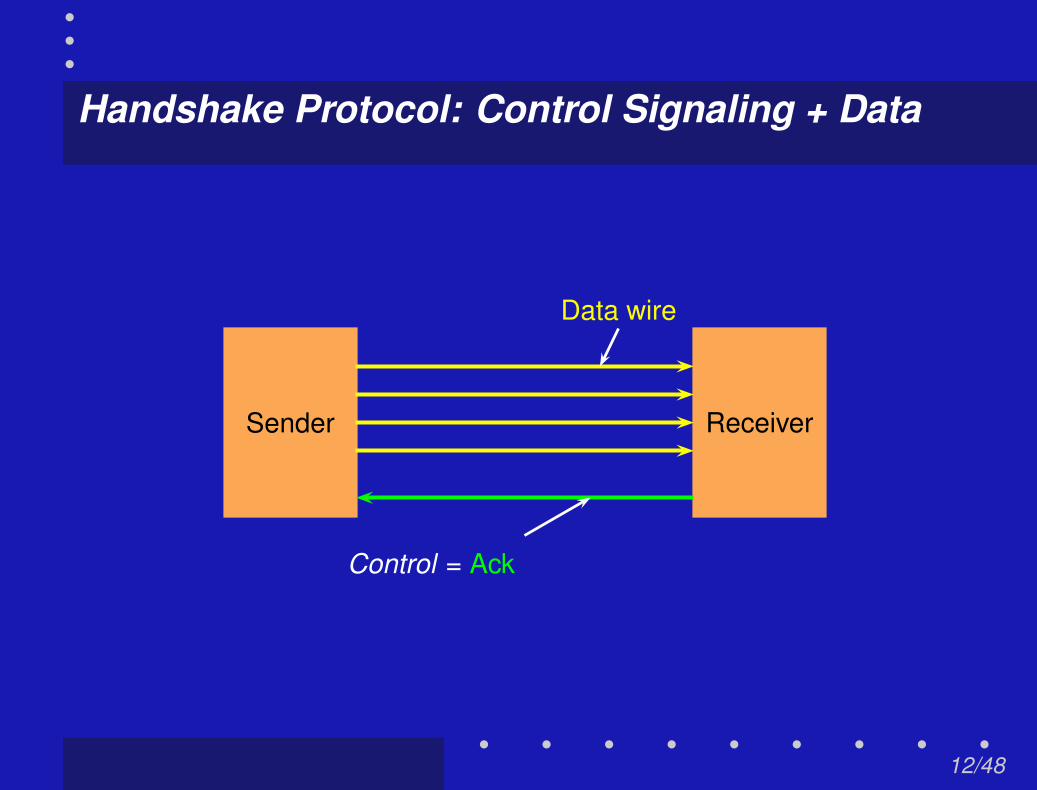
Handshake Protocol: Control Signaling + Data
Sender Receiver
Data wire
Control = Ack
12/48

Handshake Protocol: Control Signaling + Data
Sender Receiver
Data
12/48
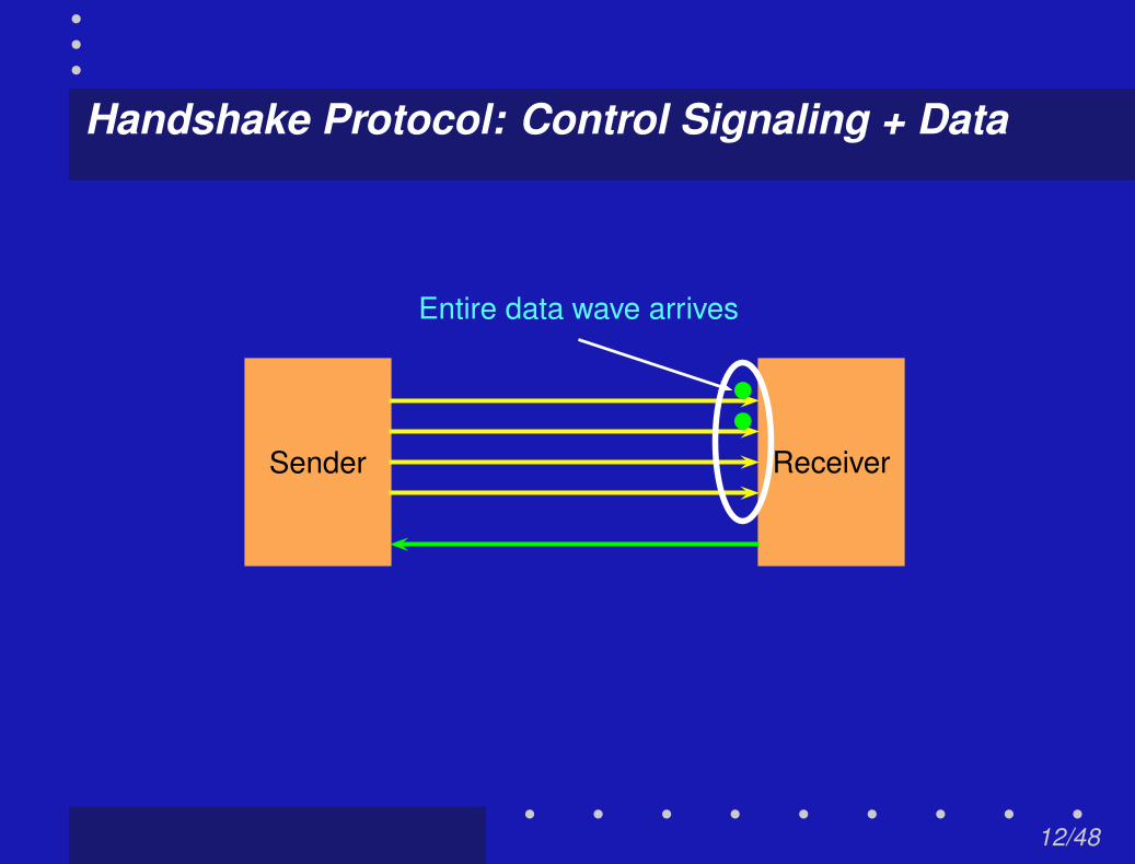
Handshake Protocol: Control Signaling + Data
Sender Receiver
Entire data wave arrives
12/48

Handshake Protocol: Control Signaling + Data
Sender Receiver
Entire data wave arrives
Receiver sends Ack
12/48

Handshake Protocol: Control Signaling + Data
Sender Receiver
Entire data wave arrives
Receiver sends Ack
2-phase transition signaling protocol completes→ Transition signaling = non-return-to-zero (NRZ)
12/48

Handshake Protocol: Control Signaling + Data
Sender Receiver
Spacer tokens (spacer = data reset to zero)
Round trip for 4-phase (return-to-zero) protocol
12/48

Handshake Protocol: Control Signaling + Data
Sender Receiver
All wires reset to zero
Receiver sends Ack
4-phase (return-to-zero) protocol completes
12/48
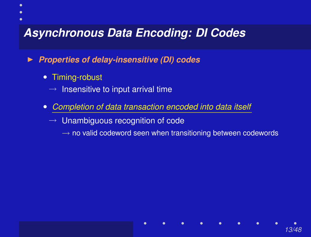
Asynchronous Data Encoding: DI Codes
I Properties of delay-insensitive (DI) codes
• Timing-robust→ Insensitive to input arrival time
• Completion of data transaction encoded into data itself
→ Unambiguous recognition of code→ no valid codeword seen when transitioning between codewords
13/48
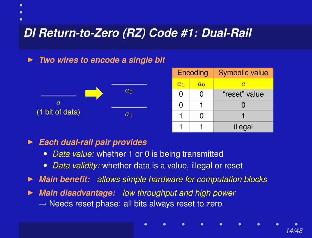
DI Return-to-Zero (RZ) Code #1: Dual-Rail
I Two wires to encode a single bit
a
(1 bit of data) a1
a0
Encoding Symbolic valuea1 a0 a
0 0 “reset” value0 1 01 0 11 1 illegal
I Each dual-rail pair provides• Data value: whether 1 or 0 is being transmitted• Data validity: whether data is a value, illegal or reset
I Main benefit: allows simple hardware for computation blocksI Main disadvantage: low throughput and high power
→ Needs reset phase: all bits always reset to zero
14/48

DI Return-to-Zero (RZ) Code #2: 1-of-N
I N wires to encode log N bits (one-hot encoding)
a
(logN bits of data)
aN−1
a1
a0
Example: 1-of-4 codeEncoding Symbolic value
a3 a2 a1 a0 a
0 0 0 0 “reset" value0 0 0 1 000 0 1 0 010 1 0 0 101 0 0 0 11
All other codewords illegal
I Main benefit: uses lower power than dual-rail→ 1 out of N rails changes value per data transaction
I Main disadvantage: gets expensive beyond 1-of-4→ Coding density decrease→ Complicated to concatenate irregularly-sized data streams
15/48

DI Non-Return-to-Zero (NRZ) Code #1: LEDR
LEDR = Level-Encoded Dual-RailI Two wires to encode a single bit
a
(1 bit of data) parity rail
data rail
Encoding Symbolicvalue
Phase Parity Data a
rail railEven 0 0 0
1 1 1Odd 1 0 0
0 1 1I Properties of LEDR codes:• Level encoded: can retrieve data value directly from wires• Alternating phase protocol: between odd and even phases• Only 1 rail changes value: per bit per data transaction
Dean et al., “Efficient Self-Timing with Level-Encoded 2-Phase Dual-Rail (LEDR)”, Proc.of UCSC Conf. on Adv. Research in VLSI, ’91
16/48
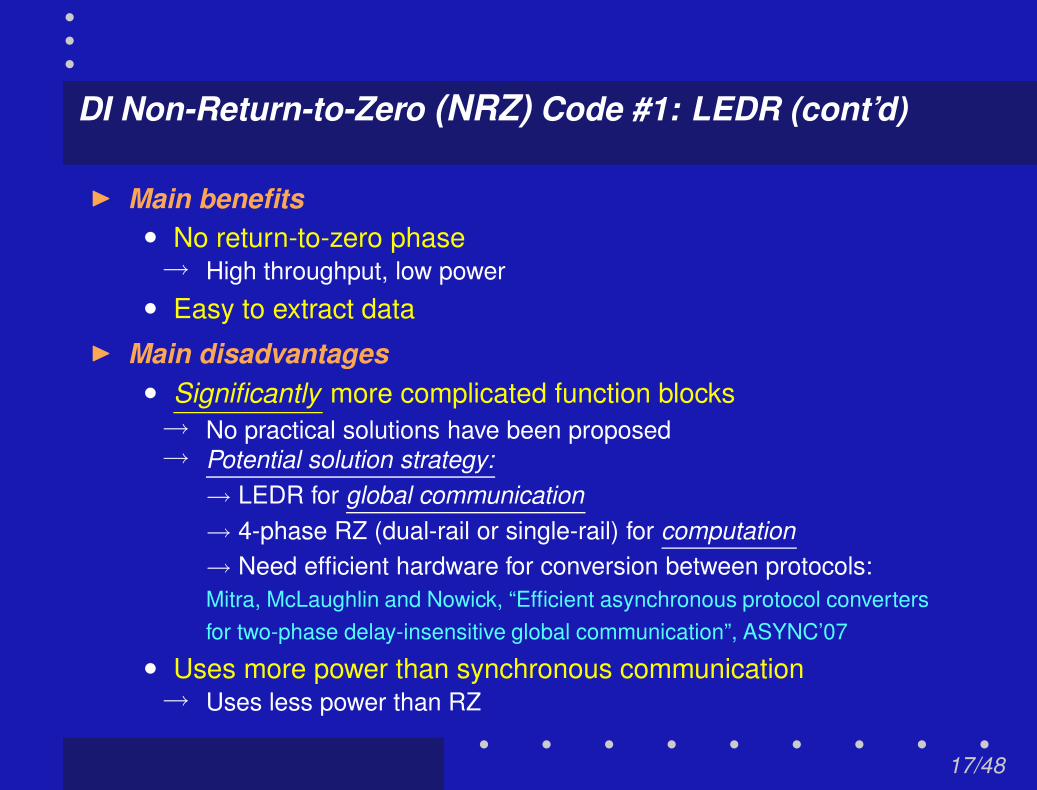
DI Non-Return-to-Zero (NRZ) Code #1: LEDR (cont’d)
I Main benefits• No return-to-zero phase→ High throughput, low power
• Easy to extract dataI Main disadvantages
• Significantly more complicated function blocks→ No practical solutions have been proposed→ Potential solution strategy:
→ LEDR for global communication→ 4-phase RZ (dual-rail or single-rail) for computation→ Need efficient hardware for conversion between protocols:Mitra, McLaughlin and Nowick, “Efficient asynchronous protocol convertersfor two-phase delay-insensitive global communication”, ASYNC’07
• Uses more power than synchronous communication→ Uses less power than RZ
17/48
Outline
I IntroductionI Background
I 1-of-4 LETS codesI 1-of-N LETS codesI Hardware supportI Analytical evaluation
I Conclusions
18/48

LETS Codes: Motivation & Contributions
“LETS = Level-Encoded Transition Signaling”I A new class of delay-insensitive codes
• Extension of LEDR = 1-of-2 LETS→ Uses fewer wire transitions per data transaction→ Analogous to 1-of-N extension to dual-rail in RZ
• Goal:→ Generate and evaluate entire family of 1-of-N codes
I Key benefits• Maintains benefits of LEDR→ High throughput→ Delay-insensitive→ Efficient hardware conversion to 4-phase protocols
• Additional benefit→ Lower power consumption than LEDR
19/48

1-of-4 LETS Code Derivation: Overview
w=0
w=1
x
yz
Starting point: 4-bit code space
Code space represented by 4-D hypercube
16 codewords in code space
20/48

1-of-4 LETS Code Derivation: Overview
w=0
w=1
x
yz
→ such that all LETS properties are observed
Goal: assign symbols to codewords→ Symbols to assign = {S0, S1, S2, S3}→ Codewords = {0000, 0001, ...., 1111}
20/48

1-of-4 LETS Code Derivation: Overview
w=0
w=1
x
yz
Goal: assign symbols to codewords→ Symbols to assign = {S0, S1, S2, S3}→ Codewords = {0000, 0001, ...., 1111}
Rule 2 (Reachability):→ Each symbol Sx must reach all symbols S0 − S3 in opposite phase
Rule 1 (Alternating phases):→ Odd and even phases must alternate
20/48

1-of-4 LETS Code Derivation: Details
w=0
w=1
x
yz
S0
Step 1: assign arbitrary symbol to arbitrary codeword
0000
EVEN phase
21/48

1-of-4 LETS Code Derivation: Details
w=0
w=1
x
yz
S0
S0S2
S3
S1
Step 2: assign symbols to all neighbors of S0 at 0000 in ODD phase
Rule 1 (Reachability):→ Each symbol Sx must reach all symbols S0 − S3 in opposite phase
ODD phase
21/48

1-of-4 LETS Code Derivation: Details
w=0
w=1
x
yz
S0
S0S2
S3
S1
EVEN phase
Step 3: assign symbols to all neighbors of S1 at 1000 in EVEN phase
Assign neighbors to S1
21/48

1-of-4 LETS Code Derivation: Details
w=0
w=1
x
yz
S0
S0S2
S3
S1
EVEN phase
Step 3: assign symbols to all neighbors of S1 at 1000 in EVEN phase
S0 already assigned to 0000
21/48

1-of-4 LETS Code Derivation: Details
w=0
w=1
x
yz
S0
S0S2
S3
S1
S2’S1’
S3’
EVEN phase
Step 3: assign symbols to all neighbors of S1 at 1000 in EVEN phase
Assign S1, S2 and S3 to remaining neighbors
21/48

1-of-4 LETS Code Derivation: Details
w=0
w=1
x
yz
S0
S0S2
S3
S1
S2’S1’
S3’
S1’
S3’
S2’
S0’
S3
S1
S2
S0’Final steps: complete symbol assignment
Follow same reasoning in previous steps
21/48

1-of-4 LETS Code Derivation: Summary
w=0
w=1
x
yz
S0
S0S2
S3
S1
S2’S1’
S3’
S1’
S3’
S2’
S0’
S3
S1
S2
S0’
Code space divided into EVEN and ODD phases
Entire code space filled up
Codewords in even phase
Codewords in odd phase
22/48
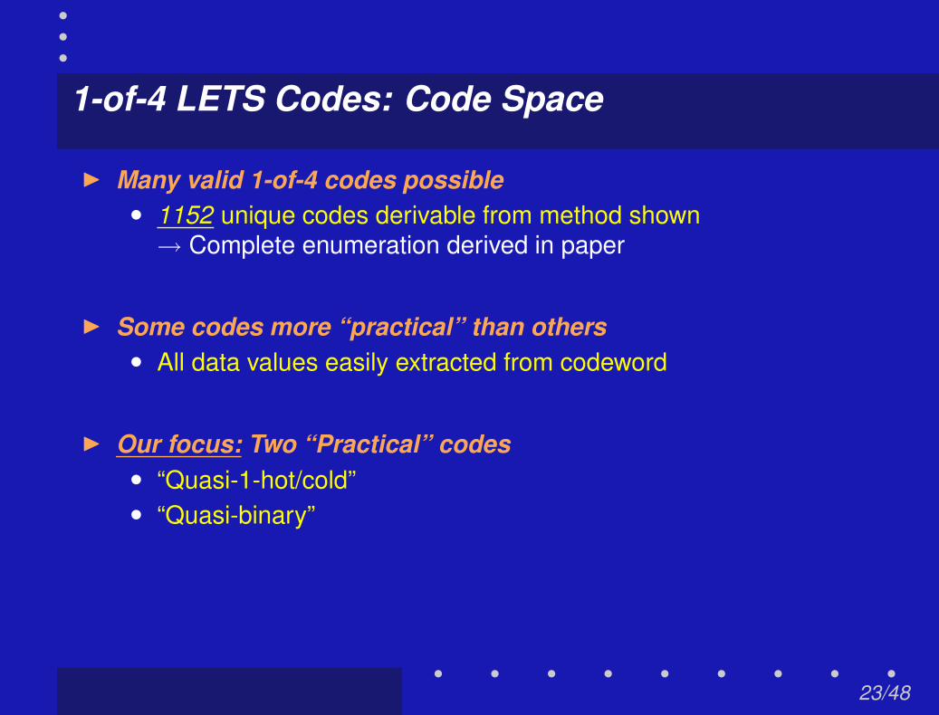
1-of-4 LETS Codes: Code Space
I Many valid 1-of-4 codes possible• 1152 unique codes derivable from method shown
→ Complete enumeration derived in paper
I Some codes more “practical” than others• All data values easily extracted from codeword
I Our focus: Two “Practical” codes• “Quasi-1-hot/cold”• “Quasi-binary”
23/48

A Practical 1-of-4 LETS Code: “Quasi-1-Hot/Cold"
symbol r3 r2 r1 r0
S0 1 0 0 0S1 0 1 0 0S2 0 0 1 0S3 0 0 0 1
S0 1 1 1 1S1 0 0 1 1S2 0 1 0 1S3 0 1 1 0
symbol r3 r2 r1 r0
S0’ 0 1 1 1S1’ 1 0 1 1S2’ 1 1 0 1S3’ 1 1 1 0
S0’ 0 0 0 0S1’ 1 1 0 0S2’ 1 0 1 0S3’ 1 0 0 1
16 codewords for 4 symbols
24/48

A Practical 1-of-4 LETS Code: “Quasi-1-Hot/Cold"
symbol r3 r2 r1 r0
S0 1 0 0 0S1 0 1 0 0S2 0 0 1 0S3 0 0 0 1
S0 1 1 1 1S1 0 0 1 1S2 0 1 0 1S3 0 1 1 0
symbol r3 r2 r1 r0
S0’ 0 1 1 1S1’ 1 0 1 1S2’ 1 1 0 1S3’ 1 1 1 0
S0’ 0 0 0 0S1’ 1 1 0 0S2’ 1 0 1 0S3’ 1 0 0 1
ODDcode-words
EVENcode-words
Code space divided into ODD and EVEN phases
24/48

A Practical 1-of-4 LETS Code: “Quasi-1-Hot/Cold"
symbol r3 r2 r1 r0
S0 1 0 0 0S1 0 1 0 0S2 0 0 1 0S3 0 0 0 1
S0 1 1 1 1S1 0 0 1 1S2 0 1 0 1S3 0 1 1 0
symbol r3 r2 r1 r0
S0’ 0 1 1 1S1’ 1 0 1 1S2’ 1 1 0 1S3’ 1 1 1 0
S0’ 0 0 0 0S1’ 1 1 0 0S2’ 1 0 1 0S3’ 1 0 0 1
ODDcode-words
EVENcode-words
Multicode: 2 codewords for each symbol in each phase
24/48
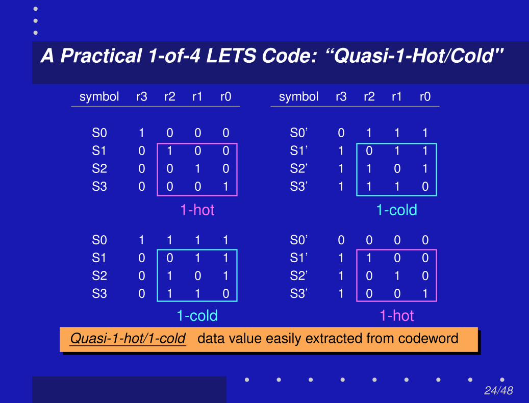
A Practical 1-of-4 LETS Code: “Quasi-1-Hot/Cold"
symbol r3 r2 r1 r0
S0 1 0 0 0S1 0 1 0 0S2 0 0 1 0S3 0 0 0 1
S0 1 1 1 1S1 0 0 1 1S2 0 1 0 1S3 0 1 1 0
symbol r3 r2 r1 r0
S0’ 0 1 1 1S1’ 1 0 1 1S2’ 1 1 0 1S3’ 1 1 1 0
S0’ 0 0 0 0S1’ 1 1 0 0S2’ 1 0 1 0S3’ 1 0 0 1
1-hot 1-cold
1-cold 1-hotQuasi-1-hot/1-cold data value easily extracted from codeword
24/48

Outline
I IntroductionI Background
I 1-of-4 LETS codesI 1-of-N LETS codesI Hardware supportI Analytical evaluation
I Conclusions
25/48

1-of-N LETS Codes
I Goal• To extend solution for 1-of-4 LETS codes to 1-of-N
I Challenge:• Solution is not obvious for arbitrary N• Must satisfy several properties
→ Level-encoding: data can be extracted directly from codeword→ Transition signaling: each symbol must reach all others via 1 flip
→ alternating phase
I Contributions• Proof: existence of legal LETS codes for every N = 2n
• Systematic procedure to generate LETS codes→ LETS properties formulated as set of constraints→ Constraints captured in code generator matrix→ Many different LETS codes exist for each N
See paper for details
26/48

Outline
I IntroductionI Background
I 1-of-4 LETS codesI 1-of-N LETS codesI Hardware support
• Conversion circuit: interfacing channels to nodes• LETS pipeline circuit: improving channel throughput
I Analytical evaluation
I Conclusions
27/48

LETS Hardware Support: Protocol Conversion
Computationnode
Asynchronous4-phase RZ
Computationnode
Asynchronous4-phase RZ
Dataencode
ordecode
Dataencode
ordecodeAsynchronous
communication channel(LETS)
First, focus on protocol conversion circuits
28/48
LEDR Converter: Prior Architecture Overview
fourphase
functionblock
fourphaseencode
fourphasedecode
data
parity
LEDRCD
data
parity
LEDRCD
control logic
2-phasecomm.channel
2-phasecomm.channel
LEDR Converter from Mitra et al., "Efficient Asynchronous Protocol Convertersfor Two-Phase Delay-Insensitive Global Communication", ASYNC’07
29/48

LEDR Converter: Prior Architecture Overview
fourphase
functionblock
fourphaseencode
fourphasedecode
data
parity
LEDRCD
data
parity
LEDRCD
control logic
2-phasecomm.channel
2-phasecomm.channel
2/4-phase conversion circuit
2-phasecompletiondetector
2-phasecompletiondetector
29/48

LEDR Converter: Control Signals
two phase signals
four phase signals
fourphase
functionblock
fourphaseencode
fourphasedecode
data
parity
LEDRCD
data
parity
LEDRCD
control logic
LEDR input LEDR output
ack_left ack_right
phase
phase
enb comp
30/48

New contribution: 1-of-4 LETS Converter
I Based on existing LEDR (1-of-2 LETS) converter
• Only minor modifications needed
→ Same overall architecture
→ Most pieces identical
→ Internal logic of some blocks have minimal changes
31/48

1-of-4 LETS Converter
fourphase
functionblock
fourphaseencode
fourphasedecode
data
parity
LEDRCD
data
parity
LEDRCD
control logic
LEDR input LEDR output
ack_left ack_right
phase
phase
enb comp
= Changed logic blocks
32/48

Completion Detector: LEDR vs. 1-of-4 LETS
completion detector
C
C
C
C
C
C
C
C
LEDR completion detector 1-of-4 LETS completion detector
One layer of C-elements replaced by XNOR gates
33/48

Left Encoder: LEDR vs. 1-of-4 LETS
left encoder
Enable
Enable
4−phasetrue rail b0
false rail b04−phase
true rail b14−phase
4−phasefalse rail b1
data bit b1LEDR
data bit b0LEDR
Enable
Enable
4−phasetrue rail b0
4−phasefalse rail b0
4−phasetrue rail b1
false rail b14−phase
LETSdata_r0
data_r1LETS
LETSdata_r0
data_r2LETS
LEDR left encoder 1-of-4 LETS left encoder
Extra layer of XNOR gatesI Not on critical path!
34/48

Right Encoder: LEDR vs. 1-of-4 LETS
right encoder
Inputphase LEDR
parityrail b0
LEDRdata
rail b0
parityLEDR
rail b1
LEDRdata
rail b1
S
R
Q
SQ
R
G
Q
S
R
Q
SQ
D
R
complete
4−phase true rail b04−phase false rail b0
4−phase true rail b14−phase false rail b1
S
R
S
R
S
R
S
R
STORAGE COMPARATOR
r3
r1
r0
r2
r0
r1
r3
r0
r1
r2
r3
SELECT
z2
z1
z3
z0
r2
r2r1
r0
r3
true
b1
φφφ φcompleteenable
z3
z2
z1
z0
LETSOUTPUTS
fals
e b1
true
b0
fals
e b0
4444
Q’
QD
Q’
QD
Q’
QD
Q’
QD
LEDR right encoder 1-of-4 LETS right encoder
Extra storage logicI Not on critical path!
select block
35/48

1-of-4 LETS Converter Performance Evaluation
I Layout performed for LEDR (1-of-2 LETS) conversion circuitsMitra et al., "Efficient Asynchronous Protocol Converters for Two-Phase Delay-Insensitive
Global Communication", ASYNC’07
• With a 4-phase multiplier function block• 0.18µm TSMC CMOS process• Summary of simulation results:
Forward latency input arrival → output data available 6.8nsStabilization time input arrival → reset complete 10.5nsPipelined cycle time min processing time / data item (steady state) 8.3ns
I 1-of-4 LETS expected to add 15 - 20% overheadI Design is delay-insensitive
→ Except for two simple one-sided timing constraints
36/48

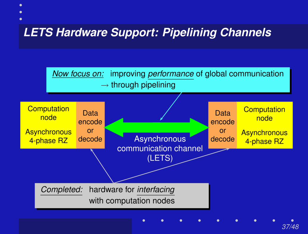
LETS Hardware Support: Pipelining Channels
Computationnode
Asynchronous4-phase RZ
Computationnode
Asynchronous4-phase RZ
Dataencode
ordecode
Dataencode
ordecodeAsynchronous
communication channel(LETS)
Completed: hardware for interfacingwith computation nodes
37/48
LETS Hardware Support: Pipelining Channels
Computationnode
Asynchronous4-phase RZ
Computationnode
Asynchronous4-phase RZ
Dataencode
ordecode
Dataencode
ordecodeAsynchronous
communication channel(LETS)
Completed: hardware for interfacingwith computation nodes
Now focus on: improving performance of global communication→ through pipelining
37/48
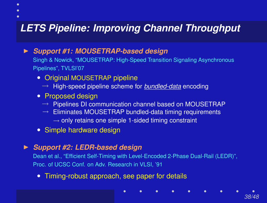
LETS Pipeline: Improving Channel Throughput
I Support #1: MOUSETRAP-based designSingh & Nowick, “MOUSETRAP: High-Speed Transition Signaling AsynchronousPipelines”, TVLSI’07
• Original MOUSETRAP pipeline→ High-speed pipeline scheme for bundled-data encoding
• Proposed design→ Pipelines DI communication channel based on MOUSETRAP→ Eliminates MOUSETRAP bundled-data timing requirements
→ only retains one simple 1-sided timing constraint• Simple hardware design
I Support #2: LEDR-based designDean et al., “Efficient Self-Timing with Level-Encoded 2-Phase Dual-Rail (LEDR)”,Proc. of UCSC Conf. on Adv. Research in VLSI, ’91
• Timing-robust approach, see paper for details
38/48
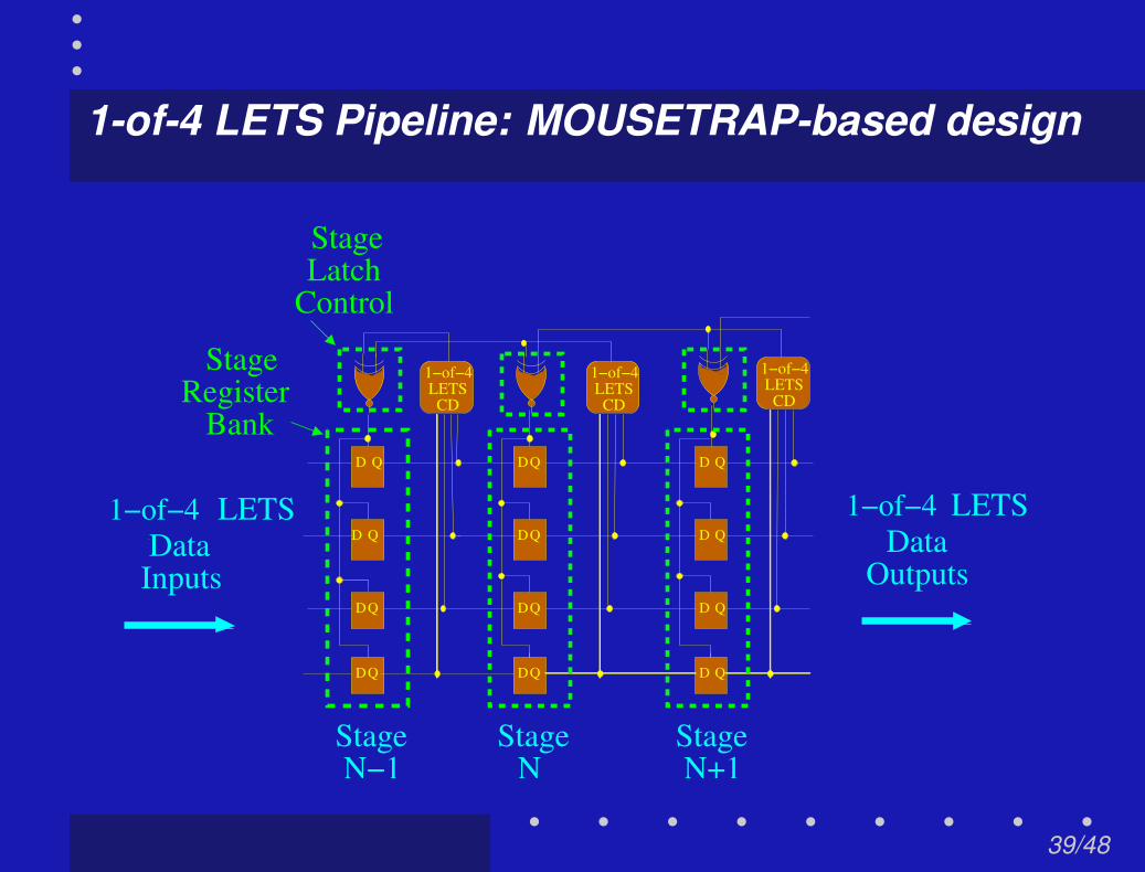
1-of-4 LETS Pipeline: MOUSETRAP-based design
StageN−1
StageN
Bank
Control
N+1Stage
1−of−4 1−of−4
CDLETS
1−of−4LETS
CDLETS
CD
StageRegister
StageLatch
1−of−4DataInputs
1−of−4Data
Outputs
LETS LETS
D
D
D
D
Q
Q
Q
QQD
D
D
D
Q
Q
Q
D
D
D
D
Q
Q
Q
Q
39/48

1-of-4 LETS Pipeline: MOUSETRAP-based design
StageN−1
StageN
Bank
Control
N+1Stage
1−of−4 1−of−4
CDLETS
1−of−4LETS
CDLETS
CD
StageRegister
StageLatch
1−of−4DataInputs
1−of−4Data
Outputs
LETS LETS
D
D
D
D
Q
Q
Q
QQD
D
D
D
Q
Q
Q
D
D
D
D
Q
Q
Q
Q
Latch control:→ same as MOUSTRAP
Completion detector:→ replaced with 1-of-4 LETS CD
39/48

Outline
I IntroductionI Background
I 1-of-4 LETS codesI 1-of-N LETS codesI Hardware supportI Analytical evaluation
• Coding efficiency and transition power metric
I Conclusions
40/48

Analytical Evaluation: Coding Efficiency (LETS vs. RZ)
0
1/10
1/5
3/10
2/5
1/2
3/5
RZLETS
bits/rails
1 of N LETS vs. 1 of N RZ
# of Rails
2 4 8 16 32 64 128 264
Coding Efficiency
1-of-N LETS vs. RZ codesI Same coding efficiency
41/48

Analytical Evaluation: Coding Efficiency (LETS vs. RZ)
0
1/10
1/5
3/10
2/5
1/2
3/5
RZLETS
bits/rails
1 of N LETS vs. 1 of N RZ
# of Rails
2 4 8 16 32 64 128 264
Coding Efficiency
1-of-N LETS vs. RZ codesI Same coding efficiency
Coding efficiency drops off after N>4
41/48

Analytical Evaluation: Transition Power (LETS vs. RZ)
0
1/2
1
1 1/2
2
2 1/2
LETS
RZ
wire flips/transaction
1 of N LETS vs. 1 of N RZ
Transition Power
# of Rails
2 4 8 16 32 64 128 264
1-of-N LETS vs. RZ codesI LETS uses less power
42/48

Analytical Evaluation: Interpreting LETS Scaling
0
1/5
2/5
3/5
4/5
1
1 1/5
Transition Power
Coding Efficiency
wire flips/transaction
bits/rails
1 of N LETS
Transition Power and Coding Efficiency
# of Rails
2 4 8 16 32 64 128 264
43/48

Analytical Evaluation: Interpreting LETS Scaling
0
1/5
2/5
3/5
4/5
1
1 1/5
Transition Power
Coding Efficiency
wire flips/transaction
bits/rails
1 of N LETS
Transition Power and Coding Efficiency
# of Rails
2 4 8 16 32 64 128 264
Trend: Power decreases as # of rails increase→ but coding efficiency also decreases
Sweet spot: going from LEDR to 1-of-4 LETS→ halves the power, same coding efficiency
43/48

Analytical Evaluation: LETS vs. Synchronous
I Coding efficiency (# bits encoded/wire)
• Synchronous better than 1-of-N LETS→ Synchronous: N bits for N wires→ 1-of-N LETS: log N bits for N wires
I Transition power metric (# transitions/wire/data transaction)
• 1-of-N LETS better than synchronous as N increases→ Synchronous: constant
→ assumes equal probability of wire transition→ 1-of-N LETS: decreases as N grows
→ = 1 / log N→ Transition power metric same for N = 4
44/48

Conclusions
I A new class of delay-insensitive codes“Level-Encoded Transition Signaling (LETS)”• High throughput, low power for global communication• Two example 1-of-4 LETS codes shown• Generalization to 1-of-N LETS
→ first 1-of-N level-encoded transition signaling scheme
I Efficient hardware• For protocol conversion to/from four-phase dual-rail signaling• For pipelining global communication channel
I Power and throughput improvements over existing codes• Demonstrated via analytical evaluation
45/48

Future Work
I Better evaluation of performance/power metrics
• Layout of proposed circuits• Evaluation of second-order effects
→ e.g. cross-coupling, noise, etc
I Extend conversion circuits to support other encoding styles
• e.g. 1-of-4 RZ, single-rail bundled
46/48

Appendix
47/48

LEDR Converter: System Simulation
fourphase
functionblock
fourphaseencode
fourphase
decode
data
parity
LEDRCD
data
parity
LEDRCD
control logic
LEDR input LEDR output
ack_left ack_right
phase
phase
enb comp
completiondetection
LEDRInputsarrive
Step 1: Two-phase inputs arriveLEDR inputs begin arriving at quiescent system
48/48

LEDR Converter: System Simulation
fourphase
functionblock
fourphaseencode
fourphase
decode
data
parity
LEDRCD
data
parity
LEDRCD
control logic
LEDR input LEDR output
ack_left ack_right
phase
phase
enb comp
Phasesignalchanges
Step 2: Two-to-four phase conversion
Input completion detection sent to control
48/48
LEDR Converter: System Simulation
fourphase
functionblock
fourphaseencode
fourphase
decode
data
parity
LEDRCD
data
parity
LEDRCD
control logic
LEDR input LEDR output
ack_left ack_right
phase
phase
enb comp
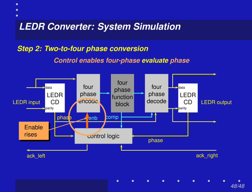
Enablerises
Step 2: Two-to-four phase conversion
Control enables four-phase evaluate phase
48/48

LEDR Converter: System Simulation
fourphase
functionblock
fourphaseencode
fourphase
decode
data
parity
LEDRCD
data
parity
LEDRCD
control logic
LEDR input LEDR output
ack_left ack_right
phase
phase
enb comp
Enablenow high
Step 2: Two-to-four phase conversion
LEDR input converted to four-phase
48/48

LEDR Converter: System Simulation
fourphase
functionblock
fourphaseencode
fourphase
decode
data
parity
LEDRCD
data
parity
LEDRCD
control logic
LEDR input LEDR output
ack_left ack_right
phase
phase
enb comp
Step 3: Four-phase evaluate
Four-phase function evaluation
48/48

LEDR Converter: System Simulation
fourphase
functionblock
fourphaseencode
fourphase
decode
data
parity
LEDRCD
data
parity
LEDRCD
control logic
LEDR input LEDR output
ack_left ack_right
phase
phase
enb comp
LEDR outputgenerated
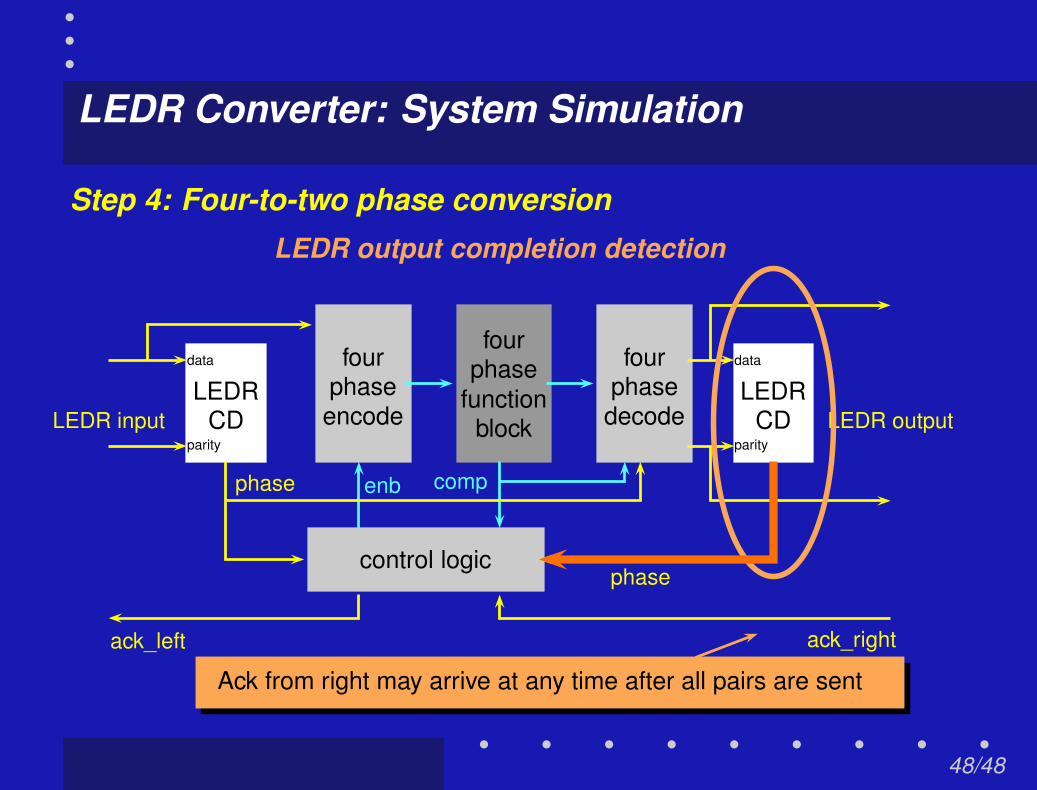
Step 4: Four-to-two phase conversion
Four-phase bits decoded to LEDR
48/48
LEDR Converter: System Simulation
fourphase
functionblock
fourphaseencode
fourphase
decode
data
parity
LEDRCD
data
parity
LEDRCD
control logic
LEDR input LEDR output
ack_left ack_right
phase
phase
enb comp
Ack from right may arrive at any time after all pairs are sent
Step 4: Four-to-two phase conversion
LEDR output completion detection
48/48

LEDR Converter: System Simulation
fourphase
functionblock
fourphaseencode
fourphase
decode
data
parity
LEDRCD
data
parity
LEDRCD
control logic
LEDR input LEDR output
ack_left ack_right
phase
phase
enb comp
Enablefalls
Step 5: Four-phase reset
Control enables four-phase reset phase
48/48

LEDR Converter: System Simulation
fourphase
functionblock
fourphaseencode
fourphase
decode
data
parity
LEDRCD
data
parity
LEDRCD
control logic
LEDR input LEDR output
ack_left ack_right
phase
phase
enb comp
Enablenow low
Pipeline concurrency:Request new data during reset
Step 5: Four-phase reset
Function block inputs return to zero
48/48
LEDR Converter: System Simulation
fourphase
functionblock
fourphaseencode
fourphase
decode
data
parity
LEDRCD
data
parity
LEDRCD
control logic
LEDR input LEDR output
ack_left ack_right
phase
phase
enb comp
Complete falls
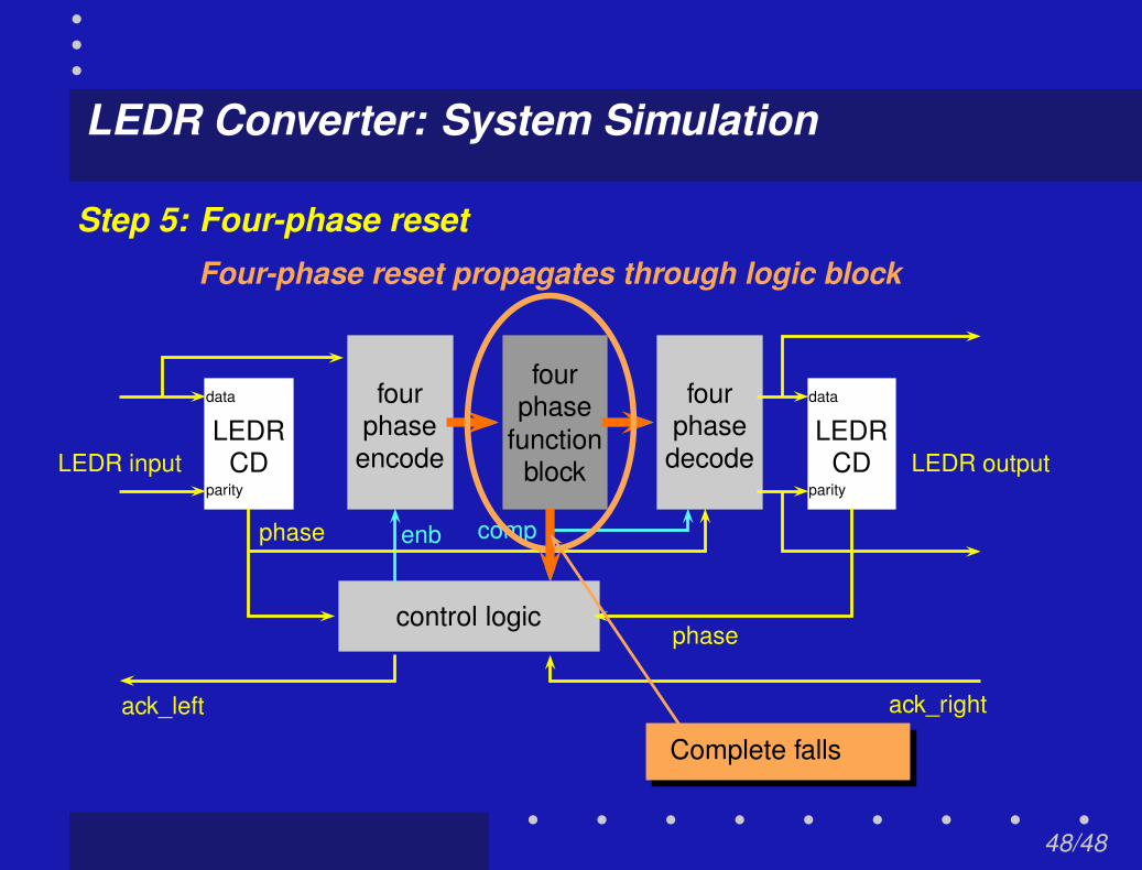
Step 5: Four-phase resetFour-phase reset propagates through logic block
48/48

LEDR Converter: System Simulation
fourphase
functionblock
fourphaseencode
fourphase
decode
data
parity
LEDRCD
data
parity
LEDRCD
control logic
LEDR input LEDR output
ack_left ack_right
phase
phase
enb comp
Ready to evaluate againNew evaluate phase begins when enable rises again
48/48