A Lego Mindstorms NXT Experiment for Model Predictive...
6
A Lego Mindstorms NXT experiment for Model Predictive Control education Massimo Canale Dipartimento di Automatica e Informatica Politecnico di Torino Italy [email protected] Simone Casale Brunet SCI-STI-MM ´ Ecole Polytechnique F´ ed´ erale de Lausanne Switzerland [email protected] Abstract— This paper presents an educational framework based on the Lego Mindstorms NXT robotic platform used to outline both the theoretical and practical aspects of the Model Predictive Control theory. The case of a two-wheeled inverted pendulum is considered as at-size scenario. For such a system, starting from its mathematical modeling, an established design methodology is presented aiming to outline step-by-step the predictive controller implementation on a low-power ar- chitecture. The effectiveness of this multidisciplinary approach is illustrated along this presentation and demonstrated with experimental results. I. I NTRODUCTION Model Predictive Control (MPC) [1] has been established as an effective methodology for a wide range of applications in different engineering fields (see e.g. [2]) due to its effi- ciency in constraints handling and performance achievement. As a matter of fact, since in MPC the control action is computed, for each sampling time, through the solution to an optimization problem, its use has been restricted, for several years, to plants with slow dynamics (e.g. petrochemical, biomedical). Indeed, thanks to the efficient implementation strategies recently developed, the successful employment of MPC has been extended to applications whose sampling times prevented online solution to the optimization prob- lem. In such a context, several methodologies have been proposed in order to compute the control move at a given sampling time (see e.g. [3]–[8] and the references therein). Among these solutions, the use of an approximate control law obtained through the off-line computation of a finite number of values of the actual controller (see e.g. [3], [5], [9]) has shown to be quite effective in the control of nonlinear complex plants as introduced, e.g., in [10], [11]. It is worth noting that, when an approximate MPC controller is used, the actual performance of the controlled system relies on an effective development of several design steps. In particular, a complete design procedure needs, besides a suitable choice of the problem formulation (i.e. plant modeling, cost function, constraints, ...), the computation of the values of the nominal controller in order to perform the control law approximation, realistic simulations of the controlled plant performed through the MatLab/Simulink environment to effectively test the system in the presence of the approximate controller and, finally, an effective soft- ware implementation on the available hardware platform. Therefore, a successful realization of an MPC controller requires a certain expertise in all the above described steps of the design procedure. On the basis of the considerations above, improvements in the practice of MPC can be achieved by introducing in the related education, suitable didactic at-size experimental scenarios which take care of all the aspects involved in the design ranging from modeling to real time implementation of the controller. In this contribution, we describe the deployment of an experimental framework well suited for educational purposes in which all the design steps previously introduced are considered. In particular, the problem of design and implementation of an MPC controller for an inverted pendulum built with the didactic environment Lego Mindstorm NXT will be described. Such a platform has been chosen, since, due to its low cost and versatility in building challenging laboratory experiments, it has been widely employed for control education purposes (see e.g. [12], [13]). Another interesting feature of the Lego Mindstorm NXT is that it supports, among others, the open source environment nxtOSEK which includes a real time operating system (i.e. TOPPER/JSP) and it can be easily interfaced with a desktop computer running MatLab allowing, in such a way, the deployment of the source code for the implementation of the MPC controller. The paper is organized as follows: in Section II the main features of the employed Lego Mindstorm NXT are described; the modeling and the MPC control design procedures are intro- duced in Sections III and IV respectively, while, in Section V controller verification and validation procedures as well as the obtained experimental results are presented. Some concluding remarks end the paper. II. THE LEGO MINDSTORM PLATFORM A two wheeled inverted pendulum has been used as at-size scenario, since practical use case studies have been proved to be more productively in the long term [14], [15]. This has been implemented with the low cost and widely used Lego Mindstorms NXT robotic kit. This is an educational platform representing the evolution of six decades of mod- ular construction techniques from Lego and with years of computer-based education methods [16]. Using this robotic platform several different at-size scenarios can be easily arranged [12]–[14]. Indeed, the choice of a two wheeled inverted pendulum has been oriented by the challenging goal of controlling a plant with fast dynamics around an 2013 European Control Conference (ECC) July 17-19, 2013, Zürich, Switzerland. 978-3-952-41734-8/©2013 EUCA 2549
Transcript of A Lego Mindstorms NXT Experiment for Model Predictive...

A Lego Mindstorms NXT experimentfor Model Predictive Control education
Massimo CanaleDipartimento di Automatica e Informatica
Politecnico di TorinoItaly
Simone Casale BrunetSCI-STI-MM
Ecole Polytechnique Federale de LausanneSwitzerland
Abstract— This paper presents an educational frameworkbased on the Lego Mindstorms NXT robotic platform usedto outline both the theoretical and practical aspects of theModel Predictive Control theory. The case of a two-wheeledinverted pendulum is considered as at-size scenario. For such asystem, starting from its mathematical modeling, an establisheddesign methodology is presented aiming to outline step-by-stepthe predictive controller implementation on a low-power ar-chitecture. The effectiveness of this multidisciplinary approachis illustrated along this presentation and demonstrated withexperimental results.
I. INTRODUCTION
Model Predictive Control (MPC) [1] has been establishedas an effective methodology for a wide range of applicationsin different engineering fields (see e.g. [2]) due to its effi-ciency in constraints handling and performance achievement.As a matter of fact, since in MPC the control action iscomputed, for each sampling time, through the solution to anoptimization problem, its use has been restricted, for severalyears, to plants with slow dynamics (e.g. petrochemical,biomedical). Indeed, thanks to the efficient implementationstrategies recently developed, the successful employment ofMPC has been extended to applications whose samplingtimes prevented online solution to the optimization prob-lem. In such a context, several methodologies have beenproposed in order to compute the control move at a givensampling time (see e.g. [3]–[8] and the references therein).Among these solutions, the use of an approximate controllaw obtained through the off-line computation of a finitenumber of values of the actual controller (see e.g. [3],[5], [9]) has shown to be quite effective in the control ofnonlinear complex plants as introduced, e.g., in [10], [11]. Itis worth noting that, when an approximate MPC controlleris used, the actual performance of the controlled systemrelies on an effective development of several design steps.In particular, a complete design procedure needs, besidesa suitable choice of the problem formulation (i.e. plantmodeling, cost function, constraints, ...), the computation ofthe values of the nominal controller in order to performthe control law approximation, realistic simulations of thecontrolled plant performed through the MatLab/Simulinkenvironment to effectively test the system in the presenceof the approximate controller and, finally, an effective soft-ware implementation on the available hardware platform.Therefore, a successful realization of an MPC controller
requires a certain expertise in all the above described stepsof the design procedure. On the basis of the considerationsabove, improvements in the practice of MPC can be achievedby introducing in the related education, suitable didacticat-size experimental scenarios which take care of all theaspects involved in the design ranging from modeling to realtime implementation of the controller. In this contribution,we describe the deployment of an experimental frameworkwell suited for educational purposes in which all the designsteps previously introduced are considered. In particular,the problem of design and implementation of an MPCcontroller for an inverted pendulum built with the didacticenvironment Lego Mindstorm NXT will be described. Sucha platform has been chosen, since, due to its low cost andversatility in building challenging laboratory experiments, ithas been widely employed for control education purposes(see e.g. [12], [13]). Another interesting feature of theLego Mindstorm NXT is that it supports, among others,the open source environment nxtOSEK which includes areal time operating system (i.e. TOPPER/JSP) and it can beeasily interfaced with a desktop computer running MatLaballowing, in such a way, the deployment of the source codefor the implementation of the MPC controller. The paperis organized as follows: in Section II the main featuresof the employed Lego Mindstorm NXT are described; themodeling and the MPC control design procedures are intro-duced in Sections III and IV respectively, while, in SectionV controller verification and validation procedures as wellas the obtained experimental results are presented. Someconcluding remarks end the paper.
II. THE LEGO MINDSTORM PLATFORM
A two wheeled inverted pendulum has been used as at-sizescenario, since practical use case studies have been provedto be more productively in the long term [14], [15]. Thishas been implemented with the low cost and widely usedLego Mindstorms NXT robotic kit. This is an educationalplatform representing the evolution of six decades of mod-ular construction techniques from Lego and with years ofcomputer-based education methods [16]. Using this roboticplatform several different at-size scenarios can be easilyarranged [12]–[14]. Indeed, the choice of a two wheeledinverted pendulum has been oriented by the challenginggoal of controlling a plant with fast dynamics around an
2013 European Control Conference (ECC)July 17-19, 2013, Zürich, Switzerland.
978-3-952-41734-8/©2013 EUCA 2549

unstable equilibrium point. In the following, the main LegoMindstorms NXT environment features are outlined.
A. Hardware capability and limitation
According to [17], [18], the Lego Mindstorms NXTsystem architecture is summarized in Fig. 1. The NXTIntelligent Brick is the heart of the system and containsthe main computational units and communication interfacesused by sensors and actuators. Two processors are used: a32-bit ARM7TDMI (48 MHz, 256 KB flash memory, 64KB RAM) used as main processor and a 8-bit ATmega48micro-controller (4 MHz, 4 KB flash memory, 512 BytesRAM) used as servo driver. Moreover, the Intelligent Brickhas three motor driver ports with encoder inputs and foursensor inputs I2C-capable with two digital I/O lines and oneanalog input. Both wired (i.e. I2C, USB 1.1 slave mode andR485) and wireless (Bluetooth) communication interfaces aresupported for external devices communication. Different kindof manufactured sensors are provided by Lego (e.g. colorsensor, touch sensor, light sensor, ultrasonic sensors) and bythird party commercial suppliers as well (e.g. accelerometersensor, gyrosensor, compass sensor).
Main ProcessorATMEL ARM7
AT91SAM7S256
Co-ProcessorATMEL AVR
ATmega48/V
I2C
A/D PWM
Pulses
USB/BluetoothRS485
I2C
Fig. 1: The Lego Mindstorms NXT platform architecture
B. Software capability and limitation
The Intelligent Brick configuration supports both NXT-Gand LabVIEW programming languages, although a varietyof similar unofficial languages exist such as NXC, NBC,leJOS NXJ, and RobotC. On the other hand, from theauthors’ experience, the nxtOSEK [19] seems to be a suitablecandidate for a first programming approach towards real timesystems due to the characteristics described hereafter. Thisis an open-source environment that consists of device driverof leJOS NXJ C/Assembly source code, the TOPPERS/ATK(Automotive Kernel, formerly known as TOPPERS/OSEK)and the TOPPERS/JSP Real-Time Operating System. More-over, it fulfills the OSEK/VDX standards, widely used in theautomotive domains, it provides an ANSI C/C++ program-ming environment and programmable real-time multi task-ing features. Furthermore, nxtOSEK also supports MatLabSimunlink as programming and code-synthesis environment.
C. Hardware and Software improvements
Lego provides a free available hardware and softwaredevelopment kit with all schematics and an open sourcefirmware enabling users to build their own sensors or ac-tuators. If the NXT is used to teach embedded developing,even JTAG debugging can be performed. However, its systemarchitecture definitely influences the software run-time envi-ronment and its internal electronics cannot be easily alteredand improved. In order to implement the MPC controlleras illustrated in Section V a memory extension has beenrequired. We think that the easiest way to overcome this issueis to connect an external memory controller (e.g. Rabbit,Arduino embedded systems) through the RS485 interface.In this direction, we developed a high performance driverthat we released for the nxtOSEK 2.13. Possible futureimprovements should focus on integrating additional memoryto the NXT Intelligent Brick. However, this will require thesoldering of additional component and several modificationson the NXT firmware.
D. System Building
The two wheeled inverted pendulum used for our purposeshas been inspired by the NXTwayGS [19] and it is shown inFig. 2. The main components are a NXT Intelligent Brickand two servo-motors provided by Lego and a gyro-sensorprovided by HiTechnic [20]. As illustrated in Fig. 3a, servo-motors includes a DC motor, a rotary encoder and a gearbox.Servos can be powered at 9V (alkaline batteries) or at 7.2V(NiMH batteries). Each motor is controlled by an H-bridgecircuit and the speed of the motor is controlled by a PulseWidth Modulation (PWM) signal whose value is an integerwhich lies within the interval [−100, 100] with a frequencyof 7.8 kHz. In the rest of this paper, this control signal isdefined as u. The encoder generates signals in quadrature,allowing the angular position and speed of the motor to bedetermined. The gyro-sensor is depicted in Fig. 3b and itcontains a single axis gyroscopic sensor that detects rotationand returns a proportional value of the angular speed of thebody of the pendulum. It is able to measure up to 360 deg/swith a sampling frequency of 300 Hz. It should be noted thatmeasures based on this sensor are affected by a gyro-offseterror (i.e. the output obtained with null sensor rotations)whose presence needs to be considered during the controldesign in order to mitigate its effects on control performance.A Rabbit BL2600 [21] has been used as external device forstoring the approximate MPC controller. The Lego NXT andthe Rabbit BL2600 are connected through a RS485 interface.
III. SYSTEM MODELLING
In this Section, a physical non-linear model of the LegoMindstorm two wheeled pendulum described in the previousSection is introduced. In this paper, for simplicity, it will beassumed that the two servomotors are driven by the samePWM signal. As a consequence, such a system can be suit-ably modelled through the inverted pendulum configurationshown in Fig. 4 where the dynamical equations for the torque
2550

Fig. 2: The NXTwayGS
(a) The servo-motor (b) The gyro-sensor
Fig. 3: Servo-motor and gyro-sensor used for the scenario
equilibrium are the following:
Tθ(t) =((2m+M)R2 + 2n2Jm
)θ(t)−MLRψ2(t) sinψ(t)
+(MLR cosψ(t)− 2n2Jm
)ψ(t)
Tψ(t) =(MLR cosψ(t)− 2n2Jm
)θ(t)−MgL sinψ(t)
+(ML2 + Jψ + 2n2Jm
)ψ(t)
(1)where θ(t) and ψ(t) represent the wheel and the massangular positions respectively as depicted in Fig. 4. Asdescribed in [18], the torques Tθ(t) and Tψ(t) depend onthe electric motors input voltages vl(t) and vr(t) throughthe following equations:
Tθ(t) =α(vl(t) + vr(t)
)− 2(β + fw
)θ(t) + 2βψ(t)
Tψ(t) =− α(vl(t) + vr(t)
)+ 2βθ(t)− 2βψ(t)
(2)
where:
α =nKt
Rm
β =nKtKb
Rm+ fm
vl(t) = vr(t) =Gu(µVb(t)− Vo) u(t− ta)
(3)
where u(t) is the PWM signal which, as already said, hasbeen assumed to be equal for both the electric motors andta = 4 ms is the actuator delay. The description and thenominal values of each model parameter are reported onTable I. By introducing the following state variable x(t) ∈R4:
x(t) =[θ(t) ψ(t) θ(t) ψ(t)
]T(4)
and the input variable u(t) ∈ R, equations (1), (2) and (3)can be rearranged in order to obtain a nonlinear state-space
description of the system dynamics of the form
x(t) = f(x(t), u(t)) (5)
According to the employed sensor configuration describedin Section II, the measured outputs are the wheel angularposition θ and speed θ and the pendulum angular speed ψ:
y(t) = [θ, θ, ψ]T
Fig. 4: Two-wheeled inverted pendulum mechanical model
TABLE I: Inverted pendulum parameters description andnominal value
Variable Value Unit Descriptiong 9.81 m s−2 Gravity accelerationm 0.03 kg Wheel weightR 0.04 m Wheel radiusM 0.6 kg Body weightL 0.072 m Wheel axle center of mass distanceJψ 0.001 kg m2 Body pitch inertia momentJm 10−5 kg m2 DC motor inertia momentRm 6.69 Ω DC motor resistanceKb 0.468 V s rad−1 DC motor back EMF constantKt 0.317 Nm A−1 DC motor torque constantfm 0.0022 Nm rad s−1 DC motor friction coefficientVb 8.00 V Power Supply voltageVo 0.625 V Power Supply offsetµ 1.089 Power Supply gain factorGu 10−2 PWM gain factorn 1 Gearbox ratio
As a matter of fact, the state space model (5) can not bedirectly used for the MPC control design since a discretetime model of the form:
x(k + 1) = f(x(k), u(k)) (6)
is required. Such a model has been obtained through a for-ward difference discretization procedure using the samplingtime Ts = 4 ms. In (6), for simplicity of notation, the timevariable k ∈ Z+ is used to indicate the generic samplinginstant k Ts.
IV. CONTROLLER DESIGN
In this section, performance requirements are introducedas well as how to take into account of them through asuitable control design problem formulation within the MPCframework. The control objective is the stabilization of the
2551
pendulum around its vertical position corresponding to ψ = 0using the action exerted by the servomotors. In particular, itis desired that the pendulum reaches a ”standing” positionwhile keeping the wheels are at rest (i.e. θ = 0). Moreover,some physical constraints have to be considered. First of all,the PWM signal amplitude u(k) and its rate of variation∆u(k) are physically limited as follows:
|u(k)| ≤ 100|∆u(k)| ≤ 30
,∀k ≥ 0 (7)
Furthermore, the behavior of the pendulum angular posi-tion ψ has been constrained as
|ψ(k)| ≤ 6,∀k ≥ 0 (8)
in order to limit possible oscillation amplitude of thependulum body during the transient phase.
In order to take into account such requirements, thefollowing performance index can be considered
J(k) =
Hp∑i=1
(x(k+ i|k)TQx(k+ i|k) +R∆u2(k+ i− 1|k))
(9)where Hp is the prediction horizon. An MPC controller isdesigned considering the following optimization problem:
min∆U
J(k)
subject to
(7), (8)x(k +Hp|k) = 0
(10)
In (10), x(k + i|k) is the ith step ahead prediction of thesystem state obtained using the model (6) and ∆u(k) =u(k) − u(k − 1) is the control input increment, the vec-tor U = [∆u(k|k), . . . ,∆u(k +Hc − 1|k)]
T is the se-quence of the control rates to be optimized, Hc ≤ Hp isthe control horizon. The remaining optimization variables[∆u(k +Hc|k), . . . ,∆u(k +Hp − 1|k)]
T are set to 0, i.e.u(k+j|k) = u(k+Hc−1|k), for all j = Hc, . . . ,Hp−1. Theterminal state constraint x(k +Hp|k) = 0 (see e.g. [1]) hasbeen included too in order to guarantee closed loop stability.Moreover, Q ∈ R4,4 is a suitable positive semi-definitematrix and R ∈ R is a positive scalar. In particular, giventhe state vector definition in (4) and the control requirementsintroduced above, matrix Q is assumed of the form:
Q =
0 0 0 00 q22 0 00 0 0 00 0 0 q44
where the entries q22, q44 and R have to be determined to
trade-off among the different requirements. In particular, thefollowing values have been chosen q22 = 4.5 107, q44 =106, R = 3.5 105. It also must be noted that, since theoptimization is performed w.r.t. ∆U , an integrator, which canbe helpful in mitigating the effects of the gyro-sensor offset,
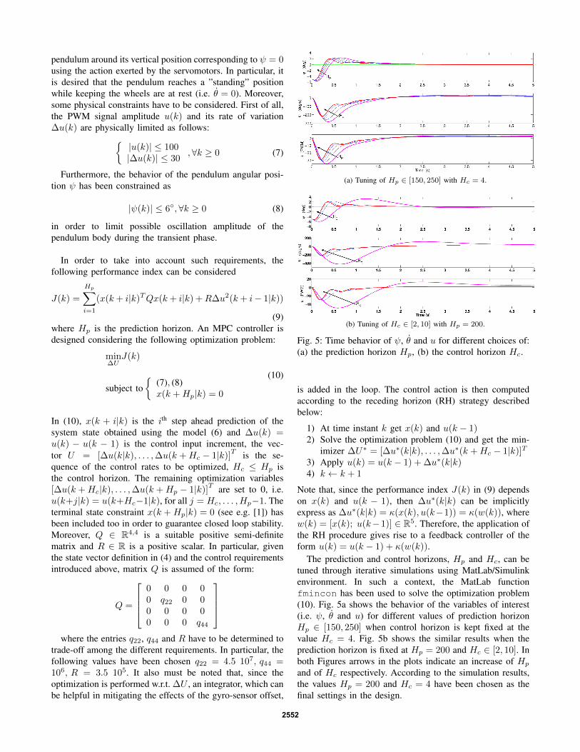
(a) Tuning of Hp ∈ [150, 250] with Hc = 4.
(b) Tuning of Hc ∈ [2, 10] with Hp = 200.
Fig. 5: Time behavior of ψ, θ and u for different choices of:(a) the prediction horizon Hp, (b) the control horizon Hc.
is added in the loop. The control action is then computedaccording to the receding horizon (RH) strategy describedbelow:
1) At time instant k get x(k) and u(k − 1)2) Solve the optimization problem (10) and get the min-
imizer ∆U∗ = [∆u∗(k|k), . . . ,∆u∗(k +Hc − 1|k)]T
3) Apply u(k) = u(k − 1) + ∆u∗(k|k)4) k ← k + 1
Note that, since the performance index J(k) in (9) dependson x(k) and u(k − 1), then ∆u∗(k|k) can be implicitlyexpress as ∆u∗(k|k) = κ(x(k), u(k−1)) = κ(w(k)), wherew(k) = [x(k); u(k−1)] ∈ R5. Therefore, the application ofthe RH procedure gives rise to a feedback controller of theform u(k) = u(k − 1) + κ(w(k)).
The prediction and control horizons, Hp and Hc, can betuned through iterative simulations using MatLab/Simulinkenvironment. In such a context, the MatLab functionfmincon has been used to solve the optimization problem(10). Fig. 5a shows the behavior of the variables of interest(i.e. ψ, θ and u) for different values of prediction horizonHp ∈ [150, 250] when control horizon is kept fixed at thevalue Hc = 4. Fig. 5b shows the similar results when theprediction horizon is fixed at Hp = 200 and Hc ∈ [2, 10]. Inboth Figures arrows in the plots indicate an increase of Hp
and of Hc respectively. According to the simulation results,the values Hp = 200 and Hc = 4 have been chosen as thefinal settings in the design.
2552

V. CONTROLLER IMPLEMENTATION AND EXPERIMENTALRESULTS
In this Section, implementation issues of the designedMPC controller are described. Note that, since the controlaction computation performed through the receding horizonstrategy can not be realized within the required sampling timeTs = 4 ms, a fast implementation procedure has to be used.In particular, the Nearest Point (NP) method introduced in[5], has been employed due to its low computational burdenand effectiveness in applications with small computing powersuch as the Mindstorms NXT (see also, in this regard,[11]). Basically, the NP method performs the implementationby approximating the control function κ(w) using a finitenumber ν of its values obtained via offline simulations ofthe controlled system. In this regard, the needed control lawvalues are computed over a compact subset Ω ⊂ R5 of thefunction κ(w) domain. Inside Ω, a finite number ν of pointsw` = x`, u−1,`, ` = 1, . . . , ν < ∞ is suitably chosen,giving rise to the set Ων = w` ∈ Ω, ` = 1, . . . , ν. Foreach value w ∈ Ων , the corresponding value ∆u = κ(w)is computed solving off-line the optimization problem (10).The values of w and ∆u are stored and successively used forthe on-line computation of the approximating function κNP .The set Ων is obtained by choosing variables w = [x; u−1]within the hyperbox:
Ω.= w : wl w wu ⊂ R5
where the symbol indicates element-wise inequalitiesand wl ∈ R5 and wu ∈ R5 represent, respectively, thevectors containing the chosen upper and lower bound of eachcomponent w`, ` = 1, . . . , 5 of w. Assuming that the valuesof w` within the interval [wl`, w
u` ], are chosen using a uniform
gridding procedure with a spacing amplitude of ∆wi, thenumber ns` of samples of each component w` is given by:
ns` = int
(wu` − wl`
∆w`
)+ 1
where int(·) is the nearest integer approximation. The valuesof ns` are chosen in order to obtain a suitable trade-offbetween accuracy and memory usage. Therefore, in theconsidered case case of a uniform gridding of Ω, the sizeνUG of the set is given by:
νUG =
5∏`=1
ns`
Once the elements wh, h = 1, . . . , νUG of the set have beendefined, the corresponding values ∆uh are computed. Thedata obtained in such a way (i.e. wh and ∆uh) are stored ina unique array WUG. For a given w, the NP approximationκNP (w) of the controller function κ(w), is the computed as:
κNP (w) = κ(wNP ) = ∆uNP (11)
wherewNP = arg min
w∈Ων‖w − w‖2 (12)
In order to speed up the computation of κNP , a suitablestructure for WUG should be employed. In particular, in[11], an effective structure has been introduced which allowsthe computation of wNP (and of ∆uNP ), through thedetermination of the row nNP of WUG where the neededvalue of has been stored (see [11] for details). At the eachsampling time, the control move u(k) is obtained by applyingthe following procedure:
1) Acquire x(k) and u(k − 1)2) Compute the index nNP
3) Get ∆uNP as WUG(nNP )4) Apply u(k) = u(k − 1) + ∆uNP
Fig. 6: Simulink realistic system model
In Table II, the gridding configuration chosen for this ap-plication is reported. This requires the off-line computationof 1279091 values of vector w. Each single incrementalcommand value ∆u is stored in a 8 bit signed integer. Thememory requirement for WUG is approximatively 1.3MB.This array has been stored in the Rabbit BL2600 memory.As a matter of fact, due to the sensor configuration describedin Section II, not all the states are measured. Therefore, aLuenberger observer, obtained using a linearised model ofthe state equation (6) has been added in order to providesuch state values starting from the measured values of θ, θand ψ. In order to test the system performance when theapproximate controller κNP is used, the accurate overallSimulink model reported in Fig. 6 has been realized. Thefinal configuration of κNP is tested simulating the controllerusing the realistic Simulink model. In particular, such amodel is made up by the following blocks: 1) the Plantblock contains the mechanical non linear model of the systemdepicted in Fig. 4; 2) the Actuators block models the PWMeffects; 3) the Sensors block models the generated analogsignals according to the sensors non linearities and therespectively noise models; 4) the AD/DA converters blockmodels the quantization and time delays effects introducedby the converters; 5) the Operating System contains thedigital controller algorithm coded with the nxtOSEK Mat-Lab Environment; 6) the Power Supply models the powerconsumption and battery discharging effects on the actuators.In Fig. 7 a comparison between the results obtained withthe MPC design described in the previous section (magentaline) and with the NP approximate controller (blue line)are reported. From Fig. 7 a quite good agreement between
2553

Fig. 7: Simulation and experimental results: (green line) thereference, (magenta line) simulation results for the idealMPC controller, (blue line) simulation results for the NPMPC controller, (red line) experimental results for the im-plemented NP MPC controller.
TABLE II: Uniform Gridding Configuration
Variable Num. of Points Min. Max.θ 11 −300 300
θ 31 −360 s−1 360 s−1
ψ 31 −10 10
ψ 11 −40 s−1 40 s−1
u(k − 1) 11 −100 100
the ideal MPC closed loop system performance and the onegoverned by the NP controller has been achieved. After theassessment of such a positive performance the NP controllerhas been implemented on the NXT-Lego system and thered line on Fig. 7 reports the behaviour of the recordedvariables on the real system. Observing Fig. 7, it can benoted that the behaviour of the simulated system and thereal one are quite close thus proving the effectiveness ofthe proposed design framework. A short video showing theachieved capabilities of the designed system is available athttp://staff.polito.it/massimo.canale/mpcNXT.html .
VI. CONCLUSION
In this paper, it has been shown how a low-cost LegoMindstorms NXT platform can be successfully employedin the education of the practical issues of Model PredictiveControl. A two wheeled inverted pendulum has been chosenas at-size scenario for the experimental practice. Controldesign and accurate simulations have been performed using asuitable tool developed in the MatLab/Simulink environment.Practical implementation of the controller has been realizedthrough the Nearest Point approximation technique via basicC programming under the nxtOSEK Real Time operatingsystems whose characteristics are similar to other platformsemployed in industrial applications. Experimental resultsshow the effectiveness of the introduced approach.
REFERENCES
[1] D. Q. Mayne, J. B. Rawlings, C. V. Rao, and P. Scokaert, “Con-strained model predictive control: Stability and optimality,” Automat-ica, vol. 36, pp. 789–814, 2000.
[2] S. Qin and T. Badgwell, “A survey of industrial model predictivecontrol technology,” Control engineering practice, vol. 11, no. 7, pp.733–764, 2003.
[3] T. Parisini and R. Zoppoli, “A receding-horizon regulator for nonlinearsystems and a neural approximation,” Automatica, vol. 31, no. 10, pp.1443–1451, 1995.
[4] A. Bemporad, M. Morari, V. Dua, and E. Pistikopoulos, “The ex-plicit linear quadratic regulator for constrained systems,” Automatica,vol. 38, pp. 3–20, 2002.
[5] M. Canale, L. Fagiano, and M. Milanese, “Set membership approx-imation theory for fast implementation of model predictive controllaws,” Automatica, vol. 45, no. 1, pp. 45–54, 2009.
[6] S. Richter, C. Jones, and M. Morari, “Real-time input-constrainedMPC using fast gradient methods.” in Proc. of the 48th IEEE Confer-ence on Decision and Control, 2009, p. 73877393.
[7] J. Wang and S. Boyd, “Fast model predictive control using onlineoptimization,” IEEE Transaction on Control Systems Technology,vol. 18, no. 2, pp. 267–278, 2010.
[8] A. Grancharova and T. Johansen, Explicit Nonlinear Model PredictiveControl, LNCIS 429. Berlin, Heidelberg: Springer Verlag, 2012.
[9] T. A. Johansen, “Approximate explicit receding horizon control ofconstrained nonlinear systems,” Automatica, vol. 40, pp. 293–300,2004.
[10] M. Canale, M. Milanese, and C. Novara, “Semi-active suspension con-trol using “fast” model-predictive techniques,” IEEE Transactions onControl System Technology, vol. 14, no. 6, pp. 1034–1046, November2006.
[11] M. Canale, L. Fagiano, and V. Razza, “Approximate nmpc for vehiclestability: design, implementation and sil testing,” Control engineeringpractice, vol. 18, pp. 630–639, 2010.
[12] S. Wadoo and R. Jain, “A lego based undergraduate control sys-tems laboratory,” in Systems, Applications and Technology Conference(LISAT), 2012 IEEE Long Island, may 2012, pp. 1 –6.
[13] Y. Kim, “Control systems lab using a lego mindstorms nxt motorsystem,” in Control Automation (MED), 2010 18th MediterraneanConference on, june 2010, pp. 173 –178.
[14] P. Richmond and D. Chen, “A model predictive control packagefor undergraduate education,” Education for Chemical Engineers,vol. 7, no. 2, pp. e43 – e50, 2012. [Online]. Available:http://www.sciencedirect.com/science/article/pii/S1749772812000024
[15] B.-Y. Shih, C.-Y. Chen, C.-W. Chen, and I. Hsin, “Using lego nxt toexplore scientific literacy in disaster prevention and rescue systems,”Natural Hazards, vol. 64, pp. 153–171, 2012. [Online]. Available:http://dx.doi.org/10.1007/s11069-012-0233-2
[16] S. Papert, The children’s machine: rethinking school in the age of thecomputer. New York, NY, USA: Basic Books, Inc., 1993.
[17] Lego. (2012, Oct.) Mindstorms NXT Hardware Developer Kit (HDK).[Online]. Available: http://mindstorms.lego.com/en-us/support/files/default.aspx
[18] M. Gasperi and P. Hurbain, Extreme NXT: Extending the LEGO MIND-STORMS NXT to the Next Level, Second Edition, ser. Technology inAction Series. Apress, 2009.
[19] T. Chikamasa. (2012, Oct.) nxtOSEK/JSP. [Online]. Available:http://lejos-osek.sf.net/
[20] HiTechnic. (2012, Oct.). [Online]. Available: http://www.hitechnic.com
[21] Digi. (2012, Oct.) RabbitBL 2600. [Online]. Available: http://www.digi.com
2554