A JV Company of ONGC, IL&FS and Govt. of Tripura R...
89
P P P R R R E E E - - - F F F E E E A A A S S S I I I B B B I I I L L L I I I T T T Y Y Y R R R E E E P P P O O O R R R T T T Additional 2 x 363.3 MW or Similar Capacity CCPP at Palatana, Tripura ONGC TRIPURA POWER COMPANY LIMITED A JV Company of ONGC, IL&FS and Govt. of Tripura December 2016 FICHTNER Consulting Engineers (India) Pvt Ltd Chennai, India
Transcript of A JV Company of ONGC, IL&FS and Govt. of Tripura R...

PP PRR R
EE E -- -
FF FEE E
AA ASS S
II I BB BII I LL L
II I TT TYY Y
RR REE E
PP POO O
RR RTT T
Additional 2 x 363.3 MW or Similar Capacity CCPP
at Palatana, Tripura
OONNGGCC TTRRIIPPUURRAA PPOOWWEERR CCOOMMPPAANNYY LLIIMMIITTEEDD A JV Company of ONGC, IL&FS and Govt. of Tripura
December 2016
FICHTNER Consulting Engineers (India) Pvt Ltd Chennai, India

ONGC Tripura Power Additional 2 x363.3 MW or Similar Capacity CCPP
Company Limited, Tripura Pre Feasibility Report
FCE-1114146-ME-DOC-PFR-3000-001,R2 FICHTNER INDIA Page :1-2
Table of Contents
1.0 Executive Summary ....................................................................................................... 1-1
1.1 Introduction.......................................................................................................... 1-1
1.2 Project Background ............................................................................................. 1-1
1.3 Site Location ........................................................................................................ 1-2
1.4 Project Site Data ................................................................................................. 1-2
1.5 Project Cost ......................................................................................................... 1-3
1.6 Project Completion Schedule .............................................................................. 1-3
1.7 Power Plant Details ............................................................................................. 1-4
1.8 Power Evacuation ............................................................................................... 1-4
2.0 Necessity and Justification of the Project ................................................................... 2-1
2.1 Introduction.......................................................................................................... 2-1
2.2 Past Power Supply and Demand Scenario in India ............................................. 2-1
2.3 Present Power Supply And Demand Scenario In India ....................................... 2-4
2.4 Expected Future Peak Power and Energy Requirement .................................... 2-5
2.5 Power Supply and Demand Position in North Eastern Region ........................... 2-6
2.6 Justification of the Project ................................................................................. 2-11
3.0 Availability of Land and InfrastrucTure at the Power Plant ....................................... 3-1
3.1 Criteria for Site Selection..................................................................................... 3-1
3.2 Assessment of Land Availability .......................................................................... 3-1
4.0 Fuel Source & Availability ............................................................................................. 4-1
4.1 Source and Type of Fuel ..................................................................................... 4-1
4.2 Annual Fuel Requirement, Availability and Mode of Transportation ................... 4-1
5.0 Water Source and Method of Drawl ............................................................................. 5-1
5.1 Plant Water Requirement .................................................................................... 5-1
5.2 River Water Intake and Pumping System ........................................................... 5-1
6.0 Power Evacuation Feasibility ........................................................................................ 6-1
6.1 Power Evacuation Arrangement for the Proposed CCPP ................................... 6-1
6.2 Start Up Power for the Proposed CCPP ............................................................. 6-2
6.3 Construction power for the proposed CCPP ....................................................... 6-3
7.0 Plant Description – Technical Features ....................................................................... 7-1
7.1 Explanation of Thermodynamic Cycle ................................................................. 7-1
7.2 Power Plant Configuration ................................................................................... 7-1
7.3 Main plant ............................................................................................................ 7-3

ONGC Tripura Power Additional 2 x363.3 MW or Similar Capacity CCPP
Company Limited, Tripura Pre Feasibility Report
FCE-1114146-ME-DOC-PFR-3000-001,R2 FICHTNER INDIA Page :1-3
7.4 Mechanical Auxiliary system ............................................................................... 7-8
8.0 Environmental and Pollution Aspects ......................................................................... 8-1
8.1 Introduction.......................................................................................................... 8-1
8.2 Air Pollution ......................................................................................................... 8-1
8.3 Water Pollution .................................................................................................... 8-3
8.4 Noise Pollution .................................................................................................... 8-5
8.5 Pollution Monitoring and Surveillance Systems .................................................. 8-6
8.6 Green Belt ........................................................................................................... 8-7
8.7 Guard Pond/ central monitoring basin (CMB) ..................................................... 8-7
9.0 Project cost Estimates & Tariff profiles ....................................................................... 9-1
9.1 General................................................................................................................ 9-1
9.2 Tariff Policy.......................................................................................................... 9-1
9.3 Project Cost Summary ........................................................................................ 9-2

1 Executive Summary

ONGC Tripura Power Additional 2 x363.3 MW or Similar Capacity CCPP
Company Limited, Tripura Pre Feasibility Report
FCE-1114146-ME-DOC-PFR-3000-001,R2 FICHTNER INDIA Page :1-1
1.0 EXECUTIVE SUMMARY
1.1 INTRODUCTION
The Electricity Act 2003 has opened up significant investment opportunities in the generation
sector by de-licensing electricity generation. The power generation market is entering a
competitive mode and cost of generation has become a critical parameter in determining the
long-term viability of projects. Gas based stations located well within the Gas grid offer most
economical power.
ONGC Tripura Power Company Ltd (OTPC) is sponsored by Oil and Natural Gas
Corporation (ONGC), Infrastructure Leasing and Financial Services Limited (IL&FS) and
Government of Tripura (GoT) have implemented a 726.6 MW Gas based CCPP at Palatana in
Tripura to supply power to the power deficit areas of North Eastern states of the country.
OTPC proposes to expand the present 726.6 MW Gas based CCPP by an additional
2 x 363.3 MW or similar capacity at Palatana, Tripura
OTPC has appointed Fichtner Consulting Engineers (I) Pvt. Ltd., Chennai as their Consultant
for the preparation of the Project Pre-Feasibility Report for the proposed expansion of the
Power Plant.
1.2 PROJECT BACKGROUND
Electricity consumption in India is increasing at a rate faster than over all energy supply. In
order to augment the availability of electricity, an initiative for environment friendly thermal
capacity development of 1,00,000 MW was proposed by GOI, with the aim to provide power to
all. To meet this demand, an urgent need is felt for a large scale thermal power development
programme in an environment friendly manner and also generate electricity at a competitive
price at the earliest.
The availability of the coal in India is plenty and it is very competitive. But the problem is
mining of coal, obtaining coal linkage, high ash content, Transportation of coal to the project
site and disposal of ash, long gestation period. Hydro & Nuclear power have also not lived up
to the expectation.
Oil & Natural Gas Corporation Ltd. (“ONGC”), a Fortune 500 company of the Government
of India, which is also a shared holder in OTPC, owns significant natural gas reserves in the
North Eastern state of Tripura. However, these natural gas reserves are yet to be
commercially developed due to low industrial demand in the North-Eastern region. The
complexities of logistics and attendant costs limit the economic viability of transportation of
gas to other parts of the country where gas is in deficit. In order to optimally utilize the gas

ONGC Tripura Power Additional 2 x363.3 MW or Similar Capacity CCPP
Company Limited, Tripura Pre Feasibility Report
FCE-1114146-ME-DOC-PFR-3000-001,R2 FICHTNER INDIA Page :1-2
available in Tripura, ONGC which has set up a 726.6 MW Gas based Combined Cycle
thermal power plant close to ONGC’s gas fields in the state of Tripura and supply power to the
deficit areas of North Eastern States of India and presently proposes to expand its capacity by
2 x 363.3 MW or similar capacity within a short gestation period.
The objective of this Project Pre-Feasibility Report is for preliminary evaluation of the project,
taking into consideration the proposed site characteristics, the technology available to set up
such large scale project and establish other details such as:
• Study the Proposed site, suitability, availability & adequacy of Land and other
infrastructure facilities
• Approach to site and Transportation of ODC consignment
• Study the availability of water source and examining the basic feasibility of bringing to site.
• Study the Fuel availability and connectivity to nearest network
• Study the power evacuation possibilities.
• Establish Basic plant configuration, salient technical features, project execution plan
• Examine the environment impact of such installation.
• Estimate the tentative project cost and cost of generation per unit of power
• Conclude the result of such study
1.3 SITE LOCATION
The Proposed capacity additional would at the existing power plant site located at Palatana In
district Udaipur In the state of Tripura. The proposed project site is located about 12 Kms from
The sub-district head quarters of Udaipur and is an about 60 Kms from the capital city of
Agartala. The project site is located adjacent to the existing state highway connecting to
Udaipur, with onward connectivity to Agartala by NH-44. A perennial river, namely Gumti flows
near the site and is proposed to source water required from this river for the proposed plant.
1.4 PROJECT SITE DATA
The summary of project information and meteorological data are follows: Location : Palatana village, Near Udaipur town, Tripura, India Power station site Elevation above Mean Seal Level (MSL)
: RL (+) 24.0
Latitude / Longitude : 23º 29’ 59.2” N and 91º 26’ 13.7”E Nearest Railway station : Manughat (Assam) Nearest Town : Udaipur (Tripura), India, Nearest State Highway : Udaipur-Kakraban State Highway

ONGC Tripura Power Additional 2 x363.3 MW or Similar Capacity CCPP
Company Limited, Tripura Pre Feasibility Report
FCE-1114146-ME-DOC-PFR-3000-001,R2 FICHTNER INDIA Page :1-3
Nearest Airport : Agartala Nearest Sea Port : Nearest seaport in Indian territory is Kolkata. Road Approach : Udaipur-Kakraban State Highway Seismic data Seismic intensity : As per IS-1893. Zone : V
Importance factor : 0.36
Temperature
Maximum / Minimum temperature : 37.5 0C and 6.7
0C
Daily maximum mean temperature : 30.5 0C
Daily minimum mean temperature : 20.5 0C
Design temperature for elec equipment/device/System
: 50 °C
Relative Humidity Maximum Relative Humidity : 100% Minimum Relative Humidity : 40% Max. recorded : 164.9 mm in 24 hrs Wind data Maximum wind speed : 55 m/s Climatic conditions :
1.5 PROJECT COST
Project costs summary are as follows:
Description Cost in Millions
Estimated Project cost 42107.36
Estimated Total Capital cost Per MW 50.58
1.6
1.6
1.6
1.6 PROJECT COMPLETION SCHEDULE
The commercial operation of Block-I is estimated to be 36 months from the date of Award of
Contract for EPC of proposed Power Plant. The second block would be staggered by
3 months, i.e., it will be put on commercial operation by end of 39th month from the date of
Award of Contract for EPC of proposed Power Plant.

ONGC Tripura Power Additional 2 x363.3 MW or Similar Capacity CCPP
Company Limited, Tripura Pre Feasibility Report
FCE-1114146-ME-DOC-PFR-3000-001,R2 FICHTNER INDIA Page :1-4
1.7 POWER PLANT DETAILS
The gas turbines are manufactured in standard models & ratings, and the capacity of gas
turbines varies from supplier to supplier, hence the exact gross capacity (site ref condition) of
726.6 MW will not be feasible. Hence the Nominal Gross Site Rating of unit would be
800±10% MW at Generator terminal, which would fairly cover wide spectrum of make & model
of gas turbines available with GE, Alstom, MHI and Siemens and also to obtain competitive
offer from them. The salient power plant details are indicated below:
• Plant configuration : 2 Blocks of 1GT+1 HRSG+1ST of either Single
shaft machine (both GT & ST coupled to
common generator) or Multi shaft machine
(separate generator for GT & ST) with common
facilities
• Plant capacity : 2 x 363.3 MW or similar capacity
• Fuel : Natural Gas as per Appendix-1
• Fuel requirement : 3.30 – 3.80 MMSCMD ( requirement will vary
based on GT model )
• Land requirement : 33 acres approx. at the existing power plant
• Water consumption : 25,370 m³/day approx.
1.8 POWER EVACUATION
The entire power generated will be evacuated through 400 kV transmission network from
project site at Pallatana. The expected power to be evacuated from the plant will be in the
order of approx. 678 MW after accounting for power consumption for entire plant auxiliaries.
The generators will be connected to the 400 kV switchyard through step-up transformers.
Already a 400kV double circuit transmission line is operating for evacuating power from the
existing power plant at Pallatana to Silchar (Assam) and Bongaigon (Assam) where PGCIL
400kV substation is located. Also another 400kV double circuit transmission line is available
from Pallatana project site to Suryamaninagar (Tiripura) and is presently operating at 132kV.
Once the 400kV substation work is completed at suryamanainagar, this line will be operating
on 400kV and further connected to Silchar 400kv substation. Each 400kV double circuit lines
will evacuate around 1060 MW power. Hence Power evacuation from the project site to the
other parts of the northeast region is possible and there are 400kV transmission line network
available.

2 Necessity and Justification
of the Project

ONGC Tripura Power Additional 2 x363.3 MW or Similar Capacity CCPP
Company Limited, Tripura Pre Feasibility Report
FCE-1114146-ME-DOC-PFR-3000-001,R2 FICHTNER INDIA Page :2-1
2.0 NECESSITY AND JUSTIFICATION OF THE PROJECT
2.1 INTRODUCTION
The power demand in the country is increasing rapidly due to rapid industrial and
infrastructure developments. The capacity addition at the present rate will not be able to meet
the projected demand and would result in a power deficit. To mitigate the gap between
demand and supply, Govt. of India is facilitating large scale capacity additions at shorter time
through public and private investments. In order to support the development of all the physical
and social infrastructures in the country, it is essential to supply reliable and uninterrupted
power. Given the current and projected peak load demand and using the indexation of
electricity ratio of electricity to industrial growth rate anticipated in the plan, the peak energy
demand for the country is expected to reach 2,83,470 MW in 2021-22 & rise up to
5,41,823 MW by 2032.
2.2 PAST POWER SUPPLY AND DEMAND SCENARIO IN INDIA
Remarkable growth and progress of the country have led to an extensive use of electricity in
the successive five-year plans. Over the years, the electricity Industry has made significant
progress, which is shown in the following graphs and tables.
Installed Capacity in Mega Watt (MW) from 1950 to 2016 (November)
Source: Ministry of Power

ONGC Tripura Power Additional 2 x363.3 MW or Similar Capacity CCPP
Company Limited, Tripura Pre Feasibility Report
FCE-1114146-ME-DOC-PFR-3000-001,R2 FICHTNER INDIA Page :2-2
Annual per Capita Consumption of Electricity
Source: Ministry of Power
Capacity addition in successive five year Plan, Targeted & Achieved is indicated below:
Plan Target Capacity
(MW) Achievement
(MW) %
1th (51-56) 1,300 1,100 84.6
2th (56-61) 3,500 2,250 64.3
3th (61-66) 7,040 4,520 64.2
4th (69-74) 9,264 4,579 49.4
5th (74-79) 12,499 10,202 81.6
6th (80-85) 19,666 14,226 72.3
7th (85-90) 22,245 21,401 96.2
8th (92-97) 30,538 16,423 53.8
9th (97-02) 40,245 19,015 47.2
10th (02-07) 41,110 21,180 51.5
11th (07-12) 78,700 53,000 67.3
12th (12-17)
# 88,537 75,195 84.9
*Source: CEA , # - till February 2016

ONGC Tripura Power Additional 2 x363.3 MW or Similar Capacity CCPP
Company Limited, Tripura Pre Feasibility Report
FCE-1114146-ME-DOC-PFR-3000-001,R2 FICHTNER INDIA Page :2-3
Power Demand Vs Supply Position in India
Period Demand (MW) Supply (MW) % of Deficit
2002-03 81,492 71,547 12.20
2003-04 84,574 75,066 11.24
2004-05 87,906 77,652 11.66
2005-06 93,255 81,792 12.29
2006-07 100,715 86,818 13.80
2007-08 108,886 90,793 16.62
2009-10 119,166 104,009 15.16
2011-12 130,006 116,191 10.6
2012-13 1,35,453 1,23,294 9.0
2013-14 1,35,918 1,29,815 4.5
2014-15 1,48,166 1,41,160 4.7
2015-16 1,53,366 1,48,463 3.2
Source: Power Ministry
Energy Requirement Vs Energy Supply Position in India
Period Demand (kWh) Supply (kWh) % of Deficit
2002-03 545,983 497,890 8.81
2003-04 559,264 519,398 7.13
2004-05 591,373 548,115 7.31
2005-06 631,757 578,819 8.38
2006-07 690,587 624,495 9.57
2007-08 737,052 664,660 9.82
2009-10 830,594 746,644 10.10
2011-12 937,199 857,886 8.5
2012-13 9,98,114 9,11,209 8.7
2013-14 10,02,257 9,59,829 4.2
2014-15 10,68,923 10,30,785 3.6
2015-16 11,14,408 10,90,850 2.1

ONGC Tripura Power Additional 2 x363.3 MW or Similar Capacity CCPP
Company Limited, Tripura Pre Feasibility Report
FCE-1114146-ME-DOC-PFR-3000-001,R2 FICHTNER INDIA Page :2-4
The installed generating capacity has increased by more than hundred times and annual per
capita consumption of electricity by about sixty folds in the last 70 years. The size and
expansion of transmission and distribution network has also increased substantially over the
years. The power plant capacity addition in the past (3-five year plan) is varying from
4200-18900 MW per annum to meet growing demand.
2.3 PRESENT POWER SUPPLY AND DEMAND SCENARIO IN INDIA
Over the years, the Electricity Industry has made significant progress, Installed capacity
increased from 1700 MW (1950) to 307.278 GW (Sept 2016). Annual per capita electrical
energy consumption is also increased from 16 kWh/annum (1950) to over 1075 kWh/annum
(2015-2016).
Installed Capacity in India
Type Installed Capacity (MW)
Hydro 43,112
Coal 186,493
Gas 25,057
Diesel 919
Nuclear 5,780
Renewable 45,917
Total 307,278
Source: Ministry of Power - 31.10.2016
Chart representation of installed power utilities in India – Sector wise and Source wise as on
31.10.2016.
Thermal69.1%
Hydel14%
Nuclear2%
Res15%
State33%
Central25%
Private42%

ONGC Tripura Power Additional 2 x363.3 MW or Similar Capacity CCPP
Company Limited, Tripura Pre Feasibility Report
FCE-1114146-ME-DOC-PFR-3000-001,R2 FICHTNER INDIA Page :2-5
All the three sectors namely Central, State and Private contribute to the availability of power in
the country. Major contribution comes from private sector followed by state and central. State
owns a share of about 33%, central owns a share of about 25% of installed capacity and the
rest by private sector. Major contribution of energy comes from thermal (about 69.1%)
followed by renewable (15%) energy
Even though there is huge capacity addition in recent periods, demand for electricity currently
outstrips supply. Inadequate generation, transmission, and distribution, as well as the
inefficient use of electricity, lead to shortages, particularly at peak times. Recognizing that
electricity is one of the key drivers of rapid economic growth and poverty reduction, the
Government of India is now encouraging all the resources to augment the capacity addition
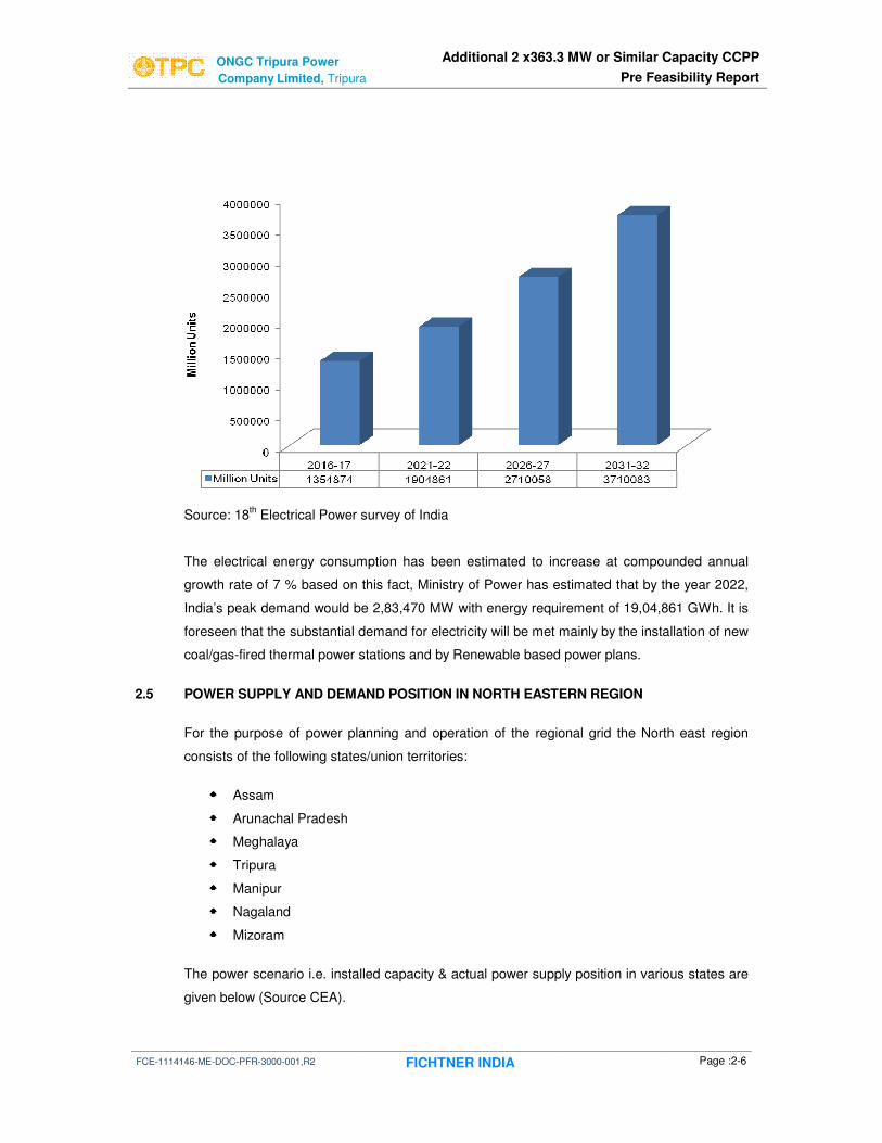
2.4 EXPECTED FUTURE PEAK POWER AND ENERGY REQUIREMENT
The projections of peak power and energy requirement of India until 2032 as per CEA,
Government of India are given below:
Source: 18
th Electrical Power survey of India
ONGC Tripura Power Additional 2 x363.3 MW or Similar Capacity CCPP
Company Limited, Tripura Pre Feasibility Report
FCE-1114146-ME-DOC-PFR-3000-001,R2 FICHTNER INDIA Page :2-6
Source: 18th Electrical Power survey of India
The electrical energy consumption has been estimated to increase at compounded annual
growth rate of 7 % based on this fact, Ministry of Power has estimated that by the year 2022,
India’s peak demand would be 2,83,470 MW with energy requirement of 19,04,861 GWh. It is
foreseen that the substantial demand for electricity will be met mainly by the installation of new
coal/gas-fired thermal power stations and by Renewable based power plans.
2.5 POWER SUPPLY AND DEMAND POSITION IN NORTH EASTERN REGION
For the purpose of power planning and operation of the regional grid the North east region
consists of the following states/union territories:
���� Assam
���� Arunachal Pradesh
���� Meghalaya
���� Tripura
���� Manipur
���� Nagaland
���� Mizoram
The power scenario i.e. installed capacity & actual power supply position in various states are
given below (Source CEA).

ONGC Tripura Power Additional 2 x363.3 MW or Similar Capacity CCPP
Company Limited, Tripura Pre Feasibility Report
FCE-1114146-ME-DOC-PFR-3000-001,R2 FICHTNER INDIA Page :2-7
2.5.1 Assam
Installed Capacity
S.No Sector Hydro Thermal Nuclear RES Total
1 State 100 336.2 0 30.01 466.21
2 Private 0 24.5 0 4.1 28.6
3 Central 329.72 544.92 0 0 874.64
Total Installed Capacity as on 29.02-2016 is 1369.45 MW, RES: Renewable Energy Source
2.5.2 Arunachal Pradesh
Installed Capacity
S.No Sector Hydro Thermal Nuclear RES Total
1 State 0 0 0 104.61 104.61
2 Private 0 0 0 0.27 0.27
3 Central 97.57 55.41 0 0 152.98
Total Installed Capacity as on 29.02-2016 is 257.86 MW, RES: Renewable Energy Source
2.5.3 Meghalaya Installed Capacity
S.No Sector Hydro Thermal Nuclear RES Total
1 State 282 0 0 31.03 313.03
2 Private 0 0 0 0 0
3 Central 74.58 122.84 0 0 197.42
Total Installed Capacity as on 29.02-2016 is 510.45 MW, RES: Renewable Energy Source
2.5.4 Tripura
Installed Capacity
S.No Sector Hydro Thermal Nuclear RES Total
1 State 0 169.5 0 16.01 185.51
2 Private 0 0 0 5 5
3 Central 62.37 423.62 0 0 485.99
Total Installed Capacity as on 29.02-2016 is 676.5 MW, RES: Renewable Energy Source

ONGC Tripura Power Additional 2 x363.3 MW or Similar Capacity CCPP
Company Limited, Tripura Pre Feasibility Report
FCE-1114146-ME-DOC-PFR-3000-001,R2 FICHTNER INDIA Page :2-8
2.5.5 Manipur
Installed Capacity
S.No Sector Hydro Thermal Nuclear RES Total
1 State 0 36 0 5.45 41.45
2 Private 0 0 0 0 0
3 Central 80.98 83.68 0 0 164.66
Total Installed Capacity as on 29.02-2016 is 206.1 MW, RES: Renewable Energy Source
2.5.6 Nagaland
Installed Capacity
S.No Sector Hydro Thermal Nuclear RES Total
1 State 0 0 0 29.67 29.67
2 Private 0 0 0 0 0
3 Central 53.32 57.05 0 0 110.37
Total Installed Capacity as on 29.02-2016 is 140.04 MW, RES: Renewable Energy Source
2.5.7 Mizoram
Installed Capacity
S.No Sector Hydro Thermal Nuclear RES Total
1 State 0 0 0 36.47 36.47
2 Private 0 0 0 0 0
3 Central 34.31 48.64 0 0 82.95
Total Installed Capacity as on 29.02-2016 is 119.42 MW, RES: Renewable Energy Source
2.5.8 Overview of North Eastern Region
Installed Capacity
S.No Sector Hydro Thermal Nuclear RES Total
1 State 382 541.7 0 253.25 1176.95
2 Private 0 24.5 0 9.37 33.87
3 Central 860 1478.1 0 0 2338.1
Total Installed Capacity as on 29.02-2016 is 3548.92 MW, RES: Renewable Energy Source
Power Supply Position (2015-2016)
Peak Demand (MW) Peak Met. (MW) Deficit (MW) % Deficit
2573 2367 -206 -8
Requirement (MU) Availability (MU) Deficit (MU) % Deficit
14,488 13,735 -753 -5.2
Source : http://www.cea.nic.in/reports/annual/lgbr/lgbr-2016.pdf

ONGC Tripura Power Additional 2 x363.3 MW or Similar Capacity CCPP
Company Limited, Tripura Pre Feasibility Report
FCE-1114146-ME-DOC-PFR-3000-001,R2 FICHTNER INDIA Page :2-9
Anticipated Power Supply Position (2016-2017)
Peak Demand (MW) Peak Met. (MW) Deficit (MW) % Deficit
2801 2695 -106 -3.8
Requirement (MU) Availability (MU) Deficit (MU) % Deficit
16,197 14,858 -1339 -8.3
Source : http://www.cea.nic.in/reports/annual/lgbr/lgbr-2016.pdf
Arunachal Pradesh, Manipur, Mizoram, Nagaland and Tripura faced energy shortages in the
range of 2.2-5.5%. The maximum energy shortage in North-Eastern Region was in Assam
and Meghalaya at 5.6% and 5.9% respectively.
2.5.9 Future Power Demand
The expected future power demand scenario for North eastern region is as mentioned
hereunder:
Source: 18th Electrical Power survey of India

ONGC Tripura Power Additional 2 x363.3 MW or Similar Capacity CCPP
Company Limited, Tripura Pre Feasibility Report
FCE-1114146-ME-DOC-PFR-3000-001,R2 FICHTNER INDIA Page :2-10
Source: 18th Electrical Power survey of India
Sl.No Power Position – North Eastern Region Unit Value
1 Present Install Capacity MW 3549
2 Present Peak Generation MW 2367
3 Present Calculated Load Factor (2)/(1) % 66
4 Power demand forecast at end of 13th Plan MW 4056
5 Expected Load factor (worst)-Refer (3) % 66
6 Estimated Installed Capacity required at end of 13
th
Plan (4)/(5) MW 6145
7 Additional capacity required per annum MW ~520
In order to support these developments in the north eastern region and to attract investors
(global and domestic); it is essential to supply reliable and uninterrupted power. Given the
current and projected peak load demand and using the indexation of electricity ratio of
electricity to industrial growth rate anticipated in the plan, the peak power demand for this
region is expected to reach 4,056 MW by year 2021-22 and rise up to 8,450 MW by 2031-32.
The power scenario in the region is discussed in detail and need for the proposed station is
studied in this section in the back drop of past and future power demands: viz:, present and
future generation capacities planned for bridging the gap. In order to narrow down the gap
between supply and demand, an urgent need is felt for a large scale power development
programme in an environment friendly manner.

ONGC Tripura Power Additional 2 x363.3 MW or Similar Capacity CCPP
Company Limited, Tripura Pre Feasibility Report
FCE-1114146-ME-DOC-PFR-3000-001,R2 FICHTNER INDIA Page :2-11
2.6 JUSTIFICATION OF THE PROJECT
A review of the power scenario brings out the fact that there is a deficit in the current scenario
as such and there is a requirement for additional capacity. The gap between demand and
supply of power is ever widening even after number of schemes implemented by the private,
state as well as central sector agencies. This situation is expected to continue for quite some
time indicating the need for capacity addition as much as feasible to reduce the gap between
supply and demand. The Government is therefore encouraging both public sector and private
sector to set up power plant to ensure adequate availability of power.
Oil & Natural Gas Corporation Ltd. (“ONGC”), public sector Company of the Government of
India, which is also a shareholder in OTPC, owns significant natural gas reserves in the North
Eastern state of Tripura. However, these natural gas reserves are yet to be commercially
developed due to low industrial demand in the North-Eastern region. The complexities of
logistics and attendant costs limit the economic viability of transportation of gas to other parts
of the country where gas is in deficit. In order to optimally utilize the gas available in Tripura,
ONGC which has set up a 726.6 MW Gas based Combined Cycle thermal power plant close
to ONGC’s gas fields in the state of Tripura and supply power to the deficit areas of North
Eastern States of India and presently proposes to expand its capacity by 2 x 363.3 MW or
similar capacity.
The location being close to the perennial river, cooling water for makeup is available in the site
for the power plant. Natural gas is being considered as main fuel further well developed
infrastructure facilities are readily available in the near proximity to the site. Taking all these
into consideration, establishment of the proposed expansion project of is well justified.

3 Availability of Land and
Infrastructure at the Power Plant

ONGC Tripura Power Additional 2 x363.3 MW or Similar Capacity CCPP
Company Limited, Tripura Pre Feasibility Report
FCE-1114146-ME-DOC-PFR-3000-001,R2 FICHTNER INDIA Page :3-1
3.0 AVAILABILITY OF LAND AND INFRASTRUCTURE AT THE POWER PLANT 3.1 CRITERIA FOR SITE SELECTION The important criterions to be considered for site selection are as follows:
i. Land requirement for setting up the proposed project facility shall be around 33 acres at a
stretch without any encumbrance in the plot area
ii. Availability of existing infrastructure facilities
iii. Hindrance free approach for transportation of heavy equipments
iv. Suitability of land from topography and geological aspects and the plateau of the project
site shall be as flat as possible
v. The project site shall be above flood level
3.2 ASSESSMENT OF LAND AVAILABILITY
OTPC has planned to put up additional 2x363.3MW or similar capacity gas based CCPP at
the existing combined cycle power plant. To assess the availability of land for the proposed
additional 2x363.3MW or similar capacity, site visits were undertaken and the details of the
visited site are as follows:
3.2.1 Power Block Area Space provision for locating the Power block for Phase-II project has already been identified
for one unit of 363.3 MW or similar capacity in the Plot Plan. Upon survey carried out during
site visit it is observed that a maximum of 2x363.3MW or similar capacity units can be
accommodated with relocation of following BoP areas:
(i) Plant road as shown in the following pictures to be shifted suitably towards North
(ii) Existing canteen building, Fire station building and fire drill tower to be relocated suitably
Power blocks for Phase-II can be located to the North of the Phase –I Power blocks. Snapshot
Phase –II power to be located is shown below:

ONGC Tripura Power Additional 2 x363.3 MW or Similar Capacity CCPP
Company Limited, Tripura Pre Feasibility Report
FCE-1114146-ME-DOC-PFR-3000-001,R2 FICHTNER INDIA Page :3-2
Snapshot of the proposed power block area
3.2.2 Control Room
Considering the space availability in the existing Control room of Phase-I, the control room
facility for Phase-II may also be accommodated. The existing conference hall in the control
room may suitably relocated to accommodate Phase-II control facility.
Space available on the North side of Phase – I Power Block to accommodate Phase – II Power Block. The plant Road above to be shifted towards North to accommodate Phase-II

ONGC Tripura Power Additional 2 x363.3 MW or Similar Capacity CCPP
Company Limited, Tripura Pre Feasibility Report
FCE-1114146-ME-DOC-PFR-3000-001,R2 FICHTNER INDIA Page :3-3
3.2.3 Switchyard
Switchyard 400kV for Phase – II (four bays) can be located on the Northern side of the
existing Phase– I switchyard. The spare bays presently earmarked in the Plot Plan to be also
used for accommodating the Phase-II switchyard. Snapshot showing the Phase-II switchyard
is as shown below
Space available on the North side of Phase – I switchyard to accommodate Phase – II 400kW switchyard

ONGC Tripura Power Additional 2 x363.3 MW or Similar Capacity CCPP
Company Limited, Tripura Pre Feasibility Report
FCE-1114146-ME-DOC-PFR-3000-001,R2 FICHTNER INDIA Page :3-4
3.2.4 Fuel Gas Area Based on discussions at site with OTPC it is understood that one gas terminal point at Fuel
gas area shall be provided by ONGC for Phase-II projects. Receiver, scrubber & flow meter
for fuel gas for Phase-II shall be accommodated in the Phase-I area. Hence, if ONGC is
appointed as the agency for supply of gas for Phase-II, gas receiving station for the same can
be accommodated in the existing station itself. Space available on the eastern side inside the
present station can be used for the same. A snap shot of fuel gas area is shown below:
Space available east of existing facility to accommodate the gas receiver, scrubber etc., for Phase – II

ONGC Tripura Power Additional 2 x363.3 MW or Similar Capacity CCPP
Company Limited, Tripura Pre Feasibility Report
FCE-1114146-ME-DOC-PFR-3000-001,R2 FICHTNER INDIA Page :3-5
Space identified for locating the Gas booster compressors for Phase-II projects shall be
adjacent to the Gas booster compressors of Phase-1. As an alternative option the fuel gas
conditioning system can also be located nearer to the gas booster compressor area instead of
locating the fuel gas conditioning system nearer to the power block area as placed in Phase-I.
3.2.5 Cooling Tower Area
Space for Phase-II gas booster station
Space for Phase – II cooling towers

ONGC Tripura Power Additional 2 x363.3 MW or Similar Capacity CCPP
Company Limited, Tripura Pre Feasibility Report
FCE-1114146-ME-DOC-PFR-3000-001,R2 FICHTNER INDIA Page :3-6
Induced draft cooling towers (IDCT) for Unit#3 of Phase-II can be located in the space as
identified in the Plot plan for future. Space identified for the IDCT for Unit#4 of Phase-II shall
be at back side of the workshop building. Snapshot of the space identified for IDCT for Unit#4
of Phase-II is as shown below.
3.2.6 Water System Area
Pre-treatment plant for Phase-II shall be located in the space as identified in the Plot plan for
future. Snapshot of the space identified for Pre-treatment plant such as Aerator,
Clariflocculator for Phase-II is as below:

ONGC Tripura Power Additional 2 x363.3 MW or Similar Capacity CCPP
Company Limited, Tripura Pre Feasibility Report
FCE-1114146-ME-DOC-PFR-3000-001,R2 FICHTNER INDIA Page :3-7
Alternatively high rate Lamella type clarifiers can be considered which shall occupy less space
compared to the rotary clariflocculators.
DM Plant for Phase-II shall be located in the space as identified in the Plot plan for future.
Snapshot of the space identified for DM Plant for Phase-II is as shown above
Effluent Treatment Plant (ETP) for Phase-II shall be located in the space as identified in the
Plot plan for future.
3.2.7 Non-Plant Buildings
Since the space identified for Power blocks of Phase-II falls under the area of Non-plant
buildings such as Fire station & Canteen which has already been constructed, the same may
have to be relocated at suitable location.
Space available for PT and DM Plant

ONGC Tripura Power Additional 2 x363.3 MW or Similar Capacity CCPP
Company Limited, Tripura Pre Feasibility Report
FCE-1114146-ME-DOC-PFR-3000-001,R2 FICHTNER INDIA Page :3-8
3.2.8 Accessibility and Transport Feasibility
Agartala, the capital of Tripura is connected by NH-44 between Agartala and Karimganj in
lower Assam, and further to Shillong in Meghalaya. The Proposed Site is approachable from
Agartala through State roads between Agartala-Udaipur-Kakraban. No new approach road
has been envisaged to the proposed project site since is located just adjacent to Udaipur-
Kakraban Road. Nevertheless, giving considerations to requirement of transportation of heavy
equipment for advanced class gas turbine based power plant, there will be constraints due to
existing transportation infrastructure inside the power plant as it requires minimum 25 M
radius. It is recommended to explore the possibility of approaching the power block area of
Phase-II for the Erection of GT by providing Temporary access through plant north side.
Entry for Phase II ODC equipment can be through an entry made in the North side plant wall here

ONGC Tripura Power Additional 2 x363.3 MW or Similar Capacity CCPP
Company Limited, Tripura Pre Feasibility Report
FCE-1114146-ME-DOC-PFR-3000-001,R2 FICHTNER INDIA Page :3-9
3.2.9 Laydown area for Phase – II Project Equipment
Lay down are for Phase – II Project equipment can be suitably allotted on the northern side of the plant as shown below.
3.2.10 Topographical and Geological Aspects
The plot area is generally at around 24 m above MSL. Topography of the proposed site
appears to be with undulation of variation from 24 m to 27 m and generally sloping towards
north side. Minor Filling/cutting works are anticipated. HT lines / Power cables are not passing
through the proposed site. However, the existing construction power lines which are passing

ONGC Tripura Power Additional 2 x363.3 MW or Similar Capacity CCPP
Company Limited, Tripura Pre Feasibility Report
FCE-1114146-ME-DOC-PFR-3000-001,R2 FICHTNER INDIA Page :3-10
through the proposed site shall be relocated. Topography survey and soil investigation study
have already been conducted during Phase-I of project. Hence, it is recommended to conduct
a limited topography survey and soil investigation study for the proposed additional units.
Drainage facilities have already been constructed during Phase-I of project. Type of
Foundation for power house building, main structures shall be based on geotechnical report.
3.2.11 Extent of Land Requirement
Based on the available Plot Plan (Rev.9), the utilization of the proposed plot is presented in
the Table 3.1 below:
Sl.
No. Description Unit
Phase-I (Existing
726.6MW)
Phase-II (proposed additional 2x363.3
MW or similar capacity )
1 Power Block - Area Acres 9.2 7.7
2 Switchyard Acres 12 6.4
3 Fuel Gas Area Acres 4 4
4 Water System Area Acres 3.5 3
5 Cooling Tower Area Acres 4 4
6 Reservoir Acres 21.7 8
Total Area for Plant, Building & Utilities
Acres 54.4 33.1
7 Admin Area Acres 3.5
8 Road & drains Acres 8
9 Green Belt Acres 96
Total Plot Area Acres 195
Table 3.1 Land Utilization
The plot area is about 195 acres of the land and it is adequate for putting up the proposed NG
based Combined Cycle Power Project considering two (2) blocks of (1GT+1HRSG+1ST)
additional 2x363.3 MW or similar capacity at the existing combined cycle power plant,
including adequate Green belt area.
Since the green belt area for Phase-II of the project can be accommodated in the Total plot
area, additional land catering to green belt may not be required to acquire.

4 Fuel Source & Availability

ONGC Tripura Power Additional 2 x363.3 MW or Similar Capacity CCPP
Company Limited, Tripura Pre Feasibility Report
FCE-1114146-ME-DOC-PFR-3000-001,R2 FICHTNER INDIA Page :4-1
4.0 FUEL SOURCE & AVAILABILITY 4.1 SOURCE AND TYPE OF FUEL
Fuel, which has been envisaged for the proposed power plant, is natural gas. Natural gas will
be supplied by ONGC through its pipeline from gas wells up to the proposed power plant
boundary.
The Analysis of natural gas, which has been assured by ONGC for the proposed power plant,
has been furnished in Appendix – 1. It has been noticed that, the proposed fuel gas is with
high Methane and is a sweet gas without compounds of sulphur. The proposed natural gas
has been found generally suitable for CCGT power plants after treatment and is also
environmental friendly.
For the proposed Unit #3, Natural gas will be supplied by ONGC from their gas wells at
Agartala / Dome, Baramura, Konaban, Sonamura, Tichana, and Gojalia.
Fuel Gas for Unit #4 may be sourced from either Jubilant fields in Tripura or ONGC’s fields in
Tripura.
4.2 ANNUAL FUEL REQUIREMENT, AVAILABILITY AND MODE OF TRANSPORTATION
Based on natural gas analysis furnished in this report, the annual requirement of fuel for
2 blocks with 800±10% MW Capacity (Nominal Gross Site Rating) and 85% plant load factor
is estimated to be 1260 Million SCM per year. The design net calorific value, which has been
considered for estimating the fuel gas consumption, is 8250 kcal/Sm3.
The annual average consumption of the gas (considering 85% PLF) 1260 Million SCM per
annum. However, the per day estimated gas for base load at design site ambient condition is
about 3.30 to 3.80 MMSCMD, which has been estimated based on the power plant
configurations, it’s make and model and the design ambient conditions as envisaged
elsewhere in this report. The actual per day requirement of natural gas would vary depending
on final gas turbine model to be selected based on competitive bidding as well as ambient
conditions - which is dynamic and the grid load patterns.

5 Water Source and Method of Drawl

ONGC Tripura Power Additional 2 x363.3 MW or Similar Capacity CCPP
Company Limited, Tripura Pre Feasibility Report
FCE-1114146-ME-DOC-PFR-3000-001,R2 FICHTNER INDIA Page :5-1
5.0 WATER SOURCE AND METHOD OF DRAWL
5.1 PLANT WATER REQUIREMENT
The total raw water requirement of proposed additional 2x363.3 MW or similar capacity
Combined Cycle Power Plant is as follows:
• CW Make-up : 17,952 m³/day
• DM Water Make-up to HRSG Cycle : 180 m³/day
• Neutralized Effluent from DM Plant : 50 m³/day
• Plant Service Water System : 240 m³/day
• Plant Potable Water System : 216 m³/day
• Total Fresh Water Requirement : 18,638 m³/day
• Expected Sludge in the River Water to Plant : 12 m³/day
• Total Fresh Water Requirement : 18,650 m³/day
• Recovery water from Blow down RO Plant : 6,720 m³/day
• Total Plant Water Requirement 25,370 m³/day
Water balance diagram for the proposed additional 2x363.3 MW or similar capacity CCPP is
attached as Exhibit-5.
5.2 RIVER WATER INTAKE AND PUMPING SYSTEM
The source of plant raw water shall be from the River Gumti. The location of existing river
water intake point and the pump house is at about 2.0 km from the Power Plant Site along the
pipeline route.
Currently, Four (4) Nos. (3 Working + 1 Standby) vertical River water pumps are operated at 8
hours per day continuous operation to cater the raw water requirement for 24 hours per day of
Phase-1 units (i.e. 2x363.3 MW). Currently, each pump is capable of developing the required
total head at rated capacity for 24 hours continuous operation i.e. 1100 m3 /h. Hence, the
pumps may be operated for the duration of 14 hours per day continuous operation to cater to
the raw water requirement for 24 hours per day of Phase-I & Phase-II.

ONGC Tripura Power Additional 2 x363.3 MW or Similar Capacity CCPP
Company Limited, Tripura Pre Feasibility Report
FCE-1114146-ME-DOC-PFR-3000-001,R2 FICHTNER INDIA Page :5-2
The existing raw water storage capacity is 1,78,000 m3. For the proposed expansion
considering the availability of land of about 8 acres adjacent to existing reservoir, additional
raw water reservoir to hold about 1,00,000 m3
will be provided. The proposed additional raw
water reservoir will be interconnected with the existing reservoir. The total storage capacity of
raw water reservoir will be increased to 2,78,000 m3 which will cater about 5 days storage
requirement of plant raw water for Phase-I & Phase II.
The location of raw water reservoir for Phase-II will be at south side of the existing raw water
reservoir where land is available.

6 Power Evacuation Feasibility

ONGC Tripura Power Additional 2 x363.3 MW or Similar Capacity CCPP
Company Limited, Tripura Pre Feasibility Report
FCE-1114146-ME-DOC-PFR-3000-001,R2 FICHTNER INDIA Page :6-1
6.0 POWER EVACUATION FEASIBILITY 6.1 POWER EVACUATION ARRANGEMENT FOR THE PROPOSED CCPP
The power generated from the existing 726.6 MW CCPP at Pallatana, Tripura is being
evacuated through 400kV switchyard (AIS) with one and half breaker configuration. 400kV
busbar current rating is 2000 Amps with fault level withstand capability of 40 kA for 1 sec.
There is a 132kV switchyard on southern side of the 400kV switchyard for drawing start up
power for the existing power plant. Startup power is derived through 132kV line from Bandwar
12 kms away from the power plant site. Both 400kV and 132kV switchyards are
interconnected using one no. Interconnecting Transformer (ICT).
To evacuate the power generated from the existing power plant, One (1) no. 400kV Double
Circuit Transmission line is provided from Pallatana (Power plant site) to Bongaigon (Assam)
receiving 400kV substation of PGCIL totaling 650kMs route length. These transmission lines
are passing through Silchar (Assam) 250kms from the power plant, Byrnihat, Azara and
reaches Boingaigon 400kV PGCIL substation.
The Pallatana-Bongaigon 400kV double circuit line has the capacity to evacuate around 1060
MW. The existing power plant to its full capacity will generate 726 MW. After the auxiliary
power consumption of 48 MW, the net power output for evacuation will be 678 MW. Hence
678 MW power from the existing power plant will be evacuated through the Pallatana-
Bongaigon 400kV double circuit lines. Since the 400kV double circuit Twin moose conductor
can evacuate 1060 MW, the existing 400kV double circuit line has some spare capacity of 382
MW. As a temporary measure depending upon local demand around 15MW is evacuated
using 132kV switchyard to Bandwar Substation.
From the existing 400kV switchyard there is another 400kV Double Circuit Transmission line
commissioned upto Surajmani Nagar approximately 40kms from power plant. This line further
extends to Silchar(Assam) 400kV substation. However this 400kV line is temporarily charged
with 132kV supply from 132kV switchyard to Surajmani Nagar substation. At Surajmaninagar
400kV substation work is under progress and is expected to be completed in the near future.
Once this 400kV substation work at Surajmani Nagar is completed, this double circuit line will
be shifted from 132 kV to 400kV side at both ends ie at Surajmaninagar and at power plant
switchyard side and will be operating on 400kV. This new line will further accommodate
additional 1060 MW capacity for evacuation. Hence the power generated 726MW from the
proposed power plant can be evacuated without any constraints. However PGCIL/relevant
grid network agency concurrence to receive 726MW (2x363.3 MW or similar capacity) at
Surajmani Nagar substation from new power plant need to be obtained, so that this
substation is adequately sized. A sketch showing the 400kV transmission network in the north
east region is attached as Exhibit-4.

ONGC Tripura Power Additional 2 x363.3 MW or Similar Capacity CCPP
Company Limited, Tripura Pre Feasibility Report
FCE-1114146-ME-DOC-PFR-3000-001,R2 FICHTNER INDIA Page :6-2
The existing 400kV switchyard is having sufficient space for extension of switchyard for the
proposed 2x363.3 MW or similar capacity CCPP. The existing 400kV switchyard can be
extended to accommodate all GT bays (ST3, GT3, ST4, GT4) and 2Nos O/G lines. Single
Line Diagram (Exhibit-3) showing the proposed extension of 400kV switchyard is attached.
The 11kV construction power lines crossing the area where the 400kV switchyard extension is
to be done and 11kV line and poles in the power block area also needs to be dismantled. The
small office and stores building in the switchyard extension area also to be dismantled as
these are temporary installations. However 400kV switchyard extension shall also be provided
with new switchyard control room as existing control room cannot accommodate new control ,
protection, metering panels and associated SCADA, DC system etc of extension switchyard.
The switchyard control room due to lack of space in the front side of switchyard, shall be
accommodated at the rear of the switchyard extension. By this arrangement, there will be two
switchyard control room building while this control can be centralized. Alternately 400kV GIS
(Gas Insulated Substation) can also be provided for the extension of 400kV switchyard in
such case control room will become part of the GIS building .This will save lot of space and
time of construction but expensive compared to AIS.
Conclusion points: Though space is available at the power plant end for new proposed
2x363.3 MW or similar capacity , equipment adequacy at receiving end substation, Surajmani
Nagar need to be checked with the relevant transmission utility(PGCIL/NETCL).
Load flow study shall be performed by PGCIL/NETCL for ensuring the power evacuation of
the power generated from the OTPC power plant through the 400 kV transmission lines
network and 400kV substations available and to study the magnitude of the voltage and phase
angle at each bus and the real and reactive power flowing in each line.
6.2 START UP POWER FOR THE PROPOSED CCPP For the existing power plant the startup power is drawn through 2 nos 132/6.9kV, 25MVA
station transformers from the 132 kV switchyard and these station transformers feeds power
to the unit buses for starting up of the GTs and STs of both the units. For similar arrangement
is to be followed for the proposed power plant, 2 nos station transformers shall be provided .
Station transformers for proposed power plant will be received through 2nos station
transformers and via 132kV switchyard. For this 2 nos bays to be added for which space is
available on the outgoing line side. Alternately to avoid station transformers, GCB scheme can
also be provided. In the GCB scheme start up power is drawn through Generator transformer
and UAT and generator is synchronized using GCB.

ONGC Tripura Power Additional 2 x363.3 MW or Similar Capacity CCPP
Company Limited, Tripura Pre Feasibility Report
FCE-1114146-ME-DOC-PFR-3000-001,R2 FICHTNER INDIA Page :6-3
6.3 CONSTRUCTION POWER FOR THE PROPOSED CCPP
The 33kV power supply already available from the Tripura state electricity shall be used for the
construction activities of the proposed power plant.

7 Plant Description – Technical Features

ONGC Tripura Power Additional 2 x363.3 MW or Similar Capacity CCPP
Company Limited, Tripura Pre Feasibility Report
FCE-1114146-ME-DOC-PFR-3000-001,R2 FICHTNER INDIA Page :7-1
7.0 PLANT DESCRIPTION – TECHNICAL FEATURES
7.1 EXPLANATION OF THERMODYNAMIC CYCLE In a combined cycle power plant (CCPP) a gas turbine generator generates electricity and the
waste heat is used to generate steam to produce additional electricity via a steam turbine; this
last step enhances the efficiency of electricity generation. The Gas turbine (GT) operates on
Brayton cycle; wherein the ambient air is drawn to compressor through filters and
compressed. In combustor, the compressed air is heated by combustion of fuel. The high
pressure-high temperature gas from combustor is expanded in turbine section to pressure just
good enough to drive the gas through the Heat Recover Steam Generator (HRSG) and stack.
The exhaust flue gas from gas turbine is still at very high temperature. This heat from exhaust
gas is recovered in HRSG to generate high pressure-high temperature steam, which in turn is
expanded in steam turbine (ST) and condensed to water in the attached surface condenser.
The condensate from the condenser is pumped back to HRSG. This steam-water cycle
connected to HRSG operates on Rankine cycle.
After absorbing the heat energy of GT exhaust gas in the HRSG, the flue gas will be
exhausted to atmosphere through the main stack.
7.2 POWER PLANT CONFIGURATION
7.2.1 Configuration of CCPP Plants
The combined-cycle system includes single-shaft or multi-shaft configurations. The single-
shaft system consists of one gas turbine, one steam turbine, one generator and one Heat
Recovery Steam Generator (HRSG), with the gas turbine and steam turbine coupled to the
single generator in a tandem arrangement on a single shaft.
Multi-shaft systems have one or more gas turbine-generators and HRSGs that supply steam
through a common header to a separate single steam turbine-generator.
Single and multiple-pressure reheat steam cycles are applied to combined-cycle systems
equipped with gas turbines having rating point exhaust gas temperatures of approximately
540°C or less. Selection of a single-or multiple-pressure steam cycle for a specific application
is determined by economic evaluation which considers plant installed cost, fuel cost and
quality, plant duty cycle, and operating and maintenance cost. Multiple-pressure reheat steam
cycles are applied to combined-cycle systems with gas turbines having rating point exhaust
gas temperatures of approximately 600 °C.

ONGC Tripura Power Additional 2 x363.3 MW or Similar Capacity CCPP
Company Limited, Tripura Pre Feasibility Report
FCE-1114146-ME-DOC-PFR-3000-001,R2 FICHTNER INDIA Page :7-2
The most efficient power generation cycles are those with unfired HRSGs with modular pre-
engineered components. These unfired steam cycles are also the lowest in cost.
Supplementary-fired combined-cycle systems are provided for specific application.
7.2.2 Criteria for Selection of Power Plant Configuration 7.2.2.1 No. of Power Blocks and Plant Capacity
Two (2) Nos. power block with advanced class GT has been envisaged to meet the required
Nominal Gross Site Rating of 800±10% MW at site Guarantee condition. Hence the Nominal
Gross site rating of unit will be 800±10% MW at Generator terminals, based on the available
GT Model & Ratings of reputed international suppliers’ viz., GE, Alstom, MHI and Siemens.
The gas turbines are manufactured in standard models and ratings, and the capacity of gas
turbines varies from supplier to supplier, hence it is not feasible to get the exact gross capacity
(site ref condition) of 726.6 MW. In view of this, the exact gross plant capacity can be declared
only after finalization of the Engineering, Procurement and Construction (EPC) Contractor for
the proposed power plant.
For the purpose of identification of configuration and further procurement actions, the
acceptable range of gross capacity of proposed plant has been considered as 800±10% MW
which would fairly cover wide spectrum of make and model of gas turbines available for the
purpose of study and competitive bidding. The final declared gross plant capacity will be
decided based on the selected model of GT during evaluation of proposal from EPC
Contractors.
7.2.2.2 Fuel Allocation and Utilization
The availability of natural gas for the proposed power plant is expected to meet the combined
capacity of about 800±10% MW. In order to utilize the available gas effectively, GTs with high
efficiency will be considered.
Further, for efficient utilization of natural gas, it is not envisaged to operate the power blocks in
simple cycle mode. Hence, provisions like bypass stack, diverter damper and guillotine
damper, which are required for simple cycle operation are not envisaged in the system design.
7.2.2.3 Number of GTs and Frame Size
In any Combined Cycle Gas Turbine (CCGT) based power plants, Gas Turbine Generator
(GTG) is the most expensive machine. Generally, the specific cost (Rs / kW) of GTG
decreases with increase of GTG rating. Further, for CCGT based power plants with GTGs of
higher ratings; the station building size, land requirement and other civil associated cost will be

ONGC Tripura Power Additional 2 x363.3 MW or Similar Capacity CCPP
Company Limited, Tripura Pre Feasibility Report
FCE-1114146-ME-DOC-PFR-3000-001,R2 FICHTNER INDIA Page :7-3
less when compared to CCGT plant configurations with more no. gas turbines of lower ratings.
In view of this, more emphasis has been given on CCGT plant configurations with higher
capacity gas turbine generators.
In the present day GT market, heavy-duty GTs are available in a capacity range of few
hundred kWs to as high as 270 MW which are of advanced class proven technology. Hence,
the GTs with gross ISO rating of about 270 MW (F-Technology of GE or equivalent) has been
considered as the upper limit.
In general, the above range covers spectrum of latest proven advanced class GTs and also
the one class prior to advanced class GTs.
7.2.2.4 Transportation Infrastructure
The weight and dimensions of the heaviest plant equipment is one of the major criteria in
deciding the plant configuration due to transportation constraint. OTPC have already carried
out Transportation Logistic Study during the initial stages of implementing Phase I of the
Project. The report confirms that transportation of heavy equipment weighing to
approximately 290Tons is feasible through water/road up to Pallatana Site. Single shaft
machine would be acceptable only after a similar transportation study is conducted and the
feasibleness is established for transportation.
7.2.3 Recommendation
Based on the various inputs, studies and analysis the following is recommended:
(I) If OTPC intends to retain the capacities for Block3 & 4 same as that of Blocks 1&2 it
would be prudent to have 9FA configurations of machines in order to maintain
interchangeability of spares across all the four Blocks
Alternatively
(II) If higher capacities can be considered then final selection of make and model of GT for
the proposed Power Plant can be through competitive bidding process and the
configuration to be adopted for the plant can be finalized based on the EPC bidder’s
guaranteed data and offered prices at the time bids evaluation. The target capacity for the
EPC bidding can be 800±10% MW providing options for the Bidders to choose single-
shaft or multi-shaft configuration. .
7.3 MAIN PLANT
Typical heat balance diagram for 100% MCR at Site Condition, with special Low NOx
combustor / equivalent and 0% make-up to steam-water cycle is presented in Exhibit-1.

ONGC Tripura Power Additional 2 x363.3 MW or Similar Capacity CCPP
Company Limited, Tripura Pre Feasibility Report
FCE-1114146-ME-DOC-PFR-3000-001,R2 FICHTNER INDIA Page :7-4
All the equipment / system of turbine and steam-water cycle of power block will be unitised.
7.3.1 Gas Turbine Generator and Accessories
The gas turbine will be heavy duty, advanced class type each comprising of a multistage
axial compressor and a turbine including combustors section.
The inlet air system would consist of a filter house with self-cleaning pulse jet type or two
stage static air filters, ducting and silencer. The system would draw atmospheric air into the
gas turbine compressor unit. Air intake silencer will suppress the noise in the intake air
system.
An inlet air guide vane will be provided in the compressor to improve the efficiency of the plant
under part load conditions. The turbine will have multiple stages. The exhaust gas from the
advance class gas turbines are generally in axial direction of the gas turbine. The gas turbine
units will have Dry Low NOx (DLN) combustors suitable for burning natural gas only.
Depending on the fuel gas specification of GT manufacturer’s, a water bath / steam heater
type fuel gas heater would be provided prior to combustor to ensure that no condensate
enters the combustor. Further, these heaters also would improve the net heat rate of the
Power plant, which is a consequential benefit. The combustion fuel mixture with air takes
place in the combustors and the hot gas will be expanded in the gas turbine, which will drive
the generator as well as axial flow air compressor. The gas turbine will have a rated speed of
3000 rpm for direct coupling with generator.
The gas turbine generator will be provided with lubrication oil system complete with lube oil
pumps, lube oil reservoir, and lube oil coolers.
The exhaust system of gas turbine will exhaust the gas into the atmosphere through HRSG. It is general practice with advanced class gas turbines to have a static frequency converter
(SFC) to use the generator itself as motor during starting of GT. This option eliminates the
starting motor / starting engine which are general features of the lower class gas turbines, but
the option of starting motor would also be available with some of the advanced class GT
suppliers. However, the option for SFC as well as Starting Motor will be given to EPC
Contractor and acceptance will be subjected to suitable design of transformer and plant
electrical system.
A fire detection and carbon dioxide / clean gas protection system as per GT manufacturer’s
standard practice (which will be generally compliant to recommendations of National Fire
Protection Association (NFPA) / equivalent norms) will be provided to protect the gas turbine
and its auxiliaries against fire hazard.

ONGC Tripura Power Additional 2 x363.3 MW or Similar Capacity CCPP
Company Limited, Tripura Pre Feasibility Report
FCE-1114146-ME-DOC-PFR-3000-001,R2 FICHTNER INDIA Page :7-5
7.3.2 Heat Recovery Steam Generators
The HRSGs, which have been contemplated for the proposed project, will be unfired type with
horizontal gas flow, natural circulation with triple pressure (High, Intermediate and Low
pressures) steam generation. The HRSGs will have the dry run capability in order to reduce
the black-start power consumption. The HRSG steam parameters have been indicated in
attached Exhibit-1 for Heat and Mass Balance Diagram. During EPC bidding, option will be
given to Bidder to consider even vertical HRSG.
HRSG will have a separate Superheater, Evaporator and Economizer sections to generate
High Pressure (HP), Intermediate Pressure (IP) and Low Pressure (LP) steams. Further, the
HRSGs will also have a reheater section where, the cold reheat steam from the HP turbine
after integration with IP steam from IP evaporator will be superheated. Steam temperature
control at each super heater section will be achieved with spray water attemperation. The
spray for attemperators will be tapped-off from HP feed water line.
In each HRSG, a condensate pre-heater (CPH) is envisaged to recover the thermal energy of
the hot gas to the maximum extent. The gas temperature at outlet of CPH is generally
governed by dew point temperature of oxides of sulphur. Though the sulphur content in the
gas is nil, the design exit gas temperature has been limited to 90ºC based on the optimisation
of the heat transfer area of condensate pre-heater.
It has been envisaged that the Deaerator will be integral part of the HRSG, which will be
getting heating steam from the LP evaporator. However, option will be given to EPC
Contractor for external Deaerator, where the heating steam for Deaerator would be supplied
from LP steam header after pressure regulation. Vent condenser would be provided with the
Deaerator to minimise wastage of steam. The Deaerator will be constant pressure, spray or
spray-cum-tray type and will be designed to deaerate all the incoming condensate to keep the
oxygen content of the deaerated condensate below the permissible limit, which generally is
0.005 cc/litre and maximum carbon dioxide in deaerated feed water would be nil. The steam
from LP evaporator will be used to peg the Deaerator during plant operation.
HRSG will be provided with internal thermal insulation, platforms and ladders as required.
Feed water and steam sampling arrangements as required would be provided.
HRSG will be provided with a 60 m high self-supporting steel stack. As such no sulphur has
been found in the natural gas fuel and hence, Central Pollution Control Board (CPCB) norms
based on sulphur in fuel would not be the governing factor for stack height. Stack height has
been arrived to balance the net draft available at stack inlet; however, this will also assist in
better dispersion of hot flue gas from HRSG and NOx emission.

ONGC Tripura Power Additional 2 x363.3 MW or Similar Capacity CCPP
Company Limited, Tripura Pre Feasibility Report
FCE-1114146-ME-DOC-PFR-3000-001,R2 FICHTNER INDIA Page :7-6
Steam from the HRSGs would be supplied to a steam turbine through steam piping.
Intermediate-pressure (IP) and Low-pressure (LP) bypass systems of 100% HRSG capacity
will be provided for dumping the IP and LP steam to the condenser during start-up and turbine
trip conditions. During bypass condition, the HP steam will be depressurized and
desuperheated to cold reheat steam condition and will be integrated with IP steam before
HRSG reheater section. Each bypass station will be provided with pressure reducing valves
and attemperators as necessary. The spray water for attemperation would be tapped-off from
HP feed water line.
7.3.3 Steam Turbine and Auxiliaries
For the purpose of this project report, non-extraction, re-heat, condensing type steam turbine
has been considered. The MCR rating of Steam Turbine Generator at Site ambient condition
is presented in attached Exhibit-1 for Heat and Mass Balance Diagram.
The steam entry to the turbine would be through a set of emergency stop and control valves,
which would govern the speed / load of the machine. The turbine control system would be of
electro-hydraulic type with hydro-mechanical system as a backup.
The steam turbine would be complete with lube oil and control oil system, jacking oil system,
governing system, protection system and gland sealing steam system. The lube oil system of
the STG will be provided with 2x100% online centrifuge system.
The gland sealing steam for the steam turbines would be taken from HP steam and will be de-
pressurized and de-superheated before supply to turbine glands. The spray water for de-
superheating would be taken from IP feed water line.
7.3.4 Condensing Equipment & Auxiliaries
The steam turbine would be provided with a surface type condenser fixed to the turbine
exhaust for condensing the exhaust steam from the steam turbine. The condenser would be
of radial or axial or lateral configuration with rigid or spring mounting arrangement as per EPC
Contractor’s standard practice.
The condenser design will be ensured to prevent sub-cooling of condensate below saturation
temperature corresponding to respective condenser backpressure under any of the operating
conditions. While deciding the heat duty of the condenser, the heat load during steam
dumping will also be considered as one of the operating conditions. Oxygen content of
condensate leaving the condenser hot well will be ensured not to exceed 0.03 cc/litre over the
entire range of load. The design will be to satisfy the requirement of Heat Exchanger Institute
(HEI), USA.

ONGC Tripura Power Additional 2 x363.3 MW or Similar Capacity CCPP
Company Limited, Tripura Pre Feasibility Report
FCE-1114146-ME-DOC-PFR-3000-001,R2 FICHTNER INDIA Page :7-7
Two (2) nos. (1 working + 1 standby) capacity vacuum pumps or steam jet air ejectors will be
provided to maintain the vacuum in the condenser by expelling the non-condensable gases.
One vacuum pump would operate during normal plant operation and during start-up, both the
vacuum pumps may be operated such that, the desired vacuum can be pulled within a
shortest possible time. In the alternative option of using steam jet ejector, one starting steam
jet air ejector of higher capacity will be provided for quick evacuation of gases from the
condenser during start-up. Steam for the ejectors will be supplied from the HP steam header
after de-pressurising and de-superheating. The design of vacuum system and it’s sizing will be
as per requirement of HEI.
7.3.5 Condensate Extraction Pumps (CEP)
Two (2) nos. (1 working + 1 standby) CEP would be provided to pump the condensate from
the hot well to Deaerator through the CPH of the HRSG. The condensate extraction pumps
will be vertical motor driven centrifugal canister type with flanged connections.
Connections for condensate supply to the following major services will be tapped-off from this
condensate discharge header:
• Turbine exhaust hood spray.
• Gland sealing system de-superheating. The condensate will then pass in series through the gland steam condenser before entering
the CPH section of HRSG.
7.3.6 Boiler Feed Pumps (BFP) and Drives
Two (2) nos. (1 working + 1 standby) horizontal, multi-stage, barrel casing / ring section,
centrifugal type BFP, driven by electric motor, will be provided for HP feed System. Each HP
BFP would have one (1) no. matching capacity, single-stage booster pump (if required) driven
by the feed pump motor. The booster pump will take suction from feed water storage tank and
discharge into the suction of corresponding main BFP, which in turn will supply feed water to
HP section of HRSG through HP feed water control station. HP feed water control station
comprising of Two (2) nos. (1 working + 1 standby) pneumatic control valves of 100% and one
(1) no. 30% capacity pneumatic control valve is envisaged to control the HP drum level. Each
feed water control valves will be provided with motor driven upstream isolation valve and a
downstream isolation valve with manual operator for maintenance of internals of control valve.
A similar arrangement would be provided for IP System. The type of IP BFP would be ring
section type. Alternatively, it is also possible to provide a feed for IP Section from bleed-off HP
BFP. The option will be given to Contractor for selection of independent IP BFP or bleed-off
type HP BFP to feed IP System.

ONGC Tripura Power Additional 2 x363.3 MW or Similar Capacity CCPP
Company Limited, Tripura Pre Feasibility Report
FCE-1114146-ME-DOC-PFR-3000-001,R2 FICHTNER INDIA Page :7-8
The LP section of the HRSG will be taking the feed water from feed water tank of integral
Deaerator; hence, no BFP will be required for LP System.
7.3.7 Chemical Dosing System
Although high purity water will be used as heat cycle make-up, careful chemical conditioning
of the feed steam condensate cycle is essential as a safeguard against corrosion and possible
scale formation due to ingress of contaminants in the make-up system. Chemical feed system
will comprise of the following:
7.3.7.1 Hydrazine System
The most harmful contaminant, which is always present in the make-up water, causing serious
corrosion in the high-pressure boiler is dissolved oxygen. Hydrazine solution will be used to
deoxygenate / wipe-off traces of dissolved oxygen left over in the feed water after Deaerator.
7.3.7.2 Phosphate Dosing System
The rate of corrosion on mild steel surface is lowest when the solution in contact has a pH
within 9 to 10.
To impart desired alkalinity to boiler water and also to safely remove scale-forming compound
in water, if any, due to system contamination as non-adherent harmless precipitate, tri-sodium
phosphate solution will be added in the boiler drum. Proper attention is required so that, the
alkalinity does not become excessive, as in such case the corrosion rate will go on increasing.
Generally, the following residual phosphate level will be maintained in the drums:
• 40 mg/l for drum pressure < 50 kg/cm²(a)
• 10 mg/l for drum pressure > 50 kg/cm²(a) & < 70 kg/cm²(a)
• 5 mg/l for drum pressure > 70 kg/cm²(a) & < 175 kg/cm²(a)
Phosphate dosing systems will be provided and the Phosphate preparation and dosing system
would be skid mounted with solution preparation-cum-feed tanks, agitators / mixers, metering
pumps, piping, valves and fittings. The tank and all the pumps will have 100% redundancy
7.4 MECHANICAL AUXILIARY SYSTEM 7.4.1 Fuel Conditioning System
Though the natural gas fuel for the proposed power plant is generally good, it cannot be used
in gas turbines due to stringent fuel gas specifications of GT manufacturers and high pressure
requirement of advanced class GTs. To meet the fuel gas specifications of gas turbine
manufacturer, necessary conditioning system for natural gas has envisaged as a part of this
power plant project.

ONGC Tripura Power Additional 2 x363.3 MW or Similar Capacity CCPP
Company Limited, Tripura Pre Feasibility Report
FCE-1114146-ME-DOC-PFR-3000-001,R2 FICHTNER INDIA Page :7-9
The gas conditioning process generally comprises removing condensates, filtration, etc.
At terminal point of gas supply pipeline , a common pneumatic / solenoid operated emergency
shutdown valve (ESD) with appropriately sized vent as per American Petroleum Institute (API)
standard will be provided to depressurise the downstream line upon closure of ESD valve. The
ESD valve will operate only during fire hazard in plant and will not have any interlocks. The
ESD valve will close on signal from control room / fire panel. A manual bypass valve will be
provided to ESD valve for operation during maintenance of ESD.
One (1) no. common flow meter will be provided near terminal point for internal fuel auditing.
The flow meter would be orifice type with ±1% accuracy. An upstream and downstream
isolation valve with a bypass valve will be provided to enable the maintenance of flow meter.
The gas stream will be provided with knockout drum to remove condensate and a cartridge
filter to remove particulate matters in the influent natural gas before admitting to GT.
The natural gas will be supplied with the required pressure by the Gas supply agency.
However, gas booster compressor shall be envisaged to meet the pressure requirement of the
selected gas turbine. A control valve would be provided to regulate the gas pressure.
GT will be provided with a final filter to remove the condensate formed during the compression
as well as ingress of particulates in compressor and piping system. The final filter will be of
stainless construction with coalescent type filtration. Further, the downstream piping from final
filter to GT will be stainless steel. In order to reduce the cost towards stainless steel piping, the
final filters will be located close to gas turbines.
Before gas turbine, One (1) no. orifice type flow meter similar to one near Gas supply agency
terminal will be provided for internal gas auditing.
The gas conditions at turbine flange will be as follows:
Water Content : <0.01 % Wt
Sediments : </=20 ppm (wt)
Particulates
D < 10 : </= 18 ppm (wt)
10 </= d </= 25 : </=2 ppm (wt)
D > 25 : 0 ppm (wt)
Pressure : 26 ± 2 bar, but it may be higher depending on GT
model.

ONGC Tripura Power Additional 2 x363.3 MW or Similar Capacity CCPP
Company Limited, Tripura Pre Feasibility Report
FCE-1114146-ME-DOC-PFR-3000-001,R2 FICHTNER INDIA Page :7-10
Temperature : Superheated above dew points as per Fuel Gas
Specification of GT supplier. It will be endured to
conserve the heat of compression in gas compressor
to ensure the above superheated temperature.
If required, a hot water bath / steam type fuel gas heater will be provided to ensure the
required superheat of gas as well to enhance the plant efficiency. The required steam for
heating would be taken from IP evaporator outlet / IP drum.
One (1) no. common gas condensate tank of adequate capacity will be provided to collect the
gas condensates if any from the conditioning skid / GT.
Adequate safety features will be built-in the gas system to protect the operating personal and
the property against fire hazards. Adequate no. of purging points with nitrogen supply will be
provided to purge the system during maintenance. One (1) no. common cold stack of
adequate height will be provided at safe location on gas conditioning area, to which all the vent
lines of gas system will be connected to disperse the system vents during maintenance and
safety valve pop-ups. During normal operation, no continuous fuel gas venting is envisaged,
hence no hot flare is being provided.
7.4.2 Cooling Water System
The proposed power plant being located close to water source, closed cycle cooling water
system has been considered for surface condenser of steam-water cycle.
Three (3) nos. (2 working + 1 standby) Cooling Water (CW) pumps of vertical type for each
unit have been considered to supply cooling water to STG condenser. The CW pumps will be
located in a cooling water pump sumps, which will receive cooled return water from the
cooling tower basin. The cooling water sumps and CW forebay will be sized as per guidelines
of Hydraulic Institute Standard.
Considering the high humidity and being located inland, Induced Draft Cooling Tower (IDCT)
is considered for proposed power plant to cool the hot return water from Surface Condenser of
ST. Generally, the construction period of IDCT is less when compared to natural draft cooling
tower, which is an added advantage.
The IDCT will have cells each comprising of fans and film type PVC fills mounted on RCC
basin. It is proposed to provide adequate Nos. IDCT cells with one no. cell as a spare. The
cooling tower cells will be arranged in-line/back to back to reduce the re-circulation of hot air
and to ensure effective cold airflow to cooling towers. The cooling tower would be designed for
a cooling range of 10°C. Cooling water cell will be provided with common cold-water basin,
with an outlet with trash screen and gate. The cold-water basin will be sized to hold 6 minutes

ONGC Tripura Power Additional 2 x363.3 MW or Similar Capacity CCPP
Company Limited, Tripura Pre Feasibility Report
FCE-1114146-ME-DOC-PFR-3000-001,R2 FICHTNER INDIA Page :7-11
water flow (between liquid levels corresponding to normal operating level and low-low level /
level corresponding to trip of CW pumps in CW forebay) from respective cell.
The make-up for the cooling water system will be from clarified water. The cooling water
make-up pumps would start and stop based on level signals from level switches in forebay. To
ensure adequate dissolvability of scales, the CW system make-up is sized based on optimum
cycle of concentration (COC) - hence, no anti-scalants / dispersants chemical dosing have
been envisaged for CW system. It is recommended to use package chemicals to attain higher
COCs provided the discharge parameters are within the statutory norms. However, chlorine
gas dosing system will be provided to prevent formation of algae and other biological growths.
The CW chlorination system would comprise chlorine tonners, evaporators, motive water
pumps, chlorinators, chlorine gas distribution system, chlorine leak gas absorption system,
etc. The chlorination system equipment will be located in a room adjacent to CW Pump
house. The Chlorination system will be sized to dose 5 mg/l of CW water in the system for 30
minutes per 8-hour shift. The total number of tonners per block will be based on requirements
of 15 days of chlorine requirement of respective block.
7.4.3 Auxiliary Cooling Water (ACW) and Closed Cooling Water (CCW) System
The CCW system meets the cooling water requirements of all the auxiliary equipment of the
GTG, STG and HRSG units such as turbine lube oil coolers, generator coolers, BFP
auxiliaries, condensate pump bearings, sample coolers and air compressors auxiliaries. The
GTG and STG / HRSG auxiliaries will be provided with an individual ACW systems since the
pressure requirements of cooling water system of GTG is generally high when compared to
auxiliaries of STG and HRSG.
The primary side of this cooling water system for auxiliaries, i.e., circulating cooling water
(CCW) system will make use the passivated DM water as cooling medium, which will be
circulated in closed circuit through plate heat exchanger and auxiliary coolers in series. Two
(2) nos. (1 working + 1 standby) CCW pumps per circuit will be provided to circulate the water
in closed primary circuit. An overhead expansion tank of adequate capacity will be provided to
ensure positive suction to the CCW pumps as well as will allow the expansion of water in
closed circuit. There would be loss in water level in CCW circuit due gland leakage at pumps,
leakages in flanged connections, at plate heat exchanger seals, etc. To make-up this loss, the
make-up water would be supplied from CEP discharge during normal operation. Solenoid
operated level control valve will be provided on expansion tank to ensure the level in tank.
During initial fill for the system, water will be supplied from HRSG fill pumps discharge. A
chemical feed system will be provided to add chemicals for passivation of DM water and
ensure adequate pH value.

ONGC Tripura Power Additional 2 x363.3 MW or Similar Capacity CCPP
Company Limited, Tripura Pre Feasibility Report
FCE-1114146-ME-DOC-PFR-3000-001,R2 FICHTNER INDIA Page :7-12
The hot water from auxiliary coolers in primary circuit will dissipate the heat to cooling water
from Condenser cooling water system in secondary circuit. For this purpose, two (2) nos.
(1 working + 1 standby) Plate Heat Exchangers (PHE) per each circuit has been envisaged.
The cooling water in secondary circuit (ACW system) will be cooled in turn in IDCT of
condenser cooling water system. Two (2) nos. (1 working + 1 standby) ACW pumps per circuit
will be provided to circulate the water in secondary cycle through plate heat exchanger and
IDCT. The ACW pumps will be located in CW Pump house and will take suction from cooling
water sump.
7.4.4 Central Lube Oil System
The plant will be provided with central lube oil system for the purpose of storing and treatment
of lube oil for Steam turbine and auxiliaries. Generally, for the gas turbine, the manufacturers
would not accept to use the treated lube oil. For gas turbine lube oil system, the properties will
be monitored at regular interval and will be replaced after the properties deteriorate beyond
the recommended values by manufacturer.
7.4.5 Fire Fighting System
For protection of power plant equipment and operating personal against fire, any one or a
combination of the following systems will be provided for all yards, areas, buildings and
equipment:
• Hydrant system – Entire Plant,
• Medium Velocity Water Spray System – Cable Gallery, Fuel oil tanks and EDG building.
• High Velocity Water Spray System – Transformers, Lube oil skids and Hydraulic oil skids,
• CO2 / Clean Agent Systems – Switchgear Rooms, Control Rooms,
• Sprinkler System for fire water pump house,
• Foam cabinets and portable foam system,
• Fire resistant doors and fire seal walls will be provided as per code requirements.
• Portable and Mobile Fire Extinguishers – Entire Plant,
• Fire detection and alarm system for main control room, Control equipment room, UPS
room, Switchgear room, Cable spreader room, Battery and battery charger room.
The system will be designed in conformity with the recommendations of the Tariff Advisory
Committee (TAC) of Insurance Association of India.
The recommendations of National Fire Protection Association (NFPA), USA / equivalent will
be followed, as applicable.

ONGC Tripura Power Additional 2 x363.3 MW or Similar Capacity CCPP
Company Limited, Tripura Pre Feasibility Report
FCE-1114146-ME-DOC-PFR-3000-001,R2 FICHTNER INDIA Page :7-13
The source of water for firewater pumps of hydrant network and water spray will be from the
clarified water tanks. A reserve water level will be maintained in the sump as per TAC
requirements.
Adequate number of engine driven firewater pumps & motor driven pumps will provided to
cater water to firewater network. In addition to the above, jockey pump sets, hydro-pneumatic
tanks, compressors, pipes and fittings as required will be provided.
Hydrant system will feed pressurized water to hydrant valves located throughout the plant and
also at strategic locations within the powerhouse.
7.4.6 Compressed Air System
Two (2) nos. (1 working + 1 Standby) plant oil free screw type air compressors of adequate
capacity & discharge pressure along with instrument air drying system & compressed air
receiver will be provided to cater the plant compressed air requirement. The service air
system and the instrument air system will be separate in all respects.
7.4.7 Cranes & Hoisting Equipment EOT Crane for the GT & STG area will be provided. The capacity of this Crane will be decided
based on heaviest equipment to be handled during maintenance
For all other area suitable cranes & hoist will be provided for maintenance of the equipment. 7.4.8 Air Conditioning System
Various control rooms in power station - houses a group of sophisticated and precision control
panel and desks, which call for controlled environments for proper functioning. For control
rooms, the objective of air-conditioning is to maintain conditions suitable for satisfactory
functioning of sophisticated equipment, accessories and controls and also for personnel
comfort. Besides these, the service areas viz. instrument and relay testing laboratories
chemical laboratory and a few offices are envisaged to be air-conditioned.
The following areas are proposed to be air-conditioned:
• All unit control rooms, local control rooms, computer rooms, control equipment rooms.
• Switchyard control room.
• Service areas viz., chemical laboratories, I&C testing laboratory, relay and meters testing
laboratory, SWAS (dry panel area) and gas analyser rooms, etc.
• Engineer rooms and Office areas.

ONGC Tripura Power Additional 2 x363.3 MW or Similar Capacity CCPP
Company Limited, Tripura Pre Feasibility Report
FCE-1114146-ME-DOC-PFR-3000-001,R2 FICHTNER INDIA Page :7-14
To cater to the above requirement the following systems are proposed: For major control rooms and other blocks with higher heat loads and which require
sophisticated control system, packaged type water cooled chiller with minimum one no. unit as
a standby will be provided. Each system will be complete with air handling unit, chiller unit and
a dry cooling tower with cooling air fan, associated piping with valves, fittings etc. These air
conditioning systems will have interlocks with fire detection system of the respective rooms to
trip upon fire signal from detectors.
For other areas, packaged air conditioners / split type air conditions as suitable will be
provided.
7.4.9 Ventilation System
For all the areas other than air-conditioned area the general ventilation system will be provided
with the following objective:
• Dust-free comfortable working environment.
• Scavenging out heat gain through walls, roofs, etc. and heat load from various equipment,
hot pipes, lighting, etc.
• Dilution of polluted air due to generation of obnoxious gaseous / aerosol contaminants like
acid fumes, dusts, etc.
Power block, electrical switchgear rooms, cable galleries and other rooms with substantial
heat loads or having requirement of dust free environment will be provided with package type
ambient air supply units comprising unitary air filtration section comprising of fresh air intake
louvers, automatically cleanable nylon filter (with water spray) & moisture eliminator and,
blower section comprising centrifugal fan & volume control dampers. The air will be drawn
through filters section and supplied ventilated space through ducting, grilles etc. The water for
filter cleaning will be re-circulated by means of centrifugal pumps. The supplied air will be
exhausted through wall-mounted gravity operated dampers to maintain slightly positive
pressure to reduce ingress of dust.
For chlorination equipment room, the supply air unit similar to power block will be provided
however, the exhaust will be ducted and vented out with exhaust fan. In chlorination
equipment room, slightly negative pressure will be maintained to ensure the directed exhaust
of leak chlorine to higher safe level through leak absorption system.
For Battery room slightly negative pressure will be maintained by having supply air louver and
exhaust fans.
For all other buildings / rooms, combination of supply air fan, exhaust fan and louvers as
necessary will be provided to ensure adequate air changes.
ONGC Tripura Power Additional 2 x363.3 MW or Similar Capacity CCPP
Company Limited, Tripura Pre Feasibility Report
FCE-1114146-ME-DOC-PFR-3000-001,R2 FICHTNER INDIA Page :7-15
In general, for all ventilated buildings will be designed with following criteria: Indoor temperature of should not exceed 5 deg. C above outdoor design temperature
(summer).
The no. of air changes would not be less than recommended values in ISHRAE handbook.
7.4.10 Plant Process Waste Effluent Water Disposal System
From the proposed power plant site, the following wastewater effluents from process are
envisaged:
• Waste water from neutralization pits of DM Plant.
• HRSG Blowdown.
• GT Compressor Wash water Drain System.
• Oily Water from Transformer Pits.
• Oily Water from Buildings / Areas like lube oil storage tanks, from equipment maintenance
area floor drain, etc.
• Cooling Tower Blow down.
• Gas Condensates from Gas Conditioning Area.
The cooling water blow down from CW basin will be generally free from chemicals but with
high TDS than plant influent water. Further the temperature will be at the ambient conditions
since the blow down will be from CW basin.
Generally, the HRSG blow down will be with high TDS and at high temperature. In view of this,
it will be diluted with the CW blow down before discharging to RO plant. In order to dilute and
monitor the quality of blow down effluents before discharge, a blowdown sump is envisaged.
The flow from CW basin and HRSG to Blowdown sump will be by gravity. Blow down sump
pump is envisaged to pump the water from the pit to Blowdown RO plant.
Flow scheme shall be as follows for Blowdown RO plant: -
Clarifier -- CWST -- Filter feed pumps -- Filters – UF modules -- UF permeate water storage
tank -- RO feed pumps – RO skid -- make up to cooling tower. Blow down RO plant shall be
designed for considering CW blow down & HRSG blow down from Phase-I & Phase-II units.
Waste water / effluent from clarifier, filter, ultra filtration system backwashing and RO reject
will be sent to central monitoring basin for further treatment. Suitable neutralization shall be
done in the CMB with the help of Acid measuring tank & caustic dilution tank.

ONGC Tripura Power Additional 2 x363.3 MW or Similar Capacity CCPP
Company Limited, Tripura Pre Feasibility Report
FCE-1114146-ME-DOC-PFR-3000-001,R2 FICHTNER INDIA Page :7-16
The waste effluents from neutralizing pits, GT compressor water wash, drains from Chemical
lab, etc. are generally chemical wastes water and will be collected in Central Monitoring Basin
for dilution and monitoring the quality before utilizing for horticulture. Monitoring of this effluent
water quality is envisaged since this water would percolate to ground water.
No continuous oily-water from process is envisaged for proposed Project since it is only gas
fuel fired power plant. However, there may be small leakages at glands and flanges of lube oil
and transformer oil system, which would be flushed with hot water during cleaning. Further,
there would be also oily water floor drain from Maintenance areas and workshop during floor
cleaning. The oil content in this water will be negligible and below the permissive limits.
However, to ensure the controlled flow and to remove the oil during accidental discharge of oil
from transformers and lube oil area, a gravity type static oil-water separator is envisaged for
proposed power plant. The oil from the top layer of the oil-water separator will be skimmed for
off-site disposal through drums along with condensate from fuel gas conditioners. The clear
water from oily-water separator will be routed to Central Monitoring Basin for dilution and
discharge after monitoring the quality.
Water from the Central Monitoring Basin will be utilized for horticulture after monitoring the
parameters like pH, temperature, etc. and dilution to the possible extent. Generally the DM
plant neutralization system and the Central Monitoring Basin will be designed for self-
neutralization. However, if necessary, acid / alkali will be dozed manually to Central Monitoring
Basin for neutralization before disposal.
For disposal of effluent from Central Monitoring Basin to horticulture, two (2) nos. (1 working +
1 standby) Effluent Transfer Pumps (ETP) is envisaged.
7.4.11 Workshop Equipment
Phase-I workshop can be utilized for Phase-II also.
7.4.12 Chemical Laboratory
Phase-I Chemical laboratory be utilized for Phase-II also.
7.4.13 Hydrogen Generation Plant
Phase-I Hydrogen generation plant shall be utilized for Phase-II also.
7.4.14 Thermal Insulation
Insulation will be provided wherever necessary to minimise heat losses from the equipment,
piping and ducts and to ensure protection to personnel. Insulation will be held by adequate
cleats, wire nets, jackets, etc. to avoid loosening. Insulation thickness will be so selected such
that, the covering jacket surface temperature does not exceed the surrounding ambient
temperature by more than 20°C, but in any case not to exceed 60°C.

8 Environmental and Pollution Aspects

ONGC Tripura Power Additional 2 x363.3 MW or Similar Capacity CCPP
Company Limited, Tripura Pre Feasibility Report
FCE-1114146-ME-DOC-PFR-3000-001,R2 FICHTNER INDIA Page :8-1
8.0 ENVIRONMENTAL AND POLLUTION ASPECTS 8.1 INTRODUCTION
The environmental impact of the proposed power station covering the following aspects and
the measures for controlling the pollution within the values specified by Central / State
Pollution Control Board / MOEF are briefly discussed in this chapter. Ministry of Environment,
Forest and Climate Change have revised the emission limits from the thermal power plants
which are installed after 1st January 2017. The proposed plant will adhere to norms set by
MoEF.
���� Air pollution
���� Water pollution
���� Thermal pollution
���� Noise pollution
���� Particulate matter
���� Pollution monitoring and surveillance systems
8.2 AIR POLLUTION
The Air pollutants from the proposed power plant are:
���� Sulphur dioxide in flue gas
���� Nitrogen oxides in flue gas
���� Suspended Particulate Matter (SPM) in flue gas
Mitigation measures to limit the above air pollutions are to be investigated in detail through an
Environmental Impact Assessment Study to satisfy ambient air quality standards.
National ambient air quality standards are given below;
National Ambient Air Quality Standards
Pollutants Time-
weighted average
Concentration in ambient air
Method of measurement
Industrial Areas Residential,
Rural & other Areas
Sensitive Areas
Sulphur Dioxide (SO2)
Annual Average*
50 µg/m³ 20 µg/m³ - Improved West and Geake Method
- Ultraviolet Fluorescence 24 hours** 80 µg/m³ 80 µg/m³
Oxides of Nitrogen as (NOx)
Annual Average*
40 µg/m³ 30 µg/m³ - Jacob & Hochheiser
Modified (Na-Arsenite) Method

ONGC Tripura Power Additional 2 x363.3 MW or Similar Capacity CCPP
Company Limited, Tripura Pre Feasibility Report
FCE-1114146-ME-DOC-PFR-3000-001,R2 FICHTNER INDIA Page :8-2
Pollutants Time-
weighted
average
Concentration in ambient air
Method of measurement
Industrial Areas Residential,
Rural & other
Areas
Sensitive Areas
24 hours** 80 µg/m³ 80 µg/m³ - Gas Phase
Chemiluminescence
Suspended Particulate Matter (SPM) (Size less than 10µg)or PM10
µg/m³
Annual Average*
60 µg/m³ 60 µg/m³
- Gravimetric - TOEM - Beta attenuation 24 hours**
100 µg/m³
100 µg/m³
Suspended Particulate Matter (SPM) (Size less than 2.5µg)or PM2.5
Annual Average*
40 µg/m³ 40 µg/m³ - Gravimetric - TOEM - Beta attenuation 24 hours** 60 µg/m³ 60 µg/m³
* Annual Arithmetic mean of minimum 104 measurements in a year taken twice a week
24 hourly at uniform interval.
** 24 hourly/8 hourly values should be met 98% of the time in a year. However, 2% of
the time, it may exceed but not on two consecutive days.
8.2.1 SOx Emissions
The proposed power plant would use sweet natural gas (NG), which does not contain any
sulphur. Hence, there would not be any emission of sulphur dioxide in the flue gas.
The Environmental Standards by CPCB for Gas and Naphtha based Thermal Power Plants
does not stipulate the limitations for SOx emission level from HRSG stack but the minimum
stack height shall be:
H = 14 (Q)
1/3 subject to a minimum of 30 m stack height
Where, H = Height of stack in m
Q = Emission rate of SO2 in kg/h
Existing plant of similar capacity is provided with 60 m stack, accordingly proposed power
project stack height will also be 60 m.

ONGC Tripura Power Additional 2 x363.3 MW or Similar Capacity CCPP
Company Limited, Tripura Pre Feasibility Report
FCE-1114146-ME-DOC-PFR-3000-001,R2 FICHTNER INDIA Page :8-3
8.2.2 NOx Emissions
As per Environmental Standards by MoEF / CPCB, the limitations for emission level of NOx
from thermal power plants are as follows:
Sl. No. Total Generation of Gas Turbine Limit for Stack NOx Emission (V/V), AT
15% Excess Oxygen)
1 400 MW and above
50 ppm for the units burning natural gas.
100 ppm for the units burning naphtha
2 Less than 400 MW but up to 100 MW
75 ppm for the units burning natural gas
100 ppm for the units burning naphtha
3 Less than 100 MW 100 ppm for units burning natural gas or naphtha as fuel
4 For the plants burning gas in a conventional boiler.
100 ppm
Source: EPA Notification
TPPs ( units) to be installed from 1st January, 2017
Oxides of Nitrogen ( NOx) 100 mg/Nm3
Ministry of Environment, Forest and Climate Change- 7
th December 2015
The proposed plant will be utilising Dry Low NOx / equivalent burners to minimize the NOx
emission to a level less than stipulation by CPCB/MoEF.
8.2.3 Suspended Particulate Matter (SPM)
For thermal power stations, Ministry of Environment, Forest and Climate Change prescribe a
limit of 30 mg/Nm3 for particulate matter, irrespective of generation capacity of the plant.
Natural gas is a clean fuel and the fuel used is filtered in multi stages and hence the flue gas
coming out of main stack / Bypass stack in the combined cycle modes of operation will not
contain any particulate matter.
8.3 WATER POLLUTION
8.3.1 Steam Generator Blow down
The salient characteristics of the blowdown water from the point of view of pollution are the pH
and temperature of water since suspended solids are negligible. The pH would be in the range
of 9.5 to 10.3 and the temperature of the Blowdown water would not be above 100°C as it is
flashed to atmospheric pressure. The quantity of blow down from HRSG is approximately

ONGC Tripura Power Additional 2 x363.3 MW or Similar Capacity CCPP
Company Limited, Tripura Pre Feasibility Report
FCE-1114146-ME-DOC-PFR-3000-001,R2 FICHTNER INDIA Page :8-4
25 m³/hr (maximum). It is proposed to lead the HRSG blowdown water to Blowdown sump
and after mixing with cooling tower blow down the temperature would practically reduce to the
ambient value.
8.3.2 Plant Effluents
Hydrochloric acid and caustic soda would be used as regenerants in the proposed water
treatment plant. The acid and alkali effluents generated during the backwash, rinsing and
regeneration process of the DM plant would be drained into the neutralizing pit. The effluent
would be neutralized by the addition of either acid or alkali. The effluent would then be
pumped to Central monitoring basin.
Effluents Sources Method of treatment Disposal / Reuse
Oily wastes
���� Transformer
yard,
���� TG hall floor
wash
Tilted Plate
interceptor, oil
skimmer to bring
down the treated
water oil level to less
than 10 ppm.
Treated effluents are
reused for horticulture and
removed oil is taken offsite
for disposal.
Industrial waste
with high
suspended solid
levels
���� Boiler area floor
wash
���� Service water
wastes
Treatment through
Tilted Plate
Interceptors to
reduce suspended
solid levels to within
PCB norms.
Treated effluents are
reused for horticulture and
sludge is disposed to ash
pond.
Sewage ���� Canteen
���� Toilets
Sewage treatment
Plant where that
sewage is large and
localised anaerobic
treatment where
generation of sewage
is limited.
Treated sewage is reused
for horticulture.
The following effluent from Phase I and Proposed project (Unit#3 & Unit#4) effluent water will
be collected in an ETP Feed collection sump.
• CW blow down
• HRSG blow down
The Cooling Tower blow down will be led to HRSG Blow down sump and after mixing with
HRSG Blow down, the effluent will be sent to ETP - RO plant for recycling the waste water.
Treated water will be recycled to reduce the water intake from the River.
ONGC Tripura Power Additional 2 x363.3 MW or Similar Capacity CCPP
Company Limited, Tripura Pre Feasibility Report
FCE-1114146-ME-DOC-PFR-3000-001,R2 FICHTNER INDIA Page :8-5
8.3.3 Thermal Pollution
HRSG is basically installed at the Gas turbine exhaust end to recover substantial amount of
heat from the Gas turbine exhaust gases which will enable reduction of the temperature of the
exhaust gases to an acceptable lower values, thereby reducing thermal heat disposal into the
atmosphere.
8.3.4 Rain Water Harvesting System
Rain water collected in the buildings, storm water drain, etc. will be collected in the pit and
recharged into the ground in the plant area.
8.4 NOISE POLLUTION
Several noise suppression and attenuation features shall be designed into the plant for the
protection of personnel at all normally accessible locations within the plant boundary, both
inside and outside the different buildings, and for the protection of the inhabitants living in the
vicinity of the power plant.
8.4.1 Equipment Noise
To achieve the noise limitations around the equipment, the main measures taken shall be as
follows:
���� Feed water pump sets shall be covered by a separate enclosure,
���� small units like condensate and vacuum pumps, shall be designed so as to limit noise
emission,
���� Bypass valve, the desuperheater and the relevant piping shall be covered with acoustic
insulation.
���� To achieve the noise limitations in the control room, the control equipment such as
computers and its accessories (printers, etc) and the air conditioning system shall be
designed so as to limit noise emission.
���� During maintenance/inspection works, the personnel will wear ear protections.
All equipment in the power plant would be designed/operated to have a noise level not
exceeding 85 dBA at a distance of 1 m from the outline of the equipment as per the
requirement of Occupational Safety and Health Administration Standard (OSHA).
8.4.2 Far Field Noise
To achieve the far field noise limitations, the following main measures shall be taken, as
appropriate for that purpose:
���� Steam vent pipes shall be fitted with silencers
���� Boiler thermal insulation shall be designed to limit noise emission,
���� Main transformers shall be designed to limit noise emission.

ONGC Tripura Power Additional 2 x363.3 MW or Similar Capacity CCPP
Company Limited, Tripura Pre Feasibility Report
FCE-1114146-ME-DOC-PFR-3000-001,R2 FICHTNER INDIA Page :8-6
Noise standards for the various areas/zone as per Central Pollution Control Board, 2001
Pollution Control Acts, Rules, and Notification issued there under are tabulated below;
Noise Standards
Area
Code
Category of
Area
Limits in dB(A)
Day Time (6 am to 9 pm)
Night Time (9 pm to 6 am)
A Industrial 75 70
B Commercial 65 55
C Residential 55 45
D Silence Zone 50 40
Notes;
1) dB(a) = decibel (acoustic).
2) Daytime is from 6 a.m. to 10 p.m.
3) dB(A) Leq denotes the time-weighted average of the level of sound in decibels on scale A
which is relatable to human hearing.
4) Night time is from 10 p.m. to 6 a.m.
The proposed site falls under the Industrial area category. However, an Environmental Impact
Assessment Study shall be carried out to access the noise level limits to be kept at the
proposed plant boundary considering the back ground noise level.
8.5 POLLUTION MONITORING AND SURVEILLANCE SYSTEMS For thermal power stations, the Indian Emission Regulations stipulate the limits for particulate
matter, sulphur dioxide, oxide of Nitrogen and mercury to be maintained for keeping the
pollutant levels in the ambient within the air quality standards.
The characteristics of the effluent from the plant would be maintained so as to meet the
requirements of the State Pollution Control Board and the Minimum National Standards for
Thermal Power Plants stipulated by the Central Board for Prevention and Control of Water
Pollution.
8.5.1 Air Quality Monitoring Programme
The purpose of air quality monitoring is acquisition of data for comparison against prescribed
standards, thereby ensuring that the quality of air is maintained within the permissible levels.

ONGC Tripura Power Additional 2 x363.3 MW or Similar Capacity CCPP
Company Limited, Tripura Pre Feasibility Report
FCE-1114146-ME-DOC-PFR-3000-001,R2 FICHTNER INDIA Page :8-7
It is proposed to monitor the following from the stack emission: ���� Suspended particulate matter
���� Sulphur dioxide
���� Carbon Monoxide
���� Nitrogen oxides
���� Oxygen
For this purpose, it is proposed to acquire monitoring equipment as per following methods of
measurement:
Sl.No. Emission
Parameters Measurement Methods
1. Particulates Gravimetric (High volume sampler )
2. SO2 Barium Perchlorate-Thorin indicator method
3. NOx Chemiluminescence, Non Dispersive Infra Red, Non Dispersive Ultra-violet (for continuous measurement), Phenol disulphonic method
4. CO Non Dispersive Infra Red
It is proposed to monitor emission qualitatively and quantitatively on the stack and with the aid
of a continuous stack monitoring system.
8.6 GREEN BELT
The landscaping and ground cover system meant to enhance the appearance of selected
areas, enhance soil and slope stabilization of the land of the power plant, and assist in
reducing the noise level will be provided.
As per the stipulations of MoEF/CPCB, green belt will be provided all around the power plant
boundary.
8.7 GUARD POND/ CENTRAL MONITORING BASIN (CMB)
It is envisaged a guard pond /CMB to be located suitably near the proposed water treatment
plant area. The capacity would be adequately sized to store the treated liquid effluent
temporarily from all the four units. The guard pond/CMB also receives storm water drains
along with all plant treated effluents. The water received in the guard pond /CMB will be used
for greenbelt development.
The Project’s water use will be minimized through utilization of a closed cooling system that
will operate at five COCs; and wastewater treatment that will be based on maximum reuse
and recycling. These measures will limit the Project’s water use for the proposed Block #3 &
Block #4.
9 Project cost estimates & Tariff profiles

ONGC Tripura Power Additional 2 x363.3 MW or Similar Capacity CCPP
Company Limited, Tripura Pre Feasibility Report
FCE-1114146-ME-DOC-PFR-3000-001,R2 FICHTNER INDIA Page :9-1
9.0 PROJECT COST ESTIMATES & TARIFF PROFILES
9.1 GENERAL The project cost estimates have been worked out on the following basis.
• Cost of Gas Turbine, Heat Recovery Steam Generator, & Steam Turbine Generator and
integral accessories is derived on the basis of an available in-house data base for Gas
Based Combined cycle power plant and matching Gas turbine & steam turbine generator.
• Estimates have been prepared and presented based on market prices prevailing as on
date and based on internal data base.
• For the proposed power plant some of the equipment like gas turbine generator, gas
compressors, etc. will be imported from America or European Countries or Japan
whereas, other equipment / component would be indigenous / imported depending on
EPC Contractor -finally selected after International Competitive Bidding. For the purpose
of cost estimates, the following FOREX rates have been considered:
Project cost estimate given in this report are very preliminary.
9.2 TARIFF POLICY
In a bid to encourage mega power projects in the country, the Central Electricity Regulatory
Commission has circulated a draft norm for tariff-based competitive bidding for procurement
to generate power through long-term contracts. The new norm emphasis’s development of
large regional projects and reliability of power supply while stipulating penalties for project
delay, non-achievement of target and degradation of contracted power generation capacity. As
per the proposed New Tariff policy, from January 2011 onwards, all future procurement of
power by distribution utilities should be done through tariff-based competitive bidding for better
price discovery and lower retail tariffs through the bidding route. The only exceptions where
the continuation of the cost-plus tariff can be allowed are large-sized multipurpose storage
hydro projects and peaking supply stations. Also existing power generators — NTPC, NHPC,
NEEPCO, state generating companies, state electricity boards and independent power
producers (IPPs) shall continue to supply power as per their existing contracts.

ONGC Tripura Power Additional 2 x363.3 MW or Similar Capacity CCPP
Company Limited, Tripura Pre Feasibility Report
FCE-1114146-ME-DOC-PFR-3000-001,R2 FICHTNER INDIA Page :9-2
9.3 PROJECT COST SUMMARY Preliminary Project Costs summary of major heads are as follows:
Cost Head Amount (Rs. in
Millions)
Land and site development 30
EPC Cost 33910.22
Overheads, Pre-Operative Expenses &
commissioning expenses 2107.66
Financial charges 294.75
MM for WC 1649.98
IDC 4114.76
Total Capital cost per MW 50.58 Mio / MW
Notes: The costs of following facilities are not included in the above estimated capital cost;
• 400 kV Transmission lines
• Fuel Gas Supply line up to Gas conditioning skid

Appendix – 1 Fuel Gas Analysis

ONGC Tripura Power Additional 2 x363.3 MW or Similar Capacity CCPP
Company Limited, Tripura Pre Feasibility Report
FCE-1114146-ME-DOC-PFR-3000-001,R2 FICHTNER INDIA Page : 1 Appendix
Appendix -1
Fuel Gas Analysis ( Typical )
Composition
Natural gas
Normal derived
Agartala/ Dome
Konaban Baramura Sonamura Tichna Gojalia
Methane (CH4) 96.956 96.956 97.068 97.902 97.315 96.08 96.96
Ethane (C2H6) 1.87 1.87 1.816 1.267 2.056 2.76 1.966
Propane (C3H8) 0.409 0.409 0.309 0.352 0.191 0.68 0.204
i-Butane (C4H10) 0.0 0.126 0.082 0.084 0.101 0.16 0.171
n-Butane (C4H10) 0.209 0.083 0.062 0.074 0.055 0.1 0.085
i-pentane (C5H12) 0.0 0.04 0.017 0.024 0.0 0.04 0.0
n-pentane (C5H12) 0.064 0.024 0.014 0.019 0.0 0.03 0.0
Hexane (C6H14) 0.14 0.0 0.0 0.0 0.0 0.0 0.0
CO2 0.276 0.276 0.45 0.141 0.21 0.15 0.18
Nitrogen (N2) 0.216 0.216 0.182 0.137 0.072 0.0 0.434
TOTAL 100 100 100 100 100 100 100

GT PRO 24.0 admin
2147 10-07-2014 11:56:31 file=F:\MechWP\HMBD\GT Pro\OTPC\MS_2GT1ST_GTPRO_ALSTOM.GTP
ONGC Tripura Power Company Limited, Tripura Proposed Additional 2 x363.3 MW CCPP
Option-1
Alstom - Multishaft - 2GT+1ST
Net Power 825259 kWLHV Net Heat Rate 1505.5 kcl/kWhLHV Net Efficiency 57.12 %
p[ata], T[C], M[t/h], Steam Properties: IFC-67
1X ALSTOM GT26 (2006 MXL2)
(Curve Fit OEM Data Model #502)
2 X GT
266724 kW
1.03 p
27 T
77 %RH
2153.6 m
24 m elev.
1.02 p
27 T
2153.6 m
Methane 51.97 m
88 T15TLHV= 722453 kWth
Water 0 m
2205.6 m
1.06 p 638 T 4411 M
72.82 %N2 11.27 %O2 4.162 %CO2 10.87 %H2O 0.877 %Ar
637 T 4411 M
2.583 m^3/kg3165 m^3/s
637 624 596 582 535 454 364 364 337 334 329 293 256 187 187 162 162
103 T 4411 M
1.099 m^3/kg1347.2 m^3/s
322065 kW
0.3 M
FW
GSC
45 T
0.095 p 44 T 772.6 M 0.9402 x
44 T
3.867 p
131 T
772.9 M
LTE
45 T 772.9 M
131 T 3.867 p 142 T
57
.65
M
3.867 p
142 T
57.65 M
LPB
17
.17
M
3.683 p
293 T
40.48 M
LPS
40.48 M
3.4
42
p 2
92
T
73
2.4
M 3
8.8
6 p
14
3 T
37.73 p
244 T
732.4 M
IPE2
37.73 p
246 T
103.4 M
IPB
36.99 p
318 T
103.3 M
IPS1
182.9 p 249 T
101.1 M
179.8 p
316 T
528 M
HPE2
177.5 p
352 T
528 M
HPE3
177.5 p
354 T
528 M
HPB1
173 p
515 T
528 M
HPS0
101.1 M
172.3 p
555 T
629.1 M
HPS1
171.5 p
595 T
629.1 M
HPS3
169 p 593 T
629.1 M
17
1.5
p 5
95
T
628.6 M
38
.28
p 3
68
T
35.47 p
506 T
731.9 M
RH1
34.57 p
594 T
731.9 M
RH3
731.9 M
33
.4 p
59
3 T
ash
Text Box
EXHIBIT -1 HEAT AND MASS BALANCE DIAGRAM
ash
Rectangle

GT PRO 24.0 admin
2147 10-27-2014 17:26:13 file=F:\MechWP\HMBD\GT Pro\OTPC\MS_2GT1ST_GTPRO_9FA.GTP
ONGC Tripura Power Company Limited, Tripura Proposed Additional 2 x363.3 MW CCPP
Option-2
GE 9FA - Multishaft - 2GT+1ST
Net Power 738209 kWLHV Net Heat Rate 1535.2 kcl/kWhLHV Net Efficiency 56.01 %
p[ata], T[C], M[t/h], Steam Properties: IFC-67
1X GE GT-9F.03
(Physical Model #523)
2 X GT
243287 kW
1.03 p
27 T
77 %RH
2193.1 m
24 m elev.
1.02 p
27 T
2193.1 m
Natural Gas 48.02 m
56 T25TLHV= 658977 kWth
16.19 p 422 T
15.3 p 1340 T
2241.1 m
1.06 p 614 T 4482 M
73.16 %N2 12.19 %O2 3.79 %CO2 9.973 %H2O 0.881 %Ar
613 T 4482 M
2.509 m^3/kg3124 m^3/s
613 602 579 568 528 450 364 364 338 332 328 293 256 199 199 156 156
103 T 4482 M
1.097 m^3/kg1365.6 m^3/s
274624 kW
0.3 M
FW
GSC
45 T
0.095 p 44 T 700.2 M 0.943 x
44 T
3.867 p
131 T
700.5 M
LTE
45 T 700.5 M
131 T 3.867 p 142 T
97
.36
M
3.867 p
142 T
97.36 M
LPB
15
.56
M
3.683 p
293 T
81.8 M
LPS
81.8 M
3.4
42
p 2
92
T
61
8.7
M 3
8.8
6 p
14
3 T
37.73 p
244 T
618.7 M
IPE2
37.73 p
246 T
103.8 M
IPB
36.99 p
316 T
103.8 M
IPS1
182.9 p 249 T
179.8 p
316 T
514.9 M
HPE2
177.5 p
352 T
514.9 M
HPE3
177.5 p
354 T
514.9 M
HPB1
172.9 p
513 T
514.9 M
HPS0
172.2 p
553 T
514.9 M
HPS1
171.5 p
593 T
514.9 M
HPS3
169 p 591 T
514.9 M
17
1.5
p 5
93
T
514.4 M
38
.28
p 3
67
T
35.45 p
504 T
618.2 M
RH1
34.57 p
590 T
618.2 M
RH3
618.2 M
33
.4 p
58
9 T

GT PRO 24.0 admin
2147 10-07-2014 11:50:10 file=F:\MechWP\HMBD\GT Pro\OTPC\MS_2GT1ST_GTPRO_9FB.GTP
ONGC Tripura Power Company Limited, Tripura Proposed Additional 2 x363.3 MW CCPP
Option-3
GE 9FB - Multishaft - 2GT+1ST
Net Power 814378 kWLHV Net Heat Rate 1501 kcl/kWhLHV Net Efficiency 57.29 %
p[ata], T[C], M[t/h], Steam Properties: IFC-67
1X GE GT-9F.05
(Curve Fit OEM Data Model #527)
2 X GT
266495 kW
1.03 p
27 T
77 %RH
2174.4 m
24 m elev.
1.02 p
27 T
2174.4 m
Methane 51.13 m
63 T25TLHV= 710803 kWth
Water 0 m
2225.5 m
1.06 p 658 T 4451 M
72.9 %N2 11.49 %O2 4.061 %CO2 10.67 %H2O 0.8779 %Ar
656 T 4451 M
2.638 m^3/kg3261 m^3/s
656 644 618 605 561 467 364 364 332 329 325 283 256 192 192 159 159
103 T 4451 M
1.099 m^3/kg1358.7 m^3/s
307531 kW
0.3 M
FW
GSC
45 T
0.095 p 44 T 748 M 0.9442 x
44 T
3.867 p
131 T
748.3 M
LTE
45 T 748.3 M
131 T 3.867 p 142 T
72
.98
M
3.867 p
142 T
72.98 M
LPB
16
.62
M
3.683 p
293 T
56.36 M
LPS
56.36 M
3.4
42
p 2
92
T
69
1.9
M 3
8.8
6 p
14
3 T
37.73 p
244 T
691.9 M
IPE2
37.73 p
246 T
76.85 M
IPB
36.99 p
312 T
76.81 M
IPS1
182.9 p 249 T
179.8 p
316 T
615.1 M
HPE2
177.5 p
352 T
615.1 M
HPE3
177.5 p
354 T
615.1 M
HPB1
172.9 p
515 T
615.1 M
HPS0
172.2 p
555 T
615.1 M
HPS1
171.5 p
595 T
615.1 M
HPS3
169 p 593 T
615.1 M
17
1.5
p 5
95
T
614.6 M
38
.28
p 3
68
T
35.48 p
506 T
691.4 M
RH1
34.57 p
594 T
691.4 M
RH3
691.4 M
33
.4 p
59
3 T

GT PRO 24.0 admin
2147 10-07-2014 11:59:15 file=F:\MechWP\HMBD\GT Pro\OTPC\MS_2GT1ST_GTPRO_MIT.GTP
ONGC Tripura Power Company Limited, Tripura Proposed Additional 2 x363.3 MW CCPP
Option-4
Mitsubishi - Multishaft - 2GT+1ST
Net Power 875603 kWLHV Net Heat Rate 1491.7 kcl/kWhLHV Net Efficiency 57.64 %
p[ata], T[C], M[t/h], Steam Properties: IFC-67
1X Mitsubishi 701 F4
(Physical Model #463)
2 X GT
300422 kW
1.03 p
27 T
77 %RH
2435.2 m
24 m elev.
1.02 p
27 T
2435.2 m
CH4 54.63 m
335 T25TLHV= 759484 kWth
17.59 p 425 T
16.89 p 1397 T
2489.8 m
1.06 p 606 T 4980 M
73.03 %N2 11.89 %O2 3.883 %CO2 10.32 %H2O 0.8795 %Ar
605 T 4980 M
2.49 m^3/kg3445 m^3/s
605 595 572 561 522 448 364 364 338 333 328 294 256 200 200 155 155
103 T 4980 M
1.098 m^3/kg1518.8 m^3/s
300217 kW
0.3 M
FW
GSC
45 T
0.095 p 44 T 772.8 M 0.9375 x
44 T
3.867 p
131 T
773.1 M
LTE
45 T 773.1 M
131 T 3.867 p 142 T
11
1.7
M
3.867 p
142 T
111.7 M
LPB
17
.18
M
3.683 p
293 T
94.52 M
LPS
94.52 M
3.4
42
p 2
92
T
67
8.6
M 3
8.8
6 p
14
3 T
37.73 p
244 T
678.6 M
IPE2
37.73 p
246 T
119.1 M
IPB
36.99 p
316 T
119.1 M
IPS1
182.9 p 249 T
179.8 p
316 T
559.5 M
HPE2
177.5 p
352 T
559.5 M
HPE3
177.5 p
354 T
559.5 M
HPB1
172.9 p
504 T
559.5 M
HPS0
172.2 p
544 T
559.5 M
HPS1
171.5 p
584 T
559.5 M
HPS3
169 p 582 T
559.5 M
17
1.5
p 5
84
T
559 M
38
.28
p 3
59
T
35.47 p
495 T
678.1 M
RH1
34.57 p
583 T
678.1 M
RH3
678.1 M
33
.4 p
58
1 T

GT PRO 24.0 admin
2147 10-07-2014 12:02:23 file=F:\MechWP\HMBD\GT Pro\OTPC\MS_2GT1ST_GTPRO_SIEM.GTP
ONGC Tripura Power Company Limited, Tripura Proposed Additional 2 x363.3 MW CCPP
Option-5
Siemens - Multishaft - 2GT+1ST
Net Power 803631 kWLHV Net Heat Rate 1520.2 kcl/kWhLHV Net Efficiency 56.56 %
p[ata], T[C], M[t/h], Steam Properties: IFC-67
1X Siemens SGT5-4000F
(Curve Fit OEM Data Model #508)
2 X GT
275348 kW
1.03 p
27 T
77 %RH
2360.6 m
24 m elev.
1.02 p
27 T
2360.6 m
Methane 51.1 m
43 T15TLHV= 710393 kWth
2411.7 m
1.06 p 593 T 4823 M
73.13 %N2 12.17 %O2 3.753 %CO2 10.06 %H2O 0.8807 %Ar
592 T 4823 M
2.453 m^3/kg3286 m^3/s
592 582 560 549 512 445 364 364 339 334 329 296 256 201 201 154 154
103 T 4823 M
1.097 m^3/kg1470.4 m^3/s
276576 kW
0.3 M
FW
GSC
45 T
0.095 p 44 T 736.5 M 0.9376 x
44 T
3.867 p
131 T
736.8 M
LTE
45 T 736.8 M
131 T 3.867 p 142 T
11
3.3
M
3.867 p
142 T
113.3 M
LPB
16
.37
M
3.683 p
293 T
96.93 M
LPS
96.93 M
3.4
42
p 2
92
T
63
9.9
M 3
8.8
6 p
14
3 T
37.73 p
244 T
639.9 M
IPE2
37.73 p
246 T
120.9 M
IPB
36.99 p
317 T
120.8 M
IPS1
182.9 p 249 T
179.8 p
316 T
519.1 M
HPE2
177.5 p
352 T
519.1 M
HPE3
177.5 p
354 T
519.1 M
HPB1
173 p
490 T
519.1 M
HPS0
172.2 p
530 T
519.1 M
HPS1
171.5 p
570 T
519.1 M
HPS3
169 p 568 T
519.1 M
17
1.5
p 5
70
T
518.6 M
38
.28
p 3
48
T
35.49 p
481 T
639.4 M
RH1
34.57 p
569 T
639.4 M
RH3
639.4 M
33
.4 p
56
8 T

GT PRO 24.0 admin
2147 10-07-2014 12:10:30 file=F:\MechWP\HMBD\GT Pro\OTPC\SS_1GT1ST_GTPRO_ALSTOM.GTP
ONGC Tripura Power Company Limited, Tripura Proposed Additional 2 x363.3 MW CCPP
Option-6
Alstom - Single shaft - 1GT+1ST
Net Power 410380 kWLHV Net Heat Rate 1513.8 kcl/kWhLHV Net Efficiency 56.8 %
p[ata], T[C], M[t/h], Steam Properties: IFC-67
1X ALSTOM GT26 (2006 MXL2)
(Curve Fit OEM Data Model #502)
ST
424544 kW
GT 270523 kW
1.03 p
27 T
77 %RH
2153.6 m
24 m elev.
1.02 p
27 T
2153.6 m
Methane 51.97 m
88 T15TLHV= 722453 kWth
Water 0 m
2205.6 m
1.06 p 638 T 2205.6 M
72.82 %N2 11.27 %O2 4.162 %CO2 10.87 %H2O 0.877 %Ar
637 T 2205.6 M
2.583 m^3/kg1582.5 m^3/s
637 624 595 581 542 471 341 340 318 316 313 278 246 182 182 162 162
103 T 2205.6 M
1.099 m^3/kg673.6 m^3/s
157997 kW
0.3 M
FW
GSC
45 T
0.095 p 44 T 391.8 M 0.9422 x
44 T
3.867 p
131 T
392.2 M
LTE
45 T 392.2 M
131 T 3.867 p 142 T
22
.29
M
3.867 p
142 T
22.29 M
LPB
8.7
12
M
3.683 p
293 T
13.58 M
LPS
13.58 M
3.4
42
p 2
92
T
37
8.6
M 3
2.6
9 p
14
3 T
31.74 p
234 T
378.6 M
IPE2
31.74 p
236 T
43.96 M
IPB
31.31 p
293 T
43.96 M
IPS1
31.12 p
321 T
43.96 M
IPS2
137.4 p 238 T
49.8 M
135 p
297 T
284.8 M
HPE2
133.4 p
329 T
284.8 M
HPE3
133.4 p
331 T
284.8 M
HPB1
130.2 p
488 T
284.8 M
HPS0
49.8 M
129.5 p
528 T
334.6 M
HPS1
128.9 p
568 T
334.6 M
HPS3
127 p 566 T
334.6 M
12
8.9
p 5
68
T
334.1 M
32
.21
p 3
65
T
29.94 p
479 T
378.1 M
RH1
29.08 p
567 T
378.1 M
RH3
378.1 M
28
.1 p
56
6 T

GT PRO 24.0 admin
2147 10-07-2014 12:04:56 file=F:\MechWP\HMBD\GT Pro\OTPC\SS_1GT1ST_GTPRO_9FA.GTP
ONGC Tripura Power Company Limited, Tripura Proposed Additional 2 x363.3 MW CCPP
Option-7
GE 9FA - Single shaft - 1GT+1ST
Net Power 368744 kWLHV Net Heat Rate 1536.7 kcl/kWhLHV Net Efficiency 55.96 %
p[ata], T[C], M[t/h], Steam Properties: IFC-67
1X GE GT-9F.03
(Physical Model #523)
ST
379323 kW
GT 246750 kW
1.03 p
27 T
77 %RH
2193.1 m
24 m elev.
1.02 p
27 T
2193.1 m
Natural Gas 48.02 m
56 T25TLHV= 658977 kWth
16.19 p 422 T
15.3 p 1340 T
2241.1 m
1.06 p 614 T 2241.1 M
73.16 %N2 12.19 %O2 3.79 %CO2 9.973 %H2O 0.881 %Ar
613 T 2241.1 M
2.509 m^3/kg1562.1 m^3/s
613 602 578 567 534 466 341 340 319 314 311 278 246 193 193 156 156
103 T 2241.1 M
1.097 m^3/kg682.8 m^3/s
136316 kW
0.3 M
FW
GSC
46 T
0.095 p 44 T 353.4 M 0.9426 x
44 T
3.867 p
131 T
353.7 M
LTE
46 T 353.7 M
131 T 3.867 p 142 T
41
.61
M
3.867 p
142 T
41.62 M
LPB
7.8
57
M
3.683 p
293 T
33.76 M
LPS
33.76 M
3.4
42
p 2
92
T
31
9.9
M 3
2.6
9 p
14
3 T
31.74 p
234 T
319.9 M
IPE2
31.74 p
236 T
44.18 M
IPB
31.31 p
293 T
44.18 M
IPS1
31.12 p
321 T
44.18 M
IPS2
137.4 p 238 T
135 p
297 T
275.7 M
HPE2
133.4 p
329 T
275.7 M
HPE3
133.4 p
331 T
275.7 M
HPB1
130 p
488 T
275.7 M
HPS0
129.5 p
528 T
275.7 M
HPS1
128.9 p
568 T
275.7 M
HPS3
127 p 566 T
275.7 M
12
8.9
p 5
68
T
275.2 M
32
.21
p 3
66
T
29.94 p
479 T
319.4 M
RH1
29.08 p
567 T
319.4 M
RH3
319.4 M
28
.1 p
56
6 T

GT PRO 24.0 admin
2147 10-07-2014 12:08:00 file=F:\MechWP\HMBD\GT Pro\OTPC\SS_1GT1ST_GTPRO_9FB.GTP
ONGC Tripura Power Company Limited, Tripura Proposed Additional 2 x363.3 MW CCPP
Option-8
GE 9FB - Single shaft - 1GT+1ST
Net Power 406040 kWLHV Net Heat Rate 1505.3 kcl/kWhLHV Net Efficiency 57.12 %
p[ata], T[C], M[t/h], Steam Properties: IFC-67
1X GE GT-9F.05
(Curve Fit OEM Data Model #527)
ST
418171 kW
GT 270291 kW
1.03 p
27 T
77 %RH
2174.4 m
24 m elev.
1.02 p
27 T
2174.4 m
Methane 51.13 m
63 T25TLHV= 710803 kWth
Water 0 m
2225.5 m
1.06 p 658 T 2225.5 M
72.9 %N2 11.49 %O2 4.061 %CO2 10.67 %H2O 0.8779 %Ar
656 T 2225.5 M
2.638 m^3/kg1630.7 m^3/s
656 644 617 604 567 488 341 340 315 312 310 271 246 186 186 160 160
103 T 2225.5 M
1.099 m^3/kg679.4 m^3/s
151780 kW
0.3 M
FW
GSC
45 T
0.095 p 44 T 379.4 M 0.9423 x
44 T
3.867 p
131 T
379.7 M
LTE
45 T 379.7 M
131 T 3.867 p 142 T
29
.4 M
3.867 p
142 T
29.41 M
LPB
8.4
35
M
3.683 p
293 T
20.97 M
LPS
20.97 M
3.4
42
p 2
92
T
35
8.7
M 3
2.6
9 p
14
3 T
31.74 p
234 T
358.7 M
IPE2
31.74 p
236 T
34.12 M
IPB
31.31 p
293 T
34.12 M
IPS1
31.12 p
321 T
34.12 M
IPS2
137.4 p 238 T
135 p
297 T
324.6 M
HPE2
133.4 p
329 T
324.6 M
HPE3
133.4 p
331 T
324.6 M
HPB1
130 p
488 T
324.6 M
HPS0
129.5 p
528 T
324.6 M
HPS1
128.9 p
568 T
324.6 M
HPS3
127 p 566 T
324.6 M
12
8.9
p 5
68
T
324.1 M
32
.21
p 3
65
T
29.95 p
479 T
358.2 M
RH1
29.08 p
567 T
358.2 M
RH3
358.2 M
28
.1 p
56
6 T

GT PRO 24.0 admin
2147 10-07-2014 12:12:56 file=F:\MechWP\HMBD\GT Pro\OTPC\SS_1GT1ST_GTPRO_MIT.GTP
ONGC Tripura Power Company Limited, Tripura Proposed Additional 2 x363.3 MW CCPP
Option-9
Mitsubishi - Single shaft - 1GT+1ST
Net Power 436557 kWLHV Net Heat Rate 1496 kcl/kWhLHV Net Efficiency 57.48 %
p[ata], T[C], M[t/h], Steam Properties: IFC-67
1X Mitsubishi 701 F4
(Physical Model #463)
ST
448347 kW
GT 303768 kW
1.03 p
27 T
77 %RH
2435.2 m
24 m elev.
1.02 p
27 T
2435.2 m
CH4 54.63 m
335 T25TLHV= 759484 kWth
17.59 p 425 T
16.89 p 1397 T
2489.8 m
1.06 p 606 T 2489.8 M
73.03 %N2 11.89 %O2 3.883 %CO2 10.32 %H2O 0.8795 %Ar
605 T 2489.8 M
2.49 m^3/kg1722.3 m^3/s
605 595 571 560 528 462 341 340 319 315 311 279 246 194 194 155 155
103 T 2489.8 M
1.098 m^3/kg759.5 m^3/s
148664 kW
0.3 M
FW
GSC
45 T
0.095 p 44 T 388 M 0.9428 x
44 T
3.867 p
131 T
388.4 M
LTE
45 T 388.4 M
131 T 3.867 p 142 T
48
.64
M
3.867 p
142 T
48.65 M
LPB
8.6
27
M
3.683 p
293 T
40.02 M
LPS
40.02 M
3.4
42
p 2
92
T
34
8.3
M 3
2.6
9 p
14
3 T
31.74 p
234 T
348.3 M
IPE2
31.74 p
236 T
51.18 M
IPB
31.31 p
293 T
51.18 M
IPS1
31.12 p
321 T
51.18 M
IPS2
137.4 p 238 T
135 p
297 T
297.1 M
HPE2
133.4 p
329 T
297.1 M
HPE3
133.4 p
331 T
297.1 M
HPB1
130 p
488 T
297.1 M
HPS0
129.5 p
528 T
297.1 M
HPS1
128.9 p
568 T
297.1 M
HPS3
127 p 566 T
297.1 M
12
8.9
p 5
68
T
296.6 M
32
.21
p 3
66
T
29.94 p
479 T
347.8 M
RH1
29.08 p
567 T
347.8 M
RH3
347.8 M
28
.1 p
56
6 T

GT PRO 24.0 admin
2147 10-07-2014 13:13:27 file=F:\MechWP\HMBD\GT Pro\OTPC\SS_1GT1ST_GTPRO_SIEM.GTP
ONGC Tripura Power Company Limited, Tripura Proposed Additional 2 x363.3 MW CCPP
Option-10
Siemens - Single shaft - 1GT+1ST
Net Power 403213 kWLHV Net Heat Rate 1515 kcl/kWhLHV Net Efficiency 56.76 %
p[ata], T[C], M[t/h], Steam Properties: IFC-67
1X Siemens SGT5-4000F
(Curve Fit OEM Data Model #508)
ST
414165 kW
GT 279268 kW
1.03 p
27 T
77 %RH
2360.6 m
24 m elev.
1.02 p
27 T
2360.6 m
Methane 51.1 m
43 T15TLHV= 710393 kWth
2411.7 m
1.06 p 593 T 2411.7 M
73.13 %N2 12.17 %O2 3.753 %CO2 10.06 %H2O 0.8807 %Ar
592 T 2411.7 M
2.453 m^3/kg1643 m^3/s
592 582 560 549 518 455 341 340 320 315 312 282 246 196 196 154 154
103 T 2411.7 M
1.097 m^3/kg735.2 m^3/s
138798 kW
0.3 M
FW
GSC
45 T
0.095 p 44 T 366.8 M 0.9429 x
44 T
3.867 p
131 T
367.1 M
LTE
45 T 367.1 M
131 T 3.867 p 142 T
50
.83
M
3.867 p
142 T
50.83 M
LPB
8.1
56
M
3.683 p
293 T
42.67 M
LPS
42.67 M
3.4
42
p 2
92
T
32
4.4
M 3
2.6
9 p
14
3 T
31.74 p
234 T
324.4 M
IPE2
31.74 p
236 T
52.61 M
IPB
31.31 p
293 T
52.61 M
IPS1
31.12 p
321 T
52.61 M
IPS2
137.4 p 238 T
135 p
297 T
271.8 M
HPE2
133.4 p
329 T
271.8 M
HPE3
133.4 p
331 T
271.8 M
HPB1
130 p
488 T
271.8 M
HPS0
129.5 p
528 T
271.8 M
HPS1
128.9 p
568 T
271.8 M
HPS3
127 p 566 T
271.8 M
12
8.9
p 5
68
T
271.3 M
32
.21
p 3
66
T
29.94 p
479 T
323.9 M
RH1
29.08 p
567 T
323.9 M
RH3
323.9 M
28
.1 p
56
6 T

GT PRO 24.0 admin
2147 10-27-2014 17:20:08 file=F:\MechWP\HMBD\GT Pro\OTPC\MS_1GT1ST_GTPRO_ALSTOM.GTP
ONGC Tripura Power Company Limited, Tripura Proposed Additional 2 x363.3 MW CCPP
Option-11
Alstom - Multishaft - 1GT+1ST
Net Power 408500 kWLHV Net Heat Rate 1520.8 kcl/kWhLHV Net Efficiency 56.54 %
p[ata], T[C], M[t/h], Steam Properties: IFC-67
1X ALSTOM GT26 (2006 MXL2)
(Curve Fit OEM Data Model #502)
266724 kW
1.03 p
27 T
77 %RH
2153.6 m
24 m elev.
1.02 p
27 T
2153.6 m
Methane 51.97 m
88 T15TLHV= 722453 kWth
Water 0 m
2205.6 m
1.06 p 638 T 2205.6 M
72.82 %N2 11.27 %O2 4.162 %CO2 10.87 %H2O 0.877 %Ar
637 T 2205.6 M
2.583 m^3/kg1582.5 m^3/s
637 624 595 581 542 471 341 340 318 316 313 278 246 182 182 162 162
103 T 2205.6 M
1.099 m^3/kg673.6 m^3/s
155914 kW
0.3 M
FW
GSC
45 T
0.095 p 44 T 391.8 M 0.9422 x
44 T
3.867 p
131 T
392.2 M
LTE
45 T 392.2 M
131 T 3.867 p 142 T
22
.29
M
3.867 p
142 T
22.29 M
LPB
8.7
12
M
3.683 p
293 T
13.58 M
LPS
13.58 M
3.4
42
p 2
92
T
37
8.6
M 3
2.6
9 p
14
3 T
31.74 p
234 T
378.6 M
IPE2
31.74 p
236 T
43.96 M
IPB
31.31 p
293 T
43.96 M
IPS1
31.12 p
321 T
43.96 M
IPS2
137.4 p 238 T
49.8 M
135 p
297 T
284.8 M
HPE2
133.4 p
329 T
284.8 M
HPE3
133.4 p
331 T
284.8 M
HPB1
130.2 p
488 T
284.8 M
HPS0
49.8 M
129.5 p
528 T
334.6 M
HPS1
128.9 p
568 T
334.6 M
HPS3
127 p 566 T
334.6 M
12
8.9
p 5
68
T
334.1 M
32
.21
p 3
65
T
29.94 p
479 T
378.1 M
RH1
29.08 p
567 T
378.1 M
RH3
378.1 M
28
.1 p
56
6 T

GT PRO 24.0 admin
2147 10-27-2014 17:09:08 file=F:\MechWP\HMBD\GT Pro\OTPC\MS_1GT1ST_GTPRO_9FA.GTP
ONGC Tripura Power Company Limited, Tripura Proposed Additional 2 x363.3 MW CCPP
Option-12
GE 9FA - Multishaft - 1GT+1ST
Net Power 367133 kWLHV Net Heat Rate 1543.4 kcl/kWhLHV Net Efficiency 55.71 %
p[ata], T[C], M[t/h], Steam Properties: IFC-67
1X GE GT-9F.03
(Physical Model #523)
243287 kW
1.03 p
27 T
77 %RH
2193.1 m
24 m elev.
1.02 p
27 T
2193.1 m
Natural Gas 48.02 m
56 T25TLHV= 658977 kWth
16.19 p 422 T
15.3 p 1340 T
2241.1 m
1.06 p 614 T 2241.1 M
73.16 %N2 12.19 %O2 3.79 %CO2 9.973 %H2O 0.881 %Ar
613 T 2241.1 M
2.509 m^3/kg1562.1 m^3/s
613 602 578 567 534 466 341 340 319 314 311 278 246 193 193 156 156
103 T 2241.1 M
1.097 m^3/kg682.8 m^3/s
134471 kW
0.3 M
FW
GSC
46 T
0.095 p 44 T 353.4 M 0.9426 x
44 T
3.867 p
131 T
353.7 M
LTE
46 T 353.7 M
131 T 3.867 p 142 T
41
.61
M
3.867 p
142 T
41.62 M
LPB
7.8
57
M
3.683 p
293 T
33.76 M
LPS
33.76 M
3.4
42
p 2
92
T
31
9.9
M 3
2.6
9 p
14
3 T
31.74 p
234 T
319.9 M
IPE2
31.74 p
236 T
44.18 M
IPB
31.31 p
293 T
44.18 M
IPS1
31.12 p
321 T
44.18 M
IPS2
137.4 p 238 T
135 p
297 T
275.7 M
HPE2
133.4 p
329 T
275.7 M
HPE3
133.4 p
331 T
275.7 M
HPB1
130 p
488 T
275.7 M
HPS0
129.5 p
528 T
275.7 M
HPS1
128.9 p
568 T
275.7 M
HPS3
127 p 566 T
275.7 M
12
8.9
p 5
68
T
275.2 M
32
.21
p 3
66
T
29.94 p
479 T
319.4 M
RH1
29.08 p
567 T
319.4 M
RH3
319.4 M
28
.1 p
56
6 T

GT PRO 24.0 admin
2147 10-27-2014 17:17:35 file=F:\MechWP\HMBD\GT Pro\OTPC\MS_1GT1ST_GTPRO_9FB.GTP
ONGC Tripura Power Company Limited, Tripura Proposed Additional 2 x363.3 MW CCPP
Option-13
GE 9FB - Multishaft - 1GT+1ST
Net Power 404138 kWLHV Net Heat Rate 1512.4 kcl/kWhLHV Net Efficiency 56.86 %
p[ata], T[C], M[t/h], Steam Properties: IFC-67
1X GE GT-9F.05
(Curve Fit OEM Data Model #527)
266495 kW
1.03 p
27 T
77 %RH
2174.4 m
24 m elev.
1.02 p
27 T
2174.4 m
Methane 51.13 m
63 T25TLHV= 710803 kWth
Water 0 m
2225.5 m
1.06 p 658 T 2225.5 M
72.9 %N2 11.49 %O2 4.061 %CO2 10.67 %H2O 0.8779 %Ar
656 T 2225.5 M
2.638 m^3/kg1630.7 m^3/s
656 644 617 604 567 488 341 340 315 312 310 271 246 186 186 160 160
103 T 2225.5 M
1.099 m^3/kg679.4 m^3/s
149764 kW
0.3 M
FW
GSC
45 T
0.095 p 44 T 379.4 M 0.9423 x
44 T
3.867 p
131 T
379.7 M
LTE
45 T 379.7 M
131 T 3.867 p 142 T
29
.4 M
3.867 p
142 T
29.41 M
LPB
8.4
35
M
3.683 p
293 T
20.97 M
LPS
20.97 M
3.4
42
p 2
92
T
35
8.7
M 3
2.6
9 p
14
3 T
31.74 p
234 T
358.7 M
IPE2
31.74 p
236 T
34.12 M
IPB
31.31 p
293 T
34.12 M
IPS1
31.12 p
321 T
34.12 M
IPS2
137.4 p 238 T
135 p
297 T
324.6 M
HPE2
133.4 p
329 T
324.6 M
HPE3
133.4 p
331 T
324.6 M
HPB1
130 p
488 T
324.6 M
HPS0
129.5 p
528 T
324.6 M
HPS1
128.9 p
568 T
324.6 M
HPS3
127 p 566 T
324.6 M
12
8.9
p 5
68
T
324.1 M
32
.21
p 3
65
T
29.95 p
479 T
358.2 M
RH1
29.08 p
567 T
358.2 M
RH3
358.2 M
28
.1 p
56
6 T

GT PRO 24.0 admin
2147 10-07-2014 11:35:12 file=F:\MechWP\HMBD\GT Pro\OTPC\MS_1GT1ST_GTPRO_MIT.GTP
ONGC Tripura Power Company Limited, Tripura Proposed Additional 2 x363.3 MW CCPP
Option-14
Mitsubishi - Multishaft - 1GT+1ST
Net Power 435261 kWLHV Net Heat Rate 1500.4 kcl/kWhLHV Net Efficiency 57.31 %
p[ata], T[C], M[t/h], Steam Properties: IFC-67
1X Mitsubishi 701 F4
(Physical Model #463)
300422 kW
1.03 p
27 T
77 %RH
2435.2 m
24 m elev.
1.02 p
27 T
2435.2 m
CH4 54.63 m
335 T25TLHV= 759484 kWth
17.59 p 425 T
16.89 p 1397 T
2489.8 m
1.06 p 606 T 2489.8 M
73.03 %N2 11.89 %O2 3.883 %CO2 10.32 %H2O 0.8795 %Ar
605 T 2489.8 M
2.49 m^3/kg1722.3 m^3/s
605 595 571 560 528 462 341 340 319 315 311 279 246 194 194 155 155
103 T 2489.8 M
1.098 m^3/kg759.5 m^3/s
146681 kW
0.3 M
FW
GSC
45 T
0.095 p 44 T 388 M 0.9428 x
44 T
3.867 p
131 T
388.4 M
LTE
45 T 388.4 M
131 T 3.867 p 142 T
48
.64
M
3.867 p
142 T
48.65 M
LPB
8.6
27
M
3.683 p
293 T
40.02 M
LPS
40.02 M
3.4
42
p 2
92
T
34
8.3
M 3
2.6
9 p
14
3 T
31.74 p
234 T
348.3 M
IPE2
31.74 p
236 T
51.18 M
IPB
31.31 p
293 T
51.18 M
IPS1
31.12 p
321 T
51.18 M
IPS2
137.4 p 238 T
135 p
297 T
297.1 M
HPE2
133.4 p
329 T
297.1 M
HPE3
133.4 p
331 T
297.1 M
HPB1
130 p
488 T
297.1 M
HPS0
129.5 p
528 T
297.1 M
HPS1
128.9 p
568 T
297.1 M
HPS3
127 p 566 T
297.1 M
12
8.9
p 5
68
T
296.6 M
32
.21
p 3
66
T
29.94 p
479 T
347.8 M
RH1
29.08 p
567 T
347.8 M
RH3
347.8 M
28
.1 p
56
6 T

GT PRO 24.0 admin
2147 10-07-2014 11:38:44 file=F:\MechWP\HMBD\GT Pro\OTPC\MS_1GT1ST_GTPRO_SIEM.GTP
ONGC Tripura Power Company Limited, Tripura Proposed Additional 2 x363.3 MW CCPP
Option-15
Siemens - Multishaft - 1GT+1ST
Net Power 401342 kWLHV Net Heat Rate 1522 kcl/kWhLHV Net Efficiency 56.5 %
p[ata], T[C], M[t/h], Steam Properties: IFC-67
1X Siemens SGT5-4000F
(Curve Fit OEM Data Model #508)
275348 kW
1.03 p
27 T
77 %RH
2360.6 m
24 m elev.
1.02 p
27 T
2360.6 m
Methane 51.1 m
43 T15TLHV= 710393 kWth
2411.7 m
1.06 p 593 T 2411.7 M
73.13 %N2 12.17 %O2 3.753 %CO2 10.06 %H2O 0.8807 %Ar
592 T 2411.7 M
2.453 m^3/kg1643 m^3/s
592 582 560 549 518 455 341 340 320 315 312 282 246 196 196 154 154
103 T 2411.7 M
1.097 m^3/kg735.2 m^3/s
136925 kW
0.3 M
FW
GSC
45 T
0.095 p 44 T 366.8 M 0.9429 x
44 T
3.867 p
131 T
367.1 M
LTE
45 T 367.1 M
131 T 3.867 p 142 T
50
.83
M
3.867 p
142 T
50.83 M
LPB
8.1
56
M
3.683 p
293 T
42.67 M
LPS
42.67 M
3.4
42
p 2
92
T
32
4.4
M 3
2.6
9 p
14
3 T
31.74 p
234 T
324.4 M
IPE2
31.74 p
236 T
52.61 M
IPB
31.31 p
293 T
52.61 M
IPS1
31.12 p
321 T
52.61 M
IPS2
137.4 p 238 T
135 p
297 T
271.8 M
HPE2
133.4 p
329 T
271.8 M
HPE3
133.4 p
331 T
271.8 M
HPB1
130 p
488 T
271.8 M
HPS0
129.5 p
528 T
271.8 M
HPS1
128.9 p
568 T
271.8 M
HPS3
127 p 566 T
271.8 M
12
8.9
p 5
68
T
271.3 M
32
.21
p 3
66
T
29.94 p
479 T
323.9 M
RH1
29.08 p
567 T
323.9 M
RH3
323.9 M
28
.1 p
56
6 T

ash
Text Box
Exhibit-2 Plot Plan

ash
Text Box
EXHIBIT -3
ash
Rectangle

ash
Text Box
EXHIBIT -4
ash
Rectangle