A HYBRID METHOD FOR ADDITIVE MANUFACTURING OF …
21
A HYBRID METHOD FOR ADDITIVE MANUFACTURING OF SILICONE STRUCTURES Farzad Liravi*, Varun Jacob-John†, Ali Toyserkani*, Mihaela Vlasea* * Multi-Scale Additive Manufacturing Laboratory, Department of Mechanical and Mechatronics Engineering, University of Waterloo, 200 University Ave., Waterloo, ON, N2L 3G1, Canada † Department of Mechanical Engineering, University of British Columbia, 2329 West Mall, Vancouver, BC, V6T 1Z4, Canada Abstract Developing an additive manufacturing (AM) technique for fabrication of complex-shaped silicone structures is a challenging task due to difficulties in layer-wise dispensing and stacking of such non-Newtonian viscous materials. The need for such a technique becomes apparent when surveying the ever-increasing applications of the silicone polymer in the biomedical sector. In this research, a hybrid powder-bed binder-jetting (PBBJ) and material micro-dispensing method (hybrid-PBBJ) is employed for the production of structures from silicone powder for the first time. The conventional PBBJ technique is coupled with a micro-syringe dispensing mechanism to make the layer-by-layer infiltration of fluidic silicone rubber into the silicone powder possible. Standard cylindrical (5 mm (D) ´ 3 mm (H)) and thin walled (10 mm (L) ´ 1.8 mm (H)) artefacts were manufactured as part of a design of experiment (DOE) and as a proof of concept. The AM parts were characterized in terms of geometry, porosity and mechanical performance. The DOE results will be deployed to subsequent manufacturing of complex structures. Key words Additive manufacturing, binder jetting, micro-deposition, hybrid printing, binder distribution, silicone materials 1 Introduction Silicone is an organosiloxane polymer with unique properties such as high thermal stability, resistance to ultraviolet (UV) light, low surface energy, biocompatibility, and biodurability [1]. Such properties have made silicone a suitable material for many biomedical applications including prosthetics [2], medical phantoms [3], biosensors [4, 5], and drug delivery systems [6]. Silicone molding is widely used for the production of these bio-structures which imposes many restrictions on their design flexibility and functionality. The casting method is a lengthy process which may take a few days for a customized part. On the other hand, using injection molding for this purpose requires the design and fabrication of expensive casts and models that make mass-customization of such bio-structures extremely difficult [7]. Additive manufacturing, as a collection of layer-based fabrication techniques, could resolve the issues associated with the current conventional methods used for the production of silicone-based biomedical products. However, AM of silicone has proved to be very challenging. 1897 Solid Freeform Fabrication 2017: Proceedings of the 28th Annual International Solid Freeform Fabrication Symposium – An Additive Manufacturing Conference Reviewed Paper
Transcript of A HYBRID METHOD FOR ADDITIVE MANUFACTURING OF …

A HYBRID METHOD FOR ADDITIVE MANUFACTURING OF SILICONE STRUCTURES
Farzad Liravi*, Varun Jacob-John†, Ali Toyserkani*, Mihaela Vlasea*
* Multi-Scale Additive Manufacturing Laboratory, Department of Mechanical and Mechatronics Engineering, University of Waterloo, 200 University Ave., Waterloo, ON, N2L 3G1, Canada
† Department of Mechanical Engineering, University of British Columbia, 2329 West Mall,
Vancouver, BC, V6T 1Z4, Canada
Abstract
Developing an additive manufacturing (AM) technique for fabrication of complex-shaped silicone structures is a challenging task due to difficulties in layer-wise dispensing and stacking of such non-Newtonian viscous materials. The need for such a technique becomes apparent when surveying the ever-increasing applications of the silicone polymer in the biomedical sector. In this research, a hybrid powder-bed binder-jetting (PBBJ) and material micro-dispensing method (hybrid-PBBJ) is employed for the production of structures from silicone powder for the first time. The conventional PBBJ technique is coupled with a micro-syringe dispensing mechanism to make the layer-by-layer infiltration of fluidic silicone rubber into the silicone powder possible. Standard cylindrical (5 mm (D) ´ 3 mm (H)) and thin walled (10 mm (L) ´ 1.8 mm (H)) artefacts were manufactured as part of a design of experiment (DOE) and as a proof of concept. The AM parts were characterized in terms of geometry, porosity and mechanical performance. The DOE results will be deployed to subsequent manufacturing of complex structures.
Key words
Additive manufacturing, binder jetting, micro-deposition, hybrid printing, binder distribution, silicone materials
1 Introduction Silicone is an organosiloxane polymer with unique properties such as high thermal
stability, resistance to ultraviolet (UV) light, low surface energy, biocompatibility, and biodurability [1]. Such properties have made silicone a suitable material for many biomedical applications including prosthetics [2], medical phantoms [3], biosensors [4, 5], and drug delivery systems [6]. Silicone molding is widely used for the production of these bio-structures which imposes many restrictions on their design flexibility and functionality. The casting method is a lengthy process which may take a few days for a customized part. On the other hand, using injection molding for this purpose requires the design and fabrication of expensive casts and models that make mass-customization of such bio-structures extremely difficult [7].
Additive manufacturing, as a collection of layer-based fabrication techniques, could resolve the issues associated with the current conventional methods used for the production of silicone-based biomedical products. However, AM of silicone has proved to be very challenging.
1897
Solid Freeform Fabrication 2017: Proceedings of the 28th Annual InternationalSolid Freeform Fabrication Symposium – An Additive Manufacturing Conference
Reviewed Paper

The high viscosity of medical-grade silicones is the largest obstacle in the process of developing an AM system for the silicone, as most of the AM techniques are not designed for fluids with more than 2,000 mPa.s in viscosity. On the other hand, the thermosetting properties of silicones prevent them from being used as a filament in the well-established fused deposition modeling (FDM) machines or in the form of resin powder in selective laser melting (SLM) methods. Furthermore, the absence of analytical models describing the behavior of viscous non-Newtonian fluids such as silicone makes the application of this material in the continuous or drop-on-demand AM systems difficult.
Limited by these complications, researchers first tried to transfer the unique properties of silicone to the bio-structures made from other materials such as the commercial acrylate-based Tango Plus (Stratasys, Minnesota, USA) and the starch powder by wrapping a thin layer of silicone film around the 3D printed object [8] or dipping the object into a vat of silicone resin [9, 10]. These methods could not be established as successful bio-manufacturing techniques due to the faster failure rate of the base material compared to the silicone. As a result, developing a direct silicone AM method is crucial to overcome the mentioned problems [11-13]. The most widely used AM technique for the direct additive manufacturing of silicone is material extrusion [14-20]. By deploying various types of fluid delivery mechanisms, the material extrusion technique is the only traditional AM system that can handle viscous fluids without the need for dilution [21, 22]. Freeform reversible embedding (FRE), another subcategory of material extrusion, has been introduced as a support-free solution for the 3D printing of silicone as well [23]. This technology was commercialized by the UK-based company Fripp Design and Research [24]. Although the material extrusion produces uniform high quality silicone features, it is tediously slow (5-20 mm/s) and its contact-based nature requires extensive and complex toolpath planning strategies. Photopolymerization AM such as stereolithography has been tested for the production of silicone parts without much success in terms of the geometrical accuracy [25, 26]; however, researchers are trying to optimize this process for silicone materials [7, 26]. The highest vertical resolution of ~30 µm was achieved by printing a relatively low viscous heat-curable silicone using aerosol jetting AM [27]. However, aerosol jetting is very sluggish and requires a complicated curing station to function with a high degree of repeatability. The review of AM techniques used for fabrication of silicone structures reveals that PBBJ has not been adopted for this purpose before. This AM technique, due to its high printing speed, has the potential of being used in a commercial mass-customization production line for the silicone biomedical products. PBBJ, also known as 3D printing, was developed by MIT in 1990s [28], and involves the sequential jetting of a binder onto thin layers of powder in a powder bed to form the bulk of the structure. After printing each layer, a new layer of powder will be spread by a roller. Continuing this process will fabricate a 3D green-part supported by the loose powder which requires post-processing such as heat treatment, sintering in the furnace, or irradiation [29]. This technology has been used by multiple researchers for biomedical applications from prosthetic implants to tissue engineering [30-35].
The main advantages of PBBJ systems are their fast printing speed, scalability, and the ability to print colorful structures [29, 36]. Moreover, there is typically no need for support structures in these systems, thus the design and manufacturing process is simplified, which contributes to fast production speed. In addition, PBBJ systems are capable of producing functionally graded structures [37-43], some of which are fully-colored [9, 44]. Such benefits make PBBJ an attractive technique for the fast and inexpensive development of bio-structures with
1898

controllable internal features. The observed limitations of commercial PBBJ systems include the relatively low resolution of internal features limited to approximately 500 µm due to difficulties in de-powdering, as well as the use of only one powder type throughout the part. Furthermore, powders are typically spread onto the build bed area in thin layers, typically 25-200 µm in thickness, which means that powders should comply with specific rheology and powder size distribution criteria for uniform and defect-free layer properties. The parts manufactured via PBBJ are typically exposed to a post-processing protocol for de-powdering, followed by heat-annealing, chemical setting or irradiation. These post-processing steps typically result in part shrinkage. Post-processing steps reduce the geometrical accuracy of the final product. This needs to be considered in the design phase by taking into account isotropic or anisotropic compensation factors.
To overcome some of the limitations in PBBJ, a new hybrid PBBJ system was developed [36, 45] to target manufacturing of functionally-graded parts with multi-material and custom variable porous structures. This new system employs multiple powder feed mechanisms to dynamically select and deploy a variable powder composition to each layer, thermal and piezo print-head delivery systems for jetting of various liquid binders, a variable counter-rotating roller mechanism to control powder compaction, a solid material dispenser for embedding discrete pore-generating sacrificial materials (porogens), and a micro-dispensing head for deposition of liquids throughout the porous matrix of the part at select locations. A view of this system is shown in Figure 1.
Figure 1 The hybrid-PBBJ AM system and examples of previously manufactured parts with variable
porous properties.
In this study, the hybrid PBBJ AM system is deployed for the direct production of silicone structures. The system employs a material system composed of silicone powder as the substrate, a water-based liquid binder that is jetted through a thermal print-head to develop the layer outline of the parts, and a thermoset silicone liquid binder to impart the necessary structural integrity of each layer. The thermoset silicone binder is heat cured after printing a fixed number of layers. Curing the thermoset silicone prevents any further permeation of subsequent silicone binder through previous layers, thus preserving the dimensions of the parts. The machine and material system is used to manufacture two types of structures: a cylindrical shape and a thin walled structure as part of a DOE. The results of this work are intended to lay the ground for hybrid PBBJ manufacturing of complex-shaped silicone parts as part of a forthcoming study.
1899

2 Materials and Methods
2.1 Material System used in Additive Manufacturing of Parts
2.1.1 Silicone Powder
The predominant material within the manufactured part is a spherical silicone rubber powder, coated with silicone resin (KMP-602, Shin-Etsu Chemical, Japan), which acts as a lubricant to the spherical particle, while simultaneously improving the shock resistance and spreadability. A high temperature heat resistance of the silicone powder of -50 - 250 °C allows for the silicone liquid binder to thermally set at 75 °C without damaging this silicone powder. The average particle size of 30 µm with a powder distribution of 4-60 µm (as shown in Figure 2) allows for the particles to closely pack together during powder spreading and binding.
Figure 2 The particle size distribution of the silicone powder sample.
2.1.2 Liquid silicone binder
To form the layers into a solidified silicone object, a liquid silicone rubber binder (JY-9010, Juyou New Material Tech Co., Ltd, China), was used as-received to give the parts elastic properties through layer-wise deposition at select locations. The silicone rubber binder contains two parts, which were mixed at a 100:1 silicone precursor to cross linker ratio. The silicone rubber binder is heat cured at a temperature of approximately 75 °C for 8 hours, to obtain optimum mechanical strength and ductility.
2.1.3 Liquid water-based binder
To form the precursor shape of each layer, a clear water-based binder (ZB-60, 3D Systems, SC, USA) is jetted onto the silicone powder using a 600 dpi HP45 print head. The ZB-60 solution is comprised of 85-95% volume water, with the remaining volume containing humectant and a
1900

proprietary polymer. The surface tension of the binder is 29.05 ± 3.09 N/m. Before heat curing and evaporation, the viscosity of the binder solution is 10 Pa.s.
2.2 Hybrid Manufacturing Machine Setup
The in-house developed hybrid PBBJ and micro-syringe deposition system [45, 46] was used for the production of the powder-based silicone structures. The process consists of three main stages, performed for each layer. Firstly, the counter-clockwise rotation of the roller with the rotational velocity of 100 rpm and the lateral velocity of 20 mm/s deposits a layer of silicone powder with 100 µm thickness onto the building compartment. Secondly, the water-based ZB-60 binder is deposited into the desired shape using an inkjet printhead. The sequence of such layers was repeated a fixed number of times after which, in the third step, a liquid silicone mixture is deposited from a 100 µm nozzle through a pressurized syringe (OptimeterTM, Nordson EFD, RI, USA) to fill up the area of the desired shape, and act as the primary setting agent. The freshly deposited liquid silicone layer is then exposed to a heat lamp to cure for a short time. These steps were repeated for all the desired layers. Finally, the parts were taken out and air-heated overnight at 75 ºC to set. Multiple components of this hybrid AM system are demonstrated in Figure 3.
Figure 3 The overall view and components of the in-house developed hybrid AM system used in 3D
printing of powder-based silicone structures.
2.3 Manufacturing Plan
2.3.1 Single droplet deposition – manufacturing of cylindrical structures
To demonstrate the feasibility of the hybrid AM method, four cylinders (5mm D × 3mm H) were printed using the hybrid system. The printing process explained in section 2.2 was deployed, with a liquid silicone deposition frequency of every 300 µm (every 3 layers). The micro-syringe containing the liquid silicone rubber was located at the center of the cylindrical shapes 12
1901
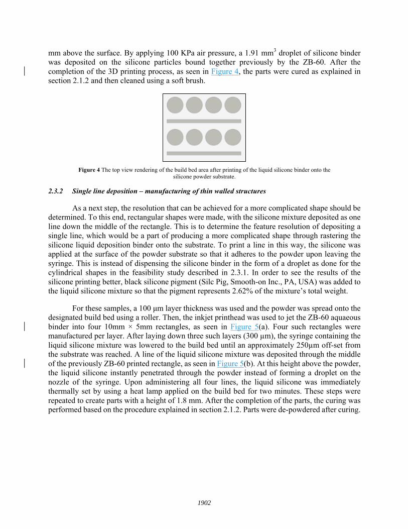
mm above the surface. By applying 100 KPa air pressure, a 1.91 mm3 droplet of silicone binder was deposited on the silicone particles bound together previously by the ZB-60. After the completion of the 3D printing process, as seen in Figure 4, the parts were cured as explained in section 2.1.2 and then cleaned using a soft brush.
Figure 4 The top view rendering of the build bed area after printing of the liquid silicone binder onto the
silicone powder substrate.
2.3.2 Single line deposition – manufacturing of thin walled structures
As a next step, the resolution that can be achieved for a more complicated shape should be determined. To this end, rectangular shapes were made, with the silicone mixture deposited as one line down the middle of the rectangle. This is to determine the feature resolution of depositing a single line, which would be a part of producing a more complicated shape through rastering the silicone liquid deposition binder onto the substrate. To print a line in this way, the silicone was applied at the surface of the powder substrate so that it adheres to the powder upon leaving the syringe. This is instead of dispensing the silicone binder in the form of a droplet as done for the cylindrical shapes in the feasibility study described in 2.3.1. In order to see the results of the silicone printing better, black silicone pigment (Silc Pig, Smooth-on Inc., PA, USA) was added to the liquid silicone mixture so that the pigment represents 2.62% of the mixture’s total weight.
For these samples, a 100 µm layer thickness was used and the powder was spread onto the designated build bed using a roller. Then, the inkjet printhead was used to jet the ZB-60 aquaeous binder into four 10mm × 5mm rectangles, as seen in Figure 5(a). Four such rectangles were manufactured per layer. After laying down three such layers (300 µm), the syringe containing the liquid silicone mixture was lowered to the build bed until an approximately 250µm off-set from the substrate was reached. A line of the liquid silicone mixture was deposited through the middle of the previously ZB-60 printed rectangle, as seen in Figure 5(b). At this height above the powder, the liquid silicone instantly penetrated through the powder instead of forming a droplet on the nozzle of the syringe. Upon administering all four lines, the liquid silicone was immediately thermally set by using a heat lamp applied on the build bed for two minutes. These steps were repeated to create parts with a height of 1.8 mm. After the completion of the parts, the curing was performed based on the procedure explained in section 2.1.2. Parts were de-powdered after curing.
1902
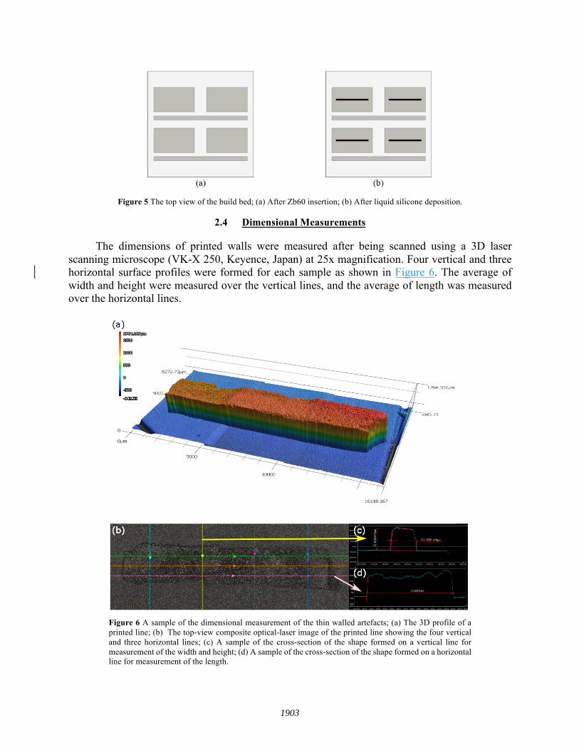
Figure 5 The top view of the build bed; (a) After Zb60 insertion; (b) After liquid silicone deposition.
2.4 Dimensional Measurements
The dimensions of printed walls were measured after being scanned using a 3D laser scanning microscope (VK-X 250, Keyence, Japan) at 25x magnification. Four vertical and three horizontal surface profiles were formed for each sample as shown in Figure 6. The average of width and height were measured over the vertical lines, and the average of length was measured over the horizontal lines.
Figure 6 A sample of the dimensional measurement of the thin walled artefacts; (a) The 3D profile of a printed line; (b) The top-view composite optical-laser image of the printed line showing the four vertical and three horizontal lines; (c) A sample of the cross-section of the shape formed on a vertical line for measurement of the width and height; (d) A sample of the cross-section of the shape formed on a horizontal line for measurement of the length.
1903

2.5 Hardness test
The hardness of the cylindrical samples was measured based on their resistance to the indentation of a shore 00 rigid ball using a handheld durometer (Shore S1, Shore Instruments-Instron, MA, USA). The tests were conducted on the center of three cylinders with a one second dwell time, and repeated three times. Two replication was conducted for this test. A similar test was performed on a cylindrical sample with 3 mm thickness made from the liquid silicone binder.
2.6 CT scanning
The internal micro-structure of the 3D printed cylindrical shapes was investigated using a nano-scale X-ray computed tomography (nanoCT) instrument (Versa 520m, Carl Zeiss AG, Switzerland) at 40kV and 727 nm voxel resolution. In order to isolate both material phases (silicone binder and silicone powder), two threshold values were manually determined as a baseline to separate the more attenuating silicone particles from the less attenuating silicone resin. To account for noise and edge hardening effects, greyscale images were first processed with both bilateral and Gaussian filters. Finally, a local thickness threshold of 14.5 µm was applied to the particle segmentation to prevent brightened surface artifacts on the resin from being considered part of the particle phase.
2.7 Statistical Analysis
An experimental design was formed to investigate the effects of the significant printing parameters on the dimensional accuracy of the printed line features. The goal of the study is minimizing the lateral and vertical dimension of the silicone walls while a minimum deviation between the width and height of the printed feature and the associated CAD model is maintained. DOE is a systematic method for finding the optimum treatment of input factors on the response(s). This statistical approach has been adopted by multiple researchers to improve the printing quality of different AM systems [47-50]. In this experiment, the parameters that can be varied are:
Pressure [kPa] - The pressure applied to the syringe barrel to extrude the liquid silicone binder. Printing velocity [mm/s] - The speed of the syringe as it is depositing the liquid silicone binder. Viscosity [mPa·s] - The viscosity of the liquid silicone binder. Nozzle-substrate offset [mm] - The height of the nozzle above the powder substrate. Intermediate Curing Latency [s] - The amount of time between the deposition of the liquid silicone and the application of the heat lamp for intermediate curing. Intermediate Curing Time [s] - The time span the liquid silicone is kept under the heat lamp. Layer Thickness [µm] - The thickness of the powder rolled on at every iteration. Silicone Deposition Frequency [µm] - The stacked height of layers between depositions of the liquid silicone binder. Final Curing Time [hr] - The amount of time the finished parts will be cured in the furnace.
For this experiment, the effect of the first two parameters, pressure and printing velocity, was investigated, and an optimized value was selected for the other factors using trial and error method. The effect of these two parameters can be effectively quantified using a 22 factorial design experiment. The input parameters as well as their lower and upper levels are summarized in Table 1. Throughout the experiment, all the possible inputs were kept constant. The responses monitored were the width, the height, and the length of the 3D printed features.
1904

factorial design2 2 1Table
Factors Levels
Low (-1) High (+1)
Pressure (KPa) 100 200
Velocity (mm/s) 2 4
In order to compare the hardness of samples printed with different treatment combinations, a
one-way Tukey analysis of variance (ANOVA) at 5% significance level was conducted. Given the fact that all samples were manufactured with the same AM system and under similar conditions, they were supposed to belong to the samples with equal variances. In order to compare the hardness mean values for the 3D printed parts and the molded silicone binder, a Student’s t-test was carried out at 5% significance level. Minitab 17 software package (Minitab Inc., PA, USA) was used for all the statistical analyses.
3 Results and Discussion
3.1 Dimensional Accuracy of Single of the Thin-walled Structures
In order to understand the relationship between the geometrical features of the 3D printed walls and the printing parameters, first-order empirical models were created using DOE. As explained in section 2.7, the effects of printing velocity and pressure on the width, length, and height of the walls were investigated in a 22 factorial design. The details of this factorial design as well as the values measured for each response can be seen in Table 2. Every treatment has been replicated twice in order to minimize the effect of the nuisance factors. The order of manufacturing the thin walls has been completely randomized. The analysis of variance (ANOVA) results for the width, height, and length are summarized in Table 3, Table 4, and Table 5, respectively. These results show that none of the two selected factors have a significant effect on the length and height of the walls at 95% confidence level. However, both parameters and their first-order interaction significantly control the width of the features with the velocity having the highest impact. The Pareto chart for the width (Figure 7) confirms these findings. Also, the residual plots for the width shown in Figure 8 do not show a significant deviation from the underlying assumption of experimental design. As a result, normality, variance consistency, and independency assumptions are valid.
Table 2 Results of the 22 experimental design
Pressure (KPa)
Velocity (mm/s) Replicate Feature Line 1 Line 2 Line 3 Line 4
200 2
1 Width (µm) 4350.086 4283.600 4598.542 4623.759 Height (µm) 2469.783 2464.394 2462.961 2468.649 Length (µm) 14263.147 14135.362 13977.756
2 Width (µm) 3993.010 4109.388 4075.650 4138.439 Height (µm) 1265.081 1267. 614 1221.893 1194.486 Length (µm) 14074.090 14304.194 14680.835
100 4 1 Width (µm) 2333.558 2188.785 2347.014 2411.799 Height (µm) 1845.122 1848.825 1645.594 1549.539 Length (µm) 11894.264 11895.396 11882.259
1905

2 Width (µm) 2562.515 2315.271 2130.472 2281.812 Height (µm) 1537.563 1663.614 1891.989 2163.875 Length (µm) 12455.405 13183.928 13354.432
200 4
1 Width (µm) 2286.078 1996.857 2135.492 2410.971 Height (µm) 2015.417 1638.088 1811.311 2145.714 Length (µm) 11761.958 12301.621 12608.953
2 Width (µm) 2604.057 2442.299 2394.902 2275.519 Height (µm) 1576.744 1930.144 1903.386 2079.480 Length (µm) 14208.509 14208.708 13615.452
100 2
1 Width (µm) 2527.977 2633.382 2589.200 2727.521 Height (µm) 2306.462 2443.082 2382.681 2335.638 Length (µm) 14273.681 14226.147 14071.943
2 Width (µm) 2708.484 2708.503 2325.682 2059.885 Height (µm) 1503.120 1719.369 1889.832 2044.556 Length (µm) 13000.997 13225.835 12756.177
Table 3 ANOVA results for width.
Source DF Adj SS Adj MS F-Value P-Value
Model 3 5363238 1787746 63.32 0.001 Linear 2 3850114 1925057 68.18 0.001 Pressure 1 1502249 1502249 53.21 0.002 Velocity 1 2347865 2347865 83.16 0.001 2-Way Interaction 1 1513124 1513124 53.59 0.002 Pressure×Velocity 1 1513124 1513124 53.59 0.002 Error 4 112935 28234 Total 7 5476173
Table 4 ANOVA results for height.
Source DF Adj SS Adj MS F-Value P-Value
Model 3 102987 34329 0.15 0.926 Linear 2 43300 21650 0.09 0.913 Pressure 1 5721 5721 0.02 0.883 Velocity 1 37579 37579 0.16 0.708 2-Way Interaction 1 59687 59687 0.26 0.639 Pressure×Velocity 1 59687 59687 0.26 0.639 Error 4 927022 231756 Total 7 1030009
Table 5 ANOVA results for length.
Source DF Adj SS Adj MS F-Value P-Value
Model 3 3447755 1149252 1.56 0.331 Linear 2 3447404 1723702 2.34 0.213 Pressure 1 871227 871227 1.18 0.338 Velocity 1 2576178 2576178 3.49 0.135 2-Way Interaction 1 351 351 0 0.984
1906

Pressure×Velocity 1 351 351 0 0.984 Error 4 2950624 737656 Total 7 6398379
Figure 7 Pareto chart for width.
Figure 8 Plot of residuals for width.
The DOE results for the width of the thin walls are in line with the analytical deposition geometry models. The width of an extruded line for a low viscous polymer can be related to the pressure and velocity according to Eq. 1 [45, 51]. Base on this model, the width of the line is
1907

directly proportional to the pressure and inversely proportional to the velocity. A similar conclusion could be made using the regression model fit to the width using DOE (Eq. 2), with pressure having a positive regression coefficient and the velocity a negative coefficient. The accordance of the regression model to the physical rules governing the flow of fluids in the extrusion-based systems along with the high R-squared and adjusted R-squared values (97% and 96%, respectively) for the DOE validate the empirical model. The path of optimization demonstrated in Figure 9 shows that decreasing the pressure value to 100 KPa and increasing the velocity to 4 mm/s results in the line features with the highest resolution. The image of this optimized thin wall as well as its 3D profile is demonstrated in Figure 10.
𝑊𝑖𝑑𝑡ℎ =𝜋𝑅)𝑃8𝜇𝑉ℎ (1)
𝑊𝑖𝑑𝑡ℎ = 2861.6 + 433.3×𝑃 − 541.7×𝑉 − 434.9×𝑃×𝑉 (2)
where 𝑅 is the internal radius of the nozzle, 𝑃 is the pressure, 𝜇 is the viscosity, ℎ is the estimated height of the line feature (the nozzle off-set from the substrate), 𝑉 is the printing velocity.
Curing the silicone binder immediately after dispensing creates a solid barrier, impeding the subsequent infiltration of the liquid silicone binders from the layers above. This solid barrier is the reason behind the constant height of the thin walls for different parameter combinations. The insignificant effect of the input parameters on the length of the features can be traced back to the effect of the overfilling, i.e. depositing more fluid at the start and stop points of the raster, giving a dumbbell shape to the linear features. Also, the perpendicular orientation of the wall length with respect to the roller’s moving direction results in the transferring of the wet powder along the width of the features and not their length. These observations will be more investigated and verified through future experiments.
The optimized resolution achieved in this statistical analysis is approximately 2 mm which is less refined than the standard resolution required for additive manufacturing. The width of the printed line features need to be decreased so that this hybrid system can be used for the production of complex 3D structures. In the future, similar thin walled artefacts will be manufactured using a mixture of the silicone powder and polyvinyl alcohol (PVA). Authors believe that adding PVA to the materials system will improve the geometrical accuracy of the system by preventing the excessive lateral permeation of the silicone resin. A complete thermal analysis of the silicone binder would also help in this regard by determination of the appropriate curing latency and intermediate curing time to prevent lateral spread. Moreover, the current pneumatic micro-syringe system will be replaced by a solenoid drop-on-demand extrusion-system to make a better control of the deposition volume and frequency possible.
1908

Figure 9 2D and 3D contour plots showing the path of optimization; the low level of pressure and high
level of velocity yield the optimized resolution.
Figure 10 The optimized thin walled artefact and its 3D profile manufactured at 100 KPa pressure and 4
mm/s velocity. View of actual part and laser-scanned artefact.
Pressure
Velo
city
200180160140120100
4.0
3.5
3.0
2.5
2.0
> – – – < 2500
2500 30003000 35003500 4000
4000
W
2 00
0510002
0003
0004
23 001
4
W
P erusser
V yticole
1909

3.2 Cylindrical Parts Mechanical Performance
Table 6 summarizes the hardness values measured for both cylindrical additively manufactured parts and the molded and cured silicone binder. The Tukey ANOVA study was carried out to investigate the deviation of samples’ averages from the population average value. The following hypothesis was formed:
§ Null hypothesis: All average values are equal. § Alternative hypothesis: At least one average is different.
The ANOVA test results (Table 7) do not show any statistically significant difference between the average hardness values which represents a uniform manufacturing condition over the building area (P-value: 0.086). The manufacturing conditions have also been kept constant between consecutive printings as the two manufacturing batches have equal average values at 95% confidence level. Moreover, the simultaneous 95% confidence intervals for the average difference of all the samples include zero which confirms the findings of ANOVA.
Table 6 The durometry results for the 3D printed cylinders and molded silicone binder.
Sample Hardness (shore 00)
test 1 test 2 test 3 Average
Cylinder 1 (batch 1) 80.5 85.6 80.9 82.33
Cylinder 2 (batch 1) 87.3 85.2 82.8 85.10
Cylinder 3 (batch 1) 80.7 80.1 81.5 80.77
Cylinder 1 (batch 2) 81.5 85.3 86 84.27
Cylinder 2 (batch 2) 85.3 84.3 85.2 84.93
Cylinder 3 (batch 2) 80.9 87.8 84.7 84.47
Total average for cylindrical samples 83.64
Molded silicone binder 1 81.5 80.1 75.4 79.00
Molded silicone binder 2 81.2 81.2 79.6 80.67
Total average for molded silicone binder 79.83
Table 7 ANOVA results for the hardness test.
Source DF Adj SS Adj MS F-Value P-Value
Measurements 5 55.49 11.098 2.54 0.086
Error 12 52.47 4.373
Total 17 107.96
1910
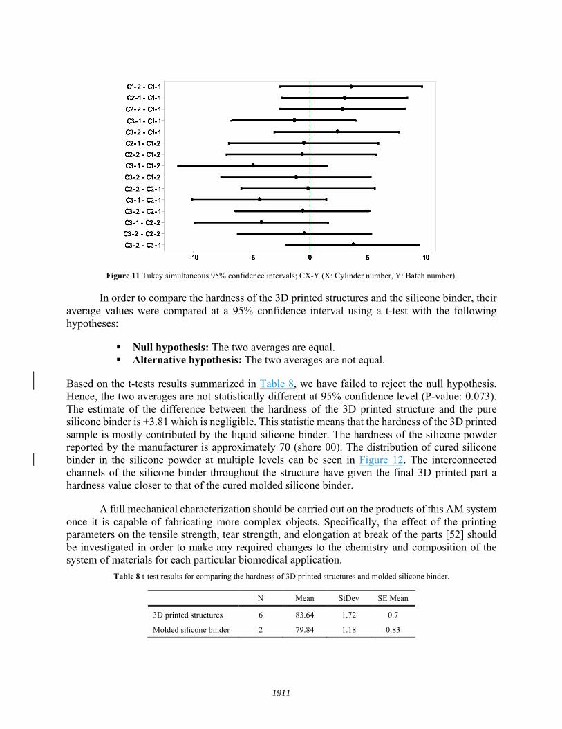
Figure 11 Tukey simultaneous 95% confidence intervals; CX-Y (X: Cylinder number, Y: Batch number).
In order to compare the hardness of the 3D printed structures and the silicone binder, their average values were compared at a 95% confidence interval using a t-test with the following hypotheses:
§ Null hypothesis: The two averages are equal. § Alternative hypothesis: The two averages are not equal.
Based on the t-tests results summarized in Table 8, we have failed to reject the null hypothesis. Hence, the two averages are not statistically different at 95% confidence level (P-value: 0.073). The estimate of the difference between the hardness of the 3D printed structure and the pure silicone binder is +3.81 which is negligible. This statistic means that the hardness of the 3D printed sample is mostly contributed by the liquid silicone binder. The hardness of the silicone powder reported by the manufacturer is approximately 70 (shore 00). The distribution of cured silicone binder in the silicone powder at multiple levels can be seen in Figure 12. The interconnected channels of the silicone binder throughout the structure have given the final 3D printed part a hardness value closer to that of the cured molded silicone binder.
A full mechanical characterization should be carried out on the products of this AM system once it is capable of fabricating more complex objects. Specifically, the effect of the printing parameters on the tensile strength, tear strength, and elongation at break of the parts [52] should be investigated in order to make any required changes to the chemistry and composition of the system of materials for each particular biomedical application.
Table 8 t-test results for comparing the hardness of 3D printed structures and molded silicone binder.
N Mean StDev SE Mean
3D printed structures 6 83.64 1.72 0.7
Molded silicone binder 2 79.84 1.18 0.83
1911

Figure 12 The CT scan results at 727 nm voxel size; (a) The cylindrical shape and its 3D profile; (b) The
3D view of a small portion of the 3D printed structure; (c) a top view cross-section of the part near the surface; (d) a top view cross-section of the part at the center of the structure. (c-d) The blue, yellow, and
black areas correspond to the cured silicone binder, silicone powder, and air respectively.
4 Conclusion
In this study, a novel hybrid PBBJ and micro-dispensing technique for the production of structures made from silicone powder and liquid silicone rubber at a proof-of-concept stage was introduced. Even though a sole PBBJ system could be much faster than the hybrid system, binding the silicone powder particles using the micro-dispense technique is necessary because current thermal and piezoelectric jetting systems are not compatible with high viscous silicone binders, specifically with thermosets. The method was successfully employed for the manufacturing of simple geometries such as cylinders and thin walls. The manufactured parts demonstrated enough resilience and hardness (approximately 80 shore 00) to be used for different biomedical applications. However, more mechanical characterization is required for future applications. Furthermore, the porous structure achieved can be altered for the fabrication of drug-delivery parts with controlled drug release rates.
1912

The designed experiment resulted in a validated regression model for controlling the width of the printed line features. The current lateral resolution of more than 2 mm also revealed that a thermal analysis of the silicone binder as well as modifications to the powder system and the AM set up are required to control the dimensions of the final products and achieve the geometrically accurate parts. These changes should be made in the future so that complex structures can be printed using this hybrid AM technique. To take advantage of all the benefits of the PBBJ system, trials for developing a system based on the direct jetting of silicone binder should be continued at the same time.
Acknowledgment
The authors appreciate the funding support received from The Natural Sciences and Engineering Research Council of Canada (NSERC), grant #50503-10713. Furthermore, the authors would like to acknowledge the work of research interns Abhinav Grover and Alysan Young in developing printing recipes for the silicone material systems.
5 References
[1] Noll W. Chemistry and technology of silicones: Elsevier. 2012
[2] Butler DF, Gion GG, Rapini RP. Silicone auricular prosthesis. Journal of the American Academy of Dermatology 2000; 43: 687-690
[3] In E, Walker E, Naguib H. Novel Development of 3D printable UV-curable Silicone for Multimodal Imaging Phantom. Bioprinting 2017
[4] Schüler R, Wittkampf M, Chemnitius G. Modified gas-permeable silicone rubber membranes for covalent immobilisation of enzymes and their use in biosensor development. Analyst 1999; 124: 1181-1184
[5] Ren J, Wang L, Han X, Cheng J, Lv H, Wang J, Jian X, Zhao M, Jia L. Organic Silicone Sol–Gel Polymer as a Noncovalent Carrier of Receptor Proteins for Label-Free Optical Biosensor Application. ACS applied materials & interfaces 2012; 5: 386-394
[6] Golomb G, Dixon M, Smith MS, Schoen FJ, Levy RJ. Controlled- release drug delivery of diphosphonates to inhibit bioprosthetic heart valve calcification: Release rate modulation with silicone matrices via drug solubility and membrane coating. Journal of pharmaceutical sciences 1987; 76: 271-276
[7] Au AK, Lee W, Folch A. Mail-order microfluidics: evaluation of stereolithography for the production of microfluidic devices. Lab on a Chip 2014; 14: 1294-1301
[8] Eggbeer D, Bibb R, Evans P, Ji L. Evaluation of direct and indirect additive manufacture of maxillofacial prostheses. Proceedings of the Institution of Mechanical Engineers.Part H, Journal of engineering in medicine 2012; 226: 718-728
1913
[9] Xiao K, Zardawi F, van Noort R, Yates JM. Developing a 3D colour image reproduction system for additive manufacturing of facial prostheses. The International Journal of Advanced Manufacturing Technology 2014; 70: 2043-2049
[10] Zardawi FM, Xiao K, Van Noort R, Yates JM. Investigation of Elastomer Infiltration into 3D Printed Facial Soft Tissue Prostheses. Anaplastology 2015; 2015
[11] Bibb R, Eggbeer D, Evans P. Rapid prototyping technologies in soft tissue facial prosthetics: current state of the art. Rapid Prototyping Journal 2010; 16: 130-137
[12] Bai S, Feng Z, Gao R, Dong Y, Bi Y, Wu G, Chen X. Development and application of a rapid rehabilitation system for reconstruction of maxillofacial soft-tissue defects related to war and traumatic injuries. Military Medical Research 2014; 1: 11
[13] Kojima T. Salivary Gland Development and Regeneration. In: Regenerative Medicine in Otolaryngology: Springer. 2015: 209-223
[14] Mannoor MS, Jiang Z, James T, Kong YL, Malatesta KA, Soboyejo WO, Verma N, Gracias DH, McAlpine MC. 3D printed bionic ears. Nano letters 2013; 13: 2634-2639
[15] Duoss EB, Weisgraber TH, Hearon K, Zhu C, Small W, Metz TR, Vericella JJ, Barth HD, Kuntz JD, Maxwell RS. Three-dimensional printing of elastomeric, cellular architectures with negative stiffness. Advanced Functional Materials 2014; 24: 4905-4913
[16] Liravi F, Darleux R, Toyserkani E. Nozzle dispensing additive manufacturing of polysiloxane: dimensional control. International Journal of Rapid Manufacturing 2015; 5: 20-43
[17] Kolesky DB, Truby RL, Gladman A, Busbee TA, Homan KA, Lewis JA. 3D bioprinting of vascularized, heterogeneous cell-laden tissue constructs. Advanced Materials 2014; 26: 3124-3130
[18] Kolesky DB, Homan KA, Skylar-Scott MA, Lewis JA. Three-dimensional bioprinting of thick vascularized tissues. Proceedings of the National Academy of Sciences of the United States of America 2016; 113: 3179-3184
[19] Tian K, Bae J, Bakarich SE, Yang C, Gately RD, Spinks GM, Suo Z, Vlassak JJ. 3D Printing of Transparent and Conductive Heterogeneous Hydrogel–Elastomer Systems. Advanced Materials 2017
[20] Schmalzer AM, Cady CM, Geller D, Ortiz-Acosta D, Zocco AT, Stull J, Labouriau A. Gamma radiation effects on siloxane-based additive manufactured structures. Radiation Physics and Chemistry 2017; 130: 103-111
[21] Murphy SV, Atala A. 3D bioprinting of tissues and organs. Nature biotechnology 2014; 32: 773-785
1914
[22] Chang CC, Boland ED, Williams SK, Hoying JB. Direct-write bioprinting three-dimensional biohybrid systems for future regenerative therapies. Journal of Biomedical Materials Research Part B: Applied Biomaterials 2011; 98: 160-170
[23] Hinton TJ, Hudson AR, Pusch K, Lee A, Feinberg AW. 3D Printing PDMS Elastomer in a Hydrophilic Support Bath via Freeform Reversible Embedding. ACS Biomaterials Science & Engineering 2016
[24] Fripp Design and Research. Fripp Design and Research
[25] Kim DSD, Tai BL. Hydrostatic support-free fabrication of three-dimensional soft structures. Journal of Manufacturing Processes 2016
[26] Kim DSD, Thompson S, Grunlan M, Tai BL. Optimization of Low One-photon Polymerization for Hydrostatic 3D Printing of Silicone Material
[27] Reitelshöfer S, Göttler M, Schmidt P, Treffer P, Landgraf M, Franke J. Aerosol-Jet-Printing silicone layers and electrodes for stacked dielectric elastomer actuators in one processing device 2016: 97981Y-97981Y-9
[28] Sachs EM, Haggerty JS, Cima MJ, Williams PA. . Three-dimensional printing techniques 1993
[29] Gibson I, Rosen DW, Stucker B. Additive manufacturing technologies: Springer. 2010
[30] Hong SB, Eliaz N, Leisk GG, Sach EM, Latanision RM, Allen SM. A new Ti-5Ag alloy for customized prostheses by three-dimensional printing (3DP). Journal of dental research 2001; 80: 860-863
[31] Shanjani Y, Hu Y, Pilliar RM, Toyserkani E. Mechanical characteristics of solid-freeform-fabricated porous calcium polyphosphate structures with oriented stacked layers. Acta biomaterialia 2011; 7: 1788-1796
[32] Habibovic P, Gbureck U, Doillon CJ, Bassett DC, van Blitterswijk CA, Barralet JE. Osteoconduction and osteoinduction of low-temperature 3D printed bioceramic implants. Biomaterials 2008; 29: 944-953
[33] Gbureck U, Vorndran E, Müller FA, Barralet JE. Low temperature direct 3D printed bioceramics and biocomposites as drug release matrices. Journal of Controlled Release 2007; 122: 173-180
[34] Khalyfa A, Vogt S, Weisser J, Grimm G, Rechtenbach A, Meyer W, Schnabelrauch M. Development of a new calcium phosphate powder-binder system for the 3D printing of patient specific implants. Journal of Materials Science: Materials in Medicine 2007; 18: 909-916
1915

[35] Igawa K, Mochizuki M, Sugimori O, Shimizu K, Yamazawa K, Kawaguchi H, Nakamura K, Takato T, Nishimura R, Suzuki S. Tailor-made tricalcium phosphate bone implant directly fabricated by a three-dimensional ink-jet printer. Journal of Artificial Organs 2006; 9: 234-240
[36] Vlasea M, Toyserkani E, Pilliar R. Effect of gray scale binder levels on additive manufacturing of porous scaffolds with heterogeneous properties. International Journal of Applied Ceramic Technology 2015; 12: 62-70
[37] Stevens B, Yang Y, Mohandas A, Stucker B, Nguyen KT. A review of materials, fabrication methods, and strategies used to enhance bone regeneration in engineered bone tissues. Journal of biomedical materials research Part B: applied biomaterials 2008; 85: 573-582
[38] Hutmacher DW, Sittinger M, Risbud MV. Scaffold-based tissue engineering: rationale for computer-aided design and solid free-form fabrication systems. Trends in biotechnology 2004; 22: 354-362
[39] Hutmacher DW. Scaffolds in tissue engineering bone and cartilage. Biomaterials 2000; 21: 2529-2543
[40] Castilho M, Dias M, Gbureck U, Groll J, Fernandes P, Pires I, Gouveia B, Rodrigues J, Vorndran E. Fabrication of computationally designed scaffolds by low temperature 3D printing. Biofabrication 2013; 5: 035012
[41] Hollister SJ. Porous scaffold design for tissue engineering. Nature materials 2005; 4: 518-524
[42] Szucs TD, Brabazon D. Analysis of the effects of 3DP parameters on part feature dimensional accuracy 2007
[43] Warnke PH, Seitz H, Warnke F, Becker ST, Sivananthan S, Sherry E, Liu Q, Wiltfang J, Douglas T. Ceramic scaffolds produced by computer-assisted 3D printing and sintering: Characterization and biocompatibility investigations. Journal of Biomedical Materials Research Part B: Applied Biomaterials 2010; 93: 212-217
[44] Zardawi FM. Characterisation of Implant Supported Soft Tissue Prostheses Produced with 3D Colour Printing Technology 2013
[45] Vlasea M, Toyserkani E. Experimental characterization and numerical modeling of a micro-syringe deposition system for dispensing sacrificial photopolymers on particulate ceramic substrates. Journal of Materials Processing Technology 2013; 213: 1970-1977
[46] Toyserkani E, VLASEA M, SHANJANI Y. Systems and methods for additive manufacturing of heterogeneous porous structures and structures made therefrom 2014
1916

[47] Brandl E, Heckenberger U, Holzinger V, Buchbinder D. Additive manufactured AlSi10Mg samples using Selective Laser Melting (SLM): Microstructure, high cycle fatigue, and fracture behavior. Materials & Design 2012; 34: 159-169
[48] Kechagias J. Investigation of LOM process quality using design of experiments approach. Rapid Prototyping Journal 2007; 13: 316-323
[49] Liao H, Shie J. Optimization on selective laser sintering of metallic powder via design of experiments method. Rapid Prototyping Journal 2007; 13: 156-162
[50] Oh JH, Lim SY. Precise size control of inkjet-printed droplets on a flexible polymer substrate using plasma surface treatment. Journal of Micromechanics and Microengineering 2010; 20: 015030
[51] Vozzi G, Previti A, De Rossi D, Ahluwalia A. Microsyringe-based deposition of two-dimensional and three-dimensional polymer scaffolds with a well-defined geometry for application to tissue engineering. Tissue engineering 2002; 8: 1089-1098
[52] Aziz T, Waters M, Jagger R. Analysis of the properties of silicone rubber maxillofacial prosthetic materials. Journal of dentistry 2003; 31: 67-74
1917