A Homeowners Guide: Installing a Septic Tank and Drainfield · Introduction This guidance is...
23
A Homeowners Guide: Installing a Septic Tank and Drainfield NMED Liquid Waste Program Public Outreach and Training October 2006 Homeowner’s Manual 2006
Transcript of A Homeowners Guide: Installing a Septic Tank and Drainfield · Introduction This guidance is...
A Homeowners Guide: Installing a Septic Tank and Drainfield
NMED Liquid Waste Program Public Outreach and Training
October 2006
Homeowner’s Manual 2006

Credits: This program was originally developed by:
Adrian Hanson, Ph.D., PE: NMSU/Tejeda Center Craig Runyan: NMSU/Agricultural Extension Specialist
Bruce Lesikar: Texas A&M/Agricultural Extension Specialist
NMED Surface Water Bureau Non-point Pollution Discharge Control Program
May 2003
Funding For this Project Has Been Provided By
EPA 305h Grant
Frank M. Tejeda Center USDA Rio Project NM Border Health
WERC/DOE
Homeowner’s Manual 2006
II
Table of Contents Topic Page Introduction 1
Overview of the System 1 Permit Information 2
Preliminary Site Check 3 Installation 6
Pipe from House to Tank 6 Estimating Pipe Drop From House to Septic Tank 7
Concrete Tank 8 Plastic Tank 11 Drainfield 12
Pipe and Gravel System 14 Chamber Systems 15
Appendix I: Septic Tank Permit Application Form Appendix II: Contact Information for Assistance
Homeowner’s Manual 2006
III
Introduction This guidance is restricted to the Homeowner installing a conventional septic tank and drainfield system for their primary residence. It is also restricted to system receiving less than 2000 gallons/day and no more than 500 gallon/day/acre of liquid waste. An onsite wastewater permit is required to install or modify your own on-site wastewater treatment system. You are only allowed to install your own system. The permit application for installation or modification of a system is included in Appendix I. This is only the New Mexico Liquid Waste Disposal Permit Application Form (septic tank permit). Along with this form you may be asked to submit any or all of the various pieces of information discussed in Section 402 of the Liquid Waste Disposal and Treatment Regulation. The appendix does not include potential supporting permits and paperwork such as building permit, utility permit, etc. Working through this workbook should allow you to satisfy the State permitting requirements for a simple onsite wastewater treatment system and provide you with insight on the design and installation criteria. Overview of the System An onsite wastewater treatment system is an efficient means of disposing of household waste. The conventional septic system when properly installed and maintained is an effective means of separating solid waste and removing pathogens. Wastewater from the home contains fecal matter, impurities and pathogens. Pathogens are disease organisms that can cause severe illness or even death. Contamination from an improperly installed or poorly maintained system can be carried to the water table or can erupt at the surface. A contaminated water supply could cause the property to be uninhabitable. Water treatment to remove pathogens can easily cost more than the most advanced wastewater treatment units. Surfacing wastewater will expose your family to pathogens through direct contact, insects, even the family pets. People most impacted by wastewater contamination are the young, the elderly, and persons with reduced immune capacity. A conventional onsite wastewater treatment system consists of a two-chamber treatment tank and a drainfield or leachfield. The treatment tank separates the material that will either float or sink. This separated material is held in the tank and partially eaten by anaerobic (do not require oxygen) bacteria. Pathogens are somewhat reduced in the treatment tank, but the reduction is too little to make the water safe for direct contact. After separation and settling in the treatment tank, the effluent flows to the drainfield. The drainfield disperses the effluent into an area of soil where it is further treated and disposed of. The soil under the drainfield has air spaces in it and pathogens are quickly destroyed by areobic (require oxygen) bacteria native to the soil. In a drainfield that is functioning properly, the pathogens are mostly destroyed within 12 inches of the trench bottom. If the system is overloaded, the soils can become anaerobic and plug. This reduces the efficiency of the system for killing pathogens and may cause the system to backup and partially treated wastewater will rise to the surface or possibly enter the home. It is important that the system be sized properly, constructed properly, and
Homeowner’s Manual 2006
1
maintained properly. Proper maintenance requires that the system be periodically inspected and pumped when required so that the solids being held in the tank will not overfill the tank and wash into the drainfield. Some jurisdictions may have required schedules for inspection and pumping, if not, plan for it, it is vital to the proper operation of your system. When scum and sludge make up 25-35% of the vertical column in the inlet chamber, the tank must be pumped! This handbook will assist you in sizing and constructing your system.
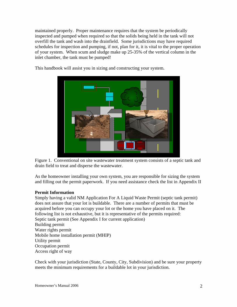
Figure 1. Conventional on site wastewater treatment system consists of a septic tank and drain field to treat and disperse the wastewater. As the homeowner installing your own system, you are responsible for sizing the system and filling out the permit paperwork. If you need assistance check the list in Appendix II Permit Information Simply having a valid NM Application For A Liquid Waste Permit (septic tank permit) does not assure that your lot is buildable. There are a number of permits that must be acquired before you can occupy your lot or the home you have placed on it. The following list is not exhaustive, but it is representative of the permits required: Septic tank permit (See Appendix I for current application) Building permit Water rights permit Mobile home installation permit (MHIP) Utility permit Occupation permit Access right of way Check with your jurisdiction (State, County, City, Subdivision) and be sure your property meets the minimum requirements for a buildable lot in your jurisdiction.
Homeowner’s Manual 2006
2
Your Permit Application is in Appendix I. These instructions will take you through sizing your septic tank and drainfield. However, before you go through the process of filling out your permit application, you may want to perform a preliminary check to see if your lot appears to be large enough for a conventional septic tank and drainfield system. Preliminary Site Check There are several issues to be considered prior to designing an onsite wastewater system for your lot. You must consider lot size, setbacks, distance to limiting soil features, access for maintenance and area for future replacement.
1) With few exceptions your lot must be at least 3/4 of an acre. The lot size information will be on your lot plat, or on your survey if it is a separate document.
2) Layout a typical system on your plat map and see if your system meets the required setbacks of Table 302.1 (illustrated in Figure 2).
3) Working with the officials in your area, determine the probable depth to the seasonal high water table or limiting soil layer. The water level in nearby wells (usually contained in well logs), or if necessary, test holes, may help determine the depth to groundwater and types of soil present. If groundwater is shallow (less than 10-20 feet), the seasonal high water table may be a limiting condition, and more a more exact determination must be made. There must be at least 4 feet between the bottom of the drain field and the limiting feature at your site:
o High ground water table o Bedrock o Impervious layer (Clay or Caliches layer)
4) Will maintenance personnel and equipment have access to the system from your property? Pumper trucks are large and have significant weight. Heavy equipment can not be routed over any part of your system.
Homeowner’s Manual 2006
3
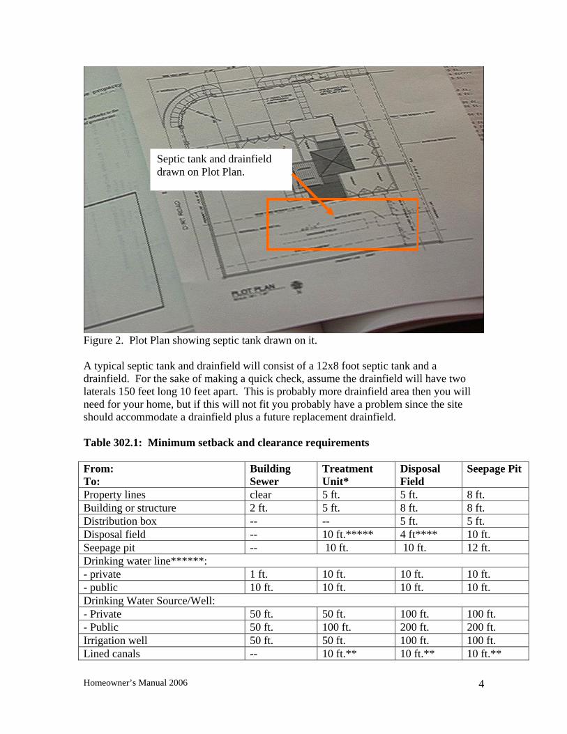
Septic tank and drainfield drawn on Plot Plan.
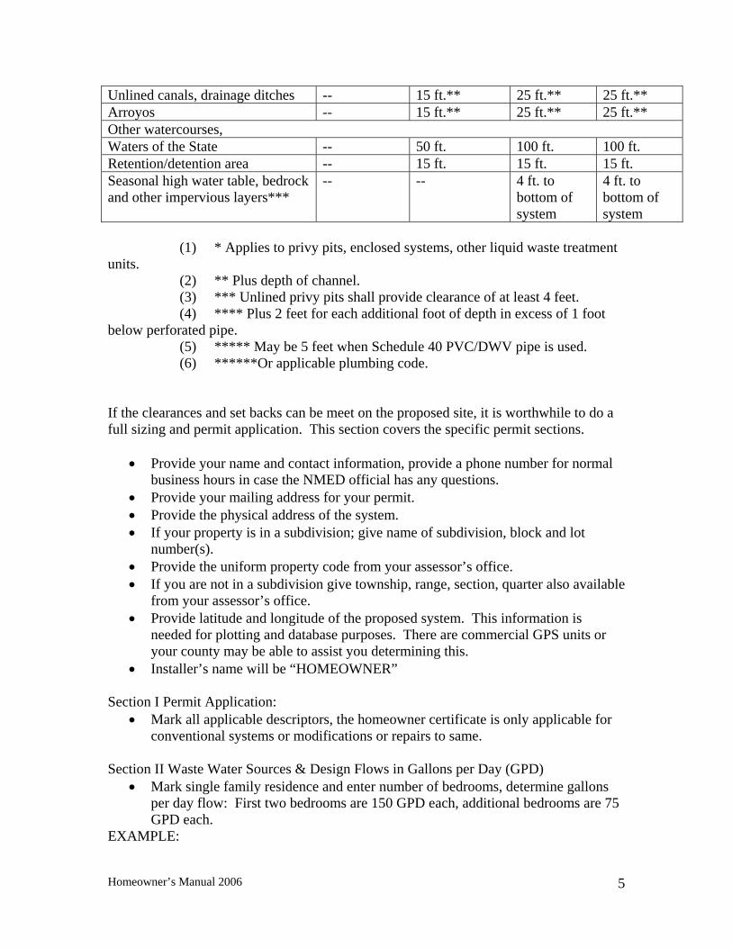
Figure 2. Plot Plan showing septic tank drawn on it. A typical septic tank and drainfield will consist of a 12x8 foot septic tank and a drainfield. For the sake of making a quick check, assume the drainfield will have two laterals 150 feet long 10 feet apart. This is probably more drainfield area then you will need for your home, but if this will not fit you probably have a problem since the site should accommodate a drainfield plus a future replacement drainfield. Table 302.1: Minimum setback and clearance requirements From: To:
Building Sewer
Treatment Unit*
Disposal Field
Seepage Pit
Property lines clear 5 ft. 5 ft. 8 ft. Building or structure 2 ft. 5 ft. 8 ft. 8 ft. Distribution box -- -- 5 ft. 5 ft. Disposal field -- 10 ft.***** 4 ft**** 10 ft. Seepage pit -- 10 ft. 10 ft. 12 ft. Drinking water line******: - private 1 ft. 10 ft. 10 ft. 10 ft. - public 10 ft. 10 ft. 10 ft. 10 ft. Drinking Water Source/Well: - Private 50 ft. 50 ft. 100 ft. 100 ft. - Public 50 ft. 100 ft. 200 ft. 200 ft. Irrigation well 50 ft. 50 ft. 100 ft. 100 ft. Lined canals -- 10 ft.** 10 ft.** 10 ft.**
Homeowner’s Manual 2006
4
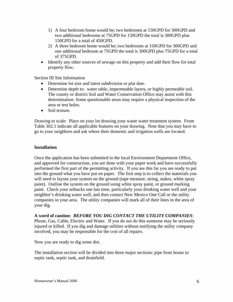
Unlined canals, drainage ditches -- 15 ft.** 25 ft.** 25 ft.** Arroyos -- 15 ft.** 25 ft.** 25 ft.** Other watercourses, Waters of the State -- 50 ft. 100 ft. 100 ft. Retention/detention area -- 15 ft. 15 ft. 15 ft. Seasonal high water table, bedrock and other impervious layers***
-- -- 4 ft. to bottom of system
4 ft. to bottom of system
(1) * Applies to privy pits, enclosed systems, other liquid waste treatment units. (2) ** Plus depth of channel. (3) *** Unlined privy pits shall provide clearance of at least 4 feet. (4) **** Plus 2 feet for each additional foot of depth in excess of 1 foot below perforated pipe. (5) ***** May be 5 feet when Schedule 40 PVC/DWV pipe is used. (6) ******Or applicable plumbing code. If the clearances and set backs can be meet on the proposed site, it is worthwhile to do a full sizing and permit application. This section covers the specific permit sections.
• Provide your name and contact information, provide a phone number for normal business hours in case the NMED official has any questions.
• Provide your mailing address for your permit. • Provide the physical address of the system. • If your property is in a subdivision; give name of subdivision, block and lot
number(s). • Provide the uniform property code from your assessor’s office. • If you are not in a subdivision give township, range, section, quarter also available
from your assessor’s office. • Provide latitude and longitude of the proposed system. This information is
needed for plotting and database purposes. There are commercial GPS units or your county may be able to assist you determining this.
• Installer’s name will be “HOMEOWNER” Section I Permit Application:
• Mark all applicable descriptors, the homeowner certificate is only applicable for conventional systems or modifications or repairs to same.
Section II Waste Water Sources & Design Flows in Gallons per Day (GPD)
• Mark single family residence and enter number of bedrooms, determine gallons per day flow: First two bedrooms are 150 GPD each, additional bedrooms are 75 GPD each.
EXAMPLE:
Homeowner’s Manual 2006
5
1) A four bedroom home would be; two bedrooms at 150GPD for 300GPD and two additional bedrooms at 75GPD for 150GPD the total is 300GPD plus 150GPD for a total of 450GPD.
2) A three bedroom home would be; two bedrooms at 150GPD for 300GPD and one additional bedroom at 75GPD the total is 300GPD plus 75GPD for a total of 375GPD.
• Identify any other sources of sewage on this property and add their flow for total property flow.
Section III Site Information
• Determine lot size and latest subdivision or plat date. • Determine depth to: water table, impermeable layers, or highly permeable soil.
The county or district Soil and Water Conservation Office may assist with this determination. Some questionable areas may require a physical inspection of the area or test holes.
• Soil texture. Drawing to scale: Place on your lot drawing your waste water treatment system. From Table 302.1 indicate all applicable features on your drawing. Note that you may have to go to your neighbors and ask where their domestic and irrigation wells are located. Installation Once the application has been submitted to the local Environment Department Office, and approved for construction, you are done with your paper work and have successfully performed the first part of the permitting activity. If you are this far you are ready to put into the ground what you have put on paper. The first step is to collect the materials you will need to layout your system on the ground (tape measure, string, stakes, white spray paint). Outline the system on the ground using white spray paint, or ground marking paint. Check your setbacks one last time, particularly your drinking water well and your neighbor’s drinking water well, and then contact New Mexico One Call or the utility companies in your area. The utility companies will mark all of their lines in the area of your dig. A word of caution: BEFORE YOU DIG CONTACT THE UTILITY COMPANIES: Phone, Gas, Cable, Electric and Water. If you do not do this someone may be seriously injured or killed. If you dig and damage utilities without notifying the utility company involved, you may be responsible for the cost of all repairs. Now you are ready to dig some dirt. The installation section will be divided into three major sections: pipe from house to septic tank, septic tank, and drainfield.
Homeowner’s Manual 2006
6
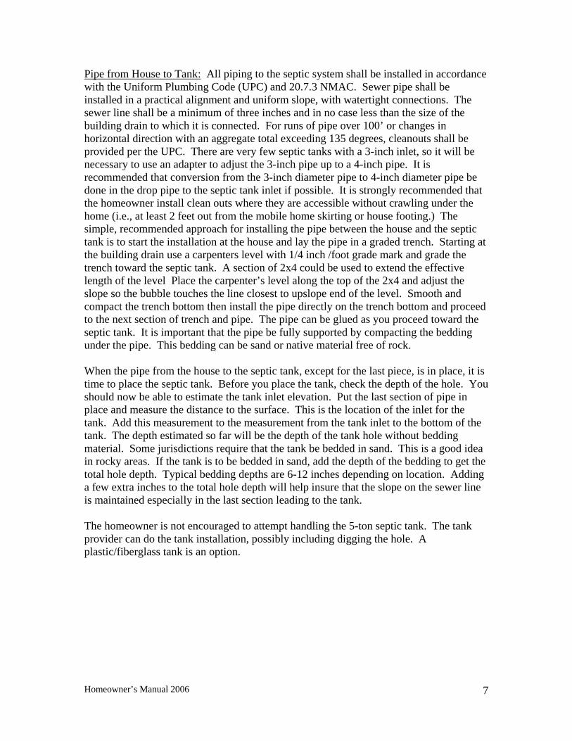
Pipe from House to Tank: All piping to the septic system shall be installed in accordance with the Uniform Plumbing Code (UPC) and 20.7.3 NMAC. Sewer pipe shall be installed in a practical alignment and uniform slope, with watertight connections. The sewer line shall be a minimum of three inches and in no case less than the size of the building drain to which it is connected. For runs of pipe over 100’ or changes in horizontal direction with an aggregate total exceeding 135 degrees, cleanouts shall be provided per the UPC. There are very few septic tanks with a 3-inch inlet, so it will be necessary to use an adapter to adjust the 3-inch pipe up to a 4-inch pipe. It is recommended that conversion from the 3-inch diameter pipe to 4-inch diameter pipe be done in the drop pipe to the septic tank inlet if possible. It is strongly recommended that the homeowner install clean outs where they are accessible without crawling under the home (i.e., at least 2 feet out from the mobile home skirting or house footing.) The simple, recommended approach for installing the pipe between the house and the septic tank is to start the installation at the house and lay the pipe in a graded trench. Starting at the building drain use a carpenters level with 1/4 inch /foot grade mark and grade the trench toward the septic tank. A section of 2x4 could be used to extend the effective length of the level Place the carpenter’s level along the top of the 2x4 and adjust the slope so the bubble touches the line closest to upslope end of the level. Smooth and compact the trench bottom then install the pipe directly on the trench bottom and proceed to the next section of trench and pipe. The pipe can be glued as you proceed toward the septic tank. It is important that the pipe be fully supported by compacting the bedding under the pipe. This bedding can be sand or native material free of rock. When the pipe from the house to the septic tank, except for the last piece, is in place, it is time to place the septic tank. Before you place the tank, check the depth of the hole. You should now be able to estimate the tank inlet elevation. Put the last section of pipe in place and measure the distance to the surface. This is the location of the inlet for the tank. Add this measurement to the measurement from the tank inlet to the bottom of the tank. The depth estimated so far will be the depth of the tank hole without bedding material. Some jurisdictions require that the tank be bedded in sand. This is a good idea in rocky areas. If the tank is to be bedded in sand, add the depth of the bedding to get the total hole depth. Typical bedding depths are 6-12 inches depending on location. Adding a few extra inches to the total hole depth will help insure that the slope on the sewer line is maintained especially in the last section leading to the tank. The homeowner is not encouraged to attempt handling the 5-ton septic tank. The tank provider can do the tank installation, possibly including digging the hole. A plastic/fiberglass tank is an option.
Homeowner’s Manual 2006
7
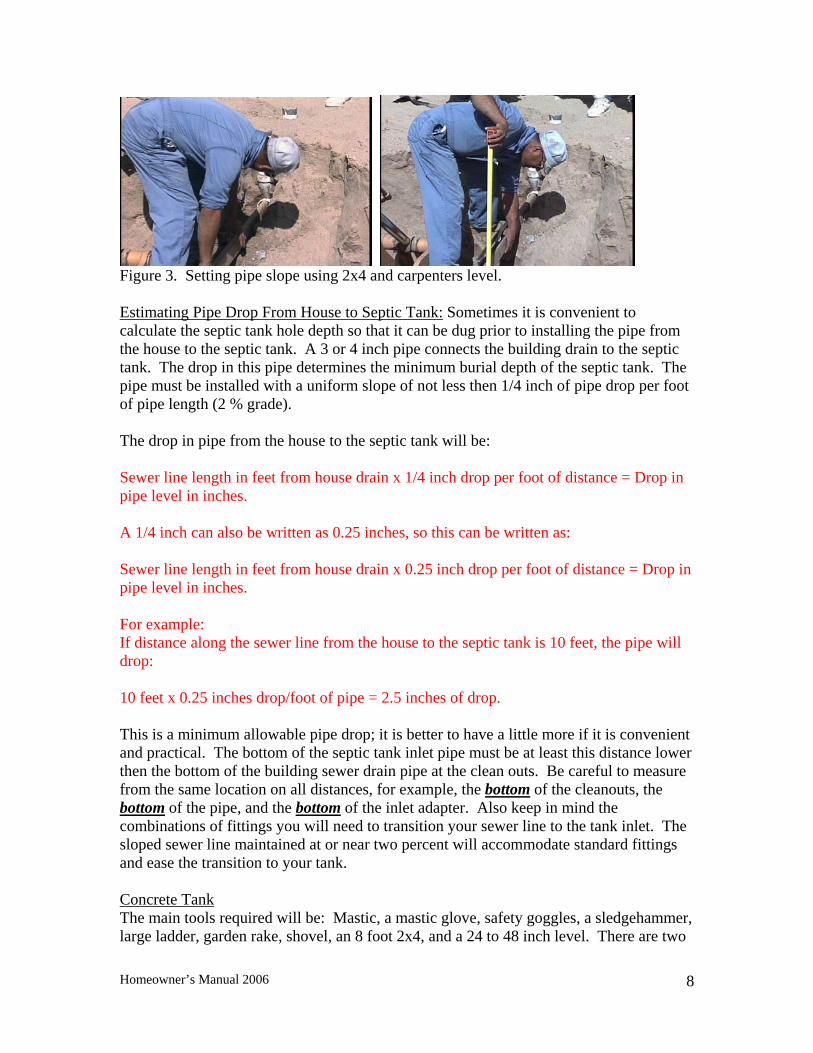
Figure 3. Setting pipe slope using 2x4 and carpenters level. Estimating Pipe Drop From House to Septic Tank: Sometimes it is convenient to calculate the septic tank hole depth so that it can be dug prior to installing the pipe from the house to the septic tank. A 3 or 4 inch pipe connects the building drain to the septic tank. The drop in this pipe determines the minimum burial depth of the septic tank. The pipe must be installed with a uniform slope of not less then 1/4 inch of pipe drop per foot of pipe length (2 % grade). The drop in pipe from the house to the septic tank will be: Sewer line length in feet from house drain x 1/4 inch drop per foot of distance = Drop in pipe level in inches. A 1/4 inch can also be written as 0.25 inches, so this can be written as: Sewer line length in feet from house drain x 0.25 inch drop per foot of distance = Drop in pipe level in inches. For example: If distance along the sewer line from the house to the septic tank is 10 feet, the pipe will drop: 10 feet x 0.25 inches drop/foot of pipe = 2.5 inches of drop. This is a minimum allowable pipe drop; it is better to have a little more if it is convenient and practical. The bottom of the septic tank inlet pipe must be at least this distance lower then the bottom of the building sewer drain pipe at the clean outs. Be careful to measure from the same location on all distances, for example, the bottom of the cleanouts, the bottom of the pipe, and the bottom of the inlet adapter. Also keep in mind the combinations of fittings you will need to transition your sewer line to the tank inlet. The sloped sewer line maintained at or near two percent will accommodate standard fittings and ease the transition to your tank. Concrete Tank The main tools required will be: Mastic, a mastic glove, safety goggles, a sledgehammer, large ladder, garden rake, shovel, an 8 foot 2x4, and a 24 to 48 inch level. There are two
Homeowner’s Manual 2006
8
common types of septic tanks, reinforced concrete and plastic/fiberglass. Regardless of the type of tank being installed digging the hole is the same. The hole should be two feet larger then the septic tank being placed into the hole. This measurement is for the bottom of the hole not the top, since the sides of the hole are seldom straight up and down. It is noted that the having the sides of the hole as nearly vertical as possible is desirable. It reduces the amount of material to be handled and allows the equipment placing the tank to get closer to the work. A word of caution: Digging a large hole in loose or sandy soil may be dangerous. Be careful and use good judgment, the sides of the hole may need to be supported. And have an observer onsite while working in the hole. The depth of the hole for the septic tank is the depth of the house drain plus the drop in the pipe required for the water to flow from the house to the septic tank, plus the depth of the tank, plus the depth of the bedding to be used minus the slope of the ground. After you dig the hole for the septic tank, before placing the tank in the hole, remove all large rocks from the bottom of the hole and carefully level the bottom of the hole. The septic tank hole is leveled, as shown in Figure 4, using an eight-foot 2x4 and a carpenter’s level. DO NOT place a 5-ton reinforced concrete tank yourself. This should be left to the tank provider.
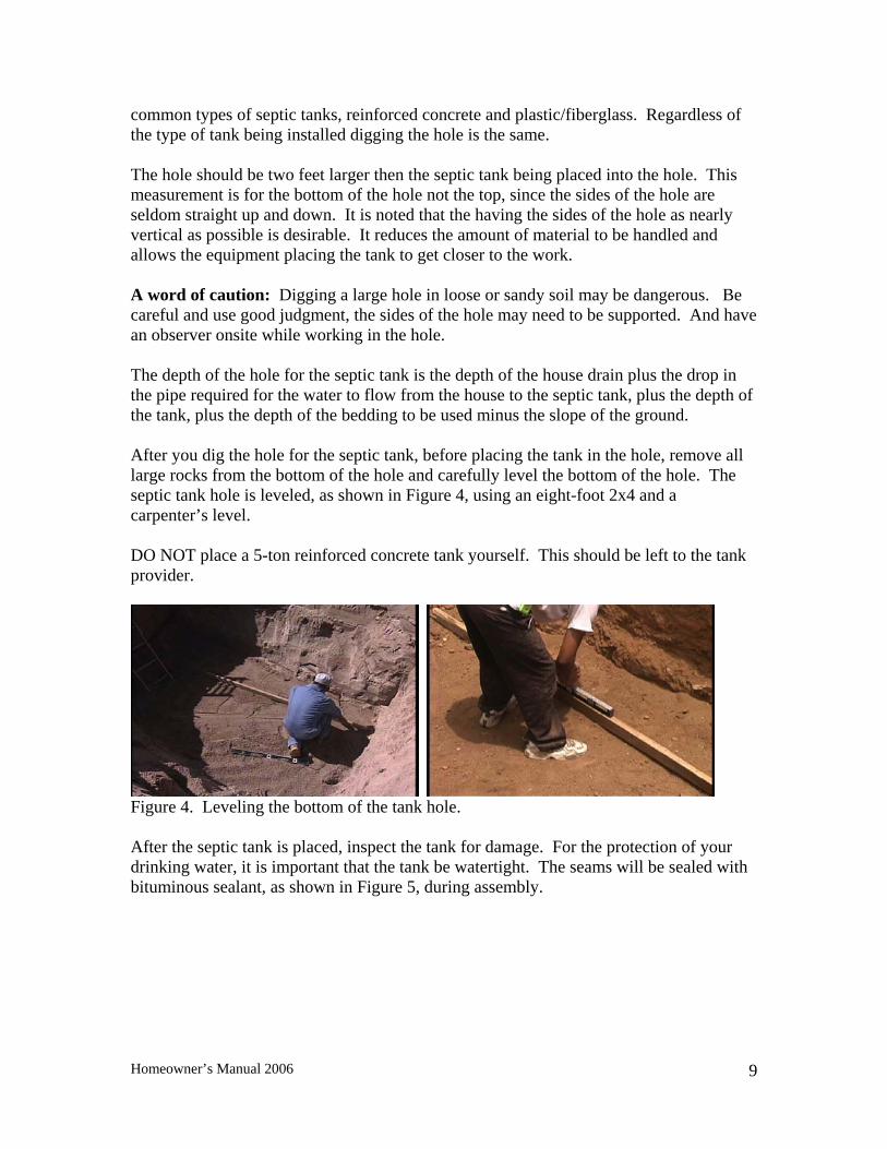
Figure 4. Leveling the bottom of the tank hole. After the septic tank is placed, inspect the tank for damage. For the protection of your drinking water, it is important that the tank be watertight. The seams will be sealed with bituminous sealant, as shown in Figure 5, during assembly.
Homeowner’s Manual 2006
9
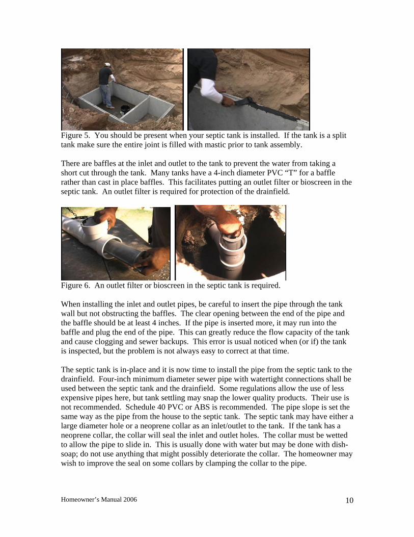
Figure 5. You should be present when your septic tank is installed. If the tank is a split tank make sure the entire joint is filled with mastic prior to tank assembly. There are baffles at the inlet and outlet to the tank to prevent the water from taking a short cut through the tank. Many tanks have a 4-inch diameter PVC “T” for a baffle rather than cast in place baffles. This facilitates putting an outlet filter or bioscreen in the septic tank. An outlet filter is required for protection of the drainfield.
Figure 6. An outlet filter or bioscreen in the septic tank is required. When installing the inlet and outlet pipes, be careful to insert the pipe through the tank wall but not obstructing the baffles. The clear opening between the end of the pipe and the baffle should be at least 4 inches. If the pipe is inserted more, it may run into the baffle and plug the end of the pipe. This can greatly reduce the flow capacity of the tank and cause clogging and sewer backups. This error is usual noticed when (or if) the tank is inspected, but the problem is not always easy to correct at that time. The septic tank is in-place and it is now time to install the pipe from the septic tank to the drainfield. Four-inch minimum diameter sewer pipe with watertight connections shall be used between the septic tank and the drainfield. Some regulations allow the use of less expensive pipes here, but tank settling may snap the lower quality products. Their use is not recommended. Schedule 40 PVC or ABS is recommended. The pipe slope is set the same way as the pipe from the house to the septic tank. The septic tank may have either a large diameter hole or a neoprene collar as an inlet/outlet to the tank. If the tank has a neoprene collar, the collar will seal the inlet and outlet holes. The collar must be wetted to allow the pipe to slide in. This is usually done with water but may be done with dish-soap; do not use anything that might possibly deteriorate the collar. The homeowner may wish to improve the seal on some collars by clamping the collar to the pipe.
Homeowner’s Manual 2006
10
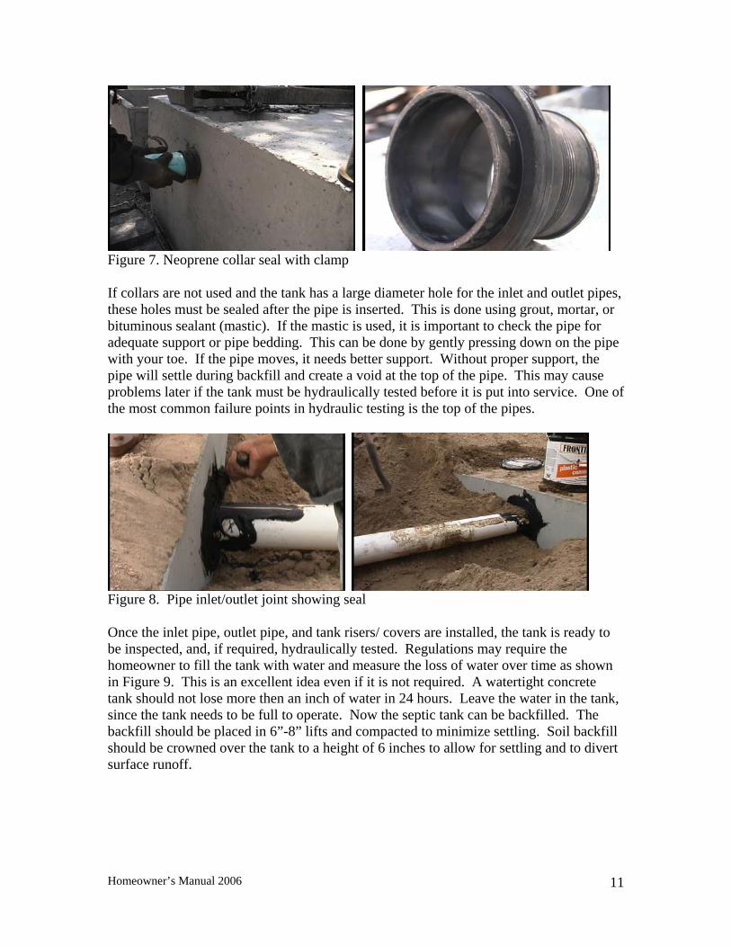
Figure 7. Neoprene collar seal with clamp If collars are not used and the tank has a large diameter hole for the inlet and outlet pipes, these holes must be sealed after the pipe is inserted. This is done using grout, mortar, or bituminous sealant (mastic). If the mastic is used, it is important to check the pipe for adequate support or pipe bedding. This can be done by gently pressing down on the pipe with your toe. If the pipe moves, it needs better support. Without proper support, the pipe will settle during backfill and create a void at the top of the pipe. This may cause problems later if the tank must be hydraulically tested before it is put into service. One of the most common failure points in hydraulic testing is the top of the pipes.
Figure 8. Pipe inlet/outlet joint showing seal Once the inlet pipe, outlet pipe, and tank risers/ covers are installed, the tank is ready to be inspected, and, if required, hydraulically tested. Regulations may require the homeowner to fill the tank with water and measure the loss of water over time as shown in Figure 9. This is an excellent idea even if it is not required. A watertight concrete tank should not lose more then an inch of water in 24 hours. Leave the water in the tank, since the tank needs to be full to operate. Now the septic tank can be backfilled. The backfill should be placed in 6”-8” lifts and compacted to minimize settling. Soil backfill should be crowned over the tank to a height of 6 inches to allow for settling and to divert surface runoff.
Homeowner’s Manual 2006
11
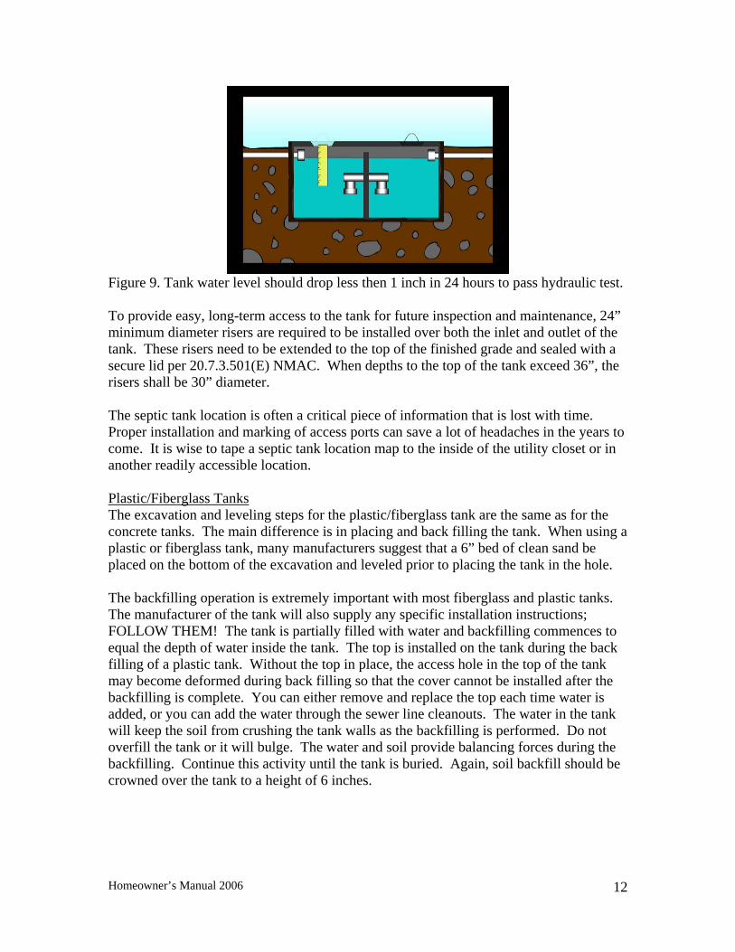
Figure 9. Tank water level should drop less then 1 inch in 24 hours to pass hydraulic test. To provide easy, long-term access to the tank for future inspection and maintenance, 24” minimum diameter risers are required to be installed over both the inlet and outlet of the tank. These risers need to be extended to the top of the finished grade and sealed with a secure lid per 20.7.3.501(E) NMAC. When depths to the top of the tank exceed 36”, the risers shall be 30” diameter. The septic tank location is often a critical piece of information that is lost with time. Proper installation and marking of access ports can save a lot of headaches in the years to come. It is wise to tape a septic tank location map to the inside of the utility closet or in another readily accessible location. Plastic/Fiberglass Tanks The excavation and leveling steps for the plastic/fiberglass tank are the same as for the concrete tanks. The main difference is in placing and back filling the tank. When using a plastic or fiberglass tank, many manufacturers suggest that a 6” bed of clean sand be placed on the bottom of the excavation and leveled prior to placing the tank in the hole. The backfilling operation is extremely important with most fiberglass and plastic tanks. The manufacturer of the tank will also supply any specific installation instructions; FOLLOW THEM! The tank is partially filled with water and backfilling commences to equal the depth of water inside the tank. The top is installed on the tank during the back filling of a plastic tank. Without the top in place, the access hole in the top of the tank may become deformed during back filling so that the cover cannot be installed after the backfilling is complete. You can either remove and replace the top each time water is added, or you can add the water through the sewer line cleanouts. The water in the tank will keep the soil from crushing the tank walls as the backfilling is performed. Do not overfill the tank or it will bulge. The water and soil provide balancing forces during the backfilling. Continue this activity until the tank is buried. Again, soil backfill should be crowned over the tank to a height of 6 inches.
Homeowner’s Manual 2006
12
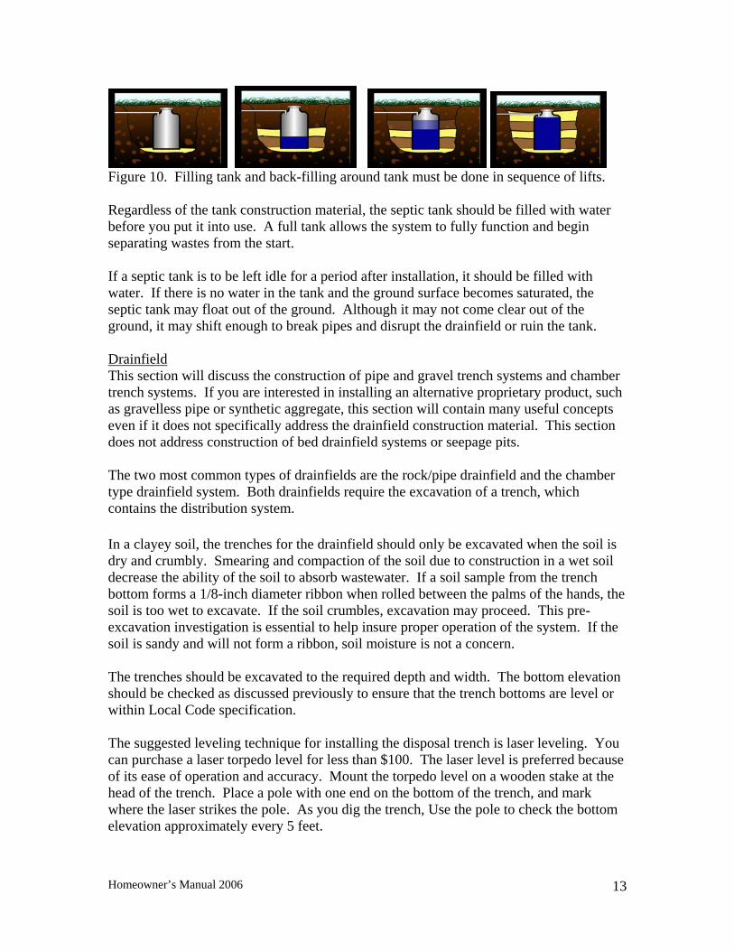
Figure 10. Filling tank and back-filling around tank must be done in sequence of lifts. Regardless of the tank construction material, the septic tank should be filled with water before you put it into use. A full tank allows the system to fully function and begin separating wastes from the start. If a septic tank is to be left idle for a period after installation, it should be filled with water. If there is no water in the tank and the ground surface becomes saturated, the septic tank may float out of the ground. Although it may not come clear out of the ground, it may shift enough to break pipes and disrupt the drainfield or ruin the tank. Drainfield This section will discuss the construction of pipe and gravel trench systems and chamber trench systems. If you are interested in installing an alternative proprietary product, such as gravelless pipe or synthetic aggregate, this section will contain many useful concepts even if it does not specifically address the drainfield construction material. This section does not address construction of bed drainfield systems or seepage pits. The two most common types of drainfields are the rock/pipe drainfield and the chamber type drainfield system. Both drainfields require the excavation of a trench, which contains the distribution system. In a clayey soil, the trenches for the drainfield should only be excavated when the soil is dry and crumbly. Smearing and compaction of the soil due to construction in a wet soil decrease the ability of the soil to absorb wastewater. If a soil sample from the trench bottom forms a 1/8-inch diameter ribbon when rolled between the palms of the hands, the soil is too wet to excavate. If the soil crumbles, excavation may proceed. This pre-excavation investigation is essential to help insure proper operation of the system. If the soil is sandy and will not form a ribbon, soil moisture is not a concern. The trenches should be excavated to the required depth and width. The bottom elevation should be checked as discussed previously to ensure that the trench bottoms are level or within Local Code specification. The suggested leveling technique for installing the disposal trench is laser leveling. You can purchase a laser torpedo level for less than $100. The laser level is preferred because of its ease of operation and accuracy. Mount the torpedo level on a wooden stake at the head of the trench. Place a pole with one end on the bottom of the trench, and mark where the laser strikes the pole. As you dig the trench, Use the pole to check the bottom elevation approximately every 5 feet.
Homeowner’s Manual 2006
13
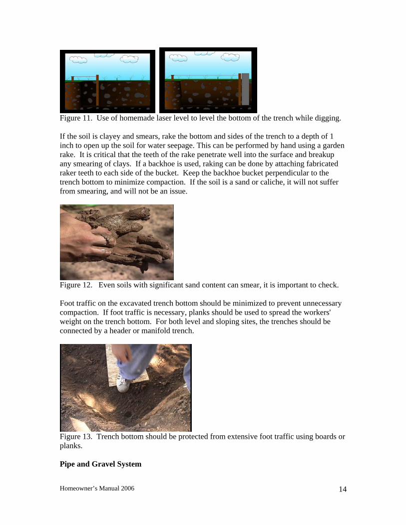
Figure 11. Use of homemade laser level to level the bottom of the trench while digging. If the soil is clayey and smears, rake the bottom and sides of the trench to a depth of 1 inch to open up the soil for water seepage. This can be performed by hand using a garden rake. It is critical that the teeth of the rake penetrate well into the surface and breakup any smearing of clays. If a backhoe is used, raking can be done by attaching fabricated raker teeth to each side of the bucket. Keep the backhoe bucket perpendicular to the trench bottom to minimize compaction. If the soil is a sand or caliche, it will not suffer from smearing, and will not be an issue.
Figure 12. Even soils with significant sand content can smear, it is important to check. Foot traffic on the excavated trench bottom should be minimized to prevent unnecessary compaction. If foot traffic is necessary, planks should be used to spread the workers' weight on the trench bottom. For both level and sloping sites, the trenches should be connected by a header or manifold trench.
Figure 13. Trench bottom should be protected from extensive foot traffic using boards or planks. Pipe and Gravel System
Homeowner’s Manual 2006
14
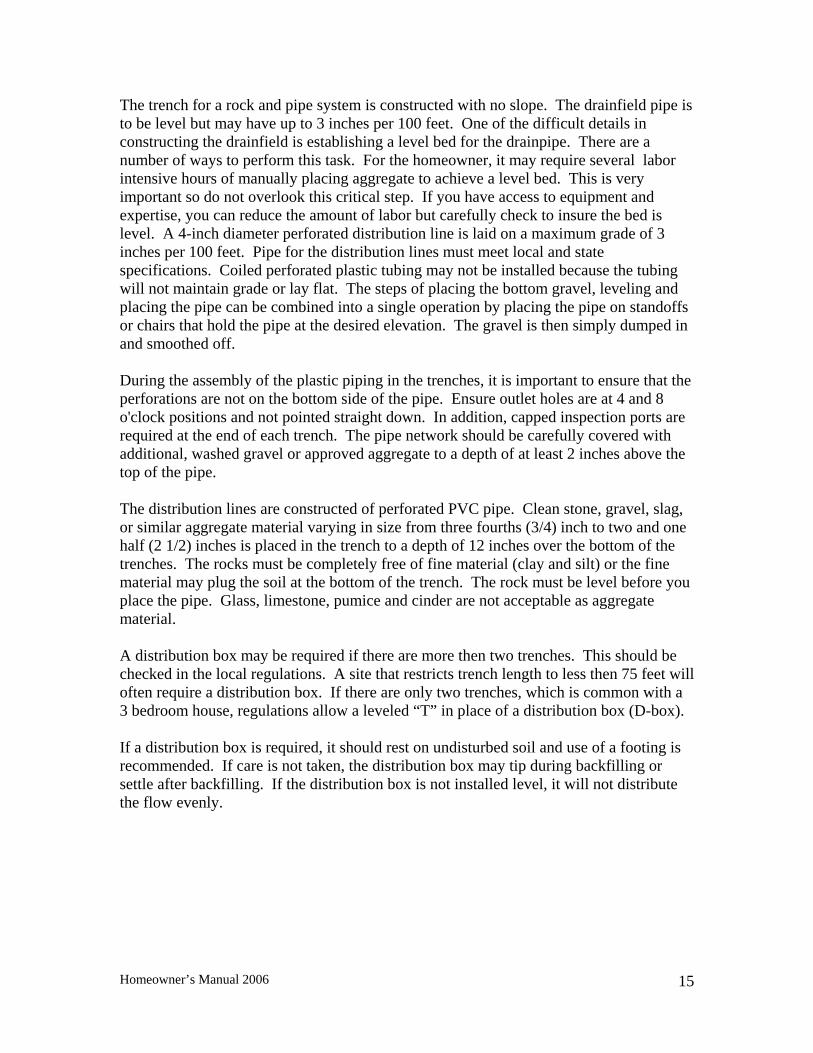
The trench for a rock and pipe system is constructed with no slope. The drainfield pipe is to be level but may have up to 3 inches per 100 feet. One of the difficult details in constructing the drainfield is establishing a level bed for the drainpipe. There are a number of ways to perform this task. For the homeowner, it may require several labor intensive hours of manually placing aggregate to achieve a level bed. This is very important so do not overlook this critical step. If you have access to equipment and expertise, you can reduce the amount of labor but carefully check to insure the bed is level. A 4-inch diameter perforated distribution line is laid on a maximum grade of 3 inches per 100 feet. Pipe for the distribution lines must meet local and state specifications. Coiled perforated plastic tubing may not be installed because the tubing will not maintain grade or lay flat. The steps of placing the bottom gravel, leveling and placing the pipe can be combined into a single operation by placing the pipe on standoffs or chairs that hold the pipe at the desired elevation. The gravel is then simply dumped in and smoothed off. During the assembly of the plastic piping in the trenches, it is important to ensure that the perforations are not on the bottom side of the pipe. Ensure outlet holes are at 4 and 8 o'clock positions and not pointed straight down. In addition, capped inspection ports are required at the end of each trench. The pipe network should be carefully covered with additional, washed gravel or approved aggregate to a depth of at least 2 inches above the top of the pipe. The distribution lines are constructed of perforated PVC pipe. Clean stone, gravel, slag, or similar aggregate material varying in size from three fourths (3/4) inch to two and one half (2 1/2) inches is placed in the trench to a depth of 12 inches over the bottom of the trenches. The rocks must be completely free of fine material (clay and silt) or the fine material may plug the soil at the bottom of the trench. The rock must be level before you place the pipe. Glass, limestone, pumice and cinder are not acceptable as aggregate material. A distribution box may be required if there are more then two trenches. This should be checked in the local regulations. A site that restricts trench length to less then 75 feet will often require a distribution box. If there are only two trenches, which is common with a 3 bedroom house, regulations allow a leveled “T” in place of a distribution box (D-box). If a distribution box is required, it should rest on undisturbed soil and use of a footing is recommended. If care is not taken, the distribution box may tip during backfilling or settle after backfilling. If the distribution box is not installed level, it will not distribute the flow evenly.
Homeowner’s Manual 2006
15
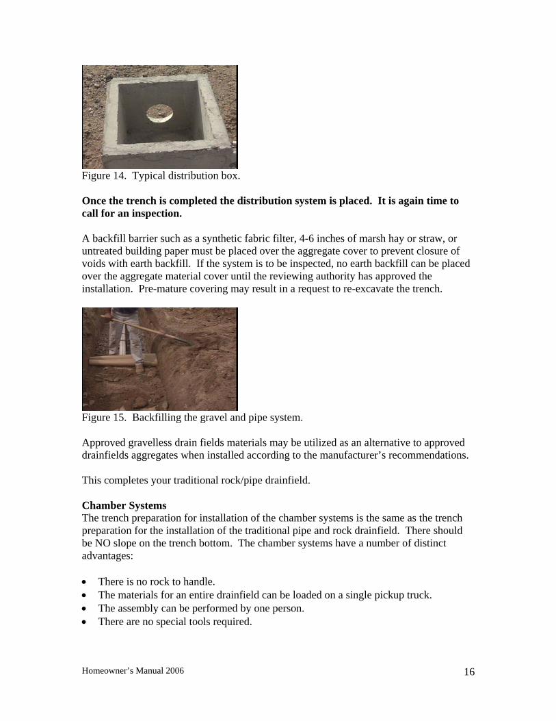
Figure 14. Typical distribution box. Once the trench is completed the distribution system is placed. It is again time to call for an inspection. A backfill barrier such as a synthetic fabric filter, 4-6 inches of marsh hay or straw, or untreated building paper must be placed over the aggregate cover to prevent closure of voids with earth backfill. If the system is to be inspected, no earth backfill can be placed over the aggregate material cover until the reviewing authority has approved the installation. Pre-mature covering may result in a request to re-excavate the trench.
Figure 15. Backfilling the gravel and pipe system. Approved gravelless drain fields materials may be utilized as an alternative to approved drainfields aggregates when installed according to the manufacturer’s recommendations. This completes your traditional rock/pipe drainfield. Chamber Systems The trench preparation for installation of the chamber systems is the same as the trench preparation for the installation of the traditional pipe and rock drainfield. There should be NO slope on the trench bottom. The chamber systems have a number of distinct advantages: • There is no rock to handle. • The materials for an entire drainfield can be loaded on a single pickup truck. • The assembly can be performed by one person. • There are no special tools required.
Homeowner’s Manual 2006
16
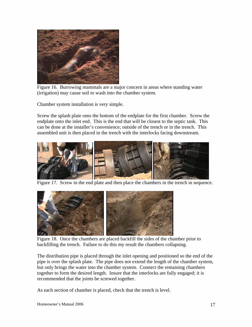
Figure 16. Burrowing mammals are a major concern in areas where standing water (irrigation) may cause soil to wash into the chamber system. Chamber system installation is very simple. Screw the splash plate onto the bottom of the endplate for the first chamber. Screw the endplate onto the inlet end. This is the end that will be closest to the septic tank. This can be done at the installer’s convenience; outside of the trench or in the trench. This assembled unit is then placed in the trench with the interlocks facing downstream.
Figure 17. Screw in the end plate and then place the chambers in the trench in sequence.
Figure 18. Once the chambers are placed backfill the sides of the chamber prior to backfilling the trench. Failure to do this my result the chambers collapsing. The distribution pipe is placed through the inlet opening and positioned so the end of the pipe is over the splash plate. The pipe does not extend the length of the chamber system, but only brings the water into the chamber system. Connect the remaining chambers together to form the desired length. Insure that the interlocks are fully engaged; it is recommended that the joints be screwed together. As each section of chamber is placed, check that the trench is level.
Homeowner’s Manual 2006
17
The closed endplate is screwed to the downstream end of the last chamber. If the system is to be either a looped system or a series system an open endplate will be installed instead of the closed endplate. It is critical with these systems that the trench be the right width, so the chamber is not under stress as it sits in the trench. It is also important that the sides of the chamber be filled prior to backfilling. This provides support for the arch so the chamber does not collapse or cut into the underlying soil during backfilling. Fill the sidewall area to the top of the slots with native soil and walk the soil into place. Now the chamber system is ready for the trench to be backfilled. The trenches should be backfilled with excavated soil and compact slightly. Individual trenches can be excavated and completed in sequence for ease of construction. Since settlement may take 6-12 months, the construction area should be sodded or seeded immediately, using grasses adapted to the area.
Homeowner’s Manual 2006
18

Appendix I: Application for a Liquid Waste Permit (Septic Tank Permit Application)
This section contains the form used in applying for your septic tank permit, and detailed instructions for filling out the form.
Homeowner’s Manual 2006
19

Appendix II: Contact Information for Assistance
This section includes addresses of those in NM who are available to answer questions regarding the construction.
Include New Mexico One Call 1800-321-ALERT
Homeowner’s Manual 2006
20