A Homebrew 40M Vertical with Elevated RadialsPage 1 of 9 April 2017 W1DYJ ~ 40M Vertical A Homebrew...
9
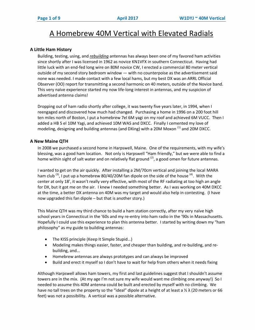
Page 1 of 9 April 2017 W1DYJ ~ 40M Vertical A Homebrew 40M Vertical with Elevated Radials A Little Ham History Building, testing, using, and rebuilding antennas has always been one of my favored ham activities since shortly after I was licensed in 1962 as novice KN1VFX in southern Connecticut. Having had little luck with an end-fed long wire on 80M novice CW, I erected a commercial 80 meter vertical outside of my second story bedroom window — with no counterpoise as the advertisement said none was needed. I made contact with a few local hams, but my best DX was an ARRL Official Observer (OO) report for transmitting a second harmonic on 40 meters, outside of the Novice band. This very naïve experience started my now life-long interest in antennas, and my suspicion of advertised antenna claims! Dropping out of ham radio shortly after college, it was twenty five years later, in 1994, when I reengaged and discovered how much had changed. Purchasing a home in 1996 on a 200 foot hill ten miles north of Boston, I put a homebrew 7el 6M yagi on my roof and achieved 6M VUCC. Then I added a HB 5 el 10M Yagi, and achieved 10M WAS and DXCC. Finally I cemented my love of modeling, designing and building antennas (and DXing) with a 20M Moxon (1) and 20M DXCC. A New Maine QTH In 2008 we purchased a second home in Harpswell, Maine. One of the requirements, with my wife’s blessing, was a good ham location. Not only is Harpswell “Ham friendly,” but we were able to find a home within sight of salt water and on relatively flat ground (2) , a good omen for future antennas. I wanted to get on the air quickly. After installing a 2M/70cm vertical and joining the local MARA ham club (3) , I put up a homebrew 80/40/20M fan dipole on the side of the house (4) . With the center at only 18’, it wasn’t really very effective, with most of the RF radiating at too high an angle for DX, but it got me on the air. I knew I needed something better. As I was working on 40M DXCC at the time, a better DX antenna on 40M was my target and would also help in contesting. (I have now upgraded this fan dipole – but that is another story.) This Maine QTH was my third chance to build a ham station correctly, after my very naïve high school years in Connecticut in the ‘60s and my re-entry into ham radio in the ‘90s in Massachusetts. Hopefully I could use this experience to plan this antenna better. I started by writing down my “ham philosophy” as my guide to building antennas: The KISS principle (Keep It Simple Stupid…) Modeling makes things easier, faster, and cheaper than building, and re-building, and re- building, and… Homebrew antennas are always prototypes and can always be improved Build and erect it myself so I don’t have to wait for help from others when it needs fixing Although Harpswell allows ham towers, my first and last guidelines suggest that I shouldn’t assume towers are in the mix. (At my age I’m not sure my wife would want me climbing one anyway!) So I needed to assume this 40M antenna could be built and erected by myself with no climbing. We have no tall trees on the property so the “ideal” dipole at a height of at least a ½ λ (20 meters or 66 feet) was not a possibility. A vertical was a possible alternative.
Transcript of A Homebrew 40M Vertical with Elevated RadialsPage 1 of 9 April 2017 W1DYJ ~ 40M Vertical A Homebrew...
Page 1 of 9 April 2017 W1DYJ ~ 40M Vertical
A Homebrew 40M Vertical with Elevated Radials
A Little Ham History
Building, testing, using, and rebuilding antennas has always been one of my favored ham activities since shortly after I was licensed in 1962 as novice KN1VFX in southern Connecticut. Having had little luck with an end-fed long wire on 80M novice CW, I erected a commercial 80 meter vertical outside of my second story bedroom window — with no counterpoise as the advertisement said none was needed. I made contact with a few local hams, but my best DX was an ARRL Official Observer (OO) report for transmitting a second harmonic on 40 meters, outside of the Novice band. This very naïve experience started my now life-long interest in antennas, and my suspicion of advertised antenna claims! Dropping out of ham radio shortly after college, it was twenty five years later, in 1994, when I reengaged and discovered how much had changed. Purchasing a home in 1996 on a 200 foot hill ten miles north of Boston, I put a homebrew 7el 6M yagi on my roof and achieved 6M VUCC. Then I added a HB 5 el 10M Yagi, and achieved 10M WAS and DXCC. Finally I cemented my love of modeling, designing and building antennas (and DXing) with a 20M Moxon (1) and 20M DXCC.
A New Maine QTH
In 2008 we purchased a second home in Harpswell, Maine. One of the requirements, with my wife’s blessing, was a good ham location. Not only is Harpswell “Ham friendly,” but we were able to find a home within sight of salt water and on relatively flat ground (2), a good omen for future antennas. I wanted to get on the air quickly. After installing a 2M/70cm vertical and joining the local MARA ham club (3), I put up a homebrew 80/40/20M fan dipole on the side of the house (4). With the center at only 18’, it wasn’t really very effective, with most of the RF radiating at too high an angle for DX, but it got me on the air. I knew I needed something better. As I was working on 40M DXCC at the time, a better DX antenna on 40M was my target and would also help in contesting. (I have now upgraded this fan dipole – but that is another story.)
This Maine QTH was my third chance to build a ham station correctly, after my very naïve high school years in Connecticut in the ‘60s and my re-entry into ham radio in the ‘90s in Massachusetts. Hopefully I could use this experience to plan this antenna better. I started by writing down my “ham philosophy” as my guide to building antennas:
The KISS principle (Keep It Simple Stupid…)
Modeling makes things easier, faster, and cheaper than building, and re-building, and re-building, and…
Homebrew antennas are always prototypes and can always be improved
Build and erect it myself so I don’t have to wait for help from others when it needs fixing Although Harpswell allows ham towers, my first and last guidelines suggest that I shouldn’t assume towers are in the mix. (At my age I’m not sure my wife would want me climbing one anyway!) So I needed to assume this 40M antenna could be built and erected by myself with no climbing. We have no tall trees on the property so the “ideal” dipole at a height of at least a ½ λ (20 meters or 66 feet) was not a possibility. A vertical was a possible alternative.
Page 2 of 9 April 2017 W1DYJ ~ 40M Vertical
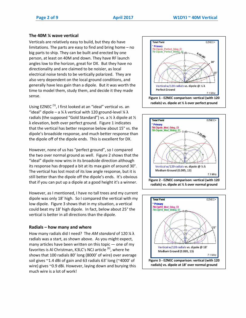
Figure 1 - EZNEC comparison: vertical (with 120
radials) vs. dipole at ½ λ over perfect ground
The 40M ¼ wave vertical
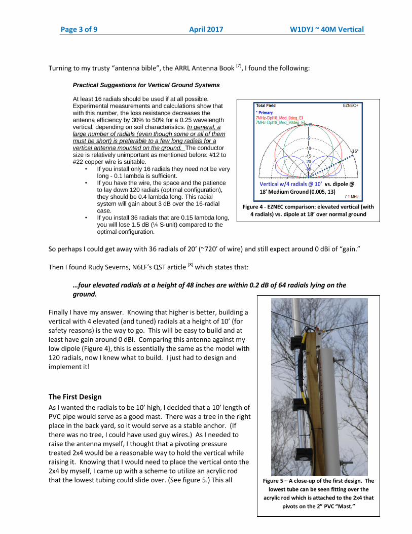
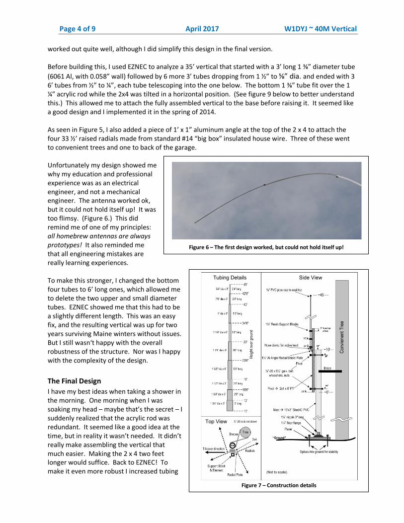
Verticals are relatively easy to build, but they do have limitations. The parts are easy to find and bring home – no big parts to ship. They can be built and erected by one person, at least on 40M and down. They have RF launch angles low to the horizon, great for DX. But they have no directionality and are claimed to be noisier, as local electrical noise tends to be vertically polarized. They are also very dependent on the local ground conditions, and generally have less gain than a dipole. But it was worth the time to model them, study them, and decide it they made sense. Using EZNEC (5), I first looked at an “ideal” vertical vs. an “ideal” dipole – a ¼ λ vertical with 120 ground-level ¼ λ radials (the supposed “Gold Standard”) vs. a ½ λ dipole at ½ λ elevation, both over perfect ground. Figure 1 indicates that the vertical has better response below about 15° vs. the dipole’s broadside response, and much better response than the dipole off of the dipole ends. This is excellent for DX. However, none of us has “perfect ground”, so I compared the two over normal ground as well. Figure 2 shows that the “ideal” dipole now wins in its broadside direction although its response has dropped a bit at its max gain of around 30°. The vertical has lost most of its low angle response, but it is still better than the dipole off the dipole’s ends. It’s obvious that if you can put up a dipole at a good height it’s a winner. However, as I mentioned, I have no tall trees and my current dipole was only 18’ high. So I compared the vertical with my low dipole. Figure 3 shows that in my situation, a vertical could beat my 18’ high dipole. In fact, below about 25° the vertical is better in all directions than the dipole.
Radials – how many and where
How many radials did I need? The AM standard of 120 ¼ λ radials was a start, as shown above. As you might expect, many articles have been written on this topic — one of my favorites is Al Christman, K3LC’s NCJ article [6], where he shows that 100 radials 80’ long (8000’ of wire) over average soil gives ~1.4 dBi of gain and 63 radials 63’ long (~4000’ of wire) gives ~0.9 dBi. However, laying down and burying this much wire is a lot of work!
Figure 2 - EZNEC comparison: vertical (with 120
radials) vs. dipole at ½ λ over normal ground
Figure 3 - EZNEC comparison: vertical (with 120
radials) vs. dipole at 18’ over normal ground
Page 3 of 9 April 2017 W1DYJ ~ 40M Vertical
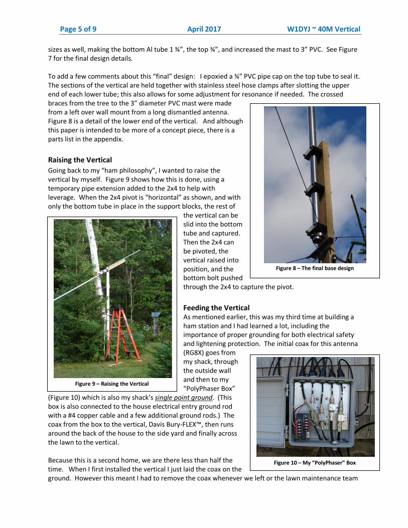
Figure 4 - EZNEC comparison: elevated vertical (with
4 radials) vs. dipole at 18’ over normal ground
Turning to my trusty “antenna bible”, the ARRL Antenna Book [7], I found the following:
Practical Suggestions for Vertical Ground Systems At least 16 radials should be used if at all possible. Experimental measurements and calculations show that with this number, the loss resistance decreases the antenna efficiency by 30% to 50% for a 0.25 wavelength vertical, depending on soil characteristics. In general, a large number of radials (even though some or all of them must be short) is preferable to a few long radials for a vertical antenna mounted on the ground. The conductor size is relatively unimportant as mentioned before: #12 to #22 copper wire is suitable.
• If you install only 16 radials they need not be very long - 0.1 lambda is sufficient.
• If you have the wire, the space and the patience to lay down 120 radials (optimal configuration), they should be 0.4 lambda long. This radial system will gain about 3 dB over the 16-radial case.
• If you install 36 radials that are 0.15 lambda long, you will lose 1.5 dB (¼ S-unit) compared to the optimal configuration.
So perhaps I could get away with 36 radials of 20’ (~720’ of wire) and still expect around 0 dBi of “gain.” Then I found Rudy Severns, N6LF’s QST article [8] which states that:
…four elevated radials at a height of 48 inches are within 0.2 dB of 64 radials lying on the ground.
Finally I have my answer. Knowing that higher is better, building a vertical with 4 elevated (and tuned) radials at a height of 10’ (for safety reasons) is the way to go. This will be easy to build and at least have gain around 0 dBi. Comparing this antenna against my low dipole (Figure 4), this is essentially the same as the model with 120 radials, now I knew what to build. I just had to design and implement it!
The First Design
As I wanted the radials to be 10’ high, I decided that a 10’ length of PVC pipe would serve as a good mast. There was a tree in the right place in the back yard, so it would serve as a stable anchor. (If there was no tree, I could have used guy wires.) As I needed to raise the antenna myself, I thought that a pivoting pressure treated 2x4 would be a reasonable way to hold the vertical while raising it. Knowing that I would need to place the vertical onto the 2x4 by myself, I came up with a scheme to utilize an acrylic rod that the lowest tubing could slide over. (See figure 5.) This all
Figure 5 – A close-up of the first design. The
lowest tube can be seen fitting over the
acrylic rod which is attached to the 2x4 that
pivots on the 2” PVC “Mast.”
Page 4 of 9 April 2017 W1DYJ ~ 40M Vertical
Figure 7 – Construction details
worked out quite well, although I did simplify this design in the final version. Before building this, I used EZNEC to analyze a 35’ vertical that started with a 3’ long 1 ⅜” diameter tube
(6061 Al, with 0.058” wall) followed by 6 more 3’ tubes dropping from 1 ½” to ⅝” dia. and ended with 3 6’ tubes from ½” to ¼”, each tube telescoping into the one below. The bottom 1 ⅜” tube fit over the 1 ¼” acrylic rod while the 2x4 was tilted in a horizontal position. (See figure 9 below to better understand this.) This allowed me to attach the fully assembled vertical to the base before raising it. It seemed like a good design and I implemented it in the spring of 2014. As seen in Figure 5, I also added a piece of 1’ x 1” aluminum angle at the top of the 2 x 4 to attach the four 33 ½’ raised radials made from standard #14 “big box” insulated house wire. Three of these went to convenient trees and one to back of the garage. Unfortunately my design showed me why my education and professional experience was as an electrical engineer, and not a mechanical engineer. The antenna worked ok, but it could not hold itself up! It was too flimsy. (Figure 6.) This did remind me of one of my principles: all homebrew antennas are always prototypes! It also reminded me that all engineering mistakes are really learning experiences. To make this stronger, I changed the bottom four tubes to 6’ long ones, which allowed me to delete the two upper and small diameter tubes. EZNEC showed me that this had to be a slightly different length. This was an easy fix, and the resulting vertical was up for two years surviving Maine winters without issues. But I still wasn‘t happy with the overall robustness of the structure. Nor was I happy with the complexity of the design.
The Final Design
I have my best ideas when taking a shower in the morning. One morning when I was soaking my head – maybe that’s the secret – I suddenly realized that the acrylic rod was redundant. It seemed like a good idea at the time, but in reality it wasn’t needed. It didn’t really make assembling the vertical that much easier. Making the 2 x 4 two feet longer would suffice. Back to EZNEC! To make it even more robust I increased tubing
Figure 6 – The first design worked, but could not hold itself up!
Page 5 of 9 April 2017 W1DYJ ~ 40M Vertical
sizes as well, making the bottom Al tube 1 ¾”, the top ¾”, and increased the mast to 3” PVC. See Figure 7 for the final design details. To add a few comments about this “final” design: I epoxied a ¾” PVC pipe cap on the top tube to seal it. The sections of the vertical are held together with stainless steel hose clamps after slotting the upper end of each lower tube; this also allows for some adjustment for resonance if needed. The crossed braces from the tree to the 3” diameter PVC mast were made from a left over wall mount from a long dismantled antenna. Figure 8 is a detail of the lower end of the vertical. And although this paper is intended to be more of a concept piece, there is a parts list in the appendix.
Raising the Vertical
Going back to my “ham philosophy”, I wanted to raise the vertical by myself. Figure 9 shows how this is done, using a temporary pipe extension added to the 2x4 to help with leverage. When the 2x4 pivot is “horizontal” as shown, and with only the bottom tube in place in the support blocks, the rest of
the vertical can be slid into the bottom tube and captured. Then the 2x4 can be pivoted, the vertical raised into position, and the bottom bolt pushed through the 2x4 to capture the pivot.
Feeding the Vertical As mentioned earlier, this was my third time at building a ham station and I had learned a lot, including the importance of proper grounding for both electrical safety and lightening protection. The initial coax for this antenna (RG8X) goes from my shack, through the outside wall and then to my “PolyPhaser Box”
(Figure 10) which is also my shack’s single point ground. (This box is also connected to the house electrical entry ground rod with a #4 copper cable and a few additional ground rods.) The coax from the box to the vertical, Davis Bury-FLEX™, then runs around the back of the house to the side yard and finally across the lawn to the vertical. Because this is a second home, we are there less than half the time. When I first installed the vertical I just laid the coax on the ground. However this meant I had to remove the coax whenever we left or the lawn maintenance team
Figure 8 – The final base design
Figure 9 – Raising the Vertical
Figure 10 – My “PolyPhaser” Box
Page 6 of 9 April 2017 W1DYJ ~ 40M Vertical
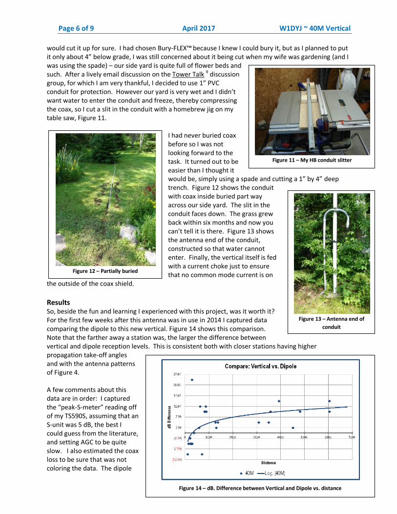
would cut it up for sure. I had chosen Bury-FLEX™ because I knew I could bury it, but as I planned to put it only about 4” below grade, I was still concerned about it being cut when my wife was gardening (and I was using the spade) – our side yard is quite full of flower beds and such. After a lively email discussion on the Tower Talk 9 discussion group, for which I am very thankful, I decided to use 1” PVC conduit for protection. However our yard is very wet and I didn’t want water to enter the conduit and freeze, thereby compressing the coax, so I cut a slit in the conduit with a homebrew jig on my table saw, Figure 11.
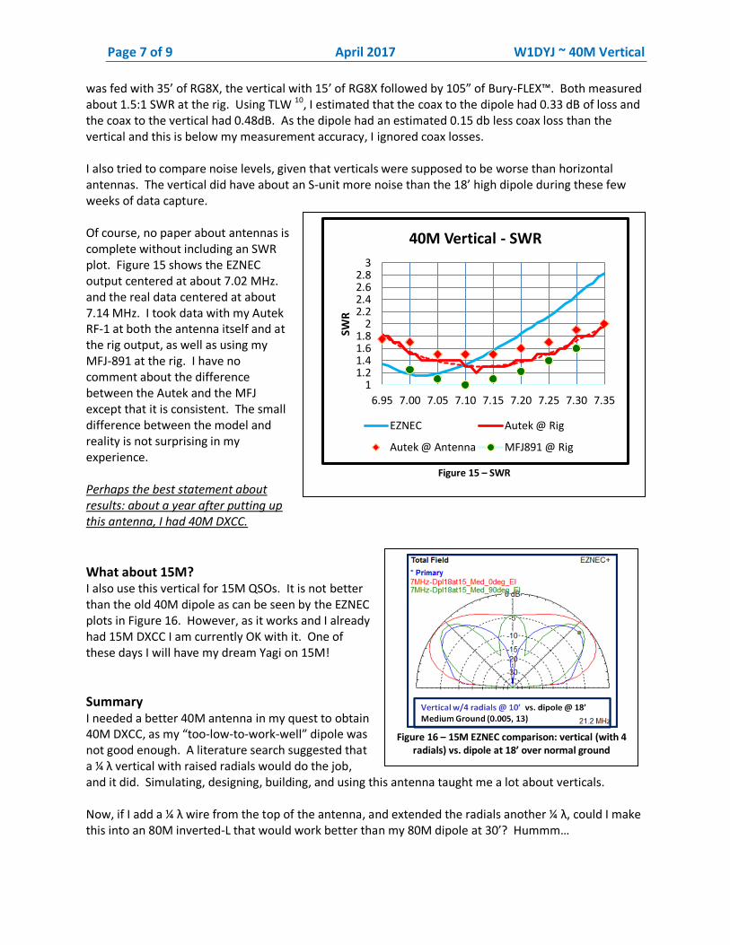
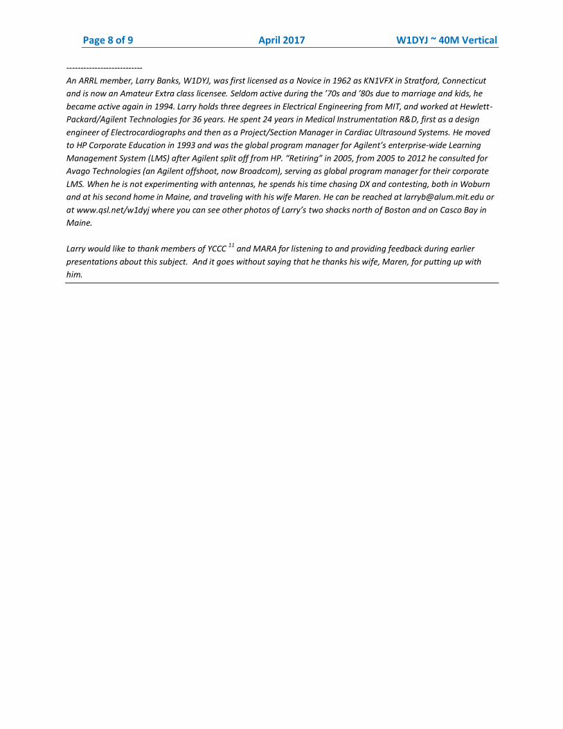
I had never buried coax before so I was not looking forward to the task. It turned out to be easier than I thought it would be, simply using a spade and cutting a 1” by 4” deep trench. Figure 12 shows the conduit with coax inside buried part way across our side yard. The slit in the conduit faces down. The grass grew back within six months and now you can’t tell it is there. Figure 13 shows the antenna end of the conduit, constructed so that water cannot enter. Finally, the vertical itself is fed with a current choke just to ensure that no common mode current is on
the outside of the coax shield.
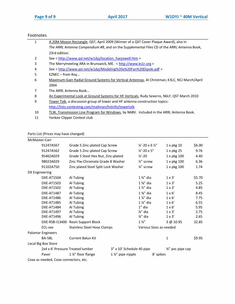
Results So, beside the fun and learning I experienced with this project, was it worth it? For the first few weeks after this antenna was in use in 2014 I captured data comparing the dipole to this new vertical. Figure 14 shows this comparison. Note that the farther away a station was, the larger the difference between vertical and dipole reception levels. This is consistent both with closer stations having higher propagation take-off angles and with the antenna patterns of Figure 4. A few comments about this data are in order: I captured the “peak-S-meter” reading off of my TS590S, assuming that an S-unit was 5 dB, the best I could guess from the literature, and setting AGC to be quite slow. I also estimated the coax loss to be sure that was not coloring the data. The dipole
Figure 11 – My HB conduit slitter
Figure 12 – Partially buried
Figure 13 – Antenna end of
conduit
Figure 14 – dB. Difference between Vertical and Dipole vs. distance
Page 7 of 9 April 2017 W1DYJ ~ 40M Vertical
Figure 16 – 15M EZNEC comparison: vertical (with 4
radials) vs. dipole at 18’ over normal ground
was fed with 35’ of RG8X, the vertical with 15’ of RG8X followed by 105” of Bury-FLEX™. Both measured about 1.5:1 SWR at the rig. Using TLW 10, I estimated that the coax to the dipole had 0.33 dB of loss and the coax to the vertical had 0.48dB. As the dipole had an estimated 0.15 db less coax loss than the vertical and this is below my measurement accuracy, I ignored coax losses. I also tried to compare noise levels, given that verticals were supposed to be worse than horizontal antennas. The vertical did have about an S-unit more noise than the 18’ high dipole during these few weeks of data capture. Of course, no paper about antennas is complete without including an SWR plot. Figure 15 shows the EZNEC output centered at about 7.02 MHz. and the real data centered at about 7.14 MHz. I took data with my Autek RF-1 at both the antenna itself and at the rig output, as well as using my MFJ-891 at the rig. I have no comment about the difference between the Autek and the MFJ except that it is consistent. The small difference between the model and reality is not surprising in my experience.
Perhaps the best statement about results: about a year after putting up this antenna, I had 40M DXCC.
What about 15M? I also use this vertical for 15M QSOs. It is not better than the old 40M dipole as can be seen by the EZNEC plots in Figure 16. However, as it works and I already had 15M DXCC I am currently OK with it. One of these days I will have my dream Yagi on 15M!
Summary I needed a better 40M antenna in my quest to obtain 40M DXCC, as my “too-low-to-work-well” dipole was not good enough. A literature search suggested that a ¼ λ vertical with raised radials would do the job, and it did. Simulating, designing, building, and using this antenna taught me a lot about verticals. Now, if I add a ¼ λ wire from the top of the antenna, and extended the radials another ¼ λ, could I make this into an 80M inverted-L that would work better than my 80M dipole at 30’? Hummm…
Figure 15 – SWR
1 1.2 1.4 1.6 1.8
2 2.2 2.4 2.6 2.8
3
6.95 7.00 7.05 7.10 7.15 7.20 7.25 7.30 7.35
SWR
40M Vertical - SWR
EZNEC Autek @ Rig
Autek @ Antenna MFJ891 @ Rig
Page 8 of 9 April 2017 W1DYJ ~ 40M Vertical
---------------------------
An ARRL member, Larry Banks, W1DYJ, was first licensed as a Novice in 1962 as KN1VFX in Stratford, Connecticut
and is now an Amateur Extra class licensee. Seldom active during the ’70s and ’80s due to marriage and kids, he
became active again in 1994. Larry holds three degrees in Electrical Engineering from MIT, and worked at Hewlett-
Packard/Agilent Technologies for 36 years. He spent 24 years in Medical Instrumentation R&D, first as a design
engineer of Electrocardiographs and then as a Project/Section Manager in Cardiac Ultrasound Systems. He moved
to HP Corporate Education in 1993 and was the global program manager for Agilent’s enterprise-wide Learning
Management System (LMS) after Agilent split off from HP. “Retiring” in 2005, from 2005 to 2012 he consulted for
Avago Technologies (an Agilent offshoot, now Broadcom), serving as global program manager for their corporate
LMS. When he is not experimenting with antennas, he spends his time chasing DX and contesting, both in Woburn
and at his second home in Maine, and traveling with his wife Maren. He can be reached at [email protected] or
at www.qsl.net/w1dyj where you can see other photos of Larry’s two shacks north of Boston and on Casco Bay in
Maine.
Larry would like to thank members of YCCC 11
and MARA for listening to and providing feedback during earlier
presentations about this subject. And it goes without saying that he thanks his wife, Maren, for putting up with
him.
Page 9 of 9 April 2017 W1DYJ ~ 40M Vertical
Footnotes
1 A 20M Moxon Rectangle, QST, April 2009 [Winner of a QST Cover Plaque Award], also in
The ARRL Antenna Compendium #8, and on the Supplemental Files CD of the ARRL Antenna Book,
23rd edition.
2 See < http://www.qsl.net/w1dyj/location_harpswell.htm >
3 The Merrymeeting ARA in Brunswick, ME. < http://www.ks1r.org >
4 See < http://www.qsl.net/w1dyj/Modeling%20a%20Fan%20Dipole.pdf >
5 EZNEC – from Roy…
6 Maximum-Gain Radial Ground Systems for Vertical Antennas, Al Christman, K3LC, NCJ March/April
2004
7 The ARRL Antenna Book…
8 An Experimental Look at Ground Systems for HF Verticals, Rudy Severns, N6LF, QST March 2010
9 Tower Talk, a discussion group of tower and HF antenna construction topics:
http://lists.contesting.com/mailman/listinfo/towertalk
10 TLW, Transmission Line Program for Windows, by N6BV. Included in the ARRL Antenna Book.
11 Yankee Clipper Contest club
Parts List (Prices may have changed)
McMaster-Carr
91247A567 Grade 5 Zinc-plated Cap Screw ¼’-20 x 6 ½” 1 x pkg 10 $6.00
91247A562 Grade 5 Zinc-plated Cap Screw ¼’-20 x 5” 1 x pkg 25 9.76
95462A029 Grade 5 Steel Hex Nut, Zinc-plated ¼’-20 1 x pkg 100 4.40
98023A029 Zinc Ylw-Chromate Grade 8 Washer ¼” screw 1 x pkg 100 6.36
91102A750 Zinc plated Steel Split Lock Washer ¼” screw 1 x pkg 100 1.74
DX Engineering
DXE-AT1504 Al Tubing 1 ¾” dia 1 x 3’ $5.70
DXE-AT1503 Al Tubing 1 ⅝” dia 1 x 3’ 5.25 DXE-AT1502 Al Tubing 1 ½” dia 1 x 3’ 4.85
DXE-AT1487 Al Tubing 1 ⅜” dia 1 x 6’ 8.45 DXE-AT1486 Al Tubing 1 ¼” dia 1 x 6’ 7.75 DXE-AT1485 Al Tubing 1 ⅛” dia 1 x 6’ 6.55 DXE-AT1484 Al Tubing 1” dia 1 x 6’ 5.95 DXE-AT1497 Al Tubing ⅞” dia 1 x 3’ 2.75 DXE-AT1496 Al Tubing ¾” dia 1 x 3’ 2.65
DXE-RSB-I13400 Resin Support Block 1 ¾” 3 @ 10.95 32.85
ECL-xxx Stainless Steel Hose Clamps Various Sizes as needed
Palomar Engineers
BA-58L Current Balun Kit 1 $9.95
Local Big Box Store
2x4 x 6’ Pressure Treated lumber 3” x 10’ Schedule 40 pipe ¾” pvc pipe cap
Paver 1 ¼” floor flange 1 ¼” pipe nipple 8’ spikes
Coax as needed, Coax connectors, etc.