A High-Pressure Premixed Flat-Flame Burner for … High-Pressure Premixed Flat-Flame Burner for ......
32
NASA Technical Paper 1318 A High-Pressure Premixed Flat-Flame Burner for Chemical Process Studies Irvin M. Miller } DECEMBER 1978 NASA https://ntrs.nasa.gov/search.jsp?R=19790006006 2018-07-08T21:32:42+00:00Z
Transcript of A High-Pressure Premixed Flat-Flame Burner for … High-Pressure Premixed Flat-Flame Burner for ......
NASA Technical Paper 1318
A High-Pressure PremixedFlat-Flame Burner forChemical Process Studies
Irvin M. Miller }
DECEMBER 1978
NASA
https://ntrs.nasa.gov/search.jsp?R=19790006006 2018-07-08T21:32:42+00:00Z
NASA Technical Paper 1318
A High-Pressure PremixedFlat-Flame Burner forChemical Process Studies
Irvin M. MillerLangley Research CenterHampton, Virginia
NASANational Aeronauticsand Space Administration
Scientific and TechnicalInformation Office
1978
SUMMARY
A premixed flat-flame burner was designed and tested for the purpose ofstudying chemical processes at high pressure, with the specific goal of study-ing pollutant formation in hydrocarbon flames. Successful operation of theburner was obtained with methane-air mixtures at equivalence ratios of 0.7, 0.9,and 1.1 and at pressures of 1.1, 5, 10, and 20 atm.
At each of the 12 pressure—equivalence-ratio combinations, the range offlame stability was determined as a function of reactant velocity. This veloc-ity is defined in the present study as the average velocity of the reactant gasmixture in the burner mixing chamber. For each of the three equivalence ratios,the upper stability limit generally decreased with increasing pressure. Asexpected for an equivalence ratio of 0.9, the lower stability limit correspondsclosely to the lower ignition limit for the same equivalence ratio.
To determine the maximum size of the thermocouple probe required for goodspatial resolution in flames, flame zone thicknesses and flame heights weremeasured from color photographs. Flame height is the distance between the topof the burner and the bottom of the flame zone. Flame heights ranged from 0.16to 0.85 mm, and flame zone thicknesses varied from 0.3 to 1.2 mm. These resultsshow that thermocouple probes should be about 0.03 mm or smaller for good spa-tial resolution of the flame.
INTRODUCTION
The premixed flat-flame burner has been used for many years by many inves-tigators to study flames in order to obtain a better understanding of combustionprocesses. The burner consists of either a bundle of small parallel channels ora fine porous metal disk contained at the end of a cylindrical chamber. A reac-tant gas mixture of fuel and oxidant flows upward through the fine passages atthe top of the burner, represented by the porous disk in figure 1, and emergesin a uniform velocity distribution across the upper surface of the burner.Ignition of the gas mixture produces a flat flame across and close to theburner. The burner is usually cooled at the circumference, and is designed tooperate over a wide range of stream velocities.
In the study of combustion processes, the premixed flame is often preferredover a diffusion flame (one in which the oxidant and fuel interdiffuse and burnat an interface). A premixed flame has a considerably simpler structure, andthe rate of combustion is governed by chemical rate processes. In a diffusionflame, the rate of combustion is governed by both chemical rate and diffusionprocesses. Hence, many chemical kinetic studies have been made with premixedflames and especially with premixed flat flames. The flat flame is also pre-ferred because flame properties, such as temperature and composition, are uni-form in each plane parallel to the burner surface. Because of this uniformtemperature property, flame temperature measurements made by thermocouple

Flat flame
Porous disk
Oxidant
Mixing chamber
Fuel
Figure 1.- Premixed flat-flame burner.
probes in these flames often do not require corrections for conduction errors,since the probes can usually be oriented in an isothermal plane of the flame.Since the properties of a premixed flat flame vary in one direction only, thisflame is also called a one-dimensional flame.
There are at.; least two particular disadvantages to the study of premixedflames at high pressure. One is the danger of flashback, which is the upstreampropagation of the flame through the burner to the gas mixture. This phenomenonusually occurs when the stream velocity instantly becomes smaller than the flamevelocity, as when the reactant flow is suddenly interrupted or stopped. Underinitial high-pressure conditions, the danger of flashback can cause a very high-pressure deflagration in the burner mixing chamber. There is also the danger ofa detonation resulting therefrom, as reported by Edse in reference 1. Becauseof these hazards, only a limited number of high-pressure studies using a pre-mixed flame have been made. These studies include soot formation and burningvelocity by Diederichsen and Wolfhard (refs. 2 and 3), soot formation byMacfarlane, Holderness, and Whitcher (ref. 4), and burning velocity by Edse(ref. 1) and Strauss and Edse (ref. 5). A recent study was made by Heberling(ref. 6) of flat flames at pressures from 1 to 18 atm involving measurements ofnitric oxide concentrations and flame temperatures. The second disadvantage isthat the reaction zone in the flame decreases in thickness with increasingpressure. This makes it increasingly difficult to probe and sample this zonewith good resolution.
In spite of these difficulties, the study of high-pressure premixed flatflames is needed to obtain a better understanding of combustion processes athigh pressure. For instance, such studies might be concerned with determiningthe governing chemical mechanisms that control the rate of formation of pollu-tants, such as nitrogen oxides, sulfur dioxide, and soot. Data on such premixedflames can be useful in helping to formulate combustion models for'predictingthe formation rate of pollutants in practical combustion systems. To implementsuch a study, a burner described in this report was designed to extend the work

initiated by Miller and Maahs (ref. 7), which involved pollutant formation inhigh-pressure diffusion flames.
The purpose of the present study is to design, test, and determine thestable operating range of a premixed flat-flame burner at high pressures as wellas the flame dimensions on such a burner, i.e., flame height (preheat zone) andflame thickness (reaction zone). The extent of the stability range and flamedimensions will determine the suitability of the burner for the study of chemi-cal processes in flames at high pressure. For this purpose, fuel-lean andnear-stoichiometric mixtures of methane and air were burned at pressures from1.1 to 20 atm.
SYMBOLS
AJ.J projected cross-sectional area of porous disk in burner, 1.27 cm
C constant, (mole-sec2)/(g-cm^-K)
F( ) mathematical function of ( )
f friction factor
K constant, moles/cm^
L depth of a porous medium, cm
M molecular weight, g/mole
ND Reynolds numberx\e
n number of moles
p pressure, atm (1 atm = 101.3 kPa)
p, absolute pressure in burner mixing chamber, atm
p average pressure in a porous medium, atm
Ap pressure drop across porous disk in burner, atm
q quenching diameter, mm
^£ quenching length, mm
R universal gas constant, (cm3-atm)/(mole-K)
S cross-sectional area of a porous medium, cm2
S surface area of a particle, cm2

T absolute temperature, K
TV absolute temperature in burner mixing chamber, K
T average absolute temperature in a porous medium, K
uj-, reactant velocity, cm/sec
u average velocity of fluid, cm/sec
V volume, cm^
• oV volumetric flow rate, cm°/sec
* -3Vj-j volumetric flow rate in burner mixing chamber, cmj/sec
v volume of"particle, cm
a pressure exponent, an empirical constant
3 temperature exponent, an empirical constant
e void fraction or porosity
y average viscosity of a fluid in a porous medium, g/(sec-cm)
p density of fluid, g/cm
cj> equivalence ratio
Subscripts:
a air
f fuel
ref reference value
s standard conditions of temperature and pressure, 293 K and 1 atm
1 upstream of porous medium
2 downstream of porous medium
DESIGN CONCEPT AND BURNER CONFIGURATION
The stabilization of a flame in a flat-flame burner is based on the factthat flame velocity, i.e., the velocity at which a flame propagates in a reac-tant gas mixture, varies with flame temperature (ref. 8). Thus, as the flamepropagates upstream to the burner surface, it loses an increasing amount ofheat to the burner, causing the flame temperature to drop until the flame

velocity is equal to the stream velocity of the unburned mixture upstream ofthe flame. Then the flat flame remains at a fixed distance close to the burnersurface. By increasing the stream velocity, the velocity of the flame and itstemperature must increase, which results in the flame taking a position fartheraway from the burner. By continually increasing the stream velocity, the flamecan approach the adiabatic flame temperature and hence the adiabatic flamevelocity. To more efficiently extract heat from the flame in order to obtain amore stable flame, the porous disk in the burner is usually radially cooled.The simplest means of cooling is a heat sink as shown in figure 2. Because ofits simplicity, this method of heat removal was chosen for the present burner.
Quartz shield
Bronze sleeve
Bronzeshield plate
Porous bronze disk
Nitrogen shield ring
ironze bushing
Mixing chamber
~Methane nozzle
Methane inlet
One of two thermo-couple probes (othernot shovn)
ironze body
Figure 2.- High-pressure flat-flame burner. Full scale.
As previously noted, the hazards of using a premixed burner operating atinitial high-pressure conditions are flashback, which can cause a very high-pressure deflagration in the mixing chamber, and possible detonation, where thepeak pressure is twice that of a deflagration for the same initial conditions(ref. 9). Flashback can be minimized by keeping the dimension of the narrowchannels in the burner plate below the quenching length q«. This length isdefined as the smallest separation between two parallel plates which will allowa flame to pass.
A study of the literature revealed that quenching length depends on pres-sure, temperature, geometry of quenching surface (such as a tube or slit), andreactant composition (ref. 10). Friedman and Johnston (refs. 11 and 12) studiedquenching length with a slit burner at various pressures and temperatures for anumber of hydrocarbon-air mixtures and found the following relation:

where p is absolute pressure, T is absolute temperature, and a and 6are empirical constants. Their study showed that the minimum quenching lengthoccurred at near-stoichiometric fuel-air ratios (110 percent of stoichiometric) .Friedman and Johnston's value of a for several hydrocarbon-air mixtures (pro-pane, benzene, n-heptane, and isooctane) varied from 0.87 to 0.92 for a pressurerange of 0.08 to 4 atm. Their value of 3 for the same near-stoichiometricpropane-air flames was 0.5, where temperatures were varied from 300 to 558 K.Nair and Gupta (ref. 13) determined quenching lengths in a closed sphericalcombustion bomb for stoichiometric butane-air mixtures from 4.2 to 30 atm;from their plotted data, a is 0.79. In a similar study by Green and Agnew(ref. 14), for slightly rich propane-air mixtures from 2 to 60 atm, a is 0.64.The values of a from the last two studies are lower than those found byFriedman and Johnston (refs. 11 and 12) ; however, for a safer design that wouldspecify a smaller quenching distance, the larger value of a = 0.9 was assumedalong with the value of g = 0.5.
If one assumes that the relation for quenching length also applies to thediameter of a tube, then the quenching diameter q-,, the smallest diameter thatwill allow a flame to pass, will have the same relationship to pressure andtemperature , or
This expression can also be written as
qd,ref
where q, f is the quenching diameter for a given reactant composition at areference'pressure Pref
>an<3 reference temperature T ref The reactant compo-sition for this study will be various ratios of methane to air. The methane-air ratio that gives the smallest quenching diameter should be the one that isslightly richer than the stoichiometric mixture, as was the case for the small-est quenching length of other hydrocarbon-air mixtures noted previously.Von Elbe and Lewis (ref. 15) list an experimentally determined quenching diam-eter of 0.335 cm for a methane-oxygen-nitrogen mixture at atmospheric pressureand room temperature that closely approximates a methane-air flame that isslightly richer than stoichiometric. If these values of quenching diameter,pressure, and temperature are used in equation (2), and if, for conservativelysafe operating conditions at 20 atm, p = 50 atm and T = 673 K are used, thenqj = 0.066 mm. Thus, if a porous metal disk is selected with the largest poresize less than 0.066 mm, the possibility of flashback should be small. For theburner of this study, a porous bronze disk with a mean pore size of 0.025 mm wasselected. This disk had a very closely packed structure of sintered sphericalparticles 0.13 mm in diameter.

Since equation; (2) is based on limited experimental data, the mean poresize selected for the present burner may not prevent flashback, which could pos-sibly even result in .a-detonation. Lewis and Von Elbe (ref. 16) note that deto-nation can occur within 60 tube diameters when a flammable mixture is ignited atone end of a long tube. They attribute this to the onset of turbulence, a con-dition which usually occurs between 50 and 100 tube diameters from the inlet.However, turbulence initiators, such as obstructions, can reduce the 60-diameterlength to 5 diameters. Therefore, for a conservative design, the length of themixing chamber in the present burner was made 1.5 diameters. In 'addition, twothermocouples were located in the mixing chamber (see fig. 2), and the signals-from these sensors were used to close a solenoid valve in the fuel line in the'event of flashback.
With the foregoing precautions taken in the design of the burner, namely,fine porous metal disk, short mixing chamber, and provision for instant fuelcutoff, the hazards of flashback and detonation are considered minimized. Ifeither flashback or detonation does occur, the burner mixing chamber and porousdisk should have the necessary mechanical strength to contain the pressuresinvolved. The mixing chamber is made of bronze and has thick walls capable ofholding pressures of several thousand atmospheres. The bronze porous disk,which has a diameter of 1.27 cm, is. 1.27 cm thick, and has a composition of90-percent copper and 10-percent tin,, was estimated to be capable of withstand-ing at least 1000 atm.
It was noted previously that the premixed flat-flame burner is usuallycooled at the circumference to allow the burner to operate over a wide range ofreactant velocities. However, if the burner surface is not uniformly cooled,the flame cannot be stabilized as a flat flame. An analysis of the effect ofburner diameter and thickness on the temperature and velocity uniformity ofcircumferentially cooled porous-disk burners was made by Kihara, Fox, andKinoshita (ref. 17). Their study showed that in order for the reactant flow toapproach a one-dimensional flow, the burner diameter should be made as small aspossible. For this requirement, the small diameter of the porous disk was con-sidered adequate. However, Pritchard, Edmondson, and Heap (ref. 18) have con-cluded that the burner diameter should be large to minimize diffusive effectsat the edge of the flame. To minimize these effects, Spalding and Yumlu(ref. 19) used a mica shield around the flame, and similarly, for the presentburner design, a cylindrical quartz shield (20-mm inside diameter by 16-mmheight) was used.
To obtain as complete mixing as possible of the fuel and air flows enteringthe mixing chamber, the fuel and air nozzles were located so as to oppose eachother as shown in figure 2. In addition, the circular orifice of the air nozzlewas decreased in size from 1.52 mm to 1.02 mm to increase the velocity of theair jet and thus promote air turbulence a short distance from the point of dis-charge (ref. 20). Thus, with the air and fuel nozzles in opposition to oneanother, and with a turbulent air jet, good mixing of fuel and air is likely.Evidence for good mixing was seen in preliminary tests by the uniformly bluecolor of the flame for all mixture ratios.

The burner is provided with a nitrogen shield ring between the porous diskand the cylindrical quartz shield (see fig. 2) to sweep the inside of the shieldwith nitrogen and thus prevent condensation of water, which might occur at highpressures. The nitrogen shield was not used in this study since no condensationon the quartz shield was observed.
It was important to have a flame that closely approximated a one-dimensionalflame. For this purpose, six porous bronze disks were tested. Each disk was1.27 cm in diameter and 1.27 cm thick and had a mean pore diameter of 0.025 mm.Each disk was shrink-fitted into a bronze sleeve, and a special test burner(fig. 3) was designed. Methane and air flows were controlled by needle valves
Air
Porous bronze disk
Bronze sleeve
0-ring seal
Mixing chamber
Methane gas
Bronze body
Figure 3.- Test burner. Full scale.
from pressure-regulated cylinders. Reactant velocity-*- was 22 cm/sec and themethane-air mixture was 30 percent richer than stoichiometric. A stirrup-typethermocouple of iridium/iridium—plus 40-percent rhodium was used to measurethe temperature, and the burner was moved laterally on a micrometer-type motor-driven table. The thermocouple was located at the center of the burner andmoved vertically to locate the maximum temperature, then a lateral traversewas made. Data from all six disks indicated a more uniform temperature profilefor two of the six disks; i.e., a minimum of 7-percent deviation in measuredthermocouple temperature between the center, 1640 K, and 1 mm from the edge,1530 K. However, after one disk-sleeve assembly was selected and was shrink-fitted into the high-pressure burner and tested for flame uniformity in thesame manner, a 17-percent deviation was found between the center, 1490 K, and1 mm from the edge, 1255 K. The increased temperature deviation in the high-
Reactant velocity is the average axial velocity of the reactant gasmixture in the burner mixing chamber.

pressure burner may be due to the cooling effect of the larger amount of metalsurrounding the porous disk in the high-pressure burner, compared with theO-ring seal contact in the test burner. The measured temperature deviation isonly approximate and is probably overstated due to the thermocouple conductionerrors near the edge of the flame. In addition, the flame appeared flat andwas curved upward only at the edges, as expected. Therefore, the high-pressureburner was considered acceptable for the present study.
THE HIGH-PRESSURE SYSTEM
The burner was installed in a high-pressure chamber which had been designedto study diffusion flames at pressures up to 50 atm. The overall system isdescribed in reference 7. Briefly, it consists of a high-pressure chamberhousing the burner, a heated total-sample collection system, back-pressureregulation to control chamber pressure (see fig. 4), and a flow-control system
Thermocouple probe
Heater voltage
Chevron packing gland
To analyzers
regulator
Quartz window
Quartz shield
Methane gas
Quartz window
Flat-flame burner
Pressurizing nitrogendistribution ring
Hitrogenpressurizingand dilutiongas
Figure 4.- Schematic diagram of burner and samplecollection system.
which is not shown in the figure. The flow and pressure control system regu-lates the flow of air, gaseous fuel, and nitrogen-pressurizing gas. Theseflows are controlled by micrometer needle valves, the upstream pressure of

which is controlled by pressure regulators. The downstream, or chamber, pres-sure is controlled by a back-pressure regulator. Flow rates for methane andair are measured by calibrated linear thermal mass flowmeters that read flowrates at standard conditions of 1 atm and 293 K. Chamber pressure was measuredby two separate Bourdon tube gages. The lower pressures of 1 and 5 atm weremeasured with a gage having a pressure range from 0 to 10.2 atm and an accuracyof 0.066 percent of full scale. The higher pressures of 10 and 20 atm weremeasured with a gage having a pressure range of 1 to 69 atm and an accuracy of0.1 percent of full scale.
OPERATION
To obtain a premixed flat flame at a specified pressure, the pressurechamber was first pressurized with nitrogen gas (99.995 percent pure), andchamber pressure was set with the back-pressure regulator. When the desiredchamber pressure was reached, air (99.995 percent pure) and methane (99.97 per-cent pure) flows were begun and adjusted to values corresponding to a desiredreactant velocity and an equivalence ratio2 of 0.90. (Equations for calculatingthe reactant velocity and equivalence ratio are developed in appendix A.) Elec-tric heaters for the total sample collector and associated transfer lines wereenergized to prevent steam condensation. When the desired sample-line tempera-tures were reached, the hot-wire igniter above the cylindrical quartz shield(see fig. 4) was energized. If the flame failed to ignite at the set reactantvelocity, as indicated by repeated flashback from the top to the bottom of thequartz shield, a higher reactant velocity was set, and ignition was againattempted until a flame stayed on the burner. Methane and air flow rates werethen varied over a range of reactant velocities at this and two other equiva-lence ratios, 0.7 and 1.1.
Values of the equivalence ratio <j> and the volumetric flow rate of theunburned gas mixture at standard conditions Vs were calculated as follows:
0.105
and
V = V- + Vs f , s a, s
* •
where Vf s and Va s are the measured volumetric flow rates of methane and
air, respectively, at standard conditions, and 0.105 is the molar ratio ofmethane to air for a stoichiometric mixture. The reactant velocity u< wascalculated as follows:
oEquivalence ratio is the molar fuel-to-air ratio in the gas mixture
divided by the molar fuel-to-air ratio for a stoichiometric gas mixture.
10
V
where A^ is the projected cross-sectional area of the porous disk, which is
the same as the cross-sectional area of the burner cavity, and V^ was calcu-lated from equation (A6), which is
Vb =
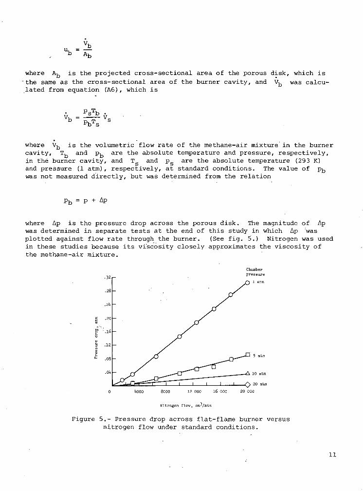
where V^ is the volumetric flow rate of the methane-air mixture in the burnercavity, T, and p, are the absolute temperature and pressure, respectively,in the burner cavity, and T and p are the absolute temperature (293 K)and pressure (1 atm), respectively, at standard conditions. The value of pbwas not measured directly, but was determined from the relation
Pb = p + Ap
where Ap is the pressure drop across the porous disk. The magnitude of Apwas determined in separate tests at the end of this study in which Ap 'wasplotted against flow rate through the burner. (See fig. 5.) Nitrogen was usedin these studies because its viscosity closely approximates the viscosity ofthe methane-air mixture.
B .20 -
S1 M6-
.08 -
.Oh -
0 UOOO 8000 12 000 16 000 20 000
Nitrogen flow, cm-^/min
Figure 5.- Pressure drop across flat-flame burner versusnitrogen flow under standard conditions.
11

An estimate of the error in pj-,, and hence in u ,, was made from an analy-sis presented in appendix B. In this analysis the nitrogen-flow—pressure-dropdata were correlated by a friction-factor—Reynolds number equation for poroussolids, the Kozeny-Carman equation (ref. 21). The resulting correlation wasthen used to estimate pressure drop for assumed average temperatures and reac-tant flow rates in the porous disk. The results of this analysis show that p^could be understated by as much as 12 to 18 percent, depending upon an assumedaverage temperature in the porous disk of 400 K or 450 K. This means that themaximum values ofamount.
UH calculated in this study could be overstated by this
RESULTS AND DISCUSSION
In figures 6, 7, and 8, the reactant velocity is plotted against pressurefor equivalence ratios of 0.7, 0.9, and 1.1, respectively. Each figure showsthe range of reactant velocity for a stable flame, hereinafter referred to asthe stable range. In figures 7 and 8 a dashed line is drawn to represent theadiabatic flame-velocity, or burning-velocity, data of Diederichsen and Wolfhard(ref. 3) for methane-air mixtures in a Bunsen burner. No comparable data areavailable for figure 6. Although there is approximate agreement between these
60
50
toO Stable
• Unstable
*Oo
O§
I I I L_L3 li 5 6
Pressure, atra
8 10
§
8o
i i20 25
Figure 6.- Stable and unstable regions of amethane-air premixed flat flame at variouspressures. 4> = 0.7.
12

70
6o
50
llO
30
20
10
8
*, 5
1;id01
£K
3
2
1
-
-•
•-2
1€
§
^^^•
0o
•oD
— — Flame out
-
-
i1 2
Figure 7.- Stable andpremixed flat flame
6050
140
30
20
10
w 8g •5£ 6-P'u 5o '
S i,JjsS 3Vtc
2
1
•-§
-^T) ^\
i0
I•1
i1 2
O Stable
0 Unstable.
methane-air flames(ref. 2)
•
•
^
"
S1v> ^^
* ^XVQ• 8! o8 8• * §
• i1 1 1 1 1 I I
3 14 5 6 8 10 20 25Pressure, atm
unstable regions of a methane-airat various pressures. <f> = 0.9.
O Stable
0 Unstable
methane-air flames(ref. 2)
\ %
^i
i ^0 • >0
0§ *^ W
? i !• o* •
•
1 1 1 1 1 1 I I3 14 5 6 8 10 20 25
Pressure, atm
Figure 8.- Stable and unstable regions of a methane-airpremixed flat flame at various pressures. <j> = 1.1.
13
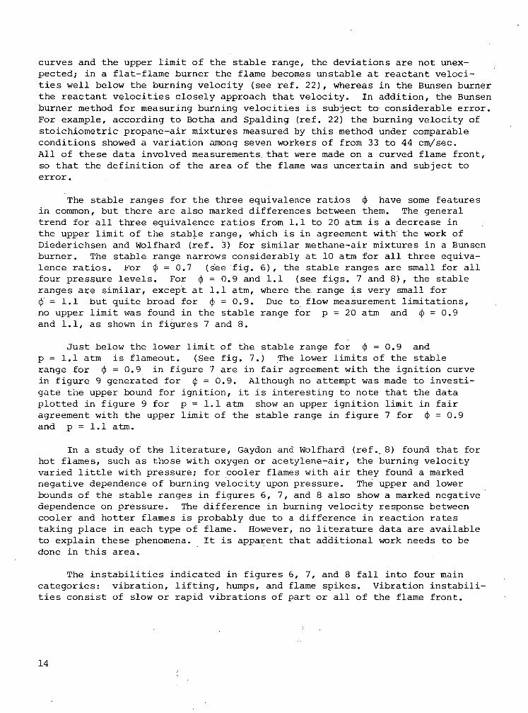
curves and the upper limit of the stable range, the deviations are not unex-pected; in a flat-flame burner the flame becomes unstable at reactant veloci-ties well below the burning velocity (see ref. 22), whereas in the Bunsen burnerthe reactant velocities closely approach that velocity. In addition, the Bunsenburner method for measuring burning velocities is subject to considerable error.For example, according to Botha and Spalding (ref. 22) the burning velocity ofstoichiometric propane-air mixtures measured by this method under comparableconditions showed a variation among seven workers of from 33 to 44 cm/sec.All of these data involved measurements that were made on a curved flame front,so that the definition of the area of the flame was uncertain and subject toerror.
The stable ranges for the three equivalence ratios (j> have some featuresin common, but there are also marked differences between them. The generaltrend for all three equivalence ratios from 1.1 to 20 atm is a decrease inthe upper limit of the stable range, which is in agreement with the work ofDiederichsen and Wolfhard (ref. 3) for similar methane-air mixtures in a Bunsenburner. The stable range narrows considerably at 10 atm for all three equiva-lence ratios. For <|> = 0.7 (see fig. 6), the stable ranges are small for allfour pressure levels. For <J> = 0.9 and 1.1 (see figs. 7 and 8), the stableranges are similar, except at 1.1 atm, where the range is very small for4> = 1.1 but quite broad for tj) = 0.9. Due to flow measurement limitations,no upper limit was found in the stable range for p = 20 atm and <J> = 0.9and 1.1, as shown in figures 7 and 8.
Just below the lower limit of the stable range for <j> = 0.9 andp = 1.1 atm is flameout. (See fig. 7.) The lower limits of the stablerange for <j> = 0.9 in figure 7 are in fair agreement with the ignition curvein figure 9 generated for cj> = 0.9. Although no attempt was made to investi-gate the upper bound for ignition, it is interesting to note that the dataplotted in figure 9 for p = 1.1 atm show an upper ignition limit in fairagreement with the upper limit of the stable range in figure 7 for <j> = 0.9and p = 1.1 atm.
In a study of the literature, Gaydon and Wolfhard (ref. 8) found that forhot flames, such as those with oxygen or acetylene-air, the burning velocityvaried little with pressure; for cooler flames with air they found a markednegative dependence of burning velocity upon pressure. The upper and lowerbounds of the stable ranges in figures 6, 7, and 8 also show a marked negativedependence on pressure. The difference in burning velocity response betweencooler and hotter flames is probably due to a difference in reaction ratestaking place in each type of flame. However, no literature data are availableto explain these phenomena. It is apparent that additional work needs to bedone in this area.
The instabilities indicated in figures 6, 7, and 8 fall into four maincategories: vibration, lifting, humps, and flame spikes. Vibration instabili-ties consist of slow or rapid vibrations of part or all of the flame front.
14

'!
70 -
6050
30
20
o
-Q
O Ignition
n Ho ignition
o
D
No ignition
D
J
It 5 6 8 10
Pressure, atm
20 25
Figure 9.- Ignition conditions for a methane-airpremixed flat flame. ' <J> = 0.9.
Lifting occurs when one side or edge of the flame front lifts away from theburner. Humps are bulges in the center of the flame front, often accompaniedby lifting of one or both sides of the front. A flame spike is a narrow,pointed, orange-colored flame that appears near the edge of the flame front.Below the stable range, the instabilities are of either the vibration or lift-ing type. Above the stable range,, the instabilities include all four types.The lifting, instability observed above the stable range may be explained asfollows. Under stable flame conditions, the reactant gas is cooled more at theperiphery of the.porous disk than at the center, which results in a lower vis-cosity and higher velocity of the gas in that region. For a flame to exist in
15
this higher velocity region, the flame front must curve upward in order thatthe normal component of the stream velocity be equal to the flame velocity. Ifthe normal component of the stream velocity exceeds the flame velocity, theflame will lift away from the burner until the normal component of the streamvelocity is again equal to the flame velocity. This would explain the liftinginstability observed above the stable range. The humps or bulges in the centerof the flame front are not the same as the cellular structure type of insta-bility described by Botha and Spalding (ref. 22) and others; the reason for theobserved instability is not known. Luminous flame spikes appeared near theedge of the flame front at 10 and 20 atm for (j> = 0.9 and 1.1, and at 5 atmfor cj) = 0.7. The fact that these spikes appeared near the edge of the flamefront is suggestive of a low-resistance path for the fuel-air mixture. How-ever, it is not understood why no flame spikes were seen at 10 and 20 atm for<j> = 0.7. Lifting instabilities below the stable range could be the so-called"tilted" flames described by Lewis and Von Elbe (ref. 16).
The foregoing results describe reactant velocity operating ranges as afunction of pressure for stable flat flames of methane-air mixtures for theburner designed and used in this study. These results may not be applicableto another burner having a porous disk of a different size. For example, alarger diameter or thinner disk would be expected to have a greater temperatureand velocity deviation between the center and edge of the disk, as demonstratedby the analytical study of Kihara, Fox, and Kinoshita (ref. 17). These devia-tions could produce smaller stability regions than those reported in thisstudy.
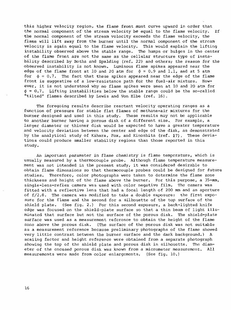
An important parameter in flame chemistry is flame temperature, which isusually measured by a thermocouple probe. Although flame temperature measure-ment was not intended in the present study, it was considered desirable toobtain flame dimensions so that thermocouple probes could be designed for futurestudies. Therefore, color photographs were taken to determine the flame zonethickness and height of the flame above the burner. For this purpose, a 35-mm,single-lens-reflex camera was used with color negative film. The camera wasfitted with a reflective lens that had a focal length of 200 mm and an apertureof f/2.8. The camera was modified to take a double exposure: the first expo-sure for the flame and the second for a silhouette of the top surface of theshield plate. (See fig. 2.) For this second exposure, a back-lighted knifeedge was focused on the shield-plate surface so that a thin beam of light illu-minated that surface but not the surface of the porous disk. The shield-platesurface was used as a measurement reference to obtain the height of the flamezone above the porous disk. (The surface of the porous disk was not suitableas a measurement reference because preliminary photographs of the flame showedvery little contrast between the burner surface and the dark background.) Ascaling factor and height reference were obtained from a separate photographshowing the top of the shield plate and porous disk in silhouette. The diam-eter of the encased porous disk was known from a micrometer measurement. Allmeasurements were made from color enlargements. (See fig. 10.)
16
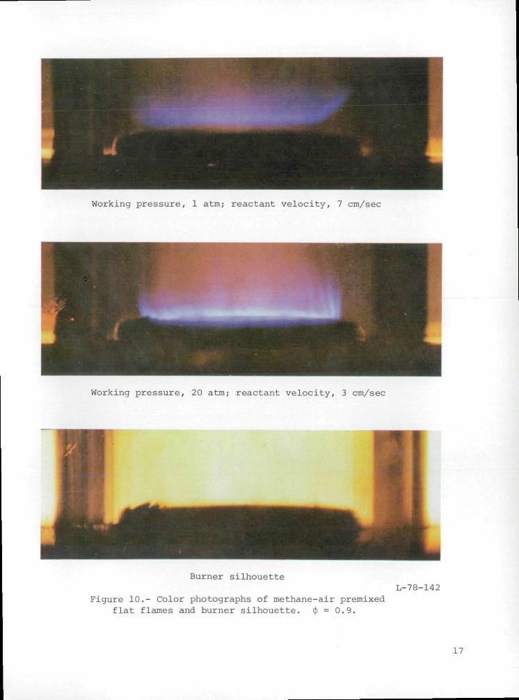
Working pressure, 1 atm; reactant velocity, 7 cm/sec
Working pressure, 20 atm; reactant velocity, 3 cm/sec
Burner silhouette
Figure 10.- Color photographs of methane-air premixedflat flames and burner silhouette. <)> = 0.9.
L-78-142
L7

The data for flame zone thickness are plotted in figure 11 against reac-tant velocity. A separate plot is shown for each equivalence ratio. Theplotted data are for stable flames and show that flame zone thickness variesfrom 0.3 mm at low velocities to 1.2 mm for high velocities. Note that theflame zone thickness for pressures of 10 and 20 atm is in the low range of 0.3to 0.7 mm due to the low velocities associated with the higher pressures. Forgood spatial resolution, thermocouple probes should, in the author's opinion,have a diameter of about 0.1 to 0.2 of the flame zone thickness, or for theseflames, about 0.05 mm. Figure 11 tends to give the impression that flame zonethickness is independent of pressure and equivalence ratio. However, data ofBonne, Grewer, and Wagner (ref. 23) show that the flame zone thickness for amethane-oxygen flat flame is inversely proportional to pressure between 2 and20 torr (1 torr = 0.001316 atm) at constant mass flow rate. Accordingly, theflame zone thickness data of figure 11 were plotted against mass flow rate andcross-plotted against pressure to investigate the possibility of a real varia-tion of flame zone thickness with pressure at constant mass flow rates. This
1.2 -
-.-
-.
''
I
02 6 10 11* 18
Reactant velocity, cm/sec
.•
Figure 11.- Variation of flame zone thickness withreactant velocity.
18
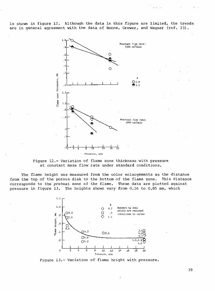
is shown in figure 12. Although the data in this figure are limited, the trendsare in general agreement with the data of Bonne, Grewer, and Wagner (ref. 23).
i.o,—
1 I j I
Reactant flow rate:5300 cm3/min
O0.9
1.5,—
1.0 -
J I5 6
J I
Pressure, atm
Reactant flow rate:3000 cm3/min
J I20 25
Figure 12.- Variation of flame zone thickness with pressureat constant mass flow rate under standard conditions.
The flame height was measured from the color enlargements as the distancefrom the top of the porous disk to the bottom of the flame zone. This distancecorresponds to the preheat zone of the flame. These data are plotted againstpressure in figure 13. The heights shown vary from 0.16 to 0.85 mm, which
1.2 ,—
i.o
.2
ODO
0.7
.9
D8.0
Numbers by datapoints are reactantvelocities in cm/sec
3.0»t.96.7
It.lt.lt.tit.e
10 12Pressure, atm
16 18
Figure 13.- Variation of flame height with pressure,
19

means that a thermocouple probe should be smaller than about 0.03 mm for prob-ing the preheat zone adequately. The number shown beside each data point infigure 13 is the corresponding reactant velocity in cm/sec. Most of the dataassociated with low-reactant velocities have small flame heights, as expected.
CONCLUDING REMARKS
A premixed flat-flame burner was designed for the study of chemical pro-cesses during the high-pressure combustion of methane with the specific goal ofstudying pollutant formation in hydrocarbon flames. The burner was installedin an existing high-pressure facility and was operated successfully withmethane-air mixtures at pressures of 1.1, 5, 10, and 20 atm and equivalenceratios of 0.7, 0.9, and 1.1.
Reactant velocity was used to indicate the range of flame stability. Fora given equivalence ratio, the upper bound of the stable range generallydecreases with increasing pressure. The lower bound for an equivalance ratioof 0.9 corresponds closely to the lower ignition limits for the same equiva-lence ratio, as expected. The results of this study, which describe the rangeof stable reactant velocities, may not be applicable to another premixed flat-flame burner with a porous disk of a different diameter or thickness.
For calculating the reactant velocity in the burner mixing chamber, orburner cavity, the pressure in that cavity was estimated from nitrogen-flow—pressure-drop measurements of the porous disk in the burner. An error analysisof those measurements, based on a friction-factor—Reynolds number correlationfor porous media, indicated that the pressure in the burner cavity, and hencethe reactant velocity, could be in error by as much as 18 percent.
,For the design of thermocouple probes, flame zone thickness and flameheights were measured from color photographs. Flame height is defined as thedistance from the top of the porous disk to the bottom of the flame zone.Flame zone thicknesses ranged from 0.3 to 1.2 mm, and flame heights variedfrom 0.16 to 0.85 mm, which means that thermocouple probes should be on theorder of 0.03 mm or smaller for good spatial resolution.
Langley Research CenterNational Aeronautics and Space AdministrationHampton, VA 23665September 28, 1978
20
APPENDIX A
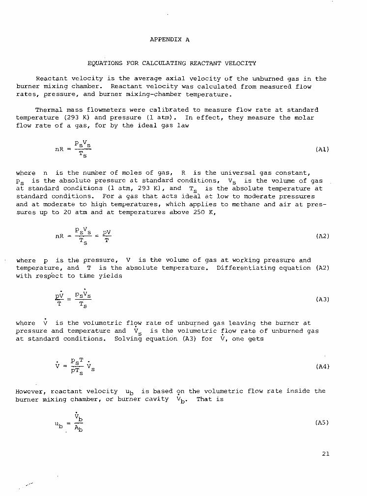
EQUATIONS FOR CALCULATING REACTANT VELOCITY
Reactant velocity is the average axial velocity of the unburned gas in theburner mixing chamber. Reactant velocity was calculated from measured flowrates, pressure, and burner mixing-chamber temperature.
Thermal mass flowmeters were calibrated to measure flow rate at standardtemperature (293 K) and pressure (1 atm) . In effect, they measure the molarflow rate of a gas, for by the ideal gas law
nR = - (Al)
where n is the number of moles of gas, R is the universal gas constant,ps is the absolute pressure at standard conditions, Vs is the volume of gasat standard conditions (1 atm, 293 K) , and TS is the absolute temperature atstandard conditions. For a gas that acts ideal at low to moderate pressuresand at moderate to high temperatures, which applies to methane and air at pres-sures up to 20 atm and at temperatures above 250 K,
where p is the pressure, V is the volume of gas at working pressure andtemperature, and T is the absolute temperature. Differentiating equation (A2)with respect to time yields
(A3)
where V is the volumetric flow rate of unburned gas leaving the burner atpressure and temperature and V is the volumetric flow rate of unburned gasat standard conditions. Solving equation (A3) for V, one gets
. PST .V = -|_ Vs (A4)
However, reactant velocity u^ is based on the volumetric flow rate inside theburner mixing chamber, or burner cavity V^. That is
u, = — (A5)b Ab
21
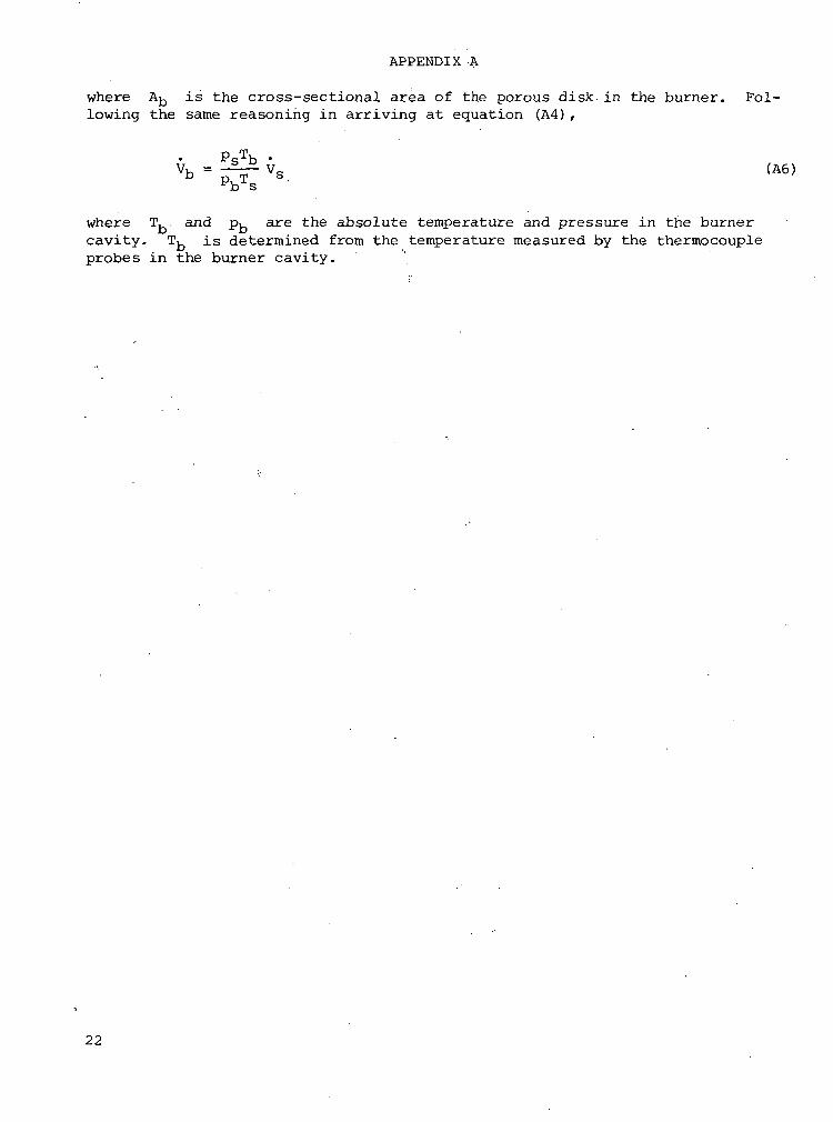
APPENDIX A
where AJ-, is the cross-sectional area of the porous disk in the burner. Fol-lowing the same reasoning in arriving at equation (A4) ,
PSTb •
Vb = -2-£ vs (A6)
where T.. and p^ are the absolute temperature and pressure in the burnercavity. T^ is determined from the temperature measured by the thermocoupleprobes in the burner cavity.
22

APPENDIX B
ERROR ESTIMATE IN PRESSURE OF BURNER CAVITY
The Kozeny-Carman equation for fluid friction in the flow through beds ofsolids (ref. 21) can be written as
Lpu2 (1 - £)s(Bl)
where p., - p^ is the pressure drop in the bed, L is the depth of the bed,p is the density of the fluid, u is the average velocity of the fluid basedon the cross-sectional area of the empty conduit without the bed, e is thevoid fraction or porosity, s and v are the surface area and volume of asingle particle, and f is the friction factor. If the fluid is an ideal gas,then
p =RT
(B2)
where M is the molecular weight of the gas, p is the average pressure of thegas in the bed, R is the universal gas constant, and T is the average abso-lute temperature of the gas in the bed. An expression for u is
V
STsp(B3)
where V is the volumetric flow rate of gas in the bed, S is the cross-sectional area of the bed, which is equal to Aj.,, the projected cross-sectionalarea of the burner, V_ is the volumetric flow rate of gas in the bed at stan-
o
dard conditions, and p and T are the absolute pressure and temperature(293 K) at standard conditions. Substituting equations (B2) and (B3) intoequation (Bl) and rearranging yields
P2 =L(l - 3pP£
T 2 2eJRS Ts Vp
(B4)
Let
£3RS2TS2V
_(B5)
23

APPENDIX B
where C is a constant since the values in this expression are either trueconstants or were constant for this study. With this expression, equation (B4)becomes
Pi - P2 = CMVf|)f (B6)
Solve for f to obtain
Pi - P2(B7)
_
Also, from the Kozeny-Carman equation
f = F(NRe) (B8)
where
Nupvr
Re - £)(B9)
and y is the average viscosity of the gas in the bed.tions (B2) and (B3) into equation (B9) yields
Substituting equa-
NRe = sp(l - £)f PS \MvsVRSTJ
(BIO)
Let
sp(l -PS
= K (Bll)
K is a constant since all the values in this expression are either true con-stants or were constant for this study. With this expression, equation (BIO)becomes
MVCRe (B12)
24

APPENDIX B
Thus, equation (B8) can be written as
(B13)
The values of v and s in equation (Bll) were calculated from amicroscopic measurement of the spherical particles on the surface of theporous bronze disk. The value of £ in this equation was calculated fromthe ratio of the specific volume of bronze to the specific volume of theporous bronze disk, a value furnished by the manufacturer. The correspondingvalues of f and NRe were calculated from equations (B7) and (B12) usingthe nitrogen-flow—pressure-drop data of figure 5 and plotted as shown infigure 14. For the range of NRe from 1 to 10, the f values range from 10to 100. These values of f are higher than those shown by McCabe and Smith(ref. 21) for the same range of NRe/- they show a range of f from 1 to 10.
10'8
65
-I
. 4
I I I
Pressure,atm "
I I I I I I.1 .3 .4 .5 .6 .8 1.0 2
Reynolds number, N3 4 5 6 8 1 0
Figure 14.- Friction-factor—Reynolds number correlationfor the nitrogen-flow—pressure-drop data.
The difference is probably because the values of reference 21 are based on Berlsaddles or rings, a relatively open structure, and the data of this study arefor a porous disk having a very closely packed structure of sintered sphericalparticles 0.13 mm in diameter. The curve of figure 14 should also apply to themethane-air reactant mixture.
25

APPENDIX B
Equation (B12) was then used to calculate NR for a range of Vs forthe reactant mixture, withgiven by the equation
ReM taken at 28 g/mole for the reactants and
y =y(T2)
(B14)
where is the value ofin the burner cavity TV andture
,y at the maximum measured temperature (350 K)y(T2) is the value of y at an assumed tempera-
at the outlet of the porous disk. The two levels of assumedwere 450 K and 550 K, which correspond to average temperatures in the porousdisk of 400 K and 450 K, respectively. With these calculated values of Nj e/figure 14 was used to obtain the corresponding values of f. Then equation (B7)was used in the following form to calculate p, , or pb:
- p22 = 2CMVs
2Tf (B15)
with p2 taken as 1 atm and T defined as
T =Tl + T2
(B16)
The difference between this calculated value of p and the value of p^ deter-mined from the isothermal condition with nitrogen gas can be expressed as apercent error in plf as shown in figure 15.
20
15
10
T! T2 TO 350 450 400
D 350 550 500
0 5000 10 000 15 000 20 000
Volumetric flow rate of gas mixture, cnrVmin
Figure 15.- Percent error in burner cavity pressure orreactant velocity as a function of volumetric flowrate of reactant gas under standard conditions fortwo assumed values of burner exit temperature T2.
26

REFERENCES
1. Edse, Rudolph: Studies on Bunsen Burner Flames at High Pressures WithHydrogen-Oxygen Mixtures. Bull. No. 149, Eng. Exp. Stn., Ohio State Univ.Stud., Eng. Ser., 1952, pp. 441-457.
2. Diederichsen, J.; and Wolfhard, H. G.: Spectrographic Examination ofGaseous Flames at High Pressure. Proc. R. Soc. London, ser. A, vol. 236,no. 1204, July 10, 1956, pp. 89-103.
3. Diederichsen, J.; and Wolfhard, H. G.: The Burning Velocity of MethaneFlames at High Pressure. Trans. Faraday Soc., vol. 52, pt. 8, no. 404,Aug. 1956, pp. 1102-1109.
4. Macfarlane, J. J.; Holderness, F. H.; and Whitcher, F. S. E.: Soot Forma-tion Rates in Premixed C5 and CQ Hydrocarbon-Air Flames at Pressures upto 20 Atmospheres. Combust. & Flame, vol. 8, no. 3, Sept. 1964,pp. 215-229.
5. Strauss, William A.; and Edse, Rudolph: Investigation of Flames Burning atPressures up to 100 Atmospheres. WADC Tech. Rep. 56-49, U.S. Air Force,June 1956.
6. Heberling, P. V.: "Prompt NO" Measurements at High Pressures. SixteenthSymposium (International) on Combustion, Combustion Inst., 1976,pp. 159-168.
7. Miller, Irvin M.; and Maahs, Howard G.: High-Pressure Flame System forPollution Studies With Results for Methane-Air Diffusion Flames. NASATN D-8407, 1977.
8. Gaydon, A. G.; and Wolfhard, H. G.: Flames - Their Structure, Radiationand Temperature. Second ed., Rev. Chapman & Hall Ltd. (London), 1960,pp. 98-99.
9. Zabetakis, Michael G.: Safety With Cryogenic Fluids. Plenum Press, Inc.,1967, p. 57.
10. Barnett, Henry C.; and Hibbard, Robert R., eds.: Basic Considerations inthe Combustion of Hydrocarbon Fuels With Air. NACA Rep. 1300, 1957,pp. 84-87.
11. Friedman, Raymond; and Johnston, W. C.: The Wall-Quenching of LaminarPropane Flames as a Function of Pressure, Temperature, and Air-Fuel Ratio.J. Appl. Phys., vol. 21, no. 8, Aug. 1950, pp. 791-795.
12. Friedman, Raymond; and Johnston, W. C.: Pressure Dependence of QuenchingDistance of Normal Heptane, Iso-Octane, Benzene, and Ethyl Ether Flames.J. Chem. Phys., vol. 20, no. 5, May 1952, pp. 919-920.
27

13. Nair, M. R. S.; and Gupta, M. C.: Measurement of Flame Quenching Distancesin Constant Volume Combustion Vessels. Combust. & Flame, vol. 21, no. 3,Dec. 1973, pp. 321-324.
14. Green, K. A.; and Agnew, J. T.: Quenching Distances of Propane-Air Flamesin a Constant-Volume Bomb. Combust. & Flame, vol. 15, no. 2, Oct. 1970,pp. 189-191.
15. Von Elbe, Guenther; and Lewis, Bernard: Theory of Ignition, Quenching andStabilization of Flames of Nonturbulent Gas Mixtures. Third Symposiumon Combustion and Flame and Explosion Phenomena, Williams & Wilkins Co.,1949, pp. 68-79.
16. Lewis, Bernard; and Von Elbe, Guenther: Combustion, Flames and Explosionsof Gases. Second ed. Academic Press, Inc., 1961, pp. 546-547.
17. Kihara, D. H.; Fox, J. S.; and Kinoshita, C. M.: Temperature and VelocityNon-Uniformity in Edge Cooled Flat Flame Burners. Combust. Sci. &Technol., vol. 11, no. 5-6, 1975, pp. 239-246.
18. Pritchard, Robert; Edmondson, Harry; and Heap, Michael Peter: DiameterEffects in Cooled-Flat-Flame Burners. Combust. & Flame, vol. 18, no. 1,Feb. 1972, pp. 13-18.
19. Spalding, D. B.; and Yumlu, V. S.: Experimental Demonstration of theExistence of Two Flame Speeds. Combust. & Flame, vol. 3, 1959,pp. 553-556.
20. Schlichting, Hermann (J. Kestin, transl.): Boundary-Layer Theory. Sixthed. McGraw-Hill Book Co., 1968, pp. 560, 681.
21. McCabe, Warren L.; and Smith, Julian C.: Unit Operations of ChemicalEngineering. McGraw-Hill Book Co., 1956, p. 95.
22. Botha, J. P.; and Spalding, D. B.: The Laminar Flame Speed of Propane/AirMixtures With Heat Extraction From the Flame. Proc. R. Soc. London,ser. A, vol. 225, no. 1160, Aug. 6, 1954, pp. 71-96.
23. Bonne, U.; Grewer, Th.; and Wagner, H. Gg.: Messungen in der Reaktionszonevon Wasserstoff—Sauerstoff-und Methan—Sauerstoff-Flammen. Z. Phys.Chem. (Neue Folge), Bd. 26, heft 1 and 2, 1960, pp. 93-110.
28

1. Report No.
NASA TP-13182. Government Accession No. 3. -Recipient's Catalog No.
4. Title and Subtitle
A HIGH-PRESSURE PREMIXED FLAT-FLAME BURNER FORCHEMICAL PROCESS STUDIES
5. Report Date
December 19786. Performing Organization Code
7. Author(s)
Irvin M. Miller
8. Performing Organization Report No.
L-12347
9. Performing Organization Name and Address
NASA Langley Research CenterHampton, VA 23665
10. Work Unit No.
505-03-23-01
11. Contract or Grant No.
12. Sponsoring Agency Name and Address
National Aeronautics and Space AdministrationWashington, DC 20546
13. Type of Report and Period Covered
Technical Paper
14. Sponsoring Agency Code
15. Supplementary Notes
16. Abstract
A premixed flat-flame burner was designed and tested with methane-air mixturesat pressures from 1.1 to 20 atm and equivalence ratios from 0.7 to 1.1. Reac-tant velocity in the burner mixing chamber was used to characterize the rangeof stable flames at each pressure—equivalence-ratio condition. Color photo-graphs of the flames were used to determine flame zone thickness and flameheight. The results show that this burner can be used for chemical processstudies in premixed high-pressure methane-air flames up to 20 atm.
17. Key Words (Suggested by Author(s))
Premixed flamesBurnersAir pollutionMethaneHigh pressure
18. Distribution Statement
Unclassified - Unlimited
Subject Category 25
19. Security Oassif. (of this report)
Unclassified
20. Security Classif. (of this page)
Unclassified
21. No. of Pages
28
22. Price*
$4.50
* For sale by the National Technical Information Service. Springfield. Virginia 22161
National Aeronautics andSpace Administration
Washington, D.C.20546
Official Business
Penalty for Private Use, $300
THIRD-CLASS BULK RATE Postage and Fees PaidNational Aeronautics andSpace AdministrationNASA-451 .
U.8.MAIL
NASA POSTMASTER: If Undeltverable (Section 158Postal Manual) Do Not Return