Unified Messaging Speech Recognition Voice Over IP Steve Flagg, Director of Technical Services.

3
A Guideline to the Unified Technical FileRegulations for the Prevention of
Air Pollution from Ships
First Edition, Nov. 2004

4

5
Preface
This booklet is intended for Licensees, ship operators, shipyards, and marine engineers in general toillustrate the Unified Technical File designed for all MAN B&W engines – required to meet the IMOregulation for the prevention of air pollution.
The Unified Technical File is a document that specifies a procedure, mainly based on performancemeasurements, by which the operator can verify compliance with the IMO ‘NOx Technical Code’ to theFlag State Authority (or their representative) when the engine is later checked in service.
MAN B&W Diesel has designed this booklet partly to explain survey procedures and partly as a look-up manual for IMO definitions. The first part concentrates on survey routines, from testbed to on boardsituations (the most important for the operator), describing the survey from start to finish. The secondpart expands on specific subjects and how to handle the most common tasks on board, e.g. the spareor reconditioning parts covered by the regulation.
Regarding general emission questions or emission control of MAN B&W two-stroke engines, referenceis given to existing material issued by MAN B&W Diesel.

6

7
Contents
A. Guidelines to the Unified Technical File (TF) ............................................... 11Introduction ............................................................................................ 12Advantages ............................................................................................ 13TF design ............................................................................................... 14Component changes ............................................................................. 15Adjustments ........................................................................................... 16Summary ............................................................................................... 16Concept (engine categories) ................................................................. 17
B. Survey Methods .......................................................................................... 18IMO survey of Parent Engines on Testbed ............................................ 19Survey of Member Engines on Testbed ................................................ 22Survey on Sea Trial ................................................................................ 25On-board Survey ................................................................................... 27
C. Case Story ................................................................................................... 31
D. Glossary ....................................................................................................... 32IMO Annex VI ......................................................................................... 32Engines covered by the IMO NOx regulation ........................................ 33Vessels covered by the IMO SOx regulation ......................................... 34Emissions regulated .............................................................................. 35NOx limits ............................................................................................... 36The IMO NOx Technical Code defines three categories of engines ..... 37Performance parameters ...................................................................... 38

8
Local areas ............................................................................................ 39Required IMO NOx component marking ............................................... 40Licensee’s own numbering .................................................................... 54Emissions from non-IMO engines or for other purposes ...................... 55
E. Description of Documents ........................................................................... 56Pre-certificate ........................................................................................ 57TF ........................................................................................................... 58On-board Survey ................................................................................... 59Engine parameter check method .......................................................... 60Parameter survey .................................................................................. 61Survey code........................................................................................... 62Record Book of engine parameters ...................................................... 63
F. Parameters in the Document ...................................................................... 64IMO ID-number ...................................................................................... 65Performance tolerances ........................................................................ 66Performance reference values .............................................................. 67Engine setting values............................................................................. 68Changing of setting values .................................................................... 69Influence on engines in operation ......................................................... 70Spare parts ............................................................................................ 71Major conversions ................................................................................. 73Substantial modifications ...................................................................... 74Amendments ......................................................................................... 75

9
Reconditioning of engine parts ............................................................. 76Maintenance on an IMO engine ............................................................ 77Simplified measurement method .......................................................... 78Continuous On-board monitoring .......................................................... 79Is continuous On-board emission monitoring needed? ........................ 80
G. Responsibilities ............................................................................................ 81Licensee’s responsibilities ..................................................................... 82Yard’s responsibilities ............................................................................ 83Owner’s responsibilities ......................................................................... 84
H. Other ............................................................................................................ 85ME engines ............................................................................................ 86Future regulations .................................................................................. 87
I. Assistance from MAN B&W Diesel .............................................................. 89
J. Overview of Survey Routines ...................................................................... 90

10

11
A
In connection with the International Maritime Organization (IMO) Annex VI of Marpol 73/78 –Regarding the Prevention of Air Pollution from Ships, MAN B&W Diesel has prepared the followingguidelines to a unified technical file.
A. Guidelines to the Unified Technical File (TF)
Purpose:
1. To ensure that MAN B&W two-stroke engines are tested and can be surveyed inaccordance with IMO Annex VI.
2. To inform shipowners and operators about the TF and how to comply with Annex VI by usingthe unified MAN B&W Diesel standard.
Questions or comments regarding the guidelines should be directed to Dept. 2110, Standardsand Classification, see page 89.

12
Introduction
The IMO has introduced a new Annex VI of MARPOL 73/78, concerning regulation for the preventionof air pollution from ships. Annex VI applies to all engines delivered since 1 January 2000, and entersinto force 19 May 2005.
MAN B&W Diesel has worked with the licensees and classification societies to find a uniform designfor the TF – required under IMO Annex VI, in order to survey on board compliance.
Many of the first TFs produced by the engine builders varied due to different demands made by thedifferent classification societies. This happened because the IMO Annex VI does not give sufficientlydetailed instructions on how to draw-up the TF in practice.
MAN B&W Diesel has assumed the task of coordinating the work to prepare a uniform TF, to be usedboth by the licensees and the classification societies. The task also includes the necessary proceduresfor shipowners when later engine adjustments or changes of components have occurred.

13
A
Advantages
The unified TF means:
• Certainty of market acceptance of the TF• Satisfied customers, who can show engine compliance when checked at sea by the Flag
State representatives• A survey method based on principles familiar to the crew• More engines can be accepted within the same engine Group, meaning reduced expenses• Less money spent on emission measurements.
Parent engines can be shared between MAN B&W Diesel and the licensees. This will greatly reducethe number of emission measurements and future certification costs.

14
TF design
The principle of the MAN B&W Diesel unified concept is that the defined ‘NOx components’ andperformance data (measurement of pmax, pcomp, Tscav and pback) can show that an engine complies withthe NOx limit.
Some licensees have, in the past, used a component setting tolerance instead of performance data.However, if the operator has adjusted the engine, the engine might be out of compliance when theengine is later checked by the Flag State for compliance at sea.
Only extensive tests on Testbed can validate engine adjustments when component settings tolerancesare used. It is important to note that when IMO Annex VI is ratified, the focus will be on follow-up atsea – where changes and adjustments will take place.
Some licensees have selected to use their own developed TF instead of the recommended MAN B&WDiesel common component ID numbers. This will make it much more difficult for the owners topurchase spare parts in the future, and still stay in compliance with the IMO regulation.
It is predicted that some engines already delivered will not be in compliance when they are surveyed.We suggest that all owners who have made changes to their engines contact the manufacturerregarding its status, before IMO Annex VI comes into force.

15
A
Component changes
This unified TF will allow changes of the engine’s NOx components, while maintaining compliance incases where a shipowner changes components at sea.
Some owners have already demanded a unified system in order to avoid working with different TFs.

16
Adjustments
The unified TF will allow all adjustments on board within the stated performance parameters.
Summary
The Unified TF is the standard introduced by MAN B&W Diesel and it is accepted by the classificationsocieties’ headquarters. It should be followed by the licensees for all future engines.

17
A
Concept (engine categories)
The IMO Annex VI NOx technical code defines three categories of engines:
1. Individual Engines2. Engine Groups3. Engine Families
Individual engines are handled on the Testbed in the same way as a Parent engine. However, a Groupdefinition is not included in the TF.
Engine Groups and engine Families consist of a Parent engine and a number of Member engines. AllTwo-stroke engines can be defined in an engine Group, either as the Parent engine (representing theMember engines) or as a Member engine.
Most of the survey procedures made for the Member engines and the Parent engine application arethe same. The difference for Member engines is that the emission testing is not necessary – neither onTestbed nor at sea.

18
B. Survey Methods
The survey methods include Testbed, Sea Trial and On-board inspections. The flow chart for surveymethods has been split up into different sections to make a more detailed description. Refer to Fig. B1,Appendix B in the TF.

19
BSurvey Start
SurveyType
Testbed: Inspection ofPre�Technical File (EIAPP)
EngineType
Performance andComponent approval
Survey FinishSign Documents
Adjust
Yes
No
Performance Check:a) measure performanceb) measure NO
c) check fuel nozzle andECS version
d) other NO componentse) verify settings
x
x
NO components Check:x
1. Parent Engine
1) IMO survey of Parent Engines on Testbed

20
The performance parameter check is the basis of the survey methods. The measurements involved areused as reference for Member engines.
Note. A change in performance usually means a change in the NOx level.
Performance Check:
a) measure performanceb) measure NOx
‘NOx component’ Check:
c) check fuel nozzle and ECS version (for ME engine types)d) check other NOx componentse) verify settings

21
Ba+b) Performance and NOx measurements:
pmax, pcomp, Tscav and pback and NOx measured (and corrected) at the four load points inaccordance with the E2/E3 IMO cycle.
c) The Electronic Control System (ECS) software is important for correct operation of the engineand, therefore, the emission levels.To extend the group of engines that can be associated with a Parent engine, different types offuel nozzles are tested for different engine types.
d) Approved IMO compliant NOX components are listed in the engine TF (or pre-TF).
e) The setting values are verified for guidance only and are not a verification of the engine’s actualNOx emission level. The value includes the ‘IMO Chief Checksum’ value on the Main OperatingPanel for the ME engine types. The values are to be used only as guideline indications for lateradjustments after, for example, overhauls comprising the fuel cam or exhaust cam position.
A survey code is established by data gained from the official Testbed tests in order to ease an onboard survey. The results, therefore, cannot be printed until later – together with the EIAPP applicationwith the Parent TF.
22
Survey Start
SurveyType
Testbed: Inspection ofPre�Technical File (EIAPP)
EngineType
Survey Finish
Performance andComponent approval
Sign Documents
Adjust
Yes
No
2. Member Engine
Performance Check:a) measure performanceb) verify performance
c) check fuel nozzle and ECS versiond) other NO componentse) verify settings
Print out survey code tables(with EIAPP application)
NO components Checkx
x
2) Survey of Member Engines on Testbed

23
BThe main difference between surveying Parent and Member engines is that the NOx emission is onlybeing measured for the Parent engine. For the Member engine, the performance check verifiescompliance based on the parent engine NOx data.
Performance Check:
a) measure performanceb) verify performance (Testbed version)
‘NOx component’ Check:
c) check fuel nozzle and ECS version (for ME engine types)d) check other NOx componentse) verify settings
Print out survey code tables

24
a) Performance measurements:
pmax, pcomp, Tscav and pback are measured (and corrected) at the four E2/E3 load points.
b) Verify performance:
The survey code (Testbed version), which is based on the Parent engine data willautomatically correct the performance values and perform a NOx estimate when performancemeasurements and ambient conditions are entered into the program.
If the ISO ambient corrected performance values are within the TF specified tolerances, theengine is in compliance with the IMO regulation.
c+d) The approved IMO NOx components are listed in the engine TF.
e) The setting values are verified for guidance only, and are not a verification of the engine’s actualNOx level. The value includes the ‘IMO Chief Checksum’ value on the Main Operating Panel forthe ME engine types. The values are to be used only as guideline indications for lateradjustments after, for example, overhauls comprising the fuel cam or exhaust cam position.
The survey tables document the survey and are printed for later reference and are included in theMember engine’s TF.

25
B
Survey Start
SurveyType
Inspection of:Technical File (IAPP)
Adjustment orComponent Changes
Survey Finish Sign Documents and add to Record Book
No
3. Sea Trial
NO components Checkx
c) check fuel nozzle and ECS versiond) other NO components
(as considered necessary)e) verify settings
(as considered necessary)
Print out survey tables
x
3) Survey on Sea Trial
(without component or adjustment changes)

26
A NOx component check is sufficient to verify that the engine is in compliance.
All documentation established so far, including the certificate, TF and eventual Record Book (seeChapter E for definition of Record Book) should be inspected, and the outcome should be included inthe IAPP documentation for later reference on board.
‘NOx component’ Check:
c) check fuel nozzle and ECS version (for ME engine types)d) check other NOx components (when considered as necessary)e) verify settings (when considered as necessary)
Print out survey code tables to document compliance.
If changes to components or settings were introduced,see survey method 4 (On board survey).

27
B
Survey Start
SurveyType
Inspection of:Technical File and Record Book
Adjustment orComponent Changes
Survey Finish Sign Documents and add to Record Book
Adjust
Performance andComponent approval
Yes
YesNo
4. On�board Survey
Performance Check:a) measure performanceb) verify performance (VIT or non-VIT)
c) check fuel nozzle and ECS versiond) other NO components
(as considered necessarye) verify settings
(as considered necessary)
Print out survey tables
NO components Checkx
x
4) On-board Survey
(to be used when adjustments have been made to components or settings)

28
All established documentation (EIAPP, TF, IAPP and eventual Record Book) must be inspected. Theoutcome must be filed in the on board Record Book for later reference.
Performance Check:
a) measure performanceb) verify performance (onboard VIT or non-VIT versions)
‘NOx component’ Check:
c) check fuel nozzle and ECS version (for ME engine types)d) check other NOx components (when considered as necessary)e) verify settings (when considered as necessary)
Print out survey code tables to document compliance.

29
Ba) Performance measurements:
For engines with VIT, the 75% load point and one load point above the VIT break point are to bemeasured. For engines without VIT, and the ME engine types, only the 75% load point ismeasured (the performance data measured are as stated above).
b) Verify performance:
The survey code (on board version), which is based on the Parent engine data will automaticallycorrect the performance values and perform a NOx estimate when performance measurementsand ambient conditions are entered into the program.
If the ISO ambient corrected performance values are within the TF specified tolerances, theengine is in compliance with the IMO regulation.
c) The fuel nozzle, being the component having most influence on NOx, must be checked byidentification of its ID number, as well as the ECS version for the ME engine types.
d) The Flag State representative can check other NOx components, when considered asnecessary, by identification and comparison with the TF component ID numbers.

30
e) The setting values, comprising the fuel cam and exhaust cam positions and the ‘IMO ChiefChecksum’ values on the Main Operating Panel (for the ME engine types), may be verified,when considered as necessary by the Flag State representative. However, the values are forguidance only.
Note. Three versions of the on board survey code exist – depending on the engine fuel pump system(VIT, non-VIT or ME).
The survey tables document the survey and are printed for later reference and included in the ‘RecordBook’.

31
C
C. Case Story
An engine Group was established on the basis of the Parent engine tested as engine No. 1. Memberengine No. 2 was delivered in agreement with the established TF, but for Member engine No. 3 it wasdecided to perform comparison tests for a new fuel nozzle.
1. Parent engine2. Member engine3. Member engine (new fuel nozzle tests)4. Member engine
Two different possibilities exist for maintaining the engine Group certificates:
The new fuel nozzle can be added to the TF with an amendment for the nozzle, but only if the newnozzle demonstrates a lower NOx value than the original fuel nozzle.
A new engine Group can be established on the basis of engine No. 3 as a new Parent engine (if theengine was surveyed as a Parent engine on Testbed). In this case, new Member TFs for the previousMember engine need to be established.
Engine No. 4 can be certified to either engine Group depending on the fuel nozzle used (provided thatboth nozzles are entered in the TF).
A detailed description of the survey methods can be found in the TF (Chapter 3 and Appendix B).

32
D. Glossary
IMO Annex VI
The IMO Annex VI is a new annex to MARPOL 73/78 – the International Convention for the Preventionof Air Pollution from Ships – and which applies to every ship of 400 gross tons and above.
The rules on NOx emission are specified in Conference Resolution 2, the NOx Technical Code.

33
D
Engines covered by the IMO NOx regulation
1. All diesel engines with an output of more than 130kW and installed in a ship built on or after1 January 2000.
2. All engines (above 130kW) that undergo a major conversion:
• an engine replaced by a new engine built on or after 1 January 2000• any substantial modification, as defined in the NOx Technical Code, made to the engine, or• the engine rating (MCR) is increased by more than 10%
Emergency engines and Navy vessels are not covered by IMO, and engines entirely for use in internalState waters are not covered if an alternative NOx control measure is applicable.

34
Vessels covered by the IMO SOx regulation
All.
35
D
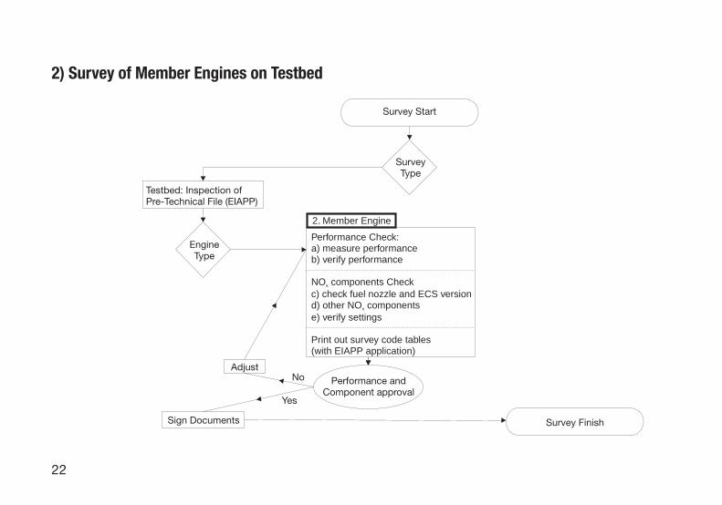
Emissions regulated
NOx: Regulation 13 describes a speed-related IMO NOx limit (from 17gNO2/kWh to 9.8gNO2/kWhdepending on rated engine speed or an exhaust gas cleaning system which provides an equivalentNOx reduction).
SOx: Regulation 14 describes the sulphur limit. The sulphur content of the fuel shall not exceed 4.5%.In defined SOx control areas, an HFO fuel with equal or less than 1.5% sulphur content, or an after-treatment system that limits the exhaust SOx to equal or less than 6gSO2/kWh are required. Todocument the sulphur content in the fuel, a new bunker delivery note is required, accompanied by arepresentative sample of the fuel oil delivered, as specified in Regulation 18.
However, individual countries (Flag States) may have special mandatory or voluntary requirementswithin local waters, and certain businesses require information on different emission components.

36
NOx limits
The MAN B&W Diesel unified TF specifies three NOx values:
1. The MCR speed-related IMO NOx limit (see previous)2. The actual Parent engine reference NOx value3. The actual Parent engine NOx value at maximum tolerance conditions.
The last value must be less or equal to the IMO NOx limit to comply with the IMO Annex. However, forOn board surveys, the simulated Member engine NOx value must be less than the Parent enginemaximum value (with allowed tolerances).

37
D
The IMO NOx Technical Code defines three categories of engines
1 Individual engines2 Engine Groups3 Engine Families
Engine Groups and Families consist of a Parent engine and a number of Member engines.
Large two-stroke engines belong to either category 1 or 2 because of the necessity for adjustments onboard.
In principle, most of the survey procedures made for the Individual and the Parent engine applicationwill be the same. The main difference for Member engines is that the emission testing is not required –neither on the Testbed nor at sea.
The more engines that can be included in the same engine Group, the easier and lower the costs forthe engine builder. Furthermore, having a Unified TF will facilitate sharing of engine Groups amongMAN B&W Diesel and the engine builders, saving more costs.

38
Performance parameters
Following extensive testing, MAN B&W Diesel has established the NOx sensitivity of differentperformance parameters. This knowledge has been utilised to establish the defined allowed maximumIMO tolerances. These tolerances must be met always, independent of (or in addition to) the specifiedservice tolerances in the instruction books for the engine.

39
D
Local areas
SOx emission control areas (SECA).
IMO defined area with a SOx limit of 1.5%.
Note. The Baltic Sea and the North Sea have been defined as special restricted-SOx areas.

40
Required IMO NOx components marking
MAN B&W Diesel has defined 12 standard engine components as IMO NOx components that mightinfluence the NOx emission.
A listing of the components (including a few major sub supplier components: T/C, charge-air cooler,auxiliary blower and the governor) is given in Table 1.1 in the TF together with the allowed ID numbers.
The marking position on each component is described in the TF’s Appendix A and is specified in astandard MAN B&W Diesel marking specification.
Except for the fuel nozzle, none of the defined IMO components are easy to replace with a differentdesign and, consequently, are not likely to change the NOx characteristics. Therefore, if the engineperformance is kept within the specified tolerances (see TF Table 1.3) the engine will comply with theIMO limit.
Only the nozzle ID number might need verification (this is always at the discretion of the surveyor). ForME engines, the Electronic Control System (ECS) version and the selected engine mode also need tobe surveyed.
MAN B&W Diesel has defined the ‘Part Number’ as the IMO ID number for the component. Many ofthe defined NOx components are already stamped with the part number.
Note. Only the main part number is used – not the revision number (see circled number in TF Appendix A.)

41
D
Part Certified Marking Required Marking NotesMarking Instruction
Cylinder liner Part Mo. 0742637-8 Either manufacturer’s Name Marking is onor Trademark, plus Part No. manoeuvring side
42
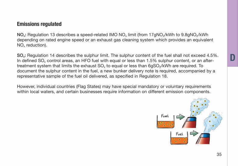
Part Certified Marking Required Marking NotesMarking Instruction
Cylinder cover Part No. 0742634-2 Either manufacturer’s Name Marking is onor Trademark, plus Part No., manoeuvring sideYear and Week of manufacture

43
D
Part Certified Marking Required Marking NotesMarking Instruction
Piston crown Part No. 0743260-7 Either manufacturer’s Name Marking is onor Trademark, plus Part No. manoeuvring side

44
Part Certified Marking Required Marking NotesMarking Instruction
Fuel pump Part No. 0742843-8 Manufacturer’s Name On ME engines:barrel or Trademark, plus Part No., The barrel and the
and Engine Type plunger are paired

45
D
Part Certified Marking Required Marking NotesMarking Instruction
Fuel pump Part No. 0742845-1 Manufacturer’s Name On ME engines:plunger or Trademark, plus Part No. No marking required.
and Engine Type

46

47
D
Part Certified Marking Required Marking NotesMarking Instruction
Fuel cam Part No. 0742636-6 Either manufacturer’s Name Marking is onor Trademark, plus Part No. Bearing side
Exhaust cam Part No. 0742635-4 Either manufacturer’s Name Marking is onor Trademark, plus Part No. Bearing side
Inserted pictures shows marking example

48
Part Certified Marking Required MarkingMarking Instruction
Fuel nozzle Part No. 0742639-1 Manufacturer’s Nameor trademark, plus Part No.,and hole diameter (mm)
Marking Location

49
D
Part Required Marking Notes
Scavenge air Manufacturer’s Name, Type, Marking is oncooler Contract number, Name Plate
Year of manufacture,Water side and Air side figuresfor: Op. Exc. Press. (bar),Test Exc. Press. (bar),Op. Temperature (oC) andContent (L)

50

51
D
Part Required Marking Notes
Turbocharger Manufacturer’s Name, Type, Marking is onSerial number(s), Name PlateManufacturing date,Specification, T/C manufacturer isMax. cont. speed and responsible forMax. cont. gas temperature marking 4 internal
components andissues a specific IMOcertificate for the T/C

52
Part Required Marking Notes
Auxiliary Manufacturer’s Name, Model, Marking is onblower Capacity, Pressure, Temp., Name Plate
Density, Serial number(s),Speed, Power, Date of buildand Electrical Source.

53
D
Part Notes
Governor Manufacturer/Installer isresponsible formarking

54
Licensee’s own numbering
Some licensees have introduced their own IMO ID numbering system. However, the MAN B&W DieselID number is always required along with the licensee number in the TF.
The ME engine has certain different components, but the On board survey exactly follows sameprocedures as for the MC engine.

55
D
Emissions from non-IMO engines or for other purposes
Engines that do not fall within the IMO regulation (i.e. ‘old engines’ built before 1 January 2000) are notrequired, from the IMO point of view, to document the emission characteristics.
Incentives from individual states or customers may urge Owners to obtain actual emission values.
It is possible, but very difficult, to measure emissions on board for different Flag State/customerpurposes. The specific requirements (components and accuracies) should be stated clearly. The shipOwners will have an obligation to ensure safe access for personnel and provide the equipment andexhaust sampling gear necessary for taking the measurements.
On board IMO engine certification should only be carried out if absolutely necessary. In order to obtainan EIAPP certificate after installation on board, the engine must be certified either as an Individualengine or an engine Group. In principle, most of the survey procedures made for the Individual and theParent engine application will be the same.
The measurement procedures must follow normal Testbed procedures (for measurements and loadcycle) and without any tolerance allowances.
For IMO-compliant engines, all gaseous emission must be stated (at the four load points in the E2/E3cycle) in Chapter 4 of the TF (for the common MAN B&W Diesel TF).

56
E. Description of Documents

57
E
Pre-certificate
The interim Engine International Air Pollution Prevention Certificate (EIAPP) is the legal document thatapproves the engine on the Testbed in accordance with the NOx Code and Regulation 13 of Annex VI.
This preliminary or interim certificate (‘statement of compliance’) will only be issued until theenforcement date of 19 May 2005, and will have to be exchanged with a final EIAPP certificate sinceAnnex VI has been ratified.
All of the original documents must be available on board at all times.

58
TF
An approved document that specifies the actual engine’s performance data, the engine Group (anumber of engines defined by the engine with the highest NOx emission – the Parent engine), theemission characteristics of the Group, and how to survey the engine on board for NOx compliance.
MAN B&W Diesel has introduced a Unified TF as the standard common TF set-up for all MAN B&WDiesel Two-stroke engines. This was done in order to simplify the IMO Annex VI for Owners and toensure similar TFs for all MAN B&W Diesel engines, independent of the various licensees.
To ensure compliance with the MAN B&W Diesel standard, an example of a Unified TF can beobtained by contacting Department 2110.

59
E
On-board Survey
A survey of the engine, as defined in the TF, to verify continuous compliance with the NOx emissionlimits of IMO Annex VI.
Different survey methods are specified in the IMO NOx Technical Code – dependent on the purpose ofthe survey (pre-certification survey on Testbed, initial survey on board or, periodical or intermediatesurveys on board).

60
Engine parameter check method
MAN B&W Diesel has defined an Engine Parameter Check Method as a combination of a performanceparameter check and a component survey (see Service Letter No. SL03-428).
The On board survey is described in detail in TF, Chapter 3, and Appendix B, Fig. B.1. This presents anoverview of the different mandatory survey procedures.

61
E
Parameter survey
A manufacturer defined survey procedure.
MAN B&W Diesel has defined four performance parameters for the On board survey for verification ofengine compliance with the IMO NOx regulation:
• maximum pressure• maximum compression pressure• scavenge air temperature• turbocharger backpressure.
To verify compliance, these parameters (adjusted to ISO ambient conditions) must stay within thetolerances specified in TF, Table 1.3.
The survey follows standard MAN B&W Diesel procedures for engine performance checks (see TF,Appendix B). However, for scheduled surveys, all sensors and gauges used in the survey code mustbe reliable and calibrated in accordance with the manufacturers specifications (and the IMO NOx
Technical Code requirements).

62
Survey code
A dedicated code for the actual engine Group that facilitates easy On board surveys.
In connection with the On board survey (see TF, Chapter 3 and Appendix B), MAN B&W Diesel hasintroduced a small Microsoft® Excel® code that, automatically, either shows compliance, or points tonecessary adjustments of the engine setting/performance values.
When the engine is surveyed (Testbed or On board), the setting values are measured in accordancewith the procedures in the instruction book, and documented through the survey code, which isprinted out to the Record Book. The performance parameter survey automatically approves the settingvalues. For MAN B&W two-stroke engines, these are for guidance only (i.e. for use in cases where theperformance data can not be obtained – e.g. during docking).
When using the MAN B&W Diesel-defined on board parameter survey method for large two-strokeengines, the setting values are for guidance only. For other survey methods, either TF-definedtolerances (based on additional measurements for the individual settings) or amendments arenecessary.
The actual readings are registered in the survey code for future reference.

63
E
Record Book of engine parameters
An Owner-established ‘log book’ to document any changes (including recorded On board surveys) toIMO components or engine settings that may influence NOx emissions.
With a few modifications, the standard on board ‘log book’ can be used as the Record Book.
Together with the TF, MAN B&W has introduced a survey code that lists the necessary documentationfrom the On board survey to be included the Record Book.

64
F. Parameters in the Documents

65
F
IMO ID-number
A manufacturer specified unique number for an engine component that may have an influence on theengine NOx emission characteristics.
MAN B&W Diesel has defined the ‘Part Number’ as the IMO ID-number for the component. Many ofthe defined NOx components (MAN B&W Diesel has defined 12 standard engine components as IMONOx components) are already stamped with the Part Number. However, only the main Part Number isused – not including the revision digit (see encircled number in TF, Appendix A).
Some licensees have introduced their own IMO ID-number system. However, the MAN B&W DieselID-number is always required along with the licensee number in the TF. Components with any one ofthe numbers defined in TF, Table 1.1 are valid.
Only the components marked with an IMO ID-number and specified in TF, Table 1.1 (or in thededicated survey code for the engine Group) are accepted as common replacement spare parts.
New components or modified spare parts to replace the existing component (i.e. components with adifferent IMO ID-number) must be amended to the TF. MAN B&W Diesel are responsible for ensuringthat original spare parts can be used on board.
Always make sure that MAN B&W Diesel ID-numbers are added to the licensee’s TF in order to obtainthe flexibility for purchasing and updating parts.

66
Performance tolerances
The tolerances defined in TF, Table 1.3 for the four performance parameters that affect the engine NOx
emission characteristics.
Following extensive testing, MAN B&W Diesel has established the NOx sensitivity of differentperformance parameters (maximum pressure, maximum compression pressure, scavenge airtemperature and turbocharger backpressure). This knowledge has been utilised to establish thedefined allowed maximum IMO tolerances. These tolerances must be met always, independent of (orin addition to) the specified service tolerances in the instruction books for the engine.
67
F
Performance reference values
The ‘ideal’ Parent engine performance reference values are defined in TF, Table 1.3.
When the Parent engine is run on the Testbed, ambient conditions and, perhaps, not preciselyadjusted engine setting values may lead to slightly ‘off-performance’ values. This is normal, thereforeto define the engine Group in the best possible way, a set of slightly different values – the performancereference values – has been defined. The engine NOx emission is now corrected to reflect thiscondition, just as the NOx emission is corrected to ISO ambient conditions.

68
Engine setting values
Mechanical or electrical adjustment features of the engine providing certain engine performancecharacteristics.
When the engine is surveyed (Testbed or On board), these values are measured (following theprocedures in the instruction books) and documented through the survey code (and printed out to theRecord Book). With a few modifications, the standard ‘log book’ on board can be used as the RecordBook. The performance parameter survey automatically approves the engine setting values, which forMAN B&W two-stroke engines are for guidance only (i.e. for use in cases where the performance datacannot be obtained, e.g. during docking).
Adjustment of the ME engine setting values is done on the Engine Control System panel and verifiedby means of ‘checksum’ values. Two checksums are defined for emissions, an ‘IMO Designchecksum’ and an ‘IMO Chief checksum’. The IMO Chief checksum is verified (and approved) throughthe On board parameter survey, whereas the ‘IMO Design checksum’ is a manufacturer responsibility,which might require an amendment to be in compliance. This amendment usually consists of one pagereferring to engine Group, engine Type, and the authorised company approval number introducing anew IMO ID-number on a component.

69
F
Changing of setting values
Setting values can be changed, depending on the survey method as defined in the TF.
The actual readings are registered in the survey code for future reference.
When the engine is surveyed (Testbed or On board), these values are measured (following theprocedures in the instruction books and documented through the survey code (and printed out to theRecord Book). The performance parameter survey automatically approves the setting values, which forMAN B&W two-stroke engines are for guidance only.

70
Influence on engines in operation
Modifications to engine are allowed within IMO defined constraints.
IMO Annex VI uses specific definitions related to engine modifications (spare parts, major conversionand substantial modification).

71
F
Spare parts
Always use spare parts from authorised MAN B&W Diesel spare part suppliers and drawings.
Only the components marked with an IMO ID-number and specified in TF, Table 1.1 (or in thededicated survey code for the engine Group) are allowed as common replacement spare parts.
New components or modified spare parts to replace the existing components (e.g. components with adifferent IMO ID-number) must be amended in the TF. The amendment usually consists of one pagereferring to an engine Group, engine Type, and the authorising company (Classification Society)approval number introducing a new IMO ID-number on a component.

72
MAN B&W Diesel is responsible for ensuring that original spare parts can be used on board.
New IMO NOx components will be filed by MAN B&W Diesel with the class societies when engineGroups (using the unified TF set-up) are filed to MAN B&W Diesel. This will require that our licenseesreport back to MAN B&W Diesel regarding introduced engine Groups.
Always make sure that MAN B&W Diesel ID-numbers are added to the licensee TF, in order to obtainflexibility when buying and updating parts.

73
F
Major conversions
As defined in IMO Annex VI, Regulation 13:
• When the engine is replaced with a new engine (built after 1 January 2000)• When the engine undergoes a substantial modification• When the MCR rating is increased by more than 10%.
In cases of a major conversion of an ‘old’ engine (an engine built before 1 January 2000), this enginemust now fully comply with Annex VI, Regulation 13.
Engines that already comply with the Regulation 13 might, in the worst case, need a new Parentengine, but in most cases, an amendment will be sufficient.
Engines that are derated (e.g. by more than 10%) might have a change in their emissioncharacteristics (possibly, increased NOx emissions) and, therefore, also be considered as a majorconversion.

74
Substantial modifications
For ‘IMO compliant’ engines where the modification will increase the NOx emission level to exceed theIMO limit set out in Regulation 13 of Annex VI, and for ‘old’ engines where the modification increasestheir existing NOx emission level beyond the tolerances allowed for a simplified measurement method.
Due to the difficult conditions for taking measurements on board, certain measurement tolerances areallowed in connection with this method (see NOx Technical Code §6.3.11), e.g. 10% due to themeasurement method and 10% due to the possibility of a different fuel, but maximum of 15% in total.
For compliant engines, if the Parent engine’s maximum NOx tolerance is exceeded, a new Parentengine must be introduced.
For ‘old’ engines, if NOx increases, it would require major efforts (if possible at all) to establish a TF andcertify the engine on board. Fortunately, most modifications (introduction of new techniques andtechnologies) will reduce emissions and, therefore, not result in a requirement for the engine to complywith the IMO regulation.

75
F
Amendments
An amendment is the formal instrument to introduce changes to the original IMO components andsettings defined in the engine’s TF.
The amendment usually consists of one page referring to the engine Group, engine Type, and the FlagState representative approval number introducing a new IMO ID-number.
For new Members to an existing engine Group to which amendments have been issued, the amendedcomponent will be introduced directly into the Member TF.

76
Reconditioning of engine parts
Engine parts can be reconditioned as usual, provided the repair shop is authorised and uses originalMAN B&W Diesel drawings.
The components must be machined to the same dimensions as specified for original parts. If thecomponent ID-number is not readable, the number must be re-established in agreement with thestandard MAN B&W Diesel marking procedures.
Reconditioning is usually performed only on major large components, where the dimensions do nothave the stronger influence on the emission characteristics.

77
F
Maintenance on an IMO engine
Maintenance should be performed in accordance with the engine’s instruction books, i.e.:
• Exchange of spare part as necessary• Performance checks as specified.
However, attention needs to be kept on the tolerances specified in TF, Table 1.3.
It should be emphasised that proper maintenance is required, and that it is a part of keeping engineemissions within the specified limits. Unless the engine is maintained in accordance with the engineinstruction books, and is compliant with the TF specifications, the manufacturer bears no responsibilityfor the engine with regard to IMO compliance.

78
Simplified measurement method
Emission measurements for on board confirmation tests only and periodical and intermediate surveys,see IMO NOx Technical Code §6.3.
The second method for On board surveys as defined in the NOx Technical Code and also the methodfor verifying the emission status for non-compliant ‘old’ engines with back-to-back measurements.
Following the procedures above, it is possible, but very difficult, to measure emissions on board fordifferent Flag State/customer purposes. The specific requirements (components and accuracies)should be stated clearly. The ship Owners will have an obligation to ensure safe access for personnel,equipment and the exhaust sampling equipment necessary for the measurements.
Only if absolutely necessary should an engine be IMO certified on board. In order to obtain an EIAPPcertificate on board, the engine must be certified as either an Individual engine or an engine Group, themeasurement procedures must follow ‘normal’ Testbed procedures (for measurements and load cycle)and without any allowances.
For IMO-compliant engines, all gaseous emissions are stated (at the four load points in the E2/E3cycle) in the TF, Chapter 4.

79
F
Continuous On-board monitoring
NOx emission measurements (and monitoring) applied for On board periodical and intermediatesurveys (see IMO NOx Technical Code §2.1.2.5) to demonstrate compliance with Regulation 13 ofAnnex VI.
The third method for On board surveys defined in the NOx Technical Code (pre-certification survey onTestbed, initial survey on board, or periodical and intermediate surveys on board).
Measurements of similar quality to the simplified measurement method are required.
A sub-committee under the Marine Environment Protection Committee (MEPC) has recently draftedthe ‘Guidelines for On board NOx Verification Procedure – Direct Measurement and MonitoringMethod,’ DE46/WP.3, 17 March 2003, which were adopted as draft guidelines.
It should be emphasised that continuous on board monitoring does not imply continuous measuringduring the entire operation of the engine, but only during defined sequences.

80
Is continuous On-board emission monitoring needed?
No!
As long as surveys are performed as defined in the Unified TF are in compliance with IMO Annex VI,there is no need for complicated emission measurements on board to verify compliance. In all casesand at all times, the engine must always be maintained appropriately, and performance data berecorded to ensure proper operation.
The continuous on board monitoring method is an option which the Owner, who will bear the costs,must decide on. It will be difficult to establish the method without the cooperation of the manufacturer.

81
G
G. Responsibilities

82
Licensee’s responsibilities
• Marking of components in accordance with MAN B&W Diesel specifications
• Performance testing of all engines to verify compliance with IMO Annex VI, and emissiontesting of the Parent engines on the testbed
• Preparing the TF and applying for an EIAPP certificate
• Ensuring continuous compliance when engine is installed in the vessel (See note).
All final official Testbed measurements must be performed under survey conditions.
Note. Provided that the Owner maintains and operates the engine according to MAN B&W Dieselinstructions, the licensee must guarantee an IMO compliant engine throughout the engine warrantyperiod (the US EPA Regulation operates with a ‘useful life’ warranty, where the useful life is defined asthree years or 10,000 hours of operation).

83
G
Yard’s responsibilities
• Assist with or perform the initial engine survey on board, depending on the agreement withthe licensee
• Apply for the vessel certificate (the IAPP certificate).
Now that the IMO Annex VI is ratified (enforced from 19 May 2005), the common practice (and an IMOrequirement) will be to perform the initial On-board Survey in connection with the vessel’s Sea Trial,where the authorised surveyor is already on board. This has not been the case so far, except in certainspecial cases to verify the correct adjustment of the main engine.

84
Owner’s responsibility
• Decide on the unified TF issue
• Maintain the engine in accordance with the instruction books and IMO requirements (notlimited to IMO components and performance surveys)
• Keep and update the on-board engine Record Book
• Calibrate necessary sensors/gauges used in the surveys
• Survey the engines on board and apply for future certificates.
In case of emission measurements being taken on board, the owner takes on additional responsibility.

85
H
H. Other
Can emissions on ‘old’ engines be reduced?
Most likely, Yes.
Low-NOx nozzles and new Slide Fuel Valves designed to improve HC and PM emissions are availablefor many MC engines today. However, the emission reduction potential, as well as the cost, should beevaluated case by case.
The benefit for the environment is unquestionable, but the Owner will also benefit from improvedcylinder conditions. Whereas the benefit from meeting IMO or Flag State emission regulations mayrequire difficult measurements taken on board.

86
ME engines
The MAN B&W ME engine range has certain different components than the 12 standard engine MANB&W Diesel-defined IMO NOx components (a listing of the components is given in TF, Table 1.1), butthe on board survey follows exactly same procedures as for the MC engine.
Adjustment of the engine setting values is effected on the Engine Control System panel and is verifiedby means of checksum values. Two checksums are defined for emissions, an ‘IMO Design checksum’and an ‘IMO Chief checksum’. The ‘IMO Chief checksum’ is verified (and approved) through the onboard parameter survey, whereas the ‘IMO Design checksum’ is a manufacturer responsibility, whichmay require an amendment to be in compliance.
87
H
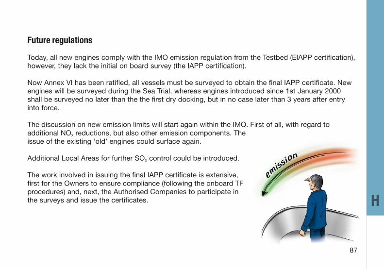
Future regulations
Today, all new engines comply with the IMO emission regulation from the Testbed (EIAPP certification),however, they lack the initial on board survey (the IAPP certification).
Now Annex VI has been ratified, all vessels must be surveyed to obtain the final IAPP certificate. Newengines will be surveyed during the Sea Trial, whereas engines introduced since 1st January 2000shall be surveyed no later than the the first dry docking, but in no case later than 3 years after entryinto force.
The discussion on new emission limits will start again within the IMO. First of all, with regard toadditional NOx reductions, but also other emission components. Theissue of the existing ‘old’ engines could surface again.
Additional Local Areas for further SOx control could be introduced.
The work involved in issuing the final IAPP certificate is extensive,first for the Owners to ensure compliance (following the onboard TFprocedures) and, next, the Authorised Companies to participate inthe surveys and issue the certificates.

88
Owners might want to introduce ‘new type’ spare parts (e.g. the Slide Fuel Valve) to improve engineconditions. Accordingly, MAN B&W Diesel will prepare amendments for such cases.
Further requirements for additional emission reductions, as used on some stationary power plants, arepossible, but will unavoidably lead to increased first cost or/and operational costs. For many years,MAN B&W Diesel has been working on different aspects of emission reductions (see MAN B&W Dieselpaper, P.333-97-04; ‘How to deal with Emission Control’).
The next level of emission limits have already been proposed by the leading environmentally-activecountries and associations (the US, Japan and EU). A further NOx reduction of some 25% to 30% and,eventually, include other emission components like CO, HC and soot.
The new ME engine concept offers a high level of flexibility to optimise the engine for differentemission regulations in Local Areas without penalising the fuel consumption or other emissioncomponents elsewhere.
89
I
I. Assistance from MAN B&W Diesel
Department 2110 (Classifications) can inform you about the procedures for the TF.
Department 4100 (Diesel Service) offers the following services:
• Review and assistance to Owners to ensure on board compliance (engines with ‘IMOcertificates’ before and after the Annex enters into force)
• Guiding emission measurements (for other purposes than IMO certification/amendments).
Departments 4220/30/40 ensure delivery of genuine spare parts complying with theIMO regulations.
Department 2431 (Basic Research and Emissions) can, in special cases,perform IMO-compliant emission measurements on board.

90
Survey Start
SurveyType
Testbed: Inspection ofPre-Technical File (EIAPP)
EngineType
Performance Check:a) measure performanceb) measure NO
c) check fuel nozzle andECS version
d) other NO componentse) verify settings
x
x
NO components Check:x
Performance andComponent approval
1. Parent Engine2. Member Engine
Performance Check:a) measure performanceb) verify performance
c) check fuel nozzle and ECS versiond) other NO componentse) verify settings
Print out survey code tables(with EIAPP application)
NO components Checkx
x
Performance andComponent approval
Sign Documents
AdjustAdjust
YesYes
No No
J. Overview of Survey Routines

91 J
NO components Checkx
c) check fuel nozzle and ECS versiond) other NO components
(as considered necessary)e) verify settings
(as considered necessary)
Print out survey tables
x
Performance Check:a) measure performanceb) verify performance (VIT or non-VIT)
c) check fuel nozzle and ECS versiond) other NO components
(as considered necessarye) verify settings
(as considered necessary)
Print out survey tables
NO components Checkx
x
Inspection of:Technical File and Record Book
Inspection of:Technical File (IAPP)
Adjustment orComponent Changes
Survey Finish Sign Documents and add to Record Book
Adjust
Performance andComponent approval
No Yes
YesNo
4. On-board Survey3. Sea Trial

92
Notes:

93
Notes:

94
Notes:

95
Notes:

96
Notes: