
A Guidance Document for the Santa Ana Region of Riverside ... · WATER QUALITY MANAGEMENT PLAN . A...
94
WATER QUALITY MANAGEMENT PLAN A Guidance Document for the Santa Ana Region of Riverside County Date approved by the Santa Ana Regional Water Quality Control Board: October 22, 2012
Transcript of A Guidance Document for the Santa Ana Region of Riverside ... · WATER QUALITY MANAGEMENT PLAN . A...

WATER QUALITY MANAGEMENT PLAN A Guidance Document for the Santa Ana Region of Riverside County
Date approved by the Santa Ana Regional Water Quality Control Board: October 22, 2012
Water Quality Management Plan
for the Santa Ana Region of Riverside County
In compliance with Order No. R8-2010-0033, this WQMP is implemented by the following Co-Permittees in the Santa Ana Region.
Co-Permittees:
County of Riverside All Project applications: www.countyofriverside.us/ For WQMP questions in unincorporated County areas: www.rcflood.org Beaumont www.ci.beaumont.ca.us/ Calimesa www.cityofcalimesa.net/
Canyon Lake www.cityofcanyonlake.com Corona www.discovercorona.com Eastvale www.eastvalecity.org/ Hemet www.cityofhemet.org/
Jurupa Valley www.jurupavalley.org/ Lake Elsinore www.lake-elsinore.org/ Menifee www.cityofmenifee.us/ Moreno Valley www.moval.org/
Norco www.norco.ca.us/ Perris www.cityofperris.org/ Riverside www.riversideca.gov/ San Jacinto www.ci.san-jacinto.ca.us/
Prepared with assistance from Brown and Caldwell
Dan Cloak Environmental Consulting

W A T E R Q U A L I T Y M A N A G M E M E N T P L A N F O R T H E S A N T A A N A R E G I O N O F R I V E R S I D E C O U N T Y
ii
Table of Contents 1.0 POLICIES AND PROCEDURES .............................................................................................................................. 4
1.1. Projects Requiring a WQMP .......................................................................................................................... 4 1.2. Requirements for Public Works Projects ....................................................................................................... 6 1.3. Compliance Process at a Glance .................................................................................................................... 8 1.4. WQMP Requirements for Projects in Progress ........................................................................................... 10 1.5. WQMP Requirements for Phased Projects ................................................................................................. 12 1.6. Types of Project-Specific WQMPs ............................................................................................................... 12
2.0 CONCEPTS AND CRITERIA ................................................................................................................................ 14 2.1. Water-Quality Regulations and Concepts ................................................................................................... 14 2.2. Potential Impacts of Development ............................................................................................................. 17 2.3. Hydrology for NPDES Compliance ............................................................................................................... 20 2.4. Low Impact Development ........................................................................................................................... 25 2.5. Selection of Permanent Source Control BMPs ............................................................................................ 42
3.0 PREPARING YOUR PROJECT-SPECIFIC WQMP................................................................................................... 43 3.1. Assemble Project and Site Information ....................................................................................................... 44 3.2. Optimize Size Utilization ............................................................................................................................. 45 3.3. Delineate Drainage Management Areas ..................................................................................................... 48 3.4. Implement LID BMPs ................................................................................................................................... 53 3.5. Alternative Compliance ............................................................................................................................... 63 3.6. Hydromodification ...................................................................................................................................... 68 3.7. Specify Source Control BMPs ...................................................................................................................... 70 3.8. Coordination of WQMP Design ................................................................................................................... 70 3.9. Develop an O&M Plan ................................................................................................................................. 70
4.0 COORDINATION WITH OTHER SITE PLANS ....................................................................................................... 72 4.1. Coordination with Site, Architectural, and Landscaping Plans .................................................................... 72 4.2. Certification ................................................................................................................................................. 73 4.3. Construction Plan WQMP checklist ............................................................................................................. 73 4.4. Prepare an Operations and Maintenance Plan ........................................................................................... 74 4.5. Structural BMP Construction....................................................................................................................... 74
5.0 OPERATION & MAINTENANCE OF STORMWATER BMPS .................................................................................. 77 5.1. Stage 1: Ownership and Maintenance Responsibility ................................................................................. 79 5.2. Stage 2: General Maintenance Requirements ............................................................................................ 80 5.3. Stage 3: Stormwater BMP O&M Plan .......................................................................................................... 81 5.4. Stage 4: Prepare Customized Maintenance Plans ....................................................................................... 83 5.5. Stage 5: Interim Operation & Maintenance ................................................................................................ 87 5.6. Stage 6: Transfer Responsibility .................................................................................................................. 87 5.7. Stage 7: Operation & Maintenance Verification ......................................................................................... 87

W A T E R Q U A L I T Y M A N A G M E M E N T P L A N F O R T H E S A N T A A N A R E G I O N O F R I V E R S I D E C O U N T Y
iii
EXHIBIT A: Isohyetal Map for the 85th Percentile 24-hour Storm Event
EXHIBIT B: Project-Specific WQMP Template
EXHIBIT C: LID BMP Design Handbook
EXHIBIT D: Transportation Project Guidance
EXHIBIT E: WQMP Applicability Checklist
EXHIBIT F: WQMP Review Checklist
EXHIBIT G: Model Construction Checklist
EXHIBIT H: Glossary

W A T E R Q U A L I T Y M A N A G M E M E N T P L A N F O R T H E S A N T A A N A R E G I O N O F R I V E R S I D E C O U N T Y
iv
Figures
FIGURE 1-1 DEVELOPMENT PROCESSS FLOW CHART ................................................................................. 10
FIGURE 3-1 SELF-TREATING AREAS ............................................................................................................. 48
FIGURE 3-2 SELF-RETAINING AREAS ............................................................................................................ 49
FIGURE 3-3 RELATIONSHIP OF IMPERVIOUS TO PERVIOUS ........................................................................ 51
FIGURE 3-4 MORE THAN ONE DRAINAGE MANAGEMENT AREA ................................................................ 52
FIGURE 3-5 ONE DRAINAGE MANAGEMENT AREA ..................................................................................... 52
FIGURE 3-6 LID BMP FEASIBILITY FLOW CHART .......................................................................................... 57
FIGURE 3-7 HYDROMODIFICATION CRITERIA FOR THE SANTA ANA REGION ............................................. 68
Tables
TABLE 1-1 PRIORITY DEVELOPMENT CATEGORIES ..................................................................................... 5
TABLE 2-1 IMPERVIOUS FRACTION BASED ON DIFFERENT LAND USE COVERS ........................................ 35
TABLE 2-2 HARVEST AND USE DATA FOR TOILET USE ............................................................................... 36
TABLE 2-3 HARVEST AND USE DATA FOR IRRIGATION USE ...................................................................... 37
TABLE 2-4 HARVEST AND USE DATE FOR OTHER NON-POTABLE USES .................................................... 40
TABLE 2-5 RECOMMENDED EFFECTIVE AREA REQUIRED TO BE MADE AVAILABLE FOR LID BMPS ........................................................................................................................................ 40
TABLE 3-1 FORMAT FOR TABULATING SELF-TREATING AREAS ................................................................. 48
TABLE 3-2 FORMAT FOR TABULATING SELF-RETAINING AREAS ............................................................... 49
TABLE 3-3 RUNOFF FACTORS FOR DRAINING PARTIALLY PERVIOUS AREAS INTO SELF-RETAINING AREAS .................................................................................................................... 50
TABLE 3-4 FORMAT FOR TABULATING AREAS DRAINING TO SELF-RETAINING AREAS. ............................ 51
TABLE 3-5 LID BMP APPLICABILITY ............................................................................................................ 58
TABLE 3-6 FORMAT FOR PRESENTING CALCULATIONS FOR LID BMPS BASED ON AN AREA SIZING FACTOR ......................................................................................................................... 60
TABLE 3-7 FORMAT FOR PRESENTING CALCULATIONS FOR LID BMPS BASED ON AN AVAILABLE DESIGN SHEET ........................................................................................................ 60
TABLE 3-8 WATER QUALITY CREDITS FOR APPLICABLE PROJECT CATEGORIES ........................................ 64
TABLE 3-9 POTENTIAL POLLUTANTS GENERATED BY LAND USE TYPE ..................................................... 65
TABLE 3-10 FORMAT FOR PRESENTING CALCULATIONS FOR TREATMENT CONTROL BMPS .................... 66
TABLE 3-11 FORMAT FOR TABLE OF PERMANENT AND OPERATIONAL SOURCE CONTROL MEASURES ............................................................................................................................... 69
TABLE 4-1 FORMAT FOR CONSTRUCTION PLAN WQMP CHECKLIST ......................................................... 74
TABLE 5-1 SCHEDULE FOR PLANNING OPERATION AND MAINTENANCE ................................................. 80

W A T E R Q U A L I T Y M A N A G E M E N T P L A N F O R T H E S A N T A A N A R E G I O N O F R I V E R S I D E C O U N T Y
1
INTRODUCTION Read Chapters 1 and 2 to get a general understanding of the requirements. Then follow the step-by-step instructions in Chapter 3 to prepare your Project-Specific Water Quality Management Plan.
This Water Quality Management Plan (WQMP) is a guidance document that will help you to design your project in compliance with Santa Ana Regional Water Quality Control Board (Santa Ana Regional Board) requirements for Priority Development Projects. These requirements are specified in the National Pollutant Discharge Elimination System (NPDES) Municipal Separate Storm Sewer System (MS4) permit issued to the Riverside County Flood Control and Water Conservation District, County of Riverside, and
other Cities within the Santa Ana River watershed in the 2010 MS4 Permit. The area covered by this MS4 Permit is referred to as the Santa Ana Region (SAR). The requirements are complex and technical. Because every project is different, you should begin, if possible, by scheduling a pre-application meeting with the applicable Co-Permittee staff.
Be sure to use the most recent version of the WQMP, including updates and errata. The most recent version is at www.rcflood.org/NPDES/Developers.aspx. This WQMP may be updated periodically based on the Co-Permittees’ experience with implementation of this document. Any non-substantive updates to the WQMP will be provided in the Co-Permittees’ Annual Report to the Santa Ana Regional Board. Substantive updates will be submitted to Santa Ana Regional Board staff for review and approval prior to implementation. If you are reading the WQMP on a computer, you can use hyperlinks within this document to navigate from section to section, and if you have an internet connection, you can directly access various internet references. The hyperlinks are throughout the text, as well as in “References and Resources” sections (marked by the icon) and in the Bibliography.
To use the WQMP, start by reviewing Chapter 1 to find out whether and how the requirements apply to your project. Chapter 1 also provides an overview of the entire process of planning, design, construction, operation and maintenance leading to compliance.
Start
I C O N K E Y
Helpful Tip
Submittal Requirement
Terms to Look Up
References & Resources

W A T E R Q U A L I T Y M A N A G M E M E N T P L A N F O R T H E S A N T A A N A R E G I O N O F R I V E R S I D E C O U N T Y
2
Construction-Phase Controls
Your Project-Specific WQMP is a separate document from the
Stormwater Pollution Prevention Plan (SWPPP). A SWPPP provides
for temporary measures to control discharges of sediment and other pollutants during construction at
sites that disturb one acre or more, whereas a WQMP is
required to address discharges from the post-construction
use of the site.
If there are terms and issues you find puzzling, look for answers in the Glossary or in Chapter 2. Chapter 2 provides background on key stormwater concepts and water quality regulations, including criteria for the design and selection of Stormwater Best Management Practices (BMPs).
Then proceed to Chapter 3 and follow the step-by-step guidance to prepare a Project-Specific WQMP for your site. A preliminary WQMP is commonly required to be submitted with your application for entitlements and development approvals and must be approved by the Co-Permittee before any approvals or entitlements will be granted. A final Project-Specific WQMP will be required to be submitted and approved prior to issuance of permits.
As you proceed with design and construction of your project, consult Chapter 4 for guidance on preparing construction documents and overseeing construction of Stormwater BMPs.
In Chapter 5 you’ll find a detailed description of the process for ensuring operation and maintenance of your Stormwater BMPs over the life of the project. The chapter includes step-by-step instructions for preparing a Stormwater BMP Operation and Maintenance Plan.
Throughout each chapter, you’ll find references and resources to help you understand the regulations, complete the WQMP, and design the project to be protective of water quality to the Maximum Extent Practicable (MEP).
PLAN AHEAD TO AVOID THE THREE MOST COMMON MISTAKES
The most common (and costly) errors made by applicants for development approvals with respect to stormwater compliance are:
Not planning for compliance early enough. You should think about the strategy for compliance with WQMP requirements before completing a conceptual site design or sketching a layout of subdivision lots (Chapter 3). It is highly recommended that the project team (civil engineers, planners, architects, landscape architects, etc.) meet and confer at project inception to discuss design strategies that meet the requirements herein.
Assuming proprietary Stormwater BMPs (Treatment Control BMPs) will be adequate for compliance. LID BMPs that maximize infiltration, harvest and use, evapotranspiration and/or bio-treatment, are now required for nearly all projects. See Chapter 2 for criteria affecting what Stormwater BMPs can be used on a project.

W A T E R Q U A L I T Y M A N A G M E M E N T P L A N F O R T H E S A N T A A N A R E G I O N O F R I V E R S I D E C O U N T Y
3
Not planning for long-term maintenance of Stormwater BMPs, and inspections / verifications by the Co-Permittee. Consider who will own and who will maintain the BMPs in perpetuity and how they will obtain access, and identify which arrangements are acceptable to the Co-Permittee (Chapter 5).

W A T E R Q U A L I T Y M A N A G E M E N T P L A N F O R T H E S A N T A A N A R E G I O N O F R I V E R S I D E C O U N T Y
4
1.0 POLICIES AND PROCEDURES
Determine if your project requires a Project-Specific WQMP, and review the steps to compliance.
1.1. PROJECTS REQUIRING A WQMP
Before continuing to use this document, it is highly encouraged that you use the ‘Locate your Watershed’ tool available at www.rcflood.org/npdes to verify that your project is within the Santa Ana Region.
1.1.1. Priority Development Projects
The 2010 SAR MS4 Permit (see Chapter 2) requires that a WQMP be prepared for all projects within the SAR that meet the “Priority Development Project” categories and thresholds listed in Table 1-1 and for which a final map or permit for discretionary approval is sought. Additionally, the WQMP Applicability Checklist provided in Exhibit E can be used as a means to document a conclusion that a project is, or is not, subject to the WQMP requirements, which includes “Other Development Projects” (as defined in the Glossary as those that are not “Priority Development Projects”). Note some thresholds are defined by square footage of impervious area; others by land area of development; others by area disturbed. For Permittee projects, see the “Requirements for Public Works Projects” section later in this chapter.
If your project is classified as an “Other Development Project,” a Project-Specific WQMP is generally not required. However, “Other Development Projects” are required to incorporate appropriate LID Principles (Site Design), Source Control, and other BMPs which may or may not include Treatment Control BMPs. Co-Permittee staff will require Project-Specific WQMPs for these Other Development Projects not within the categories in Table 1-1, if deemed necessary to ensure that the potential for significant adverse water quality impacts to stormwater are mitigated.
Chapter
1
I C O N K E Y
Helpful Tip
Submittal Requirement
Terms to Look Up
References & Resources

C H A P T E R 1 : P O L I C I E S A N D P R O C E D U R E S
5
When determining whether WQMP requirements apply, a “project” should be defined consistent with the California Environmental Quality Act (CEQA) definition of “project.” That is, the “project” is the whole of an action which has the potential for adding or replacing or resulting in the addition or replacement of roofs, pavement, or other impervious surfaces. “Whole of an action” means the project may not be segmented or piecemealed into small parts if the effect is to reduce the quantity of impervious area for any part to below the applicable threshold.
Each Co-Permittee shall ensure that an appropriate WQMP is prepared for the categories listed in Table 1-1 for which a map or permit for discretionary approval is sought.
TABLE 1-1. Priority Development Categories
Category Threshold Notes
New Development Projects 10,000 SF New developments that create 10,000 square feet or more of impervious surface (collectively over the entire project site) including commercial and industrial projects and residential housing subdivisions requiring a Final Map (i.e., detached single family home subdivisions, multi-family attached subdivisions, condominiums, apartments, etc.); mixed use and public projects (excluding Permittee road projects). This category includes development projects on public and private land, which fall under the planning and building authority of the Co-Permittees.
Automotive Repair Shops SIC CODE Automotive repair shops (with SIC codes 5013, 5014, 5541, 7532-7534, 7536-7539).
Restaurants 5,000 SF Restaurants (with SIC code 5812) where the land area of development is 5,000 square feet or more.
Hillside Developments 5,000 SF Hillside developments disturbing 5,000 square feet or more which are located on areas with known erosive soil conditions or where the natural slope is twenty-five percent or more.
Developments adjacent to, or that discharge directly into Environmentally Sensitive Areas
2,500 SF Developments of 2,500 square feet of impervious surface or more adjacent to (within 200 feet) or discharging directly into ESAs.
Parking Lots 5,000 SF Parking lots of 5,000 square feet or more exposed to stormwater. Parking lot is defined as land area or facility for the temporary parking or storage of motor vehicles.
Retail Gasoline Outlets (RGOs) 5,000 SF Retail Gasoline Outlets (RGOs) that are 5,000 square feet or more with a projected average daily traffic of 100 or more vehicles per day.
Significant Redevelopment Projects
5,000 SF The addition or replacement of 5,000 square feet of impervious surface on an already developed site. See Section 1.1.2 below for applicability of the “50% Rule”.
C H A P T E R 1 : P O L I C I E S A N D P R O C E D U R E S
6
Priority Development Projects are defined as all new Development Projects that fall under the project categories or locations listed in Table 1-1 and for which a final map or permit for discretionary approval is sought. Regarding Priority Development Project Categories listed in Table 1-1, where a new Development Project feature, such as a parking lot, falls into a Priority Development Project Category, the entire project footprint is subject to WQMP requirements. These requirements may be excluded if the WQMP requirement causes a delay that compromises public safety, public health, and/or environmental protection.
1.1.2. The “50% Rule” for Redevelopment Projects
Projects that will expand or modify a previously developed site may be required to retrofit the existing site for compliance with this WQMP (including runoff from existing areas not otherwise being modified as part of the current project).
If the proposed project results in an increase of, or replacement of, 50 percent or more of the impervious surface of an existing developed site, then the entire existing developed site must be addressed through the WQMP design.
Where the project will result in an increase of less than 50 percent of the existing impervious surface area, and the existing development was not subject to WQMP requirements, the treatment requirement applies only to the addition or replacement impervious area, and not to the entire developed site.
These requirements do not include routine maintenance activities that are conducted to maintain original line and grade, hydraulic capacity, original purpose of the facility, or emergency redevelopment activity required to protect public health and safety.
Co-Permittee staff will determine case-by-case when and how the “50% Rule” applies. Note that when determining whether the 50% Rule applies to a project, impervious areas that are removed and replaced are counted (that is, no credit is given for removal of existing impervious square footage). Requirements to mitigate a hydrologic condition of concern (HCOC) use the developed condition of a previously developed site as a baseline. Removal of existing impervious square footage may be credited when determining whether runoff rates or durations will increase.
1.2. REQUIREMENTS FOR PUBLIC WORKS PROJECTS
Public Works / Capital Improvement projects are considered Priority Development Projects, requiring a WQMP, if they meet the criteria in Sections 1.1.1 and/or 1.1.2, except as provided below.

C H A P T E R 1 : P O L I C I E S A N D P R O C E D U R E S
7
1.2.1. Co-Permittee Transportation Projects
In accordance with Finding II.G.18 in the MS4 Permit, a Project-Specific WQMP is not required for Co-Permittee street road and highway capital projects. Instead, as described in Permit Provision XII.F.1, the Co-Permittees are required to develop and implement ‘standardized design and post-construction BMP guidance to reduce the discharge of Pollutants from such projects to the MEP. This guidance, referred to as ‘Low Impact Development: Guidance and Standards for Transportation Projects for Santa Ana Area’ is included as Exhibit D to this WQMP. Roadway projects that implement the Transportation Project Guidance (TPG) will not be required to prepare a Project-Specific WQMP.
Refer to Exhibit D to determine if the proposed project is indeed a ‘Transportation Project’. If it is, follow the instructions in Exhibit D for designing and documenting the deployment of LID Principles and Stormwater BMPs on the project. If it is not a ‘Transportation Project’, follow the guidance for “Other Public Projects” below.
1.2.2. Watershed Protection Projects
Watershed Protection Projects, in the context of stormwater management, are constructed to prevent economic, social, and environmental damage to the watershed, including receiving waters, by providing the following:
Water quality protection by the proper management of stormwater and floodplains
Flood risk reduction to adjacent land uses, stored matter, and stockpiled material
Elimination of the comingling of stormwater and hazardous materials
Erosion Mitigation
Restoration of Rivers and Ecosystems
Groundwater Recharge
Creation of new open space and wetlands
Programs for water conservation, stormwater capture and management
Retrofit projects constructed to improve water quality
Watershed Protection Projects provide an important environmental benefit toward protecting Beneficial Uses by preventing stormwater from mobilizing pollutant loads and/or managing pollutant sources into receiving waters from adjacent land uses.

C H A P T E R 1 : P O L I C I E S A N D P R O C E D U R E S
8
Any potential impacts upon the environment from Watershed Protection Projects are mitigated through required compliance with CEQA, the United States Army Corps of Engineers 404 Permits, RWQCB Section 401 Water Quality Certification and California Department of Fish and Game Section 1602 Streambed Alteration Agreements. Furthermore, Watershed Protection Projects are not considered development projects as they do not involve any post-construction human use or activity, and have no associated Pollutants of Concern. Consequently, these projects would not require the preparation of a Project-Specific WQMP. However, such projects may be considered “Other Development Projects”. “Other Development Projects” are required to incorporate appropriate LID Principles (Site Design), Source Control, and other BMPs which may or may not include Treatment Control BMPs. Permittee staff will require Project-Specific WQMPs for these Other Development Projects not within the categories in Table 1-1, if deemed necessary to ensure that the potential for significant adverse water quality impacts to stormwater are mitigated.
1.2.3. Utility Projects
Utility Projects consist of essential infrastructure that may provide stormwater conveyance, raw sewage management, potable water, gas, oil, telecommunications and other services. Securing and protecting these important utilities below ground and out of the elements significantly decreases the risk of damage and prevents the services from contaminating the watershed. Installation of a utility may involve the replacement of impervious surfaces, however, they are typically replaced to existing line and grade. The project itself does not involve any post-construction human use or activity, neither adds/nor modifies any Pollutants of Concern, and as such would not be required to prepare a Project-Specific WQMP. However, such projects may be considered ‘Other Development Projects’, subject to the minimum LID and Source control requirements identified in the Permittee’s LIP. If the projects create new impervious surface, the new impervious surface would be subject to WQMP triggers or Road Standards Guidance triggers as appropriate.
1.2.4. Other Public Projects
Public Works projects, other than Transportation Projects discussed above, that are implemented by a Co-Permittee are required to prepare a Project-Specific WQMP if the project is similar in nature to the Priority Development Projects described in Table 1-1, and if the project meets the thresholds described therein.
1.3. COMPLIANCE PROCESS AT A GLANCE
For Development Project approval, applicants should follow these general steps to comply with the requirements of the 2010 SAR MS4 Permit:
1. Discuss WQMP requirements during a pre-application meeting with Co-Permittee staff, if possible. This can help you to confirm any requirements specific to the local

C H A P T E R 1 : P O L I C I E S A N D P R O C E D U R E S
9
Co-Permittee for your application process. Note that the Co-Permittee will require the applicant to certify that the project does or does not qualify as a Priority Development Project. The Co-Permittee will nevertheless have the ultimate discretion as to whether a WQMP is required for any particular project.
2. If your project is subject to this Santa Ana Region WQMP, review the instructions in this WQMP BEFORE you prepare your tentative map, preliminary site plan, drainage plan, and landscaping plan. The requirements in this WQMP will affect each of these items. Neglecting to appropriately consider and address the requirements of this WQMP at all stages of project planning and design, will likely result in costly re-design being required.
3. When required by the Co-Permittee, prepare a preliminary Project-Specific WQMP and submit it with your application for Discretionary Approvals (entitlements).
4. Following any Discretionary Approval, initiate your final Project-Specific WQMP as part of your plan to complete your detailed project design, incorporating the LID Principles and Stormwater BMPs committed to in your preliminary Project-Specific WQMP.
5. In a table on your grading or improvement plans, list each Structural Post-Construction and Source Control BMP, and the plan sheet where it appears.
6. Prepare the final Project-Specific WQMP, incorporating a draft Stormwater BMP Facility Operation and Maintenance Plan and submit it with your application for grading plans, improvement plans, and building permits. Execute legal documents assigning responsibility for operation and maintenance of Stormwater BMPs. All Co-Permittees require that legal agreements and financial commitments for operation and maintenance be recorded prior to recordation of a final map or parcel or Certificate of Occupancy if a map is not required.
7. Protect proposed Post-Construction BMPs (and underlying soils) during construction, and maintain them following construction.
8. Following construction, submit a final Stormwater BMP Facility Operation and Maintenance Plan and formally transfer responsibility for maintenance to the owner or permanent occupant. Typically, the Co-Permittees will require the final Stormwater BMP Facility Operation and Maintenance Plan prior to issuance of Certificate of Occupancy.
9. Following occupancy, the occupant or owner must maintain records that all necessary maintenance of Post-Construction BMP facilities has been performed and
Local Requirements Individual Co-Permittees may have requirements that differ from, or are in addition to, this WQMP. See Co-Permittee for
local requirements.

C H A P T E R 1 : P O L I C I E S A N D P R O C E D U R E S
10
allow periodic Co-Permittee inspections of Stormwater BMPs. Where Co-Permittees allow or require self-certifications of Stormwater BMPs, the occupant or owner must certify that the Stormwater BMPs are properly maintained and submit reports, prepared and certified by a Professional Engineer, to the Co-Permittee staff upon their request.
Preparation of a complete and detailed Project-Specific WQMP is the key to cost-effective compliance and expeditious review of your project. Instructions for preparing a Project-Specific WQMP are in Chapter 3.
General PlanEnvironmental
Review andDocumentation
Initial Study / CEQA Checklist
Review of General Plan Elements
Development ProjectReview, Approval, and Permitting
Environmental Documentation• Negative Declaration• Mitigated Negative Declaration• Environmental Impact Report
(A preliminary WQMP may be included at this stage.)
Amendment(if necessary)
OtherDevelopment
Projects Subject to
Provisions of the LIP
MitigationMonitoring
Reporting Plan
Priority Project & Significant Redevelopment Projects
Conditions of Approval(A preliminary WQMP may be included for Tentative Tract, Parcel, or Subdivision Map
approval.)
WQMPs/SUSMPsFinal
Project-Specific WQMP
Building or Grading Permits
Tracking,Inspection,
& Enforcement
Conditions of Approval and/or
Permit Conditions
FIGURE 1-1: Development Process Flow Chart
1.4. WQMP REQUIREMENTS FOR PROJECTS IN PROGRESS
Requirements for preparing Project-Specific WQMPs have been in place for all applicable projects submitted to the Co-Permittee after December 31, 2004. The 2010 SAR MS4 Permit however includes new/additional requirements for WQMPs that are reflected in this revised WQMP Guidance Document. The following describes how these new requirements will be

C H A P T E R 1 : P O L I C I E S A N D P R O C E D U R E S
11
applied to category projects that have already begun the process of securing approvals from the Co-Permittee.
Approved Projects
Approved Projects are those Development Projects that have a Co-Permittee-approved preliminary Project-Specific WQMP and have received discretionary approvals from the Advisory Agency as defined in the California Subdivision Map Act or local ordinance. These Approved Projects have been issued Conditions of Approval for land use entitlements consisting of land divisions (tract and parcel maps), conditional use permits, and surface mining permits or similar land-use entitlements. Approved Projects meeting the criteria below may pursue grading, building or occupancy permits without triggering the New Development/Significant Redevelopment requirements of this revised WQMP.
Approved Projects are not exempt from the New Development/Significant Redevelopment requirements of this revised WQMP if they are filing for a new revision, modification or change of their land use entitlement(s) for which Conditions of Approval have been previously issued and whose approval is considered discretionary (excluding grading, building, and occupancy permits).
If you believe your project may be grandfathered, check with the Co-Permittee to verify applicable requirements. Each Co-Permittee individually determines how and when projects will be allowed to be grandfathered pursuant to each Co-Permittee’s LIP. To summarize, for all projects which a map or permit for discretionary approval is sought the following minimum requirements apply:
• Consistent with MS4 Permit section XII.L, projects approved prior to 45 days from the date of Regional Board approval of this revised WQMP will continue to comply with the WQMP dated January 22, 2009
• Consistent with MS4 Permit section XII.L, project approvals beginning 45 days from the date of Regional Board approval of this revised WQMP, Project-Specific WQMPs will be required to meet the new LID and HCOC requirements herein to the MEP
• As described in XII.E.1, beginning six months after the date of Regional Board approval of this revised WQMP, all projects that meet the criteria of Table 1-1 that are not Approved Projects, will be required to prepare a Project-Specific WQMP that fully meets the requirements of this revised WQMP Guidance Document

C H A P T E R 1 : P O L I C I E S A N D P R O C E D U R E S
12
1.5. WQMP REQUIREMENTS FOR PHASED PROJECTS
Co-Permittee staff may require, as part of an application for approval of a phased Development Project, a preliminary Project-Specific WQMP. As discussed below, this report describes and illustrates, in broad outline, how the drainage for the entire project will comply with the WQMP requirements. The level of detail in the preliminary WQMP shall be consistent with the scope and level of detail of the development approval being considered. A more detailed final Project-Specific WQMP for the entire project, or multiple final project specific WQMPs for individual phases of the entire project, will be submitted with applications for subsequent recordation, grading or building permits as appropriate. The obligation to install Stormwater BMPs for the entire project is met if BMPs are constructed with the requisite capacity to serve the entire project, even if certain phases of the project may not have BMP capacity located within that phase. Stormwater BMPs with sufficient capacity to serve the phase(s) addressed by the final WQMP must be functional prior to issuance of occupancy permits, or certificates of use (or equivalent), even if those Stormwater BMPs are located in a later (or future) phase of the project.
1.6. TYPES OF PROJECT-SPECIFIC WQMPS
1.6.1. Preliminary Project-Specific WQMP requirements
If a Discretionary Approval would entitle construction of new or replaced improvements which, individually or in aggregate, would exceed the thresholds in Table 1-1, then the applicant must prepare a preliminary Project-Specific WQMP. The level of detail in a preliminary Project-Specific WQMP will depend upon the level of detail known about the overall project design at the time project approval is sought.
For example, if approval of a tentative tract map application would entitle site improvements that individually or in aggregate would exceed the thresholds for Priority Development Projects in Table 1-1, the applicant should prepare a preliminary Project-Specific WQMP. If particular plans for individual lots have not been identified, the preliminary Project-Specific WQMP should nevertheless identify the type, size, location, and final ownership of Stormwater BMPs
adequate to serve new roadways and any common areas, and to also manage runoff from an expected reasonable estimate of the square footage of future roofs, driveways, and other impervious surfaces on each individual lot. The Co-Permittee will then condition approval of the map on implementation of a final Project-Specific WQMP that is in substantial conformance with the approved preliminary Project-Specific WQMP prior to issuance of grading / building permits.
Local Requirements
Individual Co-Permittees may have requirements that differ
from, or are in addition to, this WQMP. Check with the applicable
Co-Permittee.

C H A P T E R 1 : P O L I C I E S A N D P R O C E D U R E S
13
If a Co-Permittee deems it necessary, the future improvements on one or more lots may be limited by a deed restriction or dedication of an appropriate easement, to suitably restrict the future building of structures at each stormwater facility location.
In general, it is recommended Stormwater BMPs not be located on individual single-family residential lots, particularly when those BMPs manage runoff from streets, or from common areas. However, local requirements vary. Most often, it is better to locate Stormwater BMPs on one or more separate, jointly owned parcels.
If a subdivision map being proposed is purely to subdivide land, and the Discretionary Approval does not entitle particular improvements to be made on the subdivided parcels that, in aggregate, would exceed the thresholds in Table 1-1, a WQMP may not be required, at the discretion of the Co-Permittee. For example, if a 30-acre parcel zoned for rural residential is to be subdivided into two 15-acre rural residential parcels, and any known or proposed improvements on either 15-acre parcel would not be classified as a Priority Development Project per Table 1-1, then, at the discretion of the Co-Permittee, a preliminary Project-Specific WQMP may not be required at the time of the Discretionary Approval of the subdivision map. As the subdivision map did not create entitlements for specific improvements that exceed the thresholds in Table 1-1, subsequent proposals for improvements on either or both of the parcels will be subject to Discretionary Approvals, and conditions for preparation of a Project-Specific WQMP as applicable.
1.6.2. Final Project-Specific WQMP requirements
A final Project-Specific WQMP shall be submitted and approved by the Co-Permittee for all Priority Development Projects prior to the issuance of any building or grading permits. The final Project-Specific WQMP shall be in substantial conformance with any preliminary WQMP submitted and approved by the Co-Permittee during the land use entitlement process.

W A T E R Q U A L I T Y M A N A G E M E N T P L A N F O R T H E S A N T A A N A R E G I O N O F R I V E R S I D E C O U N T Y
14
2.0 CONCEPTS AND CRITERIA
Technical background and explanations of policies and design requirements.
The 2010 SAR MS4 Permit mandates that the Co-Permittees develop and implement a comprehensive program to prevent stormwater Pollution. That program now includes measures to prevent Pollution from municipal facilities and operations, identification and elimination of Illicit Discharges to the MS4, business inspections, public outreach, construction site inspections, monitoring and studies of stream health,
and control of runoff Pollutants from Priority Development Projects, as well as implementation of programs aimed at specific Pollutants (nutrients and pathogens) in some sub-watersheds.
The 2010 SAR MS4 Permit mandates a LID approach to stormwater treatment and management of runoff discharges for Priority Development Projects. This chapter explains the technical background of the Co-Permittees’ approach to implementing the LID requirements.
2.1. WATER-QUALITY REGULATIONS AND CONCEPTS
The 2010 SAR MS4 Permit requires the Co-Permittees to condition Priority Development Projects with incorporation of specified stormwater controls. The Co-Permittees’ Annual Reports to the Santa Ana Regional Board includes a list of BMPs approved, constructed, and/or operating during the year.
Chapter
2
I C O N K E Y
Helpful Tip
Submittal Requirement
Terms to Look Up
References & Resources

C H A P T E R 2 : C O N C E P T S A N D C R I T E R I A
15
The 2010 SAR MS4 Permit requires that applicable Priority Development Projects:
• Design the site to minimize imperviousness, detain runoff, and infiltrate, reuse or evapotranspire runoff where feasible.
• Cover or control sources of stormwater Pollutants.
• Use LID to infiltrate, evapotranspire, harvest and use, or treat runoff from impervious surfaces.
• Ensure runoff does not create a Hydrologic Condition of Concern (HCOC).
• Maintain Stormwater BMPs.
2.1.1. Maximum Extent Practicable
Clean Water Act Section 402(p)(3)(iii) sets the standard for control of stormwater pollutants as “maximum extent practicable” (MEP), but doesn’t define that term. As implemented, “maximum extent practicable” is ever-changing and varies with conditions. In general, to achieve the MEP standard, Co-Permittees must require deployment of whatever BMPs are technically feasible (that is, are likely to be effective) and are not cost prohibitive.*
Many stormwater controls, including LID, have proven to be practicable in most Development Projects. To achieve fair and effective implementation, criteria and guidance for those controls must be detailed and specific—while also offering the right amount of flexibility or exceptions for special cases. The 2010 SAR MS4 Permit includes various standards, including hydrologic criteria, which the Santa Ana Regional Board has found to provide “MEP” control.
2.1.2. Best Management Practices
Clean Water Act Section 402(p) and USEPA regulations (40 CFR 122.26) specify a municipal program of “management practices” to control stormwater Pollutants. BMP refers to any kind of procedure or device designed to minimize the quantity of pollutants that enter the MS4.
2.1.3. Low Impact Development (LID)
LID comprises a set of technologically feasible and cost-effective approaches to stormwater management and land development that combine a hydrologically functional site design
* “Definition of Maximum Extent Practicable,” memo by Elizabeth Jennings, Senior Staff Counsel, State Water Resources Control Board, February 11, 1993.

C H A P T E R 2 : C O N C E P T S A N D C R I T E R I A
16
with pollution prevention measures to compensate for land development impacts on hydrology and water quality. LID techniques mimic the site’s predevelopment hydrology by using site design techniques that store, infiltrate, evapotranspire, bio-treat, bio-filter, bio-retain or detain runoff close to its source.
2.1.4. CEQA
The Co-Permittees, when acting as a CEQA Lead Agency for a project requiring a CEQA document, must identify at the earliest possible time in the CEQA process the resources under the jurisdiction by law of the Santa Ana Regional Board which may be affected by the project. The preliminary Project-Specific WQMP should identify the need for any CWA Section 401 certification. The Co-Permittees should coordinate project review with Santa Ana Regional Board staff pursuant to the requirements of CEQA. Upon request by Santa Ana Regional Board staff, this coordination must include the timely provision of the discharger’s identity and their contact information and the facilitation of early consultation meetings. A preliminary WQMP supports the CEQA process and provides documentation to support a checklist for an Initial Study and Negative Declaration or Mitigated Negative Declaration, or serves as the basis for the water quality section of an Environmental Impact Report (EIR). It should also serve as the basis for the Lead Agency and Responsible Agency to conclude that the MEP standard is being met by serving as the basis that selected BMPs will not have the potential to cause significant effects and/or that the effects have been mitigated, and “are not significant with mitigation”.
2.1.5. TMDL
A TMDL, or ‘Total Maximum Daily Load,’ is the maximum amount of a Pollutant that the Regional Board has established can be discharged into a waterbody from all sources (point and non-point) and still maintain Water Quality Standards. Under CWA Section 303(d), TMDLs must be developed for all waterbodies that do not meet Water Quality Standards after application of technology-based controls. The Santa Ana Watershed Region of Riverside County has two adopted TMDLs: A Bacterial Indicator TMDL for the Middle Santa Ana River (Reach 3 as defined in the Basin Plan) and a Nutrient TMDL for Lake Elsinore and Canyon Lake. As part of each of those TMDLs, the Co-Permittees are required to develop and implement a plan to address the Final Water Quality Based Effluent Limits. For the Middle Santa Ana River Bacterial Indicator TMDL, this “plan” is referred to as the Comprehensive Bacteria Reduction Plan (CBRP) and for the Lake Elsinore and Canyon Lake Nutrient TMDL, this “plan” is referred to as the Comprehensive Nutrient Reduction Plan (CNRP).
CEQA For useful information on the
integration of CEQA review and implementation of Low Impact Development design to achieve stormwater NPDES compliance,
see the Governor’s Office of Planning and Research Technical Advisory, “CEQA and Low Impact
Development Stormwater Design.” (2009)

C H A P T E R 2 : C O N C E P T S A N D C R I T E R I A
17
The CBRP developed by the Co-Permittees was submitted to the Regional Board for approval on June 28, 2011, and the CNRP was submitted on December 31, 2011. These documents describe specific actions the Co-Permittees have taken or will be taking to achieve compliance with the Urban Waste Load Allocations. As these documents are approved by the Regional Board, any actions committed to that relate to development projects will be reflected in an update to this WQMP as applicable.
2.2. POTENTIAL IMPACTS OF DEVELOPMENT
2.2.1. Imperviousness
Schueler (1995) proposed imperviousness as a “unifying theme” for the efforts of planners, engineers, landscape architects, scientists, and local officials concerned with urban watershed protection. Schueler argued (1) that imperviousness is a useful indicator linking urban land development to the degradation of aquatic ecosystems, and (2) imperviousness can be quantified, managed, and controlled during land development.
Imperviousness has long been understood as the key variable in urban hydrology. Peak runoff flow and total runoff volume from small urban catchments are usually calculated as a function of the ratio of impervious area to total area (rational method). The ratio correlates to the composite runoff factor, usually designated “C”. Increased flows resulting from urban development tend to increase the frequency of small-scale flooding downstream.
Imperviousness has two major components: rooftops and transportation (including streets, highways and parking areas). The transportation component is usually larger and is more likely to be directly connected to the storm drain system.
The effects of imperviousness can be mitigated by disconnecting impervious areas from the drainage system and by making drainage less efficient—that is, by encouraging Retention and Detention of runoff near the point where it is generated, more closely mimicking pre-project runoff flows and durations. Retention and Detention reduce peak flows and volumes and allow pollutants to settle out or adhere to soils instead of being transported downstream.
2.2.2. Water Quality Impacts
Urban runoff from a developed site has the potential to contribute Pollutants, including oil and grease, suspended solids, metals, gasoline, pesticides, and Bacterial Indicators to the MS4 and Receiving Waters. These Pollutants may originate as airborne dust, be washed from the atmosphere during rains, or may be generated locally by automobiles and outdoor work activities present at the site. For the purposes of identifying stormwater Pollutants of Concern and associated Treatment Control BMPs, Pollutants can be grouped in nine general categories as follows:

C H A P T E R 2 : C O N C E P T S A N D C R I T E R I A
18
Sediments are soils or other surficial materials that are eroded and then transported or deposited by the action of wind, water, ice, or gravity. Excessive discharge of sediments to waterbodies and streams can potentially increase turbidity, clog fish gills, reduce spawning habitat, lower young aquatic organism survival rates, smother bottom dwelling organisms, and/or suppress aquatic vegetation growth.
Nutrients are inorganic substances, such as nitrogen and phosphorus. They commonly exist in the form of mineral salts that are either dissolved or suspended in water. Primary potential sources of nutrients in urban runoff are fertilizers and eroded soils. Excessive discharge of nutrients to waterbodies and streams may cause excessive aquatic algae and plant growth. Such excessive production, referred to as cultural eutrophication, may lead to excessive decay of organic matter in the waterbody, loss of oxygen in the water, release of toxins in bed sediment, and/or the eventual death of aquatic organisms and fish kills.
Metals are raw material components in both metal products, as well as non-metal products. Primary potential sources of metal pollution in stormwater are typically commercially-available metals and non-metal products such as fuels, adhesives, paints, and other coatings. Metal pollutants may include cadmium, chromium, copper, lead, mercury, and zinc. Lead and chromium have been used as corrosion inhibitors in primer coatings and cooling tower systems. Metals that naturally occur in soil are typically not toxic at low concentrations. However, at higher concentrations, certain metals can be toxic to aquatic life. Humans can be impacted from contaminated groundwater resources, and bioaccumulation of metals in fish and shellfish. Environmental concerns, regarding the potential for release of metals to the environment, have already led to restricted metal usage in certain applications.
Toxic Organic Compounds are natural or synthetic carbon-based molecules that may be found in pesticides, solvents, and hydrocarbons. Organic compounds can, at certain concentrations, indirectly or directly constitute a hazard to life or health. When rinsing off objects, toxic levels of solvents and cleaning compounds can inadvertently be discharged to storm drains. Dirt, grease, and grime retained in the cleaning fluid or rinse water may also adsorb levels of organic compounds that are harmful or hazardous to aquatic life.

C H A P T E R 2 : C O N C E P T S A N D C R I T E R I A
19
Trash (such as paper, plastic, polystyrene packing foam, and aluminum materials) and biodegradable organic matter (such as leaves, grass cuttings, and food waste) may impact the recreational value or other Beneficial Uses of a waterbody and/or aquatic habitat. Excess organic matter that may have been introduced as trash can create a high biochemical oxygen demand in a stream and thereby lower its water quality.
Oxygen-Demanding Substances includes biodegradable organic material as well as chemicals that react with dissolved oxygen in water to form other compounds. Proteins, carbohydrates, and fats are examples of biodegradable organic compounds; compounds such as ammonia and hydrogen sulfide are examples of oxygen-demanding compounds. The oxygen demand of a substance can lead to depletion of dissolved oxygen in a waterbody and the possible development of septic conditions.
Primary sources of oil and grease are petroleum hydrocarbon products, motor products from leaking vehicles, esters, oils, fats, waxes, and high molecular-weight fatty acids. Introduction of these pollutants to the waterbodies can occur due to the wide uses and applications of some of these products in municipal, residential, commercial, industrial, and construction areas. Elevated oil and grease content can decrease the aesthetic value of the waterbody, as well as the water quality.
Bacteria and Viruses are environmentally-ubiquitous microorganisms that thrive under certain ecological conditions. Their proliferation is often from natural or uncontrollable sources but can also be caused by the transport of animal or human fecal wastes from a watershed. Water containing excessive bacteria and viruses, can alter the aquatic habitat and create a harmful environment for humans and aquatic life. Bacterial Indicators are used as a surrogate to indicate the potential presence of these organisms.
Pesticides (including herbicides) are chemical compounds commonly used to control nuisance growth or prevalence of organisms. Excessive or inappropriate application of a pesticide may result in runoff that may be toxic to aquatic life.
LID BMPs have been shown in studies throughout the country to be effective and reliable at treating a wide range of Pollutants that can be found in urban runoff, including those listed above, and those subject to adopted TMDLs in the Santa Ana Region of Riverside County (Bacteria and Nutrients). As such, the LID BMPs required in this WQMP are expected to treat discharges of urban-sourced 303(d) listed Pollutants from subject projects to an impaired waterbody on the 303(d) list such that the discharge from the project would not cause or contribute to an exceedance of Receiving Water Quality Objectives. Further, as described under ‘TMDLs’ above, to the extent that the CBRP and/or the CNRP include specific

C H A P T E R 2 : C O N C E P T S A N D C R I T E R I A
20
additional actions that Co-Permittees will take on development projects, this WQMP will be amended to reflect those actions.
2.2.3. Hydromodification Impacts
The change in rainfall-runoff relationships resulting from impervious areas on the site is referred to Hydromodification. In some stream systems, excessive Hydromodification can cause erosion of stream banks and beds, transport of fine sediments, and disruption of aquatic habitat.
Once altered, natural streams and their ecosystems may not be able to be fully restored, however, it may be possible to reduce further degradation. Managing runoff from a single development site may seem inconsequential, but by changing the way most sites are developed (and redeveloped), we may be able to protect existing stream ecosystems in urban and urbanizing areas.
2.3. HYDROLOGY FOR NPDES COMPLIANCE
2.3.1. Design Storm for Water Quality
Most runoff, and therefore most of the potential for conveyance of Pollutants, is produced by frequent storms of small or moderate intensity and duration. Accordingly, Stormwater BMPs are designed to treat smaller storms and the first flush of larger storms. NPDES Permit Provision XII.D.4 identifies two sets of criteria for sizing Stormwater BMPs—volume-based and flow-based.
For volume-based Stormwater BMPs, including LID BMPs, NPDES Permit Provision XII.D.4.a references three specific sizing methodologies that the Co-Permittees can choose from. Two of the methodologies included on that list are the WEF Method (ASCE) and the California BMP Method (CASQA). Both of those methods are based on continuous simulation of runoff from a hypothetical one-acre area entering a basin designed to draw down in 24
hours. The simulation is iterated to find the unit basin size that treats about 80 percent of the total runoff during the simulation period.
Consistently, the largest storm event for which all runoff is captured by this unit basin storage size is approximately the 85th percentile 24-hour storm event, which is the third method specifically identified in the MS4 Permit.
Each Co-Permittee must require each Priority Development Project that meets the Co-Permittee’s technical infeasibility criteria to implement conventional Treatment Control BMPs to treat the portion of the “Design Capture Volume” (DCV) that was not treated by LID BMPs. Conventional Treatment Control BMPs must meet the following requirements:

C H A P T E R 2 : C O N C E P T S A N D C R I T E R I A
21
1. All Treatment Control BMPs for a single Priority Development Project must collectively be sized to comply with the following numeric sizing criteria:
a. Volume-based Treatment Control BMPs must be designed to mitigate (infiltrate, filter or treat) the remaining portion of the DCV that was not retained and/or treated with LID BMPs; or
b. Flow-based Treatment Control BMPs must be designed to mitigate (filter or treat) either:
i. the maximum flow rate of runoff produced from a rainfall intensity of 0.2 inch of rainfall per hour, for each hour of a storm event; or
ii. the maximum flow rate of runoff produced by the 85th percentile hourly rainfall intensity (for each hour of a storm event), as determined from the local historical rainfall record, multiplied by a factor of two.
2. All Treatment Control BMPs for Priority Development Projects must, at a minimum:
a. Be ranked with high or medium Pollutant removal efficiency for the project’s most significant Pollutants of Concern, as the Pollutant removal efficiencies are identified in the Co-Permittees’ WQMP. Treatment Control BMPs with a low removal efficiency ranking must only be approved by a Co-Permittee when a feasibility analysis has been conducted which exhibits that implementation of Treatment Control BMPs with high or medium removal efficiency rankings are infeasible for a Priority Development Project or portion of a Priority Development Project.
b. Be correctly sized and designed so as to remove stormwater Pollutants to the MEP.
3. Target removal of Pollutants of Concern from runoff.
4. Be implemented close to Pollutant sources, and prior to discharging into Waters of the U.S.
5. Include proof of a mechanism under which ongoing long-term maintenance will be conducted to ensure proper maintenance for the life of the project. The mechanisms may be provided by the project proponent or Co-Permittee.
6. Be designed and implemented with measures to avoid the creation of Nuisance or Pollution associated with vectors, such as mosquitoes, rodents and flies.

C H A P T E R 2 : C O N C E P T S A N D C R I T E R I A
22
Composite Runoff Factor
The sizing of both Volume-Based BMPs and Flow-Based BMPs is based on determination of a composite runoff factor, which varies depending on the land use covers tributary to the BMP. This composite runoff factor, C, is determined using the following equation
𝐶 = 0.858 ∙ 𝐼𝑓3 − 0.78 ∙ 𝐼𝑓2 + 0.774 ∗ 𝐼𝑓 + 0.04
Where the Impervious Fraction, If is obtained from Table 2-1 below.
Table 2-1: Impervious Fraction Based on Various Land Use Covers
Surface Type Effective Impervious Fraction, If
Roofs 1.00 Concrete or Asphalt 1.00 Grouted or Gapless Paving Blocks 1.00 Compacted Soil (e.g. unpaved parking) 0.40 Decomposed Granite 0.40 Permeable Paving Blocks w/ Sand Filled Gap 0.25 Class 2 Base 0.30 Gravel or Class 2 Permeable Base 0.10 Pervious Concrete / Porous Asphalt 0.10 Open and Porous Pavers 0.10 Turf block 0.10 Ornamental Landscaping 0.10 Natural (A Soil) 0.03 Natural (B Soil) 0.15 Natural (C Soil) 0.30 Natural (D Soil) 0.40
Where multiple surface types are present, a Composite Runoff Factor can be calculated using the following equation:
��𝐼𝑓�1 ∙ 𝐴1� + ��𝐼𝑓�2 ∙ 𝐴2� + [… ]
𝐴𝑇

C H A P T E R 2 : C O N C E P T S A N D C R I T E R I A
23
Design Capture Volume
To simplify design calculations (that is, to avoid the need to perform continuous simulation for design of all BMPs), the 85th percentile, 24-hour storm event is taken as the “Design Storm” for this WQMP. An isohyetal map showing the 85th percentile 24-hour storm depth at different locations throughout western Riverside County, based on long-term rainfall data, is provided in Exhibit A.
The DCV can then be calculated based on the following equation:
𝐷𝐶𝑉 = 𝐷85 ∙ 𝐶 ∙ 𝐴𝑇𝑅𝐼𝐵,
Where:
DCV = (ft3)
D85 = the Design Storm rainfall depth (see Exhibit A)
C = composite rational method runoff factor for the Drainage Management Area (unitless)
ATRIB = area tributary to the BMP (acres)
The LID BMPs discussed in Chapter 3 of this guidance are to be sized according to this DCV.
For flow-based Treatment Control BMPs, the 2010 SAR MS4 Permit specifies the rational method be used to determine flow. The rational method uses the equation:
QBMP = C ∙ i ∙ ATRIB
Where:
QBMP = the Design Flow Rate (cfs)
i = rainfall intensity (0.2 inches/hour)
C = composite rational method runoff factor for the Drainage Management Area (unitless)
ATRIB = area tributary to the BMP (acres)
Other methods for determining the DCV may also be approved by the governing Co-Permittee.
NOTE The LID BMP Design Handbook (Exhibit C) includes calculation
sheets that can be used to calculate and document the DCV, and the Design Flow Rate. These
should be documented as described in Chapter 4 herein.

C H A P T E R 2 : C O N C E P T S A N D C R I T E R I A
24
2.3.2. Hydromodification
To avoid causing Hydromodification impacts, applicants for development approvals for projects disturbing an acre or more must also evaluate whether the project would cause a hydrologic condition of concern (HCOC) to exist. In addition to incorporating applicable LID BMPs to ensure water quality treatment of runoff, applicants may be required to provide additional LID Principles or LID BMPs to avoid creating an HCOC or to mitigate any HCOC which is created.
A project does not cause an HCOC if any of the following conditions is met:
• The project disturbs less than one acre and is not part of a common plan of development.
• The volume and the time of concentration of runoff for the post-development condition is not significantly different from the pre-development condition for 2-year, 24-hour return frequency storms, as may be achieved through site design and treatment control BMPs (a difference of 5 percent or less is not considered significant).
• All downstream conveyance channels to an adequate sump (for example, Prado Dam, Lake Elsinore, Canyon Lake, Santa Ana River, or other lake, reservoir, or naturally erosion resistant feature) that will receive runoff from the project are engineered and regularly maintained to ensure design flow capacity, no sensitive stream habitat areas will be adversely affected; or are not identified on the Co-Permittees Hydromodification Sensitivity Maps.
If an HCOC exists, it may be mitigated by using on- or off-site LID Principles and LID BMPs to address potential erosion or habitat impact and/or by mimicking the pre-development hydrograph with the post-development hydrograph for a 2-year, 24-hour return frequency storm. Generally, the HCOC is not significant if the post-development hydrograph is no more than 10 percent greater than the pre-development hydrograph. In cases where excess volume cannot be infiltrated or captured and used, discharge from the site must be limited to a flow rate no greater than 110 percent of the pre-development 2-year, 24-hour peak flow.
C H A P T E R 2 : C O N C E P T S A N D C R I T E R I A
25
2.4. LOW IMPACT DEVELOPMENT
2.4.1. Types and Benefits
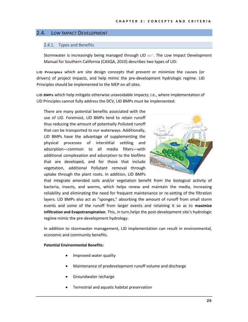
Stormwater is increasingly being managed through LID . The Low Impact Development Manual for Southern California (CASQA, 2010) describes two types of LID:
LID Principles which are site design concepts that prevent or minimize the causes (or drivers) of project impacts, and help mimic the pre-development hydrologic regime. LID Principles should be implemented to the MEP on all sites.
LID BMPs which help mitigate otherwise unavoidable impacts; i.e., where implementation of LID Principles cannot fully address the DCV, LID BMPs must be implemented.
There are many potential benefits associated with the use of LID. Foremost, LID BMPs tend to retain runoff thus reducing the amount of potentially Polluted runoff that can be transported to our waterways. Additionally, LID BMPs have the advantage of supplementing the physical processes of interstitial settling and adsorption—common to all media filters—with additional complexation and adsorption to the biofilms that are developed, and for those that include vegetation, additional Pollutant removal through uptake through the plant roots. In addition, LID BMPs that integrate amended soils and/or vegetation benefit from the biological activity of bacteria, insects, and worms, which helps renew and maintain the media, increasing reliability and eliminating the need for frequent maintenance or re-setting of the filtration layers. LID BMPs also act as “sponges,” absorbing the amount of runoff from small storm events and some of the runoff from larger events and retaining it so as to maximize infiltration and Evapotranspiration. This, in turn,helps the post-development site’s hydrologic regime mimic the pre-development hydrology.
In addition to stormwater management, LID implementation can result in environmental, economic and community benefits.
Potential Environmental Benefits:
• Improved water quality
• Maintenance of predevelopment runoff volume and discharge
• Groundwater recharge
• Terrestrial and aquatic habitat preservation

C H A P T E R 2 : C O N C E P T S A N D C R I T E R I A
26
• Reduced potable water demand
• Recycling and beneficial reuse
• Reduction in urban heat island effect
Potential Economic Benefits:
• Reduced construction and maintenance costs
• Improved marketability
• Energy cost reduction and water conservation
Potential Community Benefits:
• Improved aesthetic value
• Provides “green job” opportunities
• Educational opportunities
2.4.2. Requirements and Prioritization
The 2010 SAR MS4 Permit requires implementation of both LID Principles and LID BMPs through the following provisions:
XII.E.3.—The Co-Permittees shall require that New Development and Significant Redevelopment projects include Site Design BMPs during the development of the Project-Specific WQMP. The design goal shall be to maintain or replicate the pre-development hydrologic regime through the use of design techniques that create a functionally equivalent post-development hydrologic regime through site preservation techniques and the use of integrated and distributed infiltration, retention, detention, evapotranspiration, filtration and treatment systems.
and
XII.E.7.—To reduce Pollutants in Urban Runoff, address Hydromodification, and manage Urban Runoff as a resource to the MEP, the revised WQMP shall specify preferential use of Site Design BMPs that incorporate LID techniques, where feasible, in the following manner (from highest to lowest priority):
a. Preventative measures (these are mostly non-structural measures, e.g., preservation of natural features to a level consistent with the MEP standard;

C H A P T E R 2 : C O N C E P T S A N D C R I T E R I A
27
minimization of Urban Runoff through clustering, reducing impervious areas, etc.) and
b. Mitigation measures (these are structural measures, such as infiltration, harvesting and use, bio-treatment, etc.)
Additionally, Provision XII.D.7.b of the MS4 Permit requires this WQMP to include an updated list of Treatment Control BMPs, including an evaluation of effectiveness based on national, statewide or regional studies. It is now widely accepted that LID BMPs provide highly effective and reliable stormwater treatment for a wide range of potential stormwater pollutants, including 303(d) listed pollutants. Further, Provision XII.E.2 of the MS4 Permit requires the use of LID BMPs that infiltrate, harvest and use, evapotranspire, biotreat and/or detain runoff. The LID BMPs listed in Chapter 4 infiltrate, harvest and use, and evapotranspire runoff to the extent feasible, and provide highly effective biotreatment for the remaining runoff, resulting in robust pollutant-removal performance with low maintenance requirements. Consistent with MS4 Permit Provision XII.E.4, this WQMP promotes green infrastructure/LID techniques including, but not limited to the following:
a. Allow permeable surface designs in low traffic roads and parking lots.
b. Allow natural drainage systems for street construction and catchments (with no drainage pipes) and allow vegetated ditches and swales where feasible.
c. Require landscape in parking lots to provide treatment, retention or infiltration.
d. Reduce curb requirements where adequate drainage, conveyance, treatment and storage are available.
e. Allow no curbs, curb cuts and/or stop blocks in parking areas and residential streets with low traffic.
f. Use of green roof, rain garden, and other green infrastructure in urban/suburban area.
g. Allow rainwater harvesting and use.
h. Narrow streets provide alternatives to minimum parking requirements, etc. to facilitate LID where acceptable to public safety departments.
i. Consider vegetated landscape for stormwater treatment as an integral element of streets, parking lots, playground and buildings.
j. Landscaping designs that promote longer water retention and evapotranspiration such as 1-foot depth of compost/top soil in commercial and residential areas on top of 1 foot of non-compacted subsoil, concave landscape grading to allow runoff from

C H A P T E R 2 : C O N C E P T S A N D C R I T E R I A
28
impervious surfaces, and water conservation by selection of water efficient native plants, weather-based irrigation controllers, etc.
LID BMP Prioritization
In addition to requiring implementation of LID BMPs as described above, the 2010 SAR MS4 Permit also prioritizes which LID BMPs should be used first.
XII.E.2.
• Projects subject to the WQMP requirements must ‘Infiltrate, harvest and use, evapotranspire and/or bio-treat the DCV.’
• A properly engineered and maintained bio-treatment system may be considered only if infiltration, harvesting and use and evapotranspiration cannot be feasibly implemented at a project site.
• Any portion of the design capture volume that is not infiltrated, harvested and used, evapotranspired, and/or biotreated shall be treated and discharged in accordance with the requirements set forth in Section XII.G [alternatives and in-lieu programs].
XII.E.2. further states that:
• It is recognized that LID principles are not universally applicable and they are dependent on factors such as soil conditions including soil compaction and permeability, groundwater levels, soil contaminants (Brownfield development), space restrictions (in-fill projects, redevelopment projects, high density development, transit-oriented developments), and highest and best use of Urban Runoff (to support downstream uses), etc.
Therefore, to ensure that the most effective BMPs are used on each project, MS4 Permit Provision XII.G.1 requires the Co-Permittees to develop technically-based feasibility criteria for LID BMPs. These feasibility criteria are identified in the sections below.
All LID BMPs must be designed and implemented with measures to avoid the creation of Nuisance or Pollution associated with vectors, such as mosquitoes, rodents and flies.
2.4.3. LID Retention BMPs vs LID Bioretention BMPs
The 2010 SAR MS4 Permit requires the DCV to be retained and infiltrated onsite. When onsite LID Infiltration BMP methods are proven to be infeasible, then a feasibility analysis regarding harvest and reuse must be considered. When such retention methods are infeasible, the remainder of the DCV can be treated via processes such as bioretention. The

C H A P T E R 2 : C O N C E P T S A N D C R I T E R I A
29
intent behind these prioritization requirements is to maximize onsite retention, so as to reduce the volume of urban runoff and Pollutant loads entering Receiving Waters. In cases where such retention practices are feasible, they may provide a significant benefit to runoff quality, and help the project mimic the pre-development hydrologic regime.
BMPs solely reliant on LID Retention practices (infiltration, harvesting and use, or evapotranspiration), however, require a high level of confidence in the long-term reliability of the infiltration characteristics of the underlying soils, water demand, and of evapotranspiration rates, respectively, to ensure timely drawdown of the storage volume. It is impracticable to accurately predict, in many cases, whether the required drawdown will occur, as actual infiltration and evapotranspiration rates vary widely and are inherently unpredictable, and non-potable water usage rates must be consistent throughout the year, including the Wet Season.
The 2010 SAR MS4 Permit’s retention prioritization requirements discussed above, however, make no explicit mention that this retention storage must be recovered so that subsequent runoff events can be managed. Without a demand criterion, it would be possible that a facility could be designed to capture the DCV, but with insufficient demand for timely drawdown this condition would cause health concerns through vector and mosquito breeding. Furthermore, the condition could cause excessive overflows and bypasses of the facility, and thus the intent of the Santa Ana Regional Board requirements in this regard would not be fulfilled.
When appropriately designed, LID Bioretention BMPs, such as shown in the LID BMP Design Handbook, inherently meet the goal of capturing the required volume of urban runoff, and infiltrating and evapotranspiring that volume to the extent feasible given site soils and other conditions. In highly permeable soils, infiltration will meet or exceed the required DCV; in less permeable soils the proportion infiltrated will be smaller and the remaining proportion will either be evapotranspired or receive biotreatment. Such bioretention LID BMPs will achieve the maximum feasible level of infiltration and evapotranspiration and achieve the minimum feasible (but highly biotreated) discharge to the MS4. LID Bioretention BMPs also provide a higher level of confidence that the captured volume will be drained within an acceptable timeframe.
A retrofit project being implemented by the District is constructing and testing bioretention BMPs and will directly monitor and quantify the volume reduction benefits of those BMPs over the next several years. Additionally*, a recent analysis of the monitored inflow and outflow data contained in the International Stormwater BMP Database showed an average long-term volume reduction on the order of 40 percent for biofilters, 30 percent for
* Adapted from the Orange County Technical Guidance Document, 2011

C H A P T E R 2 : C O N C E P T S A N D C R I T E R I A
30
extended detention basins, and 60 percent for Bioretention BMPs. These values represent the average of observed total volume reductions through infiltration and transpiration during entire monitoring studies. Total volume reductions during a study were calculated based on comparison of the total inflow and outflow volumes measured over the duration of each study (including multiple — up to 65 storm events). As these analyses utilized long-term observed volume reductions over a series of storm events, they provide a benchmark for comparing the performance of LID Retention BMPs (Infiltration, Harvest and Use, and Evapotranspiration) against the performance of LID Biotreatment BMPs including Bioretention, which under some circumstances may provide a similar level of retention plus offer other pollutant treatment mechanisms.
This analysis shows that while LID Bioretention BMPs are not designed to fully retain the DCV, on an average basis they are capable of providing substantial volume reductions, on the order of half of the water that is captured and managed. This analysis further shows that a well-designed LID Bioretention BMP that has been designed to capture 80 percent of average annual stormwater runoff and has been designed to achieve maximum feasible volume reduction would be expected to achieve total long-term volume reduction on the order of 40 percent of long-term runoff volume. This means that a designer, faced with an LID Retention BMP with a long-term performance of 40 percent DCV retention or less, could substitute that BMP with a LID Bioretention BMP that is capable of carrying 100 percent of the DCV without impairing the overall performance of the site’s system of BMPs. This is because roughly 40 percent or more of the DCV will be incidentally infiltrated or evapotranspired by the LID Bioretention BMP — roughly equal or better than a potentially lower performing LID Retention BMP.
The 2010 SAR MS4 Permit’s preferential hierarchy is met by designating 40 percent retention as a minimum threshold for eliminating the mandatory selection and use of a specific LID Retention BMP in favor of using LID Bioretention BMPs that achieve a comparable or greater level of retention for the system as a whole. As discussed, infiltration in such LID Bioretention BMPs is provided to the maximum extent allowable by the underlying soil conditions. The 40 percent threshold is applicable on the Drainage Management Area (DMA) level and must not be used to reduce the site’s overall level of retention.
For example, if 40 percent of a project site’s soils can infiltrate well, DMAs in those areas of the site will use infiltration and consequently 40 percent of the project’s DCV will be infiltrated. The balance of the DMAs that were not able to infiltrate will utilize additional LID BMPs lower in the hierarchy.

C H A P T E R 2 : C O N C E P T S A N D C R I T E R I A
31
2.4.4. Highest and Best Use
Finding II.G.14 states that:
Consideration of “highest and best use” of the discharge should also be considered. For example, Lake Elsinore is evaporating faster than runoff from natural precipitation can recharge it. Requiring infiltration of 85 percent of runoff events for projects tributary to Lake Elsinore would only exacerbate current water quality problems associated with Pollutant concentration due to lake water evaporation. In cases where rainfall events have low potential to recharge Lake Elsinore (i.e., no hydraulic connection between groundwater to Lake Elsinore, or other factors), requiring infiltration of Urban Runoff from projects is counterproductive to the overall watershed goals. Project proponents, in these cases, would be allowed to discharge Urban Runoff, provided they used equally effective filtration-based BMPs.
As a significant portion of the San Jacinto sub-watershed that drains to Lake Elsinore is expected to develop or re-develop over time, most urban areas will be subjected to the LID requirements identified in the MS4 Permit, including the ‘Tier 1’ requirement to retain runoff. The CNRP that will be submitted to the Regional Board on December 31, 2011, will further assess potential negative impacts of retention upon the beneficial uses of Lake Elsinore. The final form of the CNRP may include specific exceptions to retention within this sub-watershed. As such time that the CNRP is approved by the Regional Board, this WQMP will be amended as necessary to reflect such requirements.
2.4.5. LID Infiltration BMPs
In many areas of Riverside County, soils will support LID Infiltration BMPs. However, there are several factors that affect their feasibility that must be considered before utilizing such BMPs. Some of the factors will require a licensed Geotechnical Engineer to verify, as identified in the sub-sections below.
Groundwater Protection
The MS4 Permit Provision XII.D.8. states minimum requirements to protect groundwater when BMPs that infiltrate stormwater are used. The requirements apply to “treatment control BMPs utilizing infiltration” but not to “BMPs not designed to primarily function as infiltration devices.” Infiltration trenches and infiltration basins are designated here to be “treatment control BMPs utilizing infiltration.”
In accordance with XII.D.8., infiltration BMPs cannot be used if the BMPs location meets any of the scenarios below. Verification of this information can be done using past

C H A P T E R 2 : C O N C E P T S A N D C R I T E R I A
32
geotechnical investigations for the site, or using publically available information. If those sources are unavailable, a licensed Geotechnical Engineer may be required.
• Areas of known soil or groundwater contamination (unless with written authorization from the Regional Board Executive Officer)
• Located less than 100 feet horizontally from any water supply well
• Located so that the bottom of the BMP is less than 10 feet above the “historic high groundwater mark,” except in areas where groundwater does not support beneficial uses
In accordance with XII.D.8., infiltration BMPs cannot be used in the following locations unless adequate pretreatment is provided:
• Gas stations
• Large commercial parking lots
• Areas of industrial or light industrial activity
• Areas subject to high vehicular traffic (25,000 or greater average daily traffic)
• Car washes, nurseries, or other areas with pollutant sources that could pose a high threat to water quality, as determined by Co-Permittee staff
Slope / Structural Stability:
• LID Infiltration BMPs shall not be used in locations or in soils that may create a public safety or structural concern, such as but not limited to slope or structural in-stability, landslides, mudslides, liquefaction or other geotechnical concerns. Such a determination must be in accordance with the recommendations of a licensed Geotechnical Engineer. In such a scenario, other LID BMPs would be required, and an impermeable barrier may be required so the facility is “flow through” and all biotreated runoff is under-drained away from the facility.
Infiltration Characteristics
BMPs entirely reliant on infiltration (such as infiltration basins or infiltration trenches) require a high level of confidence in the long-term reliability of the infiltration characteristics of the underlying soils. Adequate long-term infiltration capacity is the determining factor as to whether an infiltration BMP will be effective for the protection of water quality.
‘In-Situ’ tested infiltration rates (i.e., the Saturated Hydraulic Conductivity) are known to vary widely both spatially and temporally. At a given point in time, it is not uncommon to
C H A P T E R 2 : C O N C E P T S A N D C R I T E R I A
33
find that the tested infiltration rates at one location can be an order of magnitude different from another test conducted a matter of feet away – even within the same BMP footprint. Additionally it is known that the infiltration rate is typically reduced after construction of the project (compared to exploratory/feasibility testing performed before construction) due to grading, cut and fill conditions; and that the infiltration rate continues to further degrade over time due to unavoidable / inadvertent clogging of the native soils.
The risk is that if the actual long-term infiltration rates within the BMP are too low, excessive ponding may occur, which has two negative effects: 1) mosquitoes and other vectors may begin breeding, and 2) subsequent rainfall events may bypass the BMP, resulting in untreated runoff being discharged from the site and potential impacts to waterbodies.
To avoid creation of nuisance or vector conditions in accordance with MS4 Permit Provision XII.K.1, a maximum Drawdown Time of 72 hours has been established. To ensure that over the life of the BMP the actual Drawdown Time does not exceed 72 hours, and based on the typical infiltration basin depth of 5 feet, the minimum long-term post-development infiltration rate must be at least 0.83 inches per hour (5ft * 12 / 72 hours = 0.83 inches/hour). As discussed above however, the long-term post-development infiltration rates can be much lower than the initial (pre development) infiltration rates that are measured for feasibility testing. As such, infiltration testing requirements have incorporated a minimum safety factor of 2 for LID Infiltration BMPs. Incorporating the established minimum factor of safety, the tested pre-development infiltration rates must be greater than 1.6 inches per hour to be assured that, over the life of the BMP, nuisance or vector conditions will not be created. This will also ensure that the BMP will be adequately drained in the event of back-to-back storms. Accordingly the following feasibility criteria have been developed to ensure that the most effective BMPs are deployed:
• If the average ‘in-situ’ tested infiltration rate for the site is less than 1.6 inches per hour, LID Infiltration BMPs (infiltration basins, infiltration trenches, etc.) shall not be used. Infiltration testing needs to be performed using approved methodologies, such as those identified in the LID BMP Design Handbook. The analysis used to determine the threshold infiltration rates was based on factors of safety used in the adopted Orange County WQMP/Technical Guidance Document, standard engineering practices, and best professional judgment. Appendix VII (“Infiltration Rate Evaluation Protocol and Factor of Safety Recommendations”) of the “Orange County Technical Guidance Document for the Preparation of Conceptual/Preliminary and/or Project Water Quality Management Plans” was consulted.
Table 4-5 of the WQMP includes specific direction regarding LID Bioretention and the assumed infiltration capacity.

C H A P T E R 2 : C O N C E P T S A N D C R I T E R I A
34
If the project meets the following criteria:
Residential Commercial, Institutional
Industrial
Less than 10 acres and less than 30 DU
Less than 5 acres and less than 50,000 SF Impervious
Less than 2 acre and less than 20,000 SF Impervious
Then the project is considered a small project. If the small project is underlain with Hydrologic Soils Group (HSG) “D” soils according to available regional soils maps, and no available data for the site is conflicting with such a designation, ‘in-situ’ testing of infiltration rates may not be required, at the discretion of the Co-Permittee. In this case, LID Infiltration BMPs shall not be used. The exemption for Group D soils only applies to LID Infiltration BMPs to help prevent ponding and vector concerns. For DMAs where LID Infiltration BMPs are not feasible (and where Harvest and Use BMPs have been ruled out), the WQMP then requires the use of bioretention type BMPs. Bioretention BMPs are designed to maximize infiltration to the MEP but also have additional attributes that are designed to reduce and treat the volume of runoff for water that may not infiltrate; thereby substantially reducing vector concerns.
While soil amendment practices can affect evapotranspiration rates, they do not have as substantial an effect on infiltration rates to the surrounding native soils and are not appropriate to prevent vector concerns in structural LID BMPs. Amended soils are highly recommended for self-retaining areas (micro-infiltration areas), when sited on Group C and D soils.
Cut and Fill Conditions
If the BMP would be placed in a fill condition and the infiltration surface of the BMP cannot extend down into native soils, or if the BMP would be placed in a cut condition and there is no practicable way to verify infiltration rates at the final BMP elevation, LID Infiltration BMPs shall not be used. LID Infiltration BMPs will be implemented where feasible on a DMA level. Though LID Infiltration BMPs should not be used for DMAs containing cut and fill areas, they can be used for DMAs in other parts of a project site in which infiltration is feasible. Each DMA on a project site will be assessed accordingly. The soil beneath the basin must be thoroughly evaluated in a geotechnical report since the underlying soils are critical to the basin’s long term performance. Because of this, the project proponent must be able to perform tests on the actual soils that will exist at the infiltration surface. It is impossible to test the infiltration rate of an engineered fill that does not yet exist. As such, LID Infiltration BMPs would only be prohibited if the planned fill was so deep that the bottom of the

C H A P T E R 2 : C O N C E P T S A N D C R I T E R I A
35
LID Infiltration BMP could not extend down through the native soils. A similar, unknown situation exists for those areas that will be cut as part of the site grading process.
Other Site Specific Factors
If the geotechnical investigation, performed by a licensed engineer, discovers other site-specific factors that would preclude effective infiltration, such as, but not limited to, clay lenses or restrictive layers, LID Infiltration BMPs are not required in those areas.
2.4.6. LID Harvest and Use
Harvest and Use BMPs may be employed on any site where it can be shown there is sufficient reliable and timely demand for non-potable water, subject to the following criteria:
Water Rights:
• If harvesting and using stormwater runoff would negatively impact downstream water rights, Harvest and Use BMPs are not required. The Permit requires design approaches associated with a certain DCV. In some cases, adherence to the DCV standard does not coincide with the basic LID principle of mimicking the pre-development hydrologic condition.
Code Compliance:
• Any structures and proposed water storage tanks shall conform to local and state building codes and regulations.
Reclaimed Water Use:
Utilizing reclaimed water where available inherently reduces the amount of treated municipal effluent discharged to waterbodies. Further, utilizing the capacity of the reclaimed water system, where available, has a significantly larger benefit for offsetting potable water supply than stormwater Harvest and Use BMPs. If reclaimed water is available to the site, the use of reclaimed water will take precedence over the harvest and use of stormwater runoff. If reclaimed water will be used on the project, there is no need to further evaluate the feasibility of Harvest and Use BMPs. Document the use of reclaimed water in your Project-Specific WQMP.*
* Non-agricultural irrigation using recycled water must comply with the statewide permit for Landscape Irrigation Using Recycled Water and the State Department Health guidelines.

C H A P T E R 2 : C O N C E P T S A N D C R I T E R I A
36
Criteria
The evaluation of the feasibility of Harvest and Use BMPs is performed for three potential categories of use: toilet flushing, irrigation, and other on-site non-potable uses.
For evaluation of toilet flushing, flush volumes and use rates from the literature have been combined with a long-term continuous simulation to develop a minimum demand, referred to as the Toilet Users To Impervious Area (TUTIA) ratio, that would be required to achieve the minimum 40 percent long-term retention of runoff. See Table 2-2 below, as well as the discussion of LID Retention vs. LID Bioretention BMPs above.
• If the proposed project does meet or exceed this minimum demand, implementing this Harvest and Use BMP would be less effective than a Bioretention BMP, and as such, this Harvest and Use BMP would not be required for the project.
TABLE 2-2. Harvest and Use Data for Toilet Use
Project type Residential Retail / Office Commercial Industrial Schools
Basis of Use Type Resident Employee
(non-visitor) Employee
(non-visitor) Employee
(non-student) Design Capture Storm depth, in
Minimum toilet users per tributary impervious acre for partial capture (tu/ac)
0.50 85 114 142 24
0.55 93 123 158 26
0.60 101 132 172 29
0.65 108 141 185 31
0.70 116 150 198 33
0.75 123 159 208 35
0.80 131 167 219 37
0.85 138 176 229 39
0.90 145 184 238 40
0.95 152 193 247 42
1.00 159 201 255 43
1.05 166 209 263 44
1.10 172 217 271 45
1.15 179 225 278 46
1.20 185 233 285 47

C H A P T E R 2 : C O N C E P T S A N D C R I T E R I A
37
AUnit demands used in analysis: Residential = 9.3 gal/resident/day
Retail/office = 7 gal/employee/day
Industrial = 5.5 gal/employee/day
Schools = 33 gal/employee/day
For evaluation of irrigation, typical evapotranspiration and water demands have been combined with a long-term continuous simulation, to develop a minimum ratio of Effective Irrigated Area per Tributary Impervious Area (EIATIA) that would be required to achieve the minimum 40 percent long-term retention of runoff. See Table 2-3 below, as well as the discussion of LID Retention vs. LID Bioretention BMPs above. For the purposes of this assessment, landscaping will either be a ‘Conservation Design’ (Low water use, native species, etc.), or ‘Active Turf areas’ (higher water use species such as conventional sod).
TABLE 2-3. Harvest and Use Data for Irrigation UseA, B
General Landscape Type
Conservation Design: KL=0.35 Active Turf Areas: KL
C=0.70
Design Capture Storm Depth, in
Minimum Required Effective Irrigated Area per Tributary Impervious Acre for partial capture (ac/ac)
0.50 0.26 0.22 0.55 0.52 0.35 0.60 0.79 0.47 0.65 1.05 0.60 0.70 1.32 0.72 0.75 1.59 0.85 0.80 1.85 0.98 0.85 2.12 1.10 0.90 2.38 1.23 0.95 2.65 1.35 1.00 2.92 1.48 1.05 3.18 1.60 1.10 3.45 1.73 1.15 3.71 1.85 1.20 3.98 1.98
AET data from the CIMIS station at U.C. Riverside used for this analysis. BTo use this table, select the Design Storm for your project area. Then select the planting/irrigation management type (i.e., conservation versus active turf). The resulting value gives the minimum required irrigated area per tributary area for stormwater capture which will be used in Step 3 of D.2 in the Template. . CKL = Landscape Coefficient, KL = Ks × Kd × Kmc where Ks = species factor, Kd = density factor and Kmc = microclimate factor. The landscape coefficient (KL) incorporates plant species, microclimate and water management/irrigation practices as adapted from Appendix X of the 2011 Orange County Technical Guidance Document located here: http://www.ocwatershed.com/WQMP.aspx For the table above, the lower value corresponds to water conservation practices and the higher value corresponds to traditional irrigation practices for grass turf. Each Co-Permittee has a model ordinance based on AB 1881. Specifying certain high water use plants contradicts the intent of AB 1881.

C H A P T E R 2 : C O N C E P T S A N D C R I T E R I A
38
• If the proposed project cannot meet or exceed this ratio, implementing this Harvest and Use BMP would be less effective than a bioretention BMP, and as such this Harvest and Use BMP would not be required for the project. This approach provides for full treatment on a DMA by DMA basis with LID BMPs. The most applicable LID BMP treatment, following the hierarchy outlined in the 2010 SAR MS4 Permit, is proposed for each DMA.
For evaluation of other non-potable uses for which minimum ratios as described above have not been developed, such as industrial uses or washing, a long-term continuous simulation of precipitation intensity and frequency has been performed to develop a table of minimum demands that would be required to achieve the minimum 40 percent long-term retention of runoff. See Table 2-4 below, as well as the discussion of LID Retention vs. LID Bioretention above.
• If the proposed project cannot meet or exceed these minimum demands, implementing this Harvest and Use BMP would be less effective than a Bioretention Treatment Control BMP, and as such this Harvest and Use BMP would not be required for the project.
TABLE 2-4. Harvest and Use Data for Other Non-Potable Uses*
Design Capture Storm depth, in
Wet season demand required for minimum partial capture, gpd per impervious acre
0.50 781 0.55 869 0.60 947 0.65 1,018 0.70 1,089 0.75 1,147 0.80 1,204 0.85 1,259 0.90 1,310 0.95 1,359 1.00 1,403 1.05 1,448 1.10 1,490 1.15 1,530 1.20 1,568
*Design Capture Storm = 0.5 in was calculated using Lake Mathews rainfall; 0.7 in with Lake Elsinore rainfall; 1.0 in with Temecula rainfall. For Design Storms between 0.5 and 1.0 inches, the values were interpolated from the values computed for the three stations.

C H A P T E R 2 : C O N C E P T S A N D C R I T E R I A
39
For Design Storms greater than 1 inch, the values were extrapolated based on the relationship between the Lake Elsinore and Temecula stations. Wet season defined as the annual time period between October and April.
Storage of a smaller volume of runoff for later use - Even if the available demand is less than the minimum required, incidental harvesting of stormwater runoff is encouraged for water conservation and environmental stewardship purposes, however:
• Such incidental harvesting of stormwater runoff is not required and may not be credited toward addressing HCOCs.
Minimum Demands
Tables 2-1, 2-2 and 2-3 provide minimum demands to provide for reuse of 40 percent of the total runoff. Data presented in the tables were generated based upon a continuous simulation analysis and demand factors consistent with similar analyses prepared for the Orange County WQMP. Parameters used in the development of the following tables are consistent with criteria set forth in the corresponding analysis for Orange County. Riverside County specific rainfall data was used to generate the analysis. Section X.3, “Planning Level Harvest and Use Feasibility Thresholds” of the “Orange County Technical Guidance Document for the Preparation of Conceptual/Preliminary and/or Project Water Quality Management Plans”, was consulted when deriving Tables 2-1, 2-2 and 2-3. The wet season demand is defined as the minimum combined project demand required for minimum partial capture for the range of precipitation zones found in the Santa Ana Region of Riverside County. Projects with a total demand below this value are not required to prepare a project specific evaluation of Harvest and Use BMP feasibility.
2.4.7. LID Bioretention
Experience has shown implementation of LID Bioretention BMPs is feasible on nearly all development sites with sufficient advance planning. When appropriately designed, LID Bioretention BMPs, particularly when designed in accordance with the LID BMP Design Handbook, also inherently met the goal of capturing the required volume of urban runoff, and infiltrating and evapotranspiring that volume to the extent feasible given site soils and other conditions. In highly permeable soils, infiltration will meet or exceed the required DCV; in less permeable soils the proportion infiltrated will be smaller and the remaining proportion will either be evapotranspired or receive biotreatment. Such LID BMPs will achieve the maximum feasible level of infiltration and evapotranspiration and achieve the minimum feasible (but highly biotreated) discharge to the MS4.
Projects where LID Bioretention may not always be feasible generally fall into one of the following two categories:
• Portions of sites not being developed or redeveloped, but which must be retrofitted to meet treatment requirements pursuant to the “50 percent rule.”

C H A P T E R 2 : C O N C E P T S A N D C R I T E R I A
40
For many scenarios, LID bioretention will be feasible. If site specific conditions preclude LID treatment of existing impervious surfaces on the newly developed portion of the site – and if treatment of the existing impervious surfaces cannot be otherwise treated – then the project proponent must prove infeasibility. In these special situations, LID BMPs shall be used for the maximum amount of the project’s impervious area that is feasible. For impervious areas of the project where the Co-Permittee has approved that site-specific LID BMPs are not feasible, other Treatment Control BMPs approved by the Co-Permittee must be implemented to achieve the same level of compliance.
• Sites smaller than one acre approved for lot-line to lot-line development or redevelopment as part of a Co-Permittee’s effort to preserve or enhance a pedestrian-oriented “smart-growth” type of urban design. For many scenarios, LID bioretention options such as planters will be feasible.
If other site conditions may preclude the use of LID, a detailed site-specific feasibility analysis may be submitted as part of the preliminary Project-Specific WQMP. Site-specific determinations shall be certified by a Professional Civil Engineer registered in the State of California, and must be approved by the Co-Permittee. Such site-specific determinations are expected to rarely be necessary; as such, if your project has truly extenuating circumstances and you plan to submit a site-specific determination, it is highly recommended to discuss this with Co-Permittee staff early on.
In these special situations, where it may still be feasible to treat runoff from one or more Drainage Management Areas with LID, LID shall be used for the maximum amount of the project’s impervious area that is feasible. For impervious areas of the project where the Co-Permittee has approved a site-specific determination that LID BMPs are not feasible, other Treatment Control BMPs approved by the Co-Permittee must be implemented to achieve the same level of compliance.
2.4.8. Other Considerations
Table 2-4 provides the recommended percentage of a project site that is required to be made available for LID BMPs. The project may provide more area for LID BMPs if desired. Table 2-4 is intended to be used as follows:
If, in order to manage the entire DCV, the percentage of the site that would have to be made available for LID BMPs exceeds the project-type specific minimum criteria shown in the table, then the remaining volume must be addressed with other Treatment Control BMPs, Credits, Urban Runoff fund contributions, or waivers.

C H A P T E R 2 : C O N C E P T S A N D C R I T E R I A
41
If the percentage of the site provided for LID BMPs is lower than the value shown in Table 2-4 and the DCV cannot be fully managed, a reviewer can request that additional area be made available for BMPs in the site design until either the percentage of the site in Table 2-5 is provided or the entire DCV is managed, whichever is less.
TABLE 2-5. Recommended Effective Area1 Required to be made Available for LID BMPs (% of site)2
Priority Development Project Type New Development Redevelopment
SF/MF Residential < 7 du/ac 10% 5%
SF/MF Residential 7 – 18 du/ac 7% 3.5%
SF/MF Residential > 18 du/ac 5% 2.5%
Mixed Use, Commercial/Industrial w/ FAR < 1.0 10% 5%
Mixed Use, Commercial/Industrial w/ FAR 1.0 – 2.0 7% 3.5%
Mixed Use, Commercial/Industrial w/ FAR > 2.0 5% 2.5%
Podium (parking under > 75% of project) 3% 1.5%
Zoning allowing development to property lines 2% 1%
Transit Oriented Development3 5% 2.5%
Parking 5% 2.5% 1 “Effective area” is defined as area which 1) is suitable for a BMP (for example, if infiltration is potentially feasible for the site based on infeasibility criteria, infiltration must be allowed over this area) and 2) receives runoff from impervious areas. 2 See San Bernardino County Stormwater Program Technical Guidance Document for Water Quality Management Plans (WQMP) for more information regarding this table. 3Transit oriented development is defined as a development with development center within one half mile of a mass transit center. Key: du/ac = dwelling units per acre, FAR = Floor Area Ratio = ratio of gross floor area of building to gross lot area, MF = Multi Family, SF = Single Family
2.4.9. Hydromodification and BMP Design
To help prevent Hydromodification impacts, the 2010 SAR MS4 Permit specifies requirements for identifying and mitigating HCOCs. HCOC requirements are separate from, but overlap, the LID requirements of the 2010 SAR MS4 Permit.
Hydromodification control approaches have evolved over time, with efforts first focused on managing peak flow rates. The approaches have now shifted to matching the volume and timing of an event hydrograph. This can be accomplished through the use of Structural BMPs designed to control the post-construction runoff hydrograph from the site. The LID Design process described in this document will significantly reduce, and in some cases eliminate entirely, any potential HCOCs from a project.

C H A P T E R 2 : C O N C E P T S A N D C R I T E R I A
42
2.5. SELECTION OF PERMANENT SOURCE CONTROL BMPS
Based on identification of potential Pollutants of Concern associated with various types of facilities, the Stormwater Pollutant Sources/Source Control Checklist (included as part of the Project-Specific WQMP Template in Exhibit B) summarizes source controls associated with each facility type. This approach ensures appropriate BMPs are applied to potential sources of each Pollutant of Concern.
References and Resources The Importance of Imperviousness (Tom Scheuler, 1995)
Site Planning for Urban Stream Protection, available from the Center for Watershed Protection)
California Stormwater BMP Handbooks Southern California LID Manual Urban Runoff Quality Management, Water Environment Federation and
American Society of Civil Engineers, 1998. ISBN 1-57278-039-8 ISBN 0-7844-0174-8. Stormwater Infiltration, Bruce K. Ferguson, 1994. ISBN 0-87371-987-5 Clean Water Act Section 402(p) 40 CFR 122.26(d)(2)(iv)(A)(2) – Stormwater Regulations for New Development Restoring Streams in Cities (Riley, 1998) Stream Restoration: Principles, Processes, and Practices
(Federal Interagency Stream Restoration Working Group, 1998, revised 2001) Municipal Handbook, Rainwater Harvesting Policies (USEPA, 2008) Green Roofs for Stormwater Runoff Control (USEPA, 2009a) Porous Pavements (Ferguson, 2005) Orange County WQMP and TGD, with errata, 2011 CASQA LID Guidance Manual for Southern California RWQCB Water Quality Control Plan for the San Diego Basin (Basin Plan) Design Handbook for Low Impact Development Best Management Practices, Riverside County Flood Control and
Water Conservation District, 2011.

W A T E R Q U A L I T Y M A N A G E M E N T P L A N F O R T H E S A N T A A N A R E G I O N O F R I V E R S I D E C O U N T Y
43
3.0 PREPARING YOUR PROJECT-SPECIFIC WQMP
Step-by-step assistance to document compliance.
Your Project-Specific WQMP template (refer to Exhibit B) will demonstrate your project complies with all applicable requirements of the 2010 SAR MS4 Permit — to minimize imperviousness, retain or detain stormwater, slow runoff rates, incorporate required source controls, treat stormwater prior to discharge from the site, control runoff volumes if required, and provide for operation and maintenance of Stormwater BMPs.
Every Co-Permittee listed at the beginning of this document requires a Project-Specific WQMP for every applicable project. The Project-Specific WQMP must be submitted with your application for Discretionary Approvals and must have sufficient detail to ensure the stormwater design, site plan, and landscaping plan are congruent. The level of detail will vary based on what is known about the project at the time that Discretionary Approvals are sought. Even a preliminary Project-Specific WQMP must demonstrate that adequate area is being set aside to meet the BMP requirements of the WQMP. Submitting a complete and thorough Project-Specific WQMP will facilitate quicker review and fewer cycles of review.
Utilizing the template provided in Exhibit B, your Project-Specific WQMP will consist of a report, exhibits, and reference to long-term maintenance and funding plan. The purpose of this template is to assist you with documenting compliance for your project. Co-Permittee staff must use a checklist, such as the one provided in Exhibit F to assist in plan checking Project-Specific WQMPs. It may also be used by the preparer of the project specific WQMP to help ensure compliance with the criteria in this Guidance Document.
Plan and design your stormwater controls integrally with the site planning and landscaping for your project. It’s best to start with general project requirements and preliminary site design concepts; then prepare the detailed site design, landscape design, and Project-Specific WQMP
Chapter
3
I C O N K E Y
Helpful Tip
Submittal Requirement
Terms to Look Up
References & Resources

C H A P T E R 3 : P R E P A R I N G Y O U R P R O J E C T - S P E C I F I C W Q M P
44
simultaneously. This will help ensure that your site plan, landscape plan, grading plan and Project-Specific WQMP are congruent. See A.1 of the WQMP Template in Exhibit B for the minimum features to show on your WQMP site plan.
The following step-by-step procedure should optimize your design by identifying the best opportunities for stormwater controls early in the design process.
The recommended steps are:
1. Assemble needed information
2. Identify site opportunities and constraints
3. Follow the LID design guidance to analyze your project for LID and to develop and document your drainage design
4. Document any alternative compliance
5. Specify source controls using the Pollutant Sources/Source Control checklist from the Project-Specific WQMP Template in Exhibit B
6. Plan for ongoing maintenance of Stormwater BMPs
7. Complete the Project-Specific WQMP
Co-Permittee staff may recommend you prepare and submit a preliminary Project-Specific WQMP prior to formally applying for planning and zoning approvals. Your preliminary Project-Specific WQMP should incorporate a conceptual plan for site drainage, including self-treating and self-retaining areas and the location and approximate sizes of any Stormwater BMPs. This additional up-front design effort will save time and avoid potential delays later in the review process.
Use of the Project-Specific Template located in Exhibit B can facilitate the Project-Specific WQMP development process.
3.1. ASSEMBLE PROJECT AND SITE INFORMATION
To perform the LID design, the designer needs to know the following site characteristics:
Existing natural hydrologic features and natural resources, including any contiguous natural areas, wetlands, watercourses, seeps, or springs.
Existing site topography, including contours of any slopes of 4 percent or steeper, general direction of surface drainage, local high or low points or depressions, and any outcrops or other significant geologic features.
WQMP Template For use in preparing and
documenting your WQMP compliance, a Project-
Specific WQMP template is provided in Exhibit B
of this WQMP.

C H A P T E R 3 : P R E P A R I N G Y O U R P R O J E C T - S P E C I F I C W Q M P
45
Zoning, including requirements for setbacks and open space.
Soil types (including hydrologic soil groups) and depth to groundwater, which may determine whether infiltration is a feasible option for managing site runoff. Depending on site location and characteristics, and on the selection of Stormwater BMPs, site-specific information (e.g., from boring logs or geotechnical studies) may be required.
Existing site drainage. For undeveloped sites, this should be obtained by inspecting the site and examining topographic maps and survey data. For previously developed sites, site drainage and connection to the MS4 can be located from site inspection, MS4 maps, and plans for previous development.
Existing vegetative cover and impervious areas, if any.
3.2. OPTIMIZE SIZE UTILIZATION
To minimize stormwater-related impacts and minimize the number of Stormwater BMPs that must be used, apply the following LID Principles to the layout of Priority Development Projects. Putting thought upfront about how best to organize the elements of the project on the site can help you to significantly reduce your impact on the environment and on stormwater runoff. Analyze your preliminary site layout concepts, and look for opportunities to accommodate the following LID Principles within your site layout. Having performed this analysis and optimized the layout for LID will come in handy during the remaining steps.
3.2.1. Preserve Existing Drainage Patterns
Integrating existing drainage patterns into the site plan will help maintain a site’s predevelopment hydrologic function. Preserving existing drainage paths and depressions will help maintain the time of concentration and infiltration rates of runoff, decreasing peak flows. The best way to define existing drainage patterns is to visit the site during a rain event and to directly observe runoff flowing over the site. If this is impossible, drainage patterns can be inferred from topographic data, though it should be noted that depression micro-storage features are often not accurately mapped in topographic surveys. Analysis of the existing site drainage patterns during the site assessment phase of the project can help to identify the best locations for buildings, roadways, and Stormwater BMPs.
Minimize unnecessary site grading that eliminates small depressions, which can provide storage of small storm volumes. Where possible, add additional depression “micro” storage throughout the site’s landscaping. This is referred to below in Section 3.3.2 below as ‘self-retaining areas’. Mild gradients can be used to extend the time of concentration, which reduces peak flows and increases the potential for additional infiltration. While of course risk of serious flooding must be minimized, the persistence of temporary “puddles” during storms is beneficial to infiltration.

C H A P T E R 3 : P R E P A R I N G Y O U R P R O J E C T - S P E C I F I C W Q M P
46
Where possible, conform the site layout along natural landforms, avoid excessive grading and disturbance of vegetation and soils, and preserve or replicate the site’s natural drainage features and patterns.
Set back development from creeks, wetlands, and riparian habitats.
Use both existing and proposed site drainage patterns as a natural design element, rather than using expensive impervious conveyance systems. Use depressed landscape areas, vegetated buffers, and bioretention areas as amenities and focal points within the site and landscape design.
3.2.2. Protect Existing Vegetation and Sensitive Areas
Identify any areas containing dense vegetation or well-established trees, and try to avoid disturbing these areas. Soils with thick, undisturbed vegetation have a much higher capacity to store and infiltrate runoff than do disturbed soils. Reestablishment of a mature vegetative community can take decades. Sensitive areas, such as streams and floodplains should also be avoided.
Define the development envelope and protected areas, identifying areas that are most suitable for development and areas that should be left undisturbed.
Establish set-backs and buffer zones surrounding sensitive areas.
Preserve significant trees and other natural vegetation where possible.
3.2.3. Preserve Natural Infiltration Capacity
A key component of LID is taking advantage of a site’s natural infiltration and storage capacity. A site survey and geotechnical investigation can help to define areas with high potential for infiltration and surface storage. Look for opportunities to locate Stormwater BMPs in any highly pervious areas. Doing so will maximize infiltration and limit the amount of runoff generated.
Concentrate development on portions of the site with less permeable soils, and preserve areas that can promote infiltration.
3.2.4. Minimize Impervious Area
As discussed in Chapter 2, imperviousness can be tied to various environmental impacts due to stormwater. Look for opportunities to minimize impervious cover through identification of the smallest possible land area that can be practically impacted or disturbed during site development.

C H A P T E R 3 : P R E P A R I N G Y O U R P R O J E C T - S P E C I F I C W Q M P
47
Limit overall coverage of paving and roofs. This can be accomplished by designing compact, taller structures, narrower and shorter streets and sidewalks, clustering buildings and sharing driveways, smaller parking lots (fewer stalls, smaller stalls, and more efficient lanes), and indoor or underground parking.
Examine site layout and circulation patterns and identify areas where landscaping can be substituted for pavement, such as for overflow parking.
Inventory planned impervious areas on your preliminary site plan. Identify where permeable pavements, such as crushed aggregate, turf block, unit pavers, pervious concrete, or pervious asphalt could be substituted for impervious concrete or asphalt paving. This will help minimize the amount of runoff that may need to be addressed through Stormwater BMPs.
Consider green roofs. Green roofs are roofing systems that provide a layer of soil/vegetative cover over a waterproofing membrane. A green roof mimics pre-development conditions by filtering, absorbing, and evapotranspiring precipitation to help mitigate the effects of an otherwise impervious rooftop. Green roofs with growing media 4 inches or deeper are considered ‘self retaining areas’ as discussed in Section 3.3.2, and do not produce increased runoff or runoff pollutants (i.e., any runoff from a green roof requires no further treatment or hydrograph controls).
3.2.5. Disperse Runoff to Adjacent Pervious Areas
Look for opportunities to direct runoff from impervious areas to adjacent landscaping or other pervious areas. This is sometimes referred to as minimizing Directly Connecting Impervious Areas.
Direct roof runoff into landscaped areas such as medians, parking islands, planter boxes, etc. and/or areas of pervious paving. Instead of having landscaped areas raised above the surrounding impervious areas, design them as depressed areas that can receive stormwater from adjacent impervious pavement. For example, a lawn or garden depressed 3"-4" below surrounding walkways or driveways provides a simple but quite functional landscape design element. This is referred to as ‘areas draining to self-retaining areas’ discussed in Section 3.3.3 below.
Detain and retain runoff throughout the site. On flatter sites, Stormwater BMPs may be interspersed in landscaped areas among the buildings and paving.

C H A P T E R 3 : P R E P A R I N G Y O U R P R O J E C T - S P E C I F I C W Q M P
48
On hillside sites, drainage from upper areas may be collected in conventional catch basins and piped to landscaped areas and LID BMPs in lower areas. Low retaining walls may also be used to create terraces that can accommodate LID BMPs. Wherever possible, direct drainage from landscaped slopes offsite and not to impervious surfaces like parking lots.
Reduce curb maintenance and provide for allowances for curb cuts.
3.3. DELINEATE DRAINAGE MANAGEMENT AREAS
The LID design procedure begins with careful delineation of pervious areas and impervious areas (including roofs) throughout the site and then dividing the entire project area into individual, discrete Drainage Management Areas (DMAs). Typically, lines delineating DMAs follow grade breaks and roof ridge lines. The exhibit, tables, text, and calculations in your Project-Specific WQMP will illustrate, describe, and account for runoff from each of these areas.
Establish separate DMAs for each surface type (e.g., landscaping, pervious paving, or roofs). Assign each DMA a unique code and determine its size in square feet. These DMAs can be combined to individual downstream Stormwater BMPs. The total area of your site should total the sum of all of your DMAs, plus the areas of any Stormwater BMPs. Next, determine how drainage from each DMA will be handled. Each DMA will be classified as one of the following four types:
A. Self-treating areas.
B. Self-retaining areas (also called “zero-discharge” areas).
C. Areas that drain to self-retaining areas.
D. Areas that drain to BMPs.
The first three types of DMAs - Self-Treating, Self-Retaining, and draining to Self-Retaining - are methods to account for successful implementation of LID Principles. As more LID Principles are implemented on the site, more of the site will become self-mitigating, resulting in less area that must be mitigated through structural LID BMPs. Further, these areas will not require specialized Operation and Maintenance procedures, and can typically be maintained with normal landscape maintenance. The fourth type of DMA is a method to document the specific areas within the site layout that require additional mitigation measures through LID BMPs. Document your delineated DMA classifications in Table C.1 in Section C of the WQMP template .
As more LID Principles are implemented on the site, more of the site will become self-mitigating, resulting in less area that must
be mitigated through structural LID BMPs.

C H A P T E R 3 : P R E P A R I N G Y O U R P R O J E C T - S P E C I F I C W Q M P
49
3.3.1. Type ‘A’: Self-Treating Areas
Self-Treating Areas are natural areas that do not drain to Stormwater BMPs, but rather drain directly off site or to the MS4, rather than having their runoff comingle with runoff from the project’s impervious surfaces. Examples include undeveloped areas which are drained around a development, and landscaped slopes that drain off-site to an existing public street, natural conveyance, or MS4 facility. In general, Self-Treating Areas include no impervious areas, unless the impervious area is very small (e.g., 5 percent or less of the Self-Treating Area) and slopes are gentle enough (e.g., less than 5 percent) to ensure runoff from impervious areas will be absorbed into the vegetation and soil. In addition, consistent with XII.E.5, any local requirements implemented pursuant to AB1881 will help ensure that irrigation systems are appropriately designed to avoid excessive irrigation within landscaped areas. Areas that do not use low water use species do not qualify as a Self-Treating Area. See Table 3-1 below as an example of how to populate Table C.2 in Section C of the WQMP template.
TABLE 3-1. Format for Tabulating Self-Treating Areas (Type ‘A’ DMAs) DMA Name or ID Area (Sq. Ft.) Stabilization Type Irrigation Type (if any)
3.3.2. Type ‘B’: Self-Retaining Areas
Self-Retaining Areas are areas designed to retain the Design Storm rainfall without producing any runoff. The technique works best on flat, heavily landscaped sites. It may be used on mild slopes if there is a reasonable expectation that the Design Storm rainfall event would produce no runoff.
To create Self-Retaining Areas in flat areas or on terraced slopes, either berm the area or depress the grade into a concave cross-section so that there is a reasonable expectation that these areas will retain the Design Storm rainfall. Grade slopes, if any, toward the center of the pervious area. Self-Retaining Areas are not recommended for soils that are not expected to be freely draining, so as not to create vector or nuisance conditions. Compaction within Self-Retaining Areas should be minimized or avoided entirely where possible.
FIGURE 3-1. Self-treating areas are entirely pervious and drain directly off-site or to the storm drain system.

C H A P T E R 3 : P R E P A R I N G Y O U R P R O J E C T - S P E C I F I C W Q M P
50
Inlet elevations of area drains, if any, should be clearly specified to be 3 inches or more above the low point to allow ponding. In setting elevations, account for mulch or other landscaping cover that could reduce available ponding depth. Construction documents shall clearly specify the required elevation(s) of any area drain inlets.
Pervious pavements (e.g., crushed stone, porous asphalt, pervious concrete or permeable pavers) can be self-retaining when constructed with a gravel base course four or more inches deep. This will ensure an adequate proportion of rainfall is infiltrated into native soils (including clay soils) rather than producing runoff. Consult with a qualified geotechnical engineer regarding infiltration rates, pavement stability, and suitability for the intended traffic.
Drainage from green roofs is considered to be self-retained, however, an emergency overflow should be provided for extreme events. Where possible, drainage from green roofs should be routed to landscaping rather than being tied directly into MS4 facilities. Areas draining to Harvest and Use BMPs are self-retaining areas, if BMPs with the required storage volumes are provided and reliable demand pursuant to Chapter 2 is documented in the Project-Specific WQMP. See Table 3-2 below as an example of how to populate Table C.3 in Section C of the WQMP template.
TABLE 3-2. Format for Tabulating Self-Retaining Areas (Type ‘B’ DMAs)
Self-Retaining Area Type ‘C’ DMAs that are draining to the
Self-Retaining Area
DMA Name/ ID
Post-project surface type
Area (square
feet)
Storm Depth
(inches) DMA Name / ID
[C] from Table 3-3 =
Required Retention Depth
(inches) [A] [B] [C] [D]
B/1 Planter 604 0.8 C/1, C/2
1100+80 =1180
2.4
B/2 Pervious patio 2,149 0.8 C/3 1946 1.5
FIGURE 3-2. Self-Retaining Areas. Berm or depress the grade to retain at least the Design Storm rainfall and set inlets of any area drains at least 3 inches above low point ponding.

C H A P T E R 3 : P R E P A R I N G Y O U R P R O J E C T - S P E C I F I C W Q M P
51
Special Case For impervious surfaces draining onto
pervious pavements, higher ratios (5:1 or greater) can be used IF the pervious
pavement is designed in accordance with the LID BMP Design Handbook or other Co-Permittee approved guidance. In this case, the area will be considered an ‘area draining to a BMP,’ and will be subject to
post-construction BMP inspections.
B/3 Planter 1677 0.8 N/A N/A 0.8
Note: Example Data Shown
[𝐷] = [𝐵] +[𝐵] ∙ [𝐶]
[𝐴]
3.3.3. Type ‘C’: Areas Draining to Self-Retaining Areas
Runoff from impervious or partially pervious areas can be managed by routing it to Self-Retaining Areas. For example, roof downspouts can be directed to lawns, and parking areas can be drained to landscaped areas.
For impervious areas such as pavements that drain to a Self-Retaining Area, the maximum ratio, based upon past modeling efforts in California, is 2 parts impervious area for every 1 part pervious area.
For partially pervious areas draining to a Self-Retaining area the maximum ratio is:
�𝟐
𝑰𝒎𝒑𝒆𝒓𝒗𝒊𝒐𝒖𝒔 𝑭𝒓𝒂𝒄𝒕𝒊𝒐𝒏� ∶ 𝟏
(Tributary Area : Self-Retaining Area)
The Impervious Fraction is obtained from the formula located in Section 2.3.1.
The drainage from the tributary area must be directed to and dispersed within the Self-Retaining Area, and the entire area must be designed to retain the Design Storm rainfall without flowing off-site. For example, if the ratio of 2 parts impervious area into 1 part pervious area is used, and the Design Storm is 1 inch, then the pervious area must absorb 3 inches of water over its surface before overflowing to an off-site drain (one inch of rainfall for the Self-Retaining Area itself, plus 1 inch for each of the 2 parts of tributary impervious area).
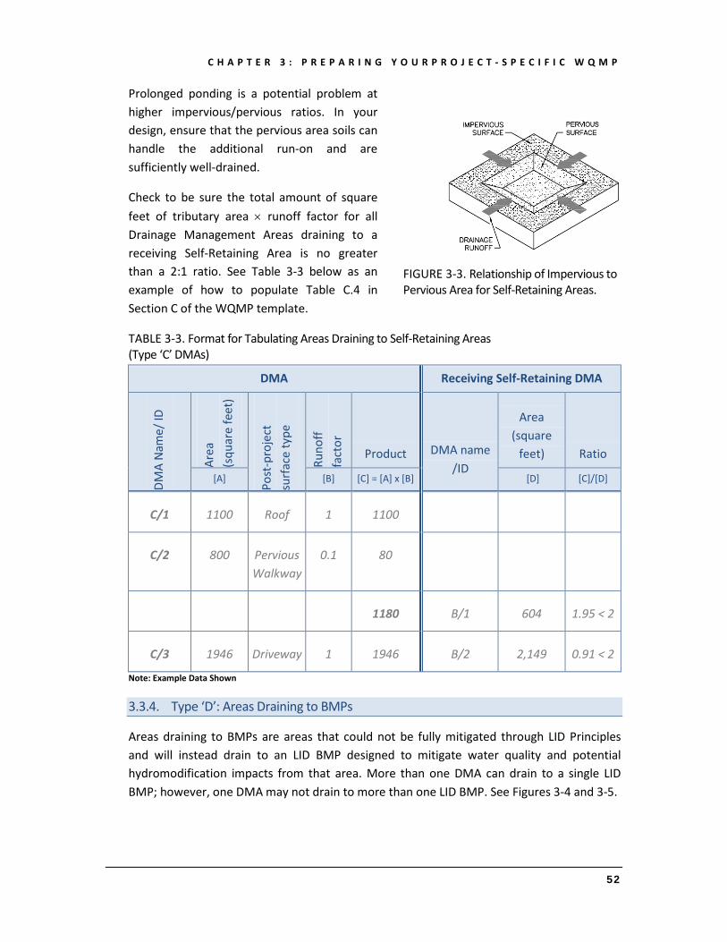
C H A P T E R 3 : P R E P A R I N G Y O U R P R O J E C T - S P E C I F I C W Q M P
52
Prolonged ponding is a potential problem at higher impervious/pervious ratios. In your design, ensure that the pervious area soils can handle the additional run-on and are sufficiently well-drained.
Check to be sure the total amount of square feet of tributary area × runoff factor for all Drainage Management Areas draining to a receiving Self-Retaining Area is no greater than a 2:1 ratio. See Table 3-3 below as an example of how to populate Table C.4 in Section C of the WQMP template.
TABLE 3-3. Format for Tabulating Areas Draining to Self-Retaining Areas (Type ‘C’ DMAs)
DMA Receiving Self-Retaining DMA
DMA
Nam
e/ ID
Area
(s
quar
e fe
et)
Post
-pro
ject
su
rfac
e ty
pe
Runo
ff fa
ctor
Product DMA name /ID
Area (square
feet) Ratio
[A] [B] [C] = [A] x [B] [D] [C]/[D]
C/1 1100 Roof 1 1100
C/2 800 Pervious Walkway
0.1 80
1180 B/1 604 1.95 < 2
C/3 1946 Driveway 1 1946 B/2 2,149 0.91 < 2
Note: Example Data Shown
3.3.4. Type ‘D’: Areas Draining to BMPs
Areas draining to BMPs are areas that could not be fully mitigated through LID Principles and will instead drain to an LID BMP designed to mitigate water quality and potential hydromodification impacts from that area. More than one DMA can drain to a single LID BMP; however, one DMA may not drain to more than one LID BMP. See Figures 3-4 and 3-5.
FIGURE 3-3. Relationship of Impervious to Pervious Area for Self-Retaining Areas.

C H A P T E R 3 : P R E P A R I N G Y O U R P R O J E C T - S P E C I F I C W Q M P
53
Where possible, design site drainage so only impervious roofs and pavement drain to LID BMPs. This yields a simpler, more efficient design, with minimized LID BMP requirements, and also helps protect LID BMPs from becoming clogged by sediment.
If it is necessary to include landscaping, or other pervious surfaces within the area draining to an LID BMP, list each surface as a separate Drainage Management Area. A runoff factor is applied to account for the reduction in the quantity of runoff. Utilize this information to assist you in populating Table C.5 in the WQMP Template.
3.4. IMPLEMENT LID BMPS
3.4.1. LID BMP Selection
Identify the principal constraints on site design and selection of LID BMPs as well as opportunities to reduce imperviousness and incorporate LID Principles into the site and landscape design. For example, constraints might include impermeable soils, high groundwater, groundwater pollution or contaminated soils, steep slopes, geotechnical instability, high-intensity land use, heavy pedestrian or vehicular traffic, utility locations, or safety concerns. Opportunities might include existing natural areas, low areas, oddly configured or otherwise unbuildable parcels, easements and landscape amenities including open space and buffers (which can double as locations for bioretention BMPs), and differences in elevation (which can provide hydraulic head). Reviewing your site utilization and optimization strategies in Section B of the WQMP template will guide you in implementing your LID BMPs.
FIGURE 3-4. More than One DMA can drain to a single LID BMP.
FIGURE 3-5. One DMA cannot drain to more than one LID BMP. Use a grade break to divide the DMA into two DMAs.

C H A P T E R 3 : P R E P A R I N G Y O U R P R O J E C T - S P E C I F I C W Q M P
54
3 . 4 . 1 . a . N a r r a t i v e O v e r v i e w
Review your previously prepared narrative describing site opportunities and constraints with respect to your site optimization. This narrative will help as you proceed with LID design and explain your design decisions to others.
The 2010 SAR MS4 Permit further requires that LID Retention BMPs (Infiltration or Harvest and Use) be used unless it can be shown that those BMPs are infeasible. It is therefore important that your narrative identify and justify if there are any constraints that would prevent the use of those categories of LID BMPs.
3 . 4 . 1 . b . I n f i l t r a t i o n A s s e s s m e n t
LID Infiltration BMPs are to be considered prior to Harvest and Use BMPs. An assessment of the feasibility of utilizing LID Infiltration BMPs is required for all projects, except where there is a ‘Higher and Best Use’ for stormwater runoff (see infiltration discussion in Chapter 2).
If the ‘Highest and Best Use’ criteria do not apply, perform a site-specific evaluation of the feasibility of LID Infiltration BMPs using each of the applicable criteria identified in Chapter 2. If one or more of the infiltration criteria indicate that infiltration is not feasible for the site, the other remaining infiltration criteria do not need to be assessed.
• If any of the groundwater protection requirements identified in Chapter 2 are not met, LID Infiltration BMPs will not be required in those areas. Harvest and Use BMPs must be assessed before Biotreatment BMPs can be used.
• If the geotechnical report identifies areas where infiltration of stormwater would cause public safety risks, such as described in Chapter 2, LID Infiltration BMPs are not required in those areas. Harvest and Use BMPs must be assessed for those areas before Biotreatment BMPs can be used.
• If the evaluation of infiltration characteristics on the site indicate that the minimum infiltration criteria identified in Chapter 2 cannot be met, LID Infiltration BMPs are not required. Harvest and Use BMPs must be assessed for those areas before Biotreatment BMPs can be used.
• If none of the above feasibility criteria indicate that LID Infiltration BMPs are not feasible, LID Infiltration BMPs will be required to the MEP, unless Harvest and Use BMPs are used, before LID Biotreatment can be used.

C H A P T E R 3 : P R E P A R I N G Y O U R P R O J E C T - S P E C I F I C W Q M P
55
3 . 4 . 1 . c . H a r v e s t a n d U s e A s s e s s m e n t
An assessment of the feasibility of implementing Harvesting and Use BMPs is required for all projects, except where reclaimed water will be used for the non-potable water demands for the project, or where downstream water rights may be impacted by Harvest and Use (see Harvest and Use discussion in Chapter 2).
If these criteria do not apply, follow the steps below to assess the Harvest and Use feasibility of Irrigation Use, Toilet Use, and Other non-potable uses (i.e., industrial use).
To perform these assessments, follow these steps:
1. Document these potential demands for the site, as applicable:
a. The total area of irrigated landscape. It will be necessary to determine the type of landscaping that will be implemented on the site. For the purposes of this assessment, landscaping will either be a ‘Conservation Design’ (Low water use, native species, etc), or ‘Active Turf areas’ (higher water use species such as conventional sod). Determine the irrigated landscape area in acres.
b. The expected number of toilet users. This should be based on the average number of daily toilet users during the Wet Season and should account for any periodic shut downs/lapses in occupancy (e.g., for vacations, maintenance, or other reasons).
c. Other non-potable water demands. Identify any other on-site non-potable demand (in gallons per day) that is anticipated on an average daily basis during the Wet Season. Sources of demand should only be included if they are reliably and consistently present during the Wet Season.
2. Identify the planned total of all impervious areas on the proposed project from which runoff might be feasibly captured and stored. Depending on the configuration of buildings and other impervious areas on the site, you may consider the site as a whole, or parts of the site, to evaluate reasonable scenarios for capturing and storing runoff and directing the stored runoff the potential use(s) identified in Step 1 above. Identify the total impervious area in acres.
3. Cross reference the Design Storm depth for the project site (see Exhibit A) with the left column of Tables 2-1 through 2-3 in Chapter 2 to determine, respectively: a) the minimum number of toilet users per tributary impervious acre (TUTIA) and b) the minimum square footage of effective irrigated area per

C H A P T E R 3 : P R E P A R I N G Y O U R P R O J E C T - S P E C I F I C W Q M P
56
tributary impervious acre (EIATIA), and c) the minimum demand for other non-potable uses per tributary impervious acre.
4. Multiply the unit values obtained from Step 3 by the total of impervious areas from Step 2, to develop the minimum demand that would be required for the various forms of Harvest and Use BMPs to be feasible on the project. Then compare minimum demand values to the anticipated demands identified in Step 1.
If any of the anticipated demands exceed the applicable minimum values, Harvest and Use BMPs will be required to be used for applicable DMAs before LID Bioretention can be used. Such DMAs shall be identified as self-retaining. If all of the anticipated demands are less than the applicable minimum values, Harvest and Use BMPs are not required and you should proceed to utilize LID Bioretention and Biotreatment, unless a site specific analysis has been completed that demonstrates technical infeasibility. Consult with your local Co-Permittee prior to eliminating the Bioretention and Biotreatment option(s).

C H A P T E R 3 : P R E P A R I N G Y O U R P R O J E C T - S P E C I F I C W Q M P
57
3.4.2. Types of LID BMPs
Below is a list of types of potential LID BMPs, following the implementation hierarchy as detailed in the 2010 SAR Permit:
1. Infiltration BMPs, which can be used only where soils are highly permeable. Review the assessment of constraints and opportunities to determine the applicability of this LID BMP to the project. Pervious Pavement* can be either pervious asphalt and concrete surfaces, or permeable modular block. Unlike traditional pavements that are impermeable, porous pavements reduce the volume and peak of stormwater runoff as well as mitigate Pollutants from stormwater runoff.
2. Harvest and Use BMPs, which are used to facilitate capturing stormwater runoff for later use. Review the assessment of constraints and opportunities in Chapter 3 to determine the applicability of this LID BMP to the project.
3. Bioretention BMPs, which can be configured as free-form areas, or planters to integrate with your landscape design. Bioretention BMPs are feasible on all soil types and distinguished from Biotreatment BMPs (below) by the fact that their design will process the DCV entirely through a biologically active soil media, and by the fact that they inherently maximize both infiltration and evapotranspiration of runoff. Also see the discussion of LID Retention vs. LID Bioretention in Chapter 2. Bioretention BMPs can be used near building foundations and other locations where infiltration to native soils is not allowed by incorporation of an impermeable liner.
4. Biotreatment BMPs, which can be used only where soils are relatively impermeable (measured KSAT < 0.3"/hr.) These BMPs are distinguished from bioretention BMPs in that they do not process the entire DCV through a soil media. However, they still provide similar functions and benefits to bioretention BMPs by incorporation of features that provide for natural biological processes while maximizing opportunities for infiltration and evapotranspiration. Examples of Biotreatment BMPs include extended detention basins, bioswales and constructed wetlands. Consult your Co-Permittee to determine approved Biotreatment BMPs.
* When pervious pavement is designed primarily as a site design feature (i.e. it doesn’t receive runoff from more than 2 parts tributary impervious area to 1 part pervious pavement), the pervious pavement is considered a self-retaining area. If additional area is drained onto the pervious pavement beyond the 2:1 ratio, the pervious pavement will be required to be constructed in accordance with a Co-Permittee approved stormwater BMP design that allows for greater ratios, (such as the LID BMP Design Handbook). In this case, pervious pavement is considered a LID BMP.

C H A P T E R 3 : P R E P A R I N G Y O U R P R O J E C T - S P E C I F I C W Q M P
58
Descriptions, illustrations, designs and design criteria for the LID BMPs described herein can be found in the LID BMP Design Handbook. The Co-Permittees may have their own designs for these same BMPs, or may specify other BMPs that applicants may use.
Review the constraints and opportunities and select from the applicable BMPs presented in Table 3-4. See the notes in the table regarding requirements as well as Figure 3-6 for BMP selection guidance.
FIGURE 3-6. LID BMP Feasibility Flow Chart
The BMP feasibility analysis must be performed on a DMA by DMA basis.

C H A P T E R 3 : P R E P A R I N G Y O U R P R O J E C T - S P E C I F I C W Q M P
59
TABLE 3-4. LID BMP Applicability
LID BMP Hierarchy
A B C D
KSAT> 1.6"/hr., and no
restrictions on infiltration
Are Harvest and Use
BMPs feasible?
0.3"/hr. < KSAT < 1.6"/hr.,
or unpredictable or unknown
KSAT < 0.3"/hr.
LID Infiltration BMPs*
Harvest and Use BMPs
LID Bioretention
LID Biotreatment
Notes for Table 3-5: See also Figure 3-6 for guidance in selecting appropriate BMPs Column A: Selections from this column may be used in locations where the infiltration rate of underlying soils is at least 1.6" per hour and no restrictions on infiltration apply to these locations. Column B: Harvest and Use BMPs may be used where it can be shown that there is sufficient demand for harvested water and where LID Infiltration BMPs are not feasible.
Column C: Selections in this column may be used in locations where the measured infiltration rate of underlying soils is between 0.3" and 1.6" per hour or where, in accordance with recommendations of a licensed geotechnical engineer, the post-development saturated hydraulic conductivity is uncertain or unknown or cannot be reliably predicted because of soil disturbance or fill, anisotropic soil characteristics, presence of clay lenses, or other factors. Column D: Selections in this column may be used in locations where the infiltration rate of underlying soils is 0.3" per hour or less. See Chapter 2 for more information. * Permeable Pavement, when designed with a maximum of a 2:1 ratio of impervious area to pervious pavement areas, or less, is considered a self-retaining area, and is not considered an LID BMP for the purposes of this table. This table focuses on the ‘special case’ included in the discussion of ‘areas draining to self-retaining areas’ above, where a project proponent can choose to design the pervious pavement as a LID BMP in accordance with an approved design, such as the LID BMP Design handbook, and in return drain additional impervious area onto the pervious pavement beyond the 2:1 ratio.
3 . 4 . 2 . a . L a y i n g o u t y o u r L I D B M P s
Finding the right location for LID BMPs on your site involves a careful and creative integration of several factors:
To make the most efficient use of the site and to maximize aesthetic value, integrate BMPs with site landscaping. Many local zoning codes may require landscape setbacks or buffers, or may specify that a minimum portion of the site be landscaped. It may be possible to locate some or all of your site’s Stormwater BMPs within this same area, or within utility easements or other non-buildable areas.
Bioretention BMPs must be level or nearly level all the way around. When configured in a linear fashion (similar to swales) bioretention BMPs may be gently sloped end to end, but opposite sides must be at the same

C H A P T E R 3 : P R E P A R I N G Y O U R P R O J E C T - S P E C I F I C W Q M P
60
elevation. BMPs on steeper slopes must be terraced or provided with check dams.
For effective, low-maintenance operation, locate LID BMPs so drainage into and out of the device is by gravity flow. Most LID BMPs require 3 feet or more of head.
LID BMPs require excavations 3 or more feet deep, which can conflict with underground utilities.
If the property is being subdivided now or in the future, the facility should be in a common, accessible area. In particular, avoid locating LID BMPs on private residential lots. Even if the LID BMP facility will serve only one site owner or operator, make sure the facility is located for ready access by inspectors from the local Co-Permittee and the local mosquito and vector control agency. The goal is to ensure that LID BMPs are maintained and functional, to assure a properly functioning maintenance mechanism since the ability of individual homeowners to provide maintenance is variable, and to avoid residential property rights issues for inspections and verifications. While the specific maintenance mechanism will be provided on a project by project basis, many Co-Permittees are pursuing methods to allow residential LID BMPs to be maintained by a public entity. Maintenance via a public maintenance mechanism will require BMPs to be located in common areas and not in individual lots.
The LID BMP facility must be accessible to equipment needed for its maintenance. Access requirements for maintenance will vary with the type of facility selected. Bioretention BMPs will typically need access for the same types of equipment used for landscape maintenance.
To complete your analysis, include in your Project-Specific WQMP a brief narrative documenting the site layout and site design decisions you made. This will provide background and context for how your design meets the quantitative LID BMP design criteria. Once you have laid out the LID BMPs, calculate the square footage you have set aside on your site plan for each BMP.
3.4.3. Calculate Minimum LID BMP Sizes
LID BMPs must be sized to address the DCV. For Bioretention BMPs, some simplifying geometric assumptions have been established for sizing these BMPs, and sizing factors have been established pursuant to the LID BMP Design Handbook. For other LID BMPs, a BMP-specific design must be performed to ensure that the DCV will be addressed. The LID BMP Design Handbook contains sizing worksheets for many types of LID BMPs, however, project
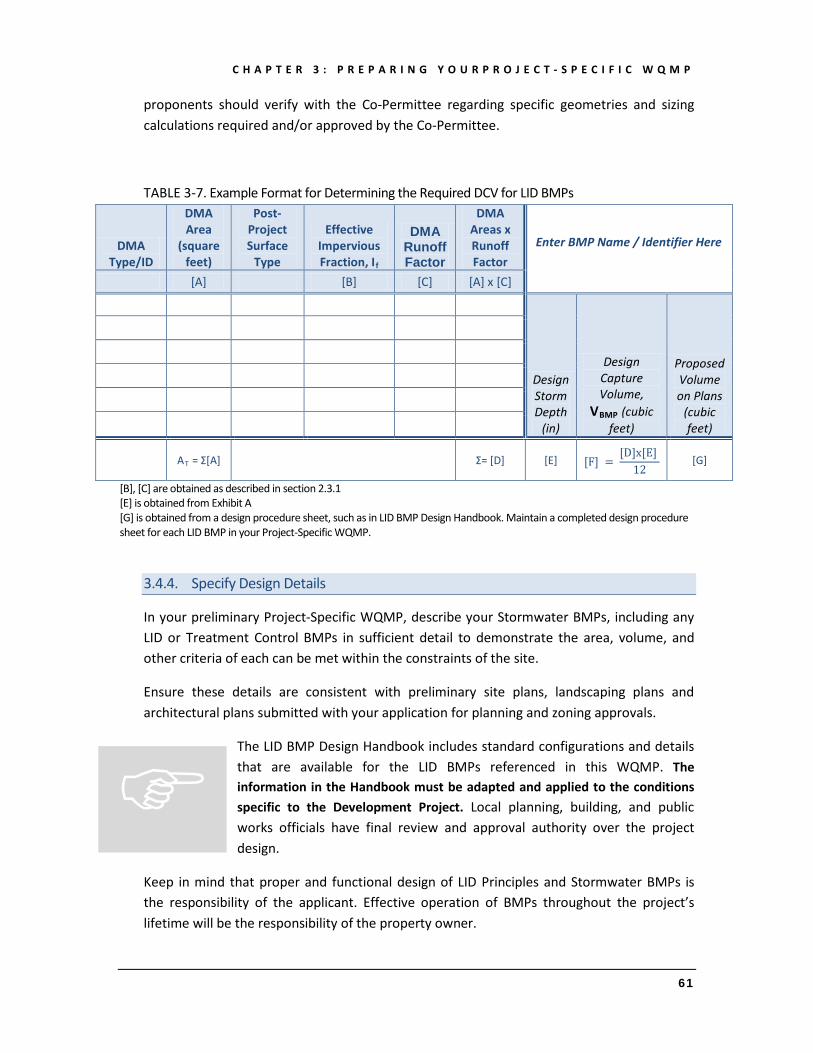
C H A P T E R 3 : P R E P A R I N G Y O U R P R O J E C T - S P E C I F I C W Q M P
61
proponents should verify with the Co-Permittee regarding specific geometries and sizing calculations required and/or approved by the Co-Permittee.
TABLE 3-7. Example Format for Determining the Required DCV for LID BMPs
DMA Type/ID
DMA Area
(square feet)
Post-Project Surface
Type
Effective Impervious Fraction, If
DMA Runoff Factor
DMA Areas x Runoff Factor
Enter BMP Name / Identifier Here
[A] [B] [C] [A] x [C]
Design Storm Depth
(in)
Design Capture Volume,
VBMP (cubic feet)
Proposed Volume on Plans
(cubic feet)
AT = Σ[A]
Σ= [D] [E] [F] =
[D]x[E] 12 [G]
[B], [C] are obtained as described in section 2.3.1 [E] is obtained from Exhibit A [G] is obtained from a design procedure sheet, such as in LID BMP Design Handbook. Maintain a completed design procedure sheet for each LID BMP in your Project-Specific WQMP.
3.4.4. Specify Design Details
In your preliminary Project-Specific WQMP, describe your Stormwater BMPs, including any LID or Treatment Control BMPs in sufficient detail to demonstrate the area, volume, and other criteria of each can be met within the constraints of the site.
Ensure these details are consistent with preliminary site plans, landscaping plans and architectural plans submitted with your application for planning and zoning approvals.
The LID BMP Design Handbook includes standard configurations and details that are available for the LID BMPs referenced in this WQMP. The information in the Handbook must be adapted and applied to the conditions specific to the Development Project. Local planning, building, and public works officials have final review and approval authority over the project design.
Keep in mind that proper and functional design of LID Principles and Stormwater BMPs is the responsibility of the applicant. Effective operation of BMPs throughout the project’s lifetime will be the responsibility of the property owner.

C H A P T E R 3 : P R E P A R I N G Y O U R P R O J E C T - S P E C I F I C W Q M P
62
References and Resources Pitt, R.E. and Maestre, A. 2005. Stormwater quality as described in the National
Stormwater Quality Database (NSQD). 10th International Conference on Urban Drainage. Copenhagen, Denmark. August 2005.
Stein, E.D., Tiefenthaler, L.L. and Schiff, K.C. 2007. Stormwater Sources, Patterns and Mechanisms of Stormwater Pollutant Loading from Watersheds and Land Uses of the Greater Los Angeles Area, California, USA. Southern California Coastal Water Research Project. Technical Report 510. March 2007.
3.4.5. Determine if Size is Adequate
Sizing and configuring BMPs is typically an iterative process. After computing the minimum BMP area as detailed above, review the site plan to determine if the reserved BMP areas are sufficient for all of Type ‘D’ Drainage Management Areas – “Areas Draining to BMPs.”
If so, the planned BMPs will meet the WQMP sizing requirements for water quality.
If not, revise the plan accordingly. Revisions may include:
• Reducing the overall imperviousness of the project site.
• Changing the grading and drainage to redirect some runoff toward other BMPs which may have excess capacity.
• Making tributary landscaped Drainage Management Areas self-treating or self-retaining (may require changes to grading).
• Expanding BMP surface area.
Note: Revisions to square footage of a BMP typically require a corresponding revision to the square footage of the surrounding or adjacent DMA.

C H A P T E R 3 : P R E P A R I N G Y O U R P R O J E C T - S P E C I F I C W Q M P
63
3.5. ALTERNATIVE COMPLIANCE
As discussed in Chapter 2, LID BMPs are expected to be feasible on virtually all projects. Where LID BMPs have been demonstrated to be infeasible consistent with the criteria defined in Chapter 2, other Treatment Control BMPs must be used to achieve the same level of compliance.
3.5.1. Stormwater Credits
MS4 Permit Section XII.G.4 allows for the Co-Permittees to establish, where feasible and practicable, a water quality credit system for alternatives to infiltration, harvesting and use, Evapotranspiration, and other LID and Hydromodification requirements specified above.
For certain types of Development Projects, LID BMPs may be more difficult to incorporate due to the nature of the development, but the development practices may provide other environmental benefits to communities. For example, Infiltration BMPs may not be allowed on a Brownfield Redevelopment Project site where infiltrated stormwater could cause an adverse impact to groundwater supply, but redevelopment of the site would be expected to have other environmental benefits such as accelerated site clean-up. Alternatively, a Redevelopment Project could be implemented in a way that reduces the overall impervious footprint of the project site rather than increasing it.
Projects potentially eligible for consideration for water quality credits include:
• Redevelopment Projects that reduce the overall impervious footprint of the project site.
• Brownfield redevelopment, meaning redevelopment, expansion, or reuse of real property which may be complicated by the presence or potential presence of hazardous substances, Pollutants or contaminants, and which have the potential to contribute to adverse ground or surface water quality if not redeveloped (http://www.epa.gov/brownfields/overview/glossary.htm).
• Higher density Development Projects which include two distinct categories (credits can only be taken for one category):
o Those with more than seven units per acre of development (lower credit allowance).
o Vertical density developments, for example, those with a Floor to Area Ratio (FAR) of 2, or those having more than 18 units per acre (greater credit allowance).

C H A P T E R 3 : P R E P A R I N G Y O U R P R O J E C T - S P E C I F I C W Q M P
64
• Mixed use development, such as a combination of residential, commercial, industrial, office, institutional, or other land uses which incorporate design principles that can demonstrate environmental benefits that would not be realized through single use projects (e.g., reduced vehicle trip traffic with the potential to reduce sources of water or air pollution).
• Transit-oriented developments, such as a mixed use residential or commercial area designed to maximize access to public transportation; similar to above criterion, but where the development center is within one half mile of a mass transit center (e.g., bus, rail, light rail or commuter train station). Such projects would not be able to take credit for both categories, but may have greater credit assigned.
• Developments with dedication of undeveloped portions to parks, preservation areas and other pervious uses.
• Regional treatment systems with a capacity to treat flows from all upstream developments.
• Offsite mitigation or dedicated mitigation areas within the same watershed.
• Developments in highly urbanized areas such as a city center area.
• Developments in historic districts or historic preservation areas.
• Live-work developments, a variety of developments designed to support residential and vocational needs together – similar to criteria to mixed use development; would not be able to take credit for both categories.
• In-fill projects, the conversion of empty lots and other underused spaces into more beneficially used spaces, such as residential or commercial areas, as defined by the local jurisdiction.
This provision does not exempt the project proponent from first conducting the investigations to determine if it is feasible to fulfill the full LID requirements through a combination of LID Principles and LID BMPs consistent with the 2010 SAR MS4 Permit hierarchy.

C H A P T E R 3 : P R E P A R I N G Y O U R P R O J E C T - S P E C I F I C W Q M P
65
Applying Water Quality Credits To determine the amount of credit a project would qualify for, the first step is to calculate the DCV that would need to be satisfied in the absence of any credits. Any credits would then be taken as a reduction to this remaining volume. For all categories of projects noted above, the remaining volume to be treated or mitigated would be reduced in accordance with portions of the DCV shown in Table 3-8.
TABLE 3-8. Water Quality Credits for Applicable Project Categories
Project Category Water Quality Credit
(% of DCV) 1 Redevelopment Projects that reduce the overall impervious footprint of the project site
Percentage of site imperviousness reduced
Historic district, historic preservation area, or similar areas 10%
Brownfield redevelopment 25%
Higher density development, 7 units/acre or more 5%
Higher density development, vertical density 20%
Mixed use development, transit oriented development or live-work development 20%
In-fill development 10% 1 Maximum total of water quality credits for a project is 50%
If more than one category applies to a particular project, the credit percentages would be additive. Applicable performance criteria depend on the number of LID water quality credits claimed by the proposed project. Water quality credits can be additive up to a 50 percent reduction (50 percent reduction maximum) from a proposed project’s obligation for sizing Treatment Control BMPs, contributing to an urban runoff/mitigation fund, or off-site mitigation projects. The volume credit would be calculated as the DCV of the proposed condition multiplied by the sum of the percentages claimed above.
3.5.2. Treatment Control BMPs
Treatment Control BMPs provide treatment mechanisms for pollutants in runoff, but do not sustain significant biological processes. Treatment Control BMPs must be selected to treat Pollutants of Concern with a high or medium effectiveness. Additionally, Treatment Control BMPs must not be constructed within Receiving Waters.
Pollutants of Concern
Identifying the Pollutants of Concern for the selection of Treatment Control BMPs involves:

C H A P T E R 3 : P R E P A R I N G Y O U R P R O J E C T - S P E C I F I C W Q M P
66
• Identifying all downstream Receiving Waters to the discharge point(s) of the project that are listed in the most recent version of the Water Quality Control Plan for the Santa Ana River Basin http://waterboards.ca.gov/santaana/water_issues/program/basin_plan/.
• Reviewing the 303(d) listings for all downstream Receiving Waters http://waterboards.ca.gov/santaana/water_issues/programs/tmdl/303d.shtml and identifying any pollutants being addressed by an adopted TMDL http://waterboards.ca.gov/santaana/water_issues/programs/tmdl/.
• Reviewing the potential Pollutants generated by the project, using information such as, but not limited to Table 3-9 below, and identify those pollutants that are also on the 303(d) list or have adopted TMDLs. Pollutants that are listed on Table 3-9 for the development type, and also are on the 303(d) list or have adopted TMDLs, are considered Pollutants of Concern. Table 3-9 may be updated by the Co-Permittees periodically based on updated studies and information. Updates will be reported in the applicable Annual Report to the Santa Ana Regional Board.
TABLE 3-9. Potential Pollutants Generated by Land Use Type Priority Development
Project Categories and/or Project Features
General Pollutant Categories Bacterial
Indicators Metals Nutrients Pesticides Toxic Organic
Compounds Sediments Trash & Debris Oil & Grease
Detached Residential Development P N P P N P P P
Attached Residential Development P N P P N P P P(2)
Commercial/Industrial Development P(3) P P(1) P(1) P(5) P(1) P P
Automotive Repair Shops N P N N P(4, 5) N P P
Restaurants (>5,000 ft2) P N N N N N P P
Hillside Development (>5,000 ft2) P N P P N P P P
Parking Lots (>5,000 ft2) P(6) P P(1) P(1) P(4) P(1) P P
Retail Gasoline Outlets N P N N P N P P P = Potential N = Not Potential (1) A potential Pollutant if non-native landscaping exists or is proposed on-site; otherwise not expected. (2) A potential Pollutant if the project includes uncovered parking areas; otherwise not expected (3) A potentialPpollutant is land use involves animal waste
(4) Specifically petroleum hydrocarbons (5) Specifically solvents (6) Bacterial indicators are routinely detected in pavement runoff

C H A P T E R 3 : P R E P A R I N G Y O U R P R O J E C T - S P E C I F I C W Q M P
67
Selection and Sizing
Treatment Control BMPs must be selected that have a high or medium effectiveness at treating the Pollutants of Concern. For Treatment Control BMPs identified in a Co-Permittee approved design manual, the effectiveness identified for those particular BMP designs can be referenced. For other Treatment Control BMPs, high or medium effectiveness designation must be substantiated by independent third-party ‘in-situ’ testing of the specific Treatment Control BMPs being considered, such as provided on the references included in the BMP Performance Report Library, located at:
http://rcflood.org/NPDES/BMPPerformance.aspx
There are two design sizing standards for conventional Treatment Control BMPs. Depending on their design, they will be either Volume-Based or Flow-Based, and sized to the DCV, or the Design Flow Rate, respectively. These methodologies are discussed further in Chapter 2. Treatment Control BMPs must be sized to treat any unmet volume after claiming applicable water quality credits, if available. Document in your WQMP Template that all ‘areas draining to BMPs’ have been fully addressed either using LID, or Treatment Control BMPs using the table below.
TABLE 3-10. Format for Presenting Calculations for Treatment Control BMPs
DMA Type/ID
DMA Area
(square feet)
Post-Project Surface Type
Effective Impervious Fraction, If
DMA Runoff Factor
DMA Area x Runoff Factor
Enter BMP Name / Identifier Here
[A] [B] [C] [A] x [C]
Design Storm Depth
(in)
Minimum Design
Capture Volume or
Design Flow Rate (cubic feet or cfs)
Proposed Volume or Flow on Plans
(cubic feet or
cfs)
AT = Σ[A]
Σ= [D] [E] [F] =
[D]x[E] [G] [H]
[B], [C] are obtained as described in section 2.3.1 [E] is obtained from Exhibit A [G] for Flow-Based Treatment Control BMPs [G] = 43,560, for Volume-Based Control Treatment BMPs, [G] = 12 [H] is obtained from a design procedure sheet from the BMP manufacturer
Once any applicable Drainage Management Areas have been fully addressed using Treatment Control BMPs in accordance with the above requirements, continue to Section 3.6.

C H A P T E R 3 : P R E P A R I N G Y O U R P R O J E C T - S P E C I F I C W Q M P
68
3.5.3. Waivers
If the site-specific determination demonstrates that the cost of BMP implementation greatly outweighs the pollution control benefits, the Co-Permittee may grant a waiver of the BMPs. All waivers, along with waiver justification documentation, will be submitted to the RWQCB Executive Officer for approval in writing within 30 days prior to approval by the Co-Permittee.
All projects receiving such an approved waiver will be required to participate in an Alternative or In-Lieu program developed or approved by the Co-Permittee, such as a fund for water quality improvement projects, or a water quality credit system. Note that such funds or systems may or may not be available for specific Co-Permittees or for specific projects, and in such cases, waivers may not be allowed.
3.5.4. Urban Runoff Fund
MS4 Permit Section XII.G.2 allows for the Co-Permittees to, collectively or individually, propose to establish an Urban Runoff fund to be used for urban water quality improvement projects within the same watershed that is funded by contributions from developers granted waivers. At this time, such a program has not been developed. If such programs are developed in the future, they will be incorporated into a revised WQMP.
3.6. HYDROMODIFICATION
Once you have determined that the LID design is adequate to address the treatment requirements, you will need to assess if the proposed LID Design may still create an HCOC. Review the criteria identified in Chapter 2.
Figure 3-7 shows the process for ensuring compliance with HCOC requirements.
To determine if the proposed project creates an HCOC, the project engineer must compute pre and post development hydrology for a 24-hour Design Storm event with a 2-year return period. Acceptable methodologies for performing this hydrologic analysis include:
• Riverside County Hydrology Manual
• Technical Release 55 (TR-55): Urban Hydrology for Small Watersheds (NRCS 1986) or derivatives thereof such as the Santa Barbara Urban Hydrograph Method.
• Other methods acceptable to the Co-Permittee
Where the hydrologic analysis confirms an HCOC exists, you may need to reassess the LID design and revise as needed to mitigate any potential Hydromodification effects.

C H A P T E R 3 : P R E P A R I N G Y O U R P R O J E C T - S P E C I F I C W Q M P
69
FIGURE 3-7. Hydromodification Criteria for the Santa Ana Region

C H A P T E R 3 : P R E P A R I N G Y O U R P R O J E C T - S P E C I F I C W Q M P
70
3.7. SPECIFY SOURCE CONTROL BMPS
Some everyday activities – such as trash recycling/disposal and washing vehicles and equipment – can generate pollutants that tend to find their way into storm drains. These pollutants can be minimized by applying source control BMPs. Source control BMPs include permanent, structural features that may be required in your project plans—such as roofs over and berms around trash and recycling areas—and Operational BMPs, such as regular sweeping and “housekeeping,” that must be implemented by the site’s occupant or user. The MEP standard typically requires both types of BMPs. In general, Operational BMPs cannot be substituted for a feasible and effective permanent BMP. Follow the procedure as enumerated in Section G of the WQMP template to help you document your Source Control BMP analysis and selection.
References and Resources Appendix 8, WQMP Template, Stormwater Pollutant Sources/Source Control Checklist California Stormwater Industrial/Commercial Best Management Practice Handbook Urban Runoff Quality Management (WEF/ASCE, 1998) Chapter 4: Source Controls
3.8. COORDINATION OF WQMP DESIGN
Follow the guidance in Section 4 to ensure that your Project-Specific WQMP, including all LID Principles, LID BMPs, Alternative Compliance measures, Hydromodification BMPs, and Source Control BMPs, are properly identified on and coordinated with all other site plans, such as Architectural, Improvement, Construction and Landscaping Plans.
3.9. DEVELOP AN O&M PLAN
As required by 2010 SAR MS4 Permit Provision XII.K, the Co-Permittee will periodically verify that Stormwater BMPs on your site are maintained and continue to operate as designed.
To make this possible, your Co-Permittee will require that you include in your Project-Specific WQMP:
1. A means to finance and implement facility maintenance in perpetuity.
2. Acceptance of responsibility for maintenance from the time the BMPs are constructed until responsibility for operation and maintenance is legally transferred. A warranty covering a period following construction may also be required.
3. An outline of general maintenance requirements for the Stormwater BMPs you have selected.
Your local Co-Permittee will also require that you prepare and submit a detailed Stormwater BMP Operation and Maintenance Plan that sets forth a maintenance schedule for each of the Stormwater BMPs built on your site. An agreement assigning responsibility for maintenance and

C H A P T E R 3 : P R E P A R I N G Y O U R P R O J E C T - S P E C I F I C W Q M P
71
providing for inspections and certification may also be required. Details of these requirements, and instructions for preparing a Stormwater BMP Operation and Maintenance Plan, are in Chapter 4.
References and Resources Chapter 5 Operation, Maintenance, and Management of Stormwater Management Systems
(Watershed Management Institute, 1997)

W A T E R Q U A L I T Y M A N A G E M E N T P L A N F O R T H E S A N T A A N A R E G I O N O F R I V E R S I D E C O U N T Y
72
4.0 COORDINATION WITH OTHER SITE PLANS
Your Project-Specific WQMP should document the information gathered and decisions made in Chapter 3. Submittal of a clear, complete, well-organized WQMP will make it possible for agency staff reviewers to confirm your design meets minimum requirements.
4.1. COORDINATION WITH SITE, ARCHITECTURAL, AND LANDSCAPING PLANS
Before completing your Project-Specific WQMP exhibit and report, ensure your stormwater control design is fully coordinated with the site plan, grading plan and landscaping plan being proposed for the site.
Information and presentations submitted to design review committees, planning commissions and other decision-making bodies must incorporate relevant aspects of the stormwater design. In particular, ensure:
• Curb elevations, elevations, grade breaks, and other features of the drainage design are consistent with the delineation of Drainage Management Areas.
• The top edge (overflow) of each bioretention facility is level all around its perimeter—this is particularly important in parking lot medians.
• The resulting grading and drainage design is consistent with the design for parking and circulation.
Chapter
4 I C O N K E Y
Helpful Tip
Submittal Requirement
Terms to Look Up
References & Resources

C H A P T E R 4 : C O O R D I N A T I O N W I T H O T H E R S I T E P L A N S
73
• Bioretention BMPs and other BMPs do not create conflicts with pedestrian access between parking and building entrances.
• Vaults and utility boxes will be accommodated outside of BMPs and will not be placed within BMPs in a manner that interferes with their maintenance and operation.
• The visual impact of Stormwater BMPs, including Bioretention BMPs at building foundations and any terracing or retaining walls required for the stormwater control design, will be shown in renderings and other architectural drawings.
• Landscaping plans, including planting plans, show locations of BMPs, and the plant requirements consistent with the engineered soils and conditions in the BMPs. For more information, see Appendix A of the Low Impact Development Manual for Southern California (http://www.casqa.org/LinkClick.aspx?fileticket=zhEf2cj4Q%2fw%3d&tabid=218).
• Renderings and representation of street views incorporate any Stormwater BMPs located in street-side buffers and setbacks.
• Any potential conflicts with local development standards have been identified and resolved.
• Review Section 4.5, Structural BMP Construction, to anticipate additional requirements for construction of BMPs.
4.2. CERTIFICATION
The Project-Specific WQMP must include the following certification language: “The selection, sizing, and preliminary design of stormwater treatment and other control measures in this plan meet the requirements of Regional Water Quality Control Board Order R8-2010-0033 and any subsequent amendments.” The Co-Permittee may require that your Project-Specific WQMP be certified by a licensed civil engineer.
4.3. CONSTRUCTION PLAN WQMP CHECKLIST
When you submit construction plans for Co-Permittee review and approval, the plan checker will compare that submittal with your Project-Specific WQMP. To facilitate the plan checker’s comparison and speed review of your project, utilize the table and instructions in the WQMP template Section H to create a Construction WQMP Checklist for your project. See Section 4.5 for details of construction information that should be included in your construction plans.

C H A P T E R 4 : C O O R D I N A T I O N W I T H O T H E R S I T E P L A N S
74
4.4. PREPARE AN OPERATIONS AND MAINTENANCE PLAN
Follow the guidance in Chapter 5 to develop a Stormwater BMP Operations and Maintenance Plan. This O&M Plan will be included in Appendix 9 in your Project Specific WQMP.
4.5. STRUCTURAL BMP CONSTRUCTION
Details of how Stormwater BMPs are constructed can be critical to ensuring they work properly. A misplaced inlet, an overflow at the wrong elevation, or the wrong soil mix can make an LID BMP ineffective even before it comes on-line, and could result in delays to project approvals and additional expense.
Your Project-Specific WQMP must contain enough detail to demonstrate your planned LID Principles and Stormwater BMPs are feasible and are coordinated with the project site plan, architectural renderings, landscape design, and other information submitted with your application for development approvals. Additional detail as described in this section, must be shown on plans submitted with applications for building and grading permits. During construction and at completion, Co-Permittee inspectors will check the work against the approved plans.
The LID BMP Design Handbook includes details, many of which are critical to proper functioning of the BMP. This chapter describes specific items to be checked during review of construction documents and during construction.
LID Principles and LID BMPs have been routinely incorporated into Development Projects for only a few years. The community of land development professionals and Co-Permittee staff continue to compile and analyze “lessons learned” from their experience. The following guidance is based on those lessons.
4.5.1. What to Show on Construction Plans
With few exceptions, the plan set should include separate sheets specifically incorporating the Stormwater BMPs described in the Project-Specific WQMP. The information on these sheets must be carefully coordinated and made consistent with grading plans, utility plans, landscaping plans, and (in many cases) architectural plans. Consider including the grading plan
(screened) as background for the stormwater sheets. It may also be appropriate to show portions of the roofing plan wherever roof ridges define Drainage Management Areas. Additionally, utilizing different colors with associated legends will help reviewers differentiate the different details shown on the construction plans with respect to grading and runoff management.
Design Note Use surface drainage, such as
valley gutters or trench drains, to keep drainage within a few inches below top of pavement. Or use a
“bubble up” to bring drainage back up closer to the surface.

C H A P T E R 4 : C O O R D I N A T I O N W I T H O T H E R S I T E P L A N S
75
4 . 5 . 1 . a . G r a d i n g i s K e y
Co-Permittee staff will typically require plans showing the outline of each bioretention facility or other Treatment Control BMP, along with the delineation of Drainage Management Areas. Call out elevations, including the following:
• At curb cut inlets, show elevations for top of paving, top of curb and top of the bioretention soil layer.
• At overflow grates, show the grate elevation and the adjacent top of soil elevation.
• Call out elevations of piped inlets.
Show how Drainage Management Areas follow grade breaks, consistent with the grading plan and the Project-Specific WQMP.
4 . 5 . 1 . b . S h o w H o w R u n o f f M o v e s
As needed for clarity, show the direction of runoff flow across roofs and pavement and into Treatment Control BMPs. For runoff conveyed via pipes or channels, show locations, slopes, and elevations at the beginning and end of each run.
For roof drainage, show the routing of roof leaders. Use drawings or notes to make clear how drainage from leaders is routed under walkways, across pavement, through drainage pipes, or by other means to reach the BMP.
Show pipes or channels connecting the BMP underdrain and overflow to the site drainage system, MS4, or other approved discharge point. Call out slopes and key elevations.
4 . 5 . 1 . c . S h o w B M P s i n C r o s s - S e c t i o n
Use one or more cross-section drawings to illustrate details and key BMP elevations, including bottom of excavation, top of gravel layer, top of soil layer, edge treatments, inlet elevations, overflow grate elevations, rim elevations, locations of rock for energy dissipation, moisture barriers, and other information. Call out specifications or refer to specifications elsewhere for gravel (Class 2 perm) and soil mix.
4.5.2. Items to Be Inspected During Construction
Successful construction of BMPs requires attention to detail during every stage of the construction process, from initial layout to rough grading, installation of utilities, construction of buildings, paving, landscaping, and final clean-up and inspection.

C H A P T E R 4 : C O O R D I N A T I O N W I T H O T H E R S I T E P L A N S
76
Construction project managers need to understand the purpose and function of BMPs and know how to avoid common missteps that can occur during construction. For LID BMPs, the following operating principles should be noted at a pre-construction meeting.
• Runoff flow from the intended tributary Drainage Management Area must flow into the facility.
• The surface reservoir must fill to its intended volume during high inflows.
• Runoff must filter rapidly through the filtration/soil layer.
• Filtered runoff must infiltrate into the native soil to the extent feasible (or allowable).
• Remaining runoff must be captured and drained to a MS4 facility or other approved location.
See the model construction inspection checklist included in Exhibit G for assistance with construction of BMP.

W A T E R Q U A L I T Y M A N A G E M E N T P L A N F O R T H E S A N T A A N A R E G I O N O F R I V E R S I D E C O U N T Y
77
5.0 OPERATION & MAINTENANCE OF STORMWATER BMPS
How to prepare a customized Stormwater BMP Operation & Maintenance Plan for the BMPs on your site.
Stormwater NPDES Permit Provision XII.K.5 requires that each Co-Permittee verify Stormwater BMPs are adequately maintained. Co-Permittees must report the results of inspections to the Water Board annually.
Stormwater BMPs you install as part of your project will be incorporated into the Co-Permittee’s verification program. This is a six-stage process:
1. Determine who will own the Stormwater BMP facility and be responsible for its maintenance in perpetuity and document this in your Project-Specific WQMP. The Project-Specific WQMP must also identify the means by which ongoing maintenance will be assured (for example, a maintenance agreement that runs with the land). Appropriate documentation regarding BMP recordation should be provided.
2. Identify typical maintenance requirements, allow for these requirements in your project planning and preliminary design, and document the typical maintenance requirements in your Project-Specific WQMP.
3. Prepare an Operation and Maintenance Plan (O&M Plan) for the site incorporating detailed requirements for each Treatment Control BMP and flow-control facility. Other types of LID BMPs may also require operation and maintenance. Typically, a draft O&M Plan must be submitted with the building permit application, and a final O&M Plan must be submitted for review and approved by the Co-Permittee prior to building permit final and issuance of a certificate of occupancy. Local requirements vary as to schedule. Check with Co-Permittee staff.
Chapter
5
I C O N K E Y
Helpful Tip
Submittal Requirement
Terms to Look Up
References & Resources

C H A P T E R 6 : O & M O F S T O R M W A T E R B M P S
78
4. Maintain the BMPs from the time they are constructed until ownership and maintenance responsibility are formally transferred.
5. Formally transfer operation and maintenance responsibility to the site owner or occupant. A warranty, secured by a bond or other financial instrument, may be required to secure against lack of performance due to flaws in design or construction. A typical warranty period will cover two rainy seasons. All Structural BMPs described in the Project-Specific WQMP shall be constructed and installed in conformance with approved plans and specifications. It shall be demonstrated that the applicant is prepared to implement all Non-Structural BMPs described in the approved Project-Specific WQMP and that copies of the approved Project-Specific WQMP are available for the future owners/occupants. The Riverside County Flood Control and Water Conservation District will not release occupancy permits for any portion of the project exceeding 80 percent of the total recorded residential lots within the map or phase within the map prior to the completion of these tasks.
6. Maintain the BMPs in perpetuity and comply with your Co-Permittee’s self-inspection, reporting and verification requirements.
See the schedule for these stages in Table 5-1. Again, local requirements will vary.
TABLE 5-1. Schedule for Planning Operation and Maintenance of Stormwater BMPs Stage Description Where documented Schedule
1 Determine facility ownership and maintenance responsibility
Preliminary Project-Specific WQMP
Discuss with planning staff at pre-application meeting
2 Identify typical maintenance requirements
Preliminary Project-Specific WQMP
Submit with planning and zoning application
3 Develop detailed operation and maintenance plan
Final Project-Specific WQMP
Submit draft with Building Permit application; final due before building permit final and applying for a Certificate of Occupancy
4 Interim operation and maintenance of BMPs
As required by Co-Permittee O&M verification program
During and following construction including warranty period
5 Formal transfer of operation and maintenance responsibility
As required by Co-Permittee O&M verification program
On sale and transfer of property or occupancy
6 Ongoing maintenance and compliance with inspection and reporting requirements
As required by Co-Permittee O&M verification program
In perpetuity

C H A P T E R 6 : O & M O F S T O R M W A T E R B M P S
79
5.1. STAGE 1: OWNERSHIP AND MAINTENANCE RESPONSIBILITY
Your Project-Specific WQMP must specify a means to finance maintenance of Stormwater BMPs in perpetuity once the Stormwater BMP is implemented and the project is complete.
Depending on the intended use of your site and the policies of the local Co-Permittee, this may require one or more of the following:
• Execution of a maintenance agreement that “runs with the land.”
• Creation of a homeowners’ association (HOA), Property Owners’ Association (POA) and execution and recordation of a Condition, Covenant, and Restriction (CC&R) that clearly stipulates the maintenance responsibilities.
• Formation of a new community facilities district or other special district, or annexation of the properties to an existing special district.
Ownership & maintenance responsibility for Stormwater BMPs should be discussed as early as due diligence and definitely at the beginning of project planning, typically at the pre-application meeting, if available, for planning and zoning review. Experience has shown provisions to implement and finance maintenance of Stormwater BMPs can be a major stumbling block to project approval, particularly for small residential subdivisions. (See “Applying WQMP Requirements to New Subdivisions” in Chapter 1.)
5.1.1. Private Ownership and Maintenance
The Co-Permittee may require—as a condition of project approval—that a Stormwater BMP maintenance agreement be executed and recorded.
The model agreement “runs with the land,” so the Stormwater BMP maintenance agreement executed by a developer is binding on the owners of the subdivided lots. The agreement must be recorded prior to conveyance of the subdivided property.
The model Stormwater BMP maintenance agreement provides that, if the property owner fails to maintain the Stormwater BMP, the Co-Permittee may enter the property, restore the Stormwater BMP to good working order and obtain reimbursement, including administrative costs, from the property owner.
5.1.2. Transfer to Public Ownership
Co-Permittees may sometimes choose to have a Stormwater BMP deeded to the public in fee or as an easement and maintain the facility as part of the MS4. The Co-Permittee may
C H A P T E R 6 : O & M O F S T O R M W A T E R B M P S
80
recoup the costs of maintenance through a special tax, assessment district or similar mechanism.
Locating an LID BMP in a public right-of-way or easement creates an additional design constraint—along with hydraulic grade, aesthetics, landscaping, and circulation and additional maintenance burden. However, because sites typically drain to the street, it may be possible to locate a bioretention swale parallel to the street and within road right of way. The facility may complement, or substitute for, an underground MS4 facility. However, this has to be negotiated with all affected public agencies prior to any design of such BMPs.
Even if the Stormwater BMP is to be deeded or transferred to the Co-Permittee after construction is complete, it is still the responsibility of the applicant/developer to maintain the Stormwater BMP in accordance with the O&M Plan until that responsibility is formally transferred.
5.1.3. Co-Permittee Projects
Public projects implemented by a Co-Permittee will be maintained by the Co-Permittee in accordance with a Facility Pollution Prevention Plan as described in the Co-Permittee's LIP.
5.2. STAGE 2: GENERAL MAINTENANCE REQUIREMENTS
Include in your Project-Specific WQMP a general description of anticipated Stormwater BMP maintenance requirements. This will help ensure that:
• Ongoing costs of Stormwater BMP maintenance have been considered in your facility selection and design.
• Site and landscaping plans provide for access for inspections and by maintenance equipment.
• Landscaping plans incorporate irrigation requirements for Stormwater BMP plantings as appropriate.
• Initial maintenance and replacement of Stormwater BMP plantings are incorporated into landscaping contracts and guarantees.
Fact sheets in the LID BMP Design Handbook describe general maintenance requirements for many of the Stormwater BMPs discussed in this WQMP. You can use this information, or other requirements specified by the Co-
Local Requirements
Co-Permittees may have requirements that differ from, or
are in addition to, this WQMP. Check with local planning and
community development staff.

C H A P T E R 6 : O & M O F S T O R M W A T E R B M P S
81
Permittee to specify general maintenance requirements in your Project-Specific WQMP.
5.3. STAGE 3: STORMWATER BMP O&M PLAN
Submit a draft O&M Plan with construction documents when you apply for permits to begin grading or construction on the site. Revise your draft O&M Plan in response to any comments from your Co-Permittee, and incorporate new information and changes developed during project construction. Submit a revised, final O&M Plan before construction is complete.
The final O&M Plan should incorporate solutions to any problems noted or changes that occurred during construction. For this reason, the final O&M Plan may be submitted at the end of the construction period, before the application for final building permit and Certificate of Occupancy.
Your final Stormwater BMP O&M Plan must be submitted to and approved by your Co-Permittee before your building permit can be made final and a certificate of occupancy issued.
Your O&M Plan must be kept on-site for use by maintenance personnel and during site inspections. It is also recommended that a copy of the Project-Specific WQMP be kept onsite as a reference.
NPDES Permit Provision XII.K requires each facility be inspected at least once during the Permit term to verify operation and maintenance.
5.3.1. Your O&M plan Step-by-Step
The following step-by-step guidance will help you prepare each required section of your Stormwater Control Operation and Maintenance Plan. Preparation of the Operation and Maintenance Plan will require familiarity with your Stormwater BMPs. The text and forms provided here will assist you, but are no substitute for thoughtful planning.
5.3.2. Step 1: Designate Responsible Individuals
To begin creating your O&M Plan, your organization must designate and identify:
• The individual who will have direct responsibility for the maintenance of Stormwater BMPs. This individual should be the designated contact with Co-Permittee inspectors and should sign self-inspection reports and any correspondence regarding verification inspections. The Co-Permittee may accept self-certification or third-party certification by a California licensed Professional Engineer.
• Employees or contractors who will report to the designated contact and are responsible for conducting Stormwater BMP operation and maintenance.

C H A P T E R 6 : O & M O F S T O R M W A T E R B M P S
82
• The corporate officer authorized to negotiate and execute any contracts that might be necessary for future changes to operation and maintenance of the Stormwater BMP or to implement remedial measures if problems occur.
• Your designated respondent to problems with the Stormwater BMP, such as clogged drains or broken irrigation mains, that would require immediate response should they occur during off-hours.
Updated contact information must be provided to the Co-Permittee immediately whenever a property is sold and whenever designated individuals or contractors change. Draw or sketch an organization chart to show the relationships of authority and responsibility between the individuals responsible for O&M. This need not be elaborate, particularly for smaller organizations.
Describe how funding for Stormwater BMP operation and maintenance will be assured, including sources of funds, budget category for expenditures, process for establishing the annual maintenance budget, and process for obtaining authority should unexpected expenditures for major corrective maintenance be required.
Describe how your organization will accommodate initial training of staff or contractors regarding the purpose, mode of operation, and maintenance requirements for the Stormwater BMPs on your site. Also, describe how your organization will ensure ongoing training as needed and in response to staff changes.
5.3.3. Step 2: Summarize Drainage and BMPs
Incorporate the following information from your Project-Specific WQMP into your O&M Plan:
• Figures delineating and designating pervious and impervious areas
• Figures showing locations of Stormwater BMPs on the site
• Tables of pervious and impervious areas served by each facility
Review the Project-Specific WQMP narrative that describes each facility and its tributary drainage area and update the text to incorporate any changes that may have occurred during planning and zoning review, building permit review or construction. Incorporate the updated text into your O&M Plan.
5.3.4. Step 3: Document BMPs “As Built”
Once the Stormwater BMP is constructed, plans shall be ‘as-built’ by a licensed civil/geotechnical engineer registered in the state of California and submitted to the Co-Permittee, and also included as part of the O&M Plan. The information contained on the ‘as-

C H A P T E R 6 : O & M O F S T O R M W A T E R B M P S
83
built’ plans must be consistent with standard engineering practice. Following is a list of types of information that should be documented on ‘as-built’ plans as applicable and appropriate:
• Plans, elevations, and details of all Stormwater BMPs. Annotate if necessary with designations used in the Project-Specific WQMP
• Design information or calculations submitted in the detailed design phase (i.e., not included in the Project-Specific WQMP)
• Specifications of construction of the Stormwater BMPs, including sand or soil, compaction, pipe materials, and bedding
In the final O&M Plan, incorporate field changes to design drawings, including changes to any of the following:
• Location and layouts of inflow piping, flow splitter boxes, and piping to off-site discharge
• Depths and layering of soil, sand, or gravel
• Placement of filter fabric or geotextiles (not recommended between soil and gravel layers of bioretention BMPs)
• Changes or substitutions in soil or other materials
• Natural soils encountered (e.g., sand or clay lenses)
5.4. STAGE 4: PREPARE CUSTOMIZED MAINTENANCE PLANS
Prepare a maintenance plan, schedule, and inspection checklists (routine, annual and after major storms) for each facility. Plans and schedules for two or more similar BMPs on the same site may be combined.
Use the following resources to prepare your customized maintenance plan, schedule, and checklists.
• Specific information noted in Steps 2 and 3, above
• Other input from the facility designer, Co-Permittee staff, or other sources
• BMP Fact Sheets in the LID BMP Design Handbook, as applicable
Note any particular characteristics or circumstances that could require attention in the future and include any troubleshooting advice.

C H A P T E R 6 : O & M O F S T O R M W A T E R B M P S
84
Also include manufacturer’s data, operating manuals and maintenance requirements for any:
• Pumps or other mechanical equipment
• Proprietary devices used as or in conjunction with BMPs
Manufacturer's publications should be referenced in the text (including models and serial numbers where available). Copies of the manufacturers’ publications should be included as an attachment in the back of your O&M Plan or as a separate document.
5.4.1. Step 5: Compile O&M Plan
Your O&M Plan should follow the general outline below. Note that for Public Projects implemented by a Co-Permittee, the O&M Plan must comply with the format and content of the model Facility Pollution Prevention Plan included in the JRMP (add reference in final draft), and result in the creation of a facility specific FPPP.
I. Inspection and Maintenance Log
II. Updates, Revisions and Errata
III. Introduction
A. Narrative overview describing the site; drainage areas, routing and discharge points; and Stormwater BMPs
IV. Responsibility for Maintenance
A. General
(1) Name and contact information for responsible individual(s)
(2) Organization chart or charts showing organization of the maintenance function and location within the overall organization
(3) Reference to Operation and Maintenance Agreement (if any). A copy of the agreement should be attached
(4) Maintenance Funding
(a) Sources of funds for maintenance
(b) Budget category or line item
(c) Description of procedure and process for ensuring adequate funding for maintenance

C H A P T E R 6 : O & M O F S T O R M W A T E R B M P S
85
B. Staff Training Program
C. Records
D. Safety
V. Summary of Drainage Management Areas and Stormwater BMPs
A. Drainage Areas
(1) Drawings showing pervious and impervious areas (copied or adapted from Project-Specific WQMP)
(2) Designation and description of each Drainage Management Area and how flow is routed to the corresponding Stormwater BMP
B. Structural Post-Construction BMPs
(1) Drawings showing location and type of each Structural Post-Construction BMP
(2) General description of each facility (consider a table if more than two BMPs)
(a) Drainage Management Area and routing of discharge
(b) Stormwater BMP type and size
C. Self-Retaining Areas or Other (e.g. LID Principles)
(1) Drawings showing the location of self-retaining areas or areas addressed by LID Principles that do not require specialized maintenance beyond that of typical landscape maintenance
VI. Stormwater BMP Design Documentation
A. “As-built” drawings of each Stormwater BMP (design drawings in the draft Plan)
B. Manufacturer’s data, manuals, and maintenance requirements for pumps, mechanical or electrical equipment and proprietary facilities (include a “placeholder” in the draft Operations and Maintenance plan for information not yet available)
C. Specific operation and maintenance concerns and troubleshooting
VII. Maintenance Schedule or Matrix
A. Maintenance Schedule for each facility with specific requirements for:
(1) Routine inspection and maintenance

C H A P T E R 6 : O & M O F S T O R M W A T E R B M P S
86
(2) Annual inspection and maintenance
(3) Inspection and maintenance after major storms
B. Service Agreement Information
Assemble and make copies of your O&M Plan. One or more copies must be submitted to the Co-Permittee, including one electronic copy, and at least one copy kept on-site. Here are some suggestions for formatting the O&M Plan:
• Format plans to 8½" x 11" to facilitate duplication, filing and handling
• Include the revision date in the footer on each page
• Scan graphics and incorporate with text into a single electronic file. Keep the electronic file backed-up so that copies of the O&M Plan can be made if the hard copy is lost or damaged.
5.4.2. Step 6: Updates
Your Stormwater Control Operation and Maintenance Plan (or FPPP for Co-Permittee projects) will be a living document and thus will require periodic updates. There are two types of updates, each with their own implications as noted below. Note that these are examples of minimum thresholds and you should consult with your Co-Permittee for specific direction and advisement.
• Minor Updates – Turnover of named maintenance personnel, mechanical equipment, addition of maintenance procedures, etc.
• Major Updates – Relocation of BMPs, modification of maintenance schedule(s) of BMPs, change in legal ownership and/or party responsible for maintaining the BMPs in perpetuity, major site re-grading or re-paving that can affect DMAs, changing one BMP for an alternative BMP, etc.
Updates may be transmitted to your Co-Permittee at any time. However, at a minimum, updates to the O&M Plan must be maintained, implemented, and available to Co-Permittee inspectors. These updates should reference the sections of the O&M Plan being changed. In addition, major updates may necessitate a revision to the WQMP and as such may cause the need for the document to be re-recorded. Consult with your Co-Permittee before performing any major updates to your approved and implemented project-specific WQMP. Conversely, updates may not require re-recordation if they are consistent with the original, executed agreement.

C H A P T E R 6 : O & M O F S T O R M W A T E R B M P S
87
5.5. STAGE 5: INTERIM OPERATION & MAINTENANCE
The property owner accepts responsibility for interim operation and maintenance of Stormwater BMPs until such time as this responsibility is formally transferred to a subsequent owner. Applicants will typically be required to warranty Stormwater BMPs against lack of performance due to flaws in design or construction for a minimum of two rainy seasons following completion of construction. The warranty may need to be secured by a bond or other financial instrument if required by the Co-Permittee.
5.6. STAGE 6: TRANSFER RESPONSIBILITY
As part of the final O&M Plan, note the expected date when responsibility for operation and maintenance will be transferred. Notify your Co-Permittee when this transfer of responsibility takes place.
5.7. STAGE 7: OPERATION & MAINTENANCE VERIFICATION
Each Co-Permittee implements a program to ensure that the Structural Post-Construction BMPs are operating and are maintained properly and all BMPs are working effectively to remove Pollutants in runoff from the site. This may include periodic site inspections, or requirements for self-certifications by a licensed professional engineer.
References and Resources Start at the Source (BASMAA, 1999) pp. 139-145. Urban Runoff Quality Management (WEF/ASCE, 1998). pp 186-189. Stormwater Management Manual (Portland, 2004). Chapter 3. California Stormwater Best Management Practice Handbooks (CASQA, 2003). Best Management Practices Guide (Public Telecommunications Center for Hampton
Roads, 2002). Operation, Maintenance, and Management of Stormwater Management Systems (Watershed Management
Institute, 1997)

88
Bibliography ASCE. 1996. American Society of Civil Engineers. Hydrology Handbook, Second Edition. ASCE Manuals and Reports on Engineering Practice No. 28. ISBN 0-7844-0138-1. 784 pp. Association of Bay Area Governments. 1986. Manual of Standards for Erosion and Sediment Control Measures. BASMAA. 1999. Bay Area Stormwater Management Agencies Association. Start at the Source: Design Guidance Manual for Stormwater Quality. Tom Richman and Associates. 154 pp. plus appendix. (on CCCWP website) BASMAA. 2003. Using Site Design Techniques to Meet Development Standards for Stormwater Quality. www.basmaa.org California Governor’s Office of Planning and Research (OPR). 2009. CEQA and Low Impact Development Stormwater Design: Preserving Stormwater Quality and Stream Integrity through California Environmental Quality Act (CEQA) Review. www.opr.ca.gov/ceqa/pdfs/Technical_Advisory_LID.pdf CASQA. 2003. California Stormwater Quality Association. California Stormwater BMP Handbooks. Four Handbooks: New Development and Redevelopment, Construction, Municipal, and Industrial/Commercial. www.cabmphandbooks.org CASQA. 2010. California Stormwater Quality Association. Low Impact Development Manual for Southern California: Technical Guidance and Site Planning Strategies. Prepared for the Southern California Stormwater Monitoring Coalition in cooperation with the State Water Resources Control Board by the Low Impact Development Center. www.casqa.org/LID/SoCalLID/tabid/218/Default.aspx
Ferguson, Bruce K. 2005. Porous Pavements. CRC Press. Federal Interagency Stream Restoration Working Group. 1998. Stream Restoration: Principles, Processes, and Practices. http://www.nrcs.usda.gov/technical/stream_restoration/ Hampton Roads, VA. 2002. Best Management Practices Guide. Public Telecommunications Center. http://www.hrstorm.org/BMP.shtml Low Impact Development Center. 2006. LID for Big-Box Retailers. 75 pp. http://lowimpactdevelopment.org/bigbox/ Maryland. 2000. State of Maryland. Maryland Stormwater Design Manual. www.mde.state.md.us/Programs/WaterPrograms/SedimentandStormwater/stormwater_design/index.asp Portland. City of Portland, OR. 2004 Stormwater Management Manual. http://www.portlandonline.com/bes/index.cfm?c=35117 Prince George’s County, Maryland. 1999. Low-Impact Development Design Strategies: An Integrated Design Approach. Department of Environmental Resources, Programs and Planning Division. June 1999. 150 pp. http://www.epa.gov/owow/nps/lid/ Prince George’s County, Maryland. 2007. Bioretention Manual. Department of Environmental Resources, Programs and Planning Division. http://www.princegeorgescountymd.gov/Government/AgencyIndex/DER/ESG/Bioretention/bioretention.asp Puget Sound Action Team. 2005. Low Impact Development Technical Guidance Manual for Puget Sound. http://www.psat.wa.gov/Publications/LID_tech_manual05/lid_index.htm

89
Riley, Ann. 1998. Restoring Streams in Cities. Island Press, Washington, DC. 425 pp. http://www.islandpress.org/bookstore/details.php?isbn=9781559630429 Riverside County Flood Control and Water Conservation District, 2011. Design Handbook for Low Impact Development Best Management Practices. RWQCB, 2010. California Regional Water Quality Control Board for the Santa Ana Region. NPDES Permit and Waste Discharge Requirements from the Municipal Separate Storm Sewer Systems (MS4s) Draining the County of Riverside, the Incorporated Cities of Riverside County, and the Riverside County Flood Control and Water Conservation District within the San Diego Region. Order R9-2010-0016. Salvia, Samantha. 2000. “Application of Water-Quality Engineering Fundamentals to the Assessment of Stormwater Treatment Devices.” Santa Clara Valley Urban Runoff Pollution Prevention Program. Tech. Memo, 15 pp. www.scvurppp-w2k.com/pdfs/9798/SC18.02finalTM.pdf Schueler, Tom. 1995. Site Planning for Urban Stream Protection. Environmental Land Planning Series. Metropolitan Washington Council of Governments. 232 pp. USEPA. 2008. Managing Wet Weather with Green Infrastructure Municipal Handbook: Rainwater Harvesting Policies. http://cfpub.epa.gov/npdes/greeninfrastructure/technology.cfm USEPA. 2009a. Green Roofs for Stormwater Runoff Control. http://cfpub.epa.gov/npdes/greeninfrastructure/technology.cfm USEPA. 2009b. Stormwater Management Handbook: Implementing Green Infrastructure in Northern Kentucky Communities. http://www.epa.gov/smartgrowth/publications.htm
Washington Department of Ecology. 2001. Stormwater Management Manual for Western Washington. www.ecy.wa.gov/biblio/9911.html Watershed Management Institute. 1997. Operation, Maintenance, and Management of Stormwater Management Systems. WEF/ASCE. 1998. Water Environment Foundation/American Society of Civil Engineers. Urban Runoff Quality Management. WEF Manual of Practice No. 23, ASCE Manual and Report on Engineering Practice No. 87. ISBN 1-57278-039-8 ISBN 0-7844-0174-8. 259 pp. Access: Order from WEF or ASCE, www.wef.org or www.asce.org.