Self-assembled TiO2–graphene hybrid nanostructures for - Electrets

applied sciences
Article
A Graphene-Assembled Film Based MIMO Antenna Array withHigh Isolation for 5G Wireless Communication
Rongguo Song 1 , Xiaoxiao Chen 1, Shaoqiu Jiang 1, Zelong Hu 1, Tianye Liu 2, David G. Calatayud 3 ,Boyang Mao 4,* and Daping He 1,*
�����������������
Citation: Song, R.; Chen, X.; Jiang, S.;
Hu, Z.; Liu, T.; Calatayud, D.G.;
Mao, B.; He, D. A
Graphene-Assembled Film Based
MIMO Antenna Array with High
Isolation for 5G Wireless
Communication. Appl. Sci. 2021, 11,
2382. https://doi.org/10.3390/
app11052382
Academic Editor: Antonio Di
Bartolomeo
Received: 9 February 2021
Accepted: 3 March 2021
Published: 8 March 2021
Publisher’s Note: MDPI stays neutral
with regard to jurisdictional claims in
published maps and institutional affil-
iations.
Copyright: © 2021 by the authors.
Licensee MDPI, Basel, Switzerland.
This article is an open access article
distributed under the terms and
conditions of the Creative Commons
Attribution (CC BY) license (https://
creativecommons.org/licenses/by/
4.0/).
1 Hubei Engineering Research Center of RF-Microwave Technology and Application, Wuhan University ofTechnology, Wuhan 430070, China; [email protected] (R.S.); [email protected] (X.C.);[email protected] (S.J.); [email protected] (Z.H.)
2 National Graphene Institute, The University of Manchester, Oxford Rd, Manchester M13 9PL, UK;[email protected]
3 Department of Electroceramics, Instituto de Cerámica y Vidrio CSIC, Kelsen 5, 28049 Madrid, Spain;[email protected]
4 Department of Engineering, University of Cambridge, Cambridge CB3 0FA, UK* Correspondence: [email protected] (B.M.); [email protected] (D.H.)
Abstract: With the development of 5G, Internet of Things, and smart home technologies, miniaturizedand compact multi-antenna systems and multiple-input multiple-output (MIMO) antenna arrayshave attracted increasing attention. Reducing the coupling between antenna elements is essential toimproving the performance of such MIMO antenna system. In this work, we proposed a graphene-assembled, as an alternative material rather than metal, film-based MIMO antenna array with highisolation for 5G application. The isolation of the antenna element is improved by a graphene assemblyfilm (GAF) frequency selective surface and isolation strip. It is shown that the GAF antenna elementoperated at 3.5 GHz has the realized gain of 2.87 dBi. The addition of the decoupling structureimproves the isolation of the MIMO antenna array to more than 10 dB and corrects the antennaradiation pattern and operating frequency. The isolation between antenna elements with an intervalof 0.4λ is above 25 dB. All experimental results show that the GAF antenna and decoupling structureare efficient devices for 5G mobile communication.
Keywords: graphene-assembled film; high isolation; MIMO antenna array; 5G; graphene antenna
1. Introduction
In recent years, due to the rapid development of modern wireless communicationsystems [1,2] and radar technology [3], multi-antenna systems and multiple-input multiple-output (MIMO) antenna arrays have attracted much attention. At the same time, with therequirements of emerging technologies such as 5G (mobile terminals and base stations),the Internet of Things (IoT), and unmanned driving, the trend of miniaturization andintegration of microwave systems has also made the physical distance between antennassmaller and smaller. Therefore, for a MIMO antenna system, decoupling between antennasto improve isolation is essential to promote the overall system performance [4]. Thecoupling of the MIMO antenna system can be expressed by the transmission coefficientbetween antenna elements, which is essentially the mutual interference of the spatialelectric field or surface waves between the antennas. The coupling between antennasis usually reduced by the main polarization configuration and path cancellation. Themain polarization configuration method uses the spatial electric field distribution of theantenna, that is, the adjacent antenna adopts different polarization methods to achievehigh isolation, such as directional antennas [5,6] and dipole antennas [7]. Path cancellationtechnology can add a coupling structure to introduce a new coupling path to cancel theoriginal coupling [8,9]. The frequency selective surface (FSS) is a commonly used technique
Appl. Sci. 2021, 11, 2382. https://doi.org/10.3390/app11052382 https://www.mdpi.com/journal/applsci
Appl. Sci. 2021, 11, 2382 2 of 14
in the path cancellation method. FSS is a periodic structure with the same two-dimensionalarray elements arranged on a dielectric substrate [10]. As a spatial filter, FSS can pass orblock electromagnetic waves in a specific frequency range in free space. Therefore, it ispossible to design a compact multi-antenna system (such as a multiple-input multiple-output (MIMO) system) that works in different frequency bands at the same time by usingthe frequency selection characteristics of FSS. Moreover, FSS is also widely used in thedecoupling of multi-antenna systems to obtain better system performance in a compactantenna configuration [11–14]. In the context of the explosive growth of 5G electronicdevices, more properties such as light weight, high thermal conduction, low cost, andeasy e-waste disposal are required. Although traditional metals that are applied in currentelectronic devices can bring good electronic properties, their characteristics of high specificgravity, strong rigidity, and easy oxidation, as well as the significant chemical pollutioncaused by the preparation process and the process of fabricating electronic devices, are notdesirable [15–17]. Thus, the development of metal alternative materials has attracted muchresearch attention.
Graphene, as an outstanding carbon-based material, has excellent electrical, mechan-ical, thermal, and optical properties [18,19]. Compared with traditional metal materials,graphene has high chemical stability and environmental affinity [20]. In the potentialapplications of future wireless communication systems, graphene is very suitable to beingan alternative material rather than metal, such as antennas, attenuator [21–25]. However,single-layer or few-layer graphene sheets need to be deposited on substrate and thuschallenging to be uniformly prepared in large sizes. In addition, the post-processing ofmicro-graphene to obtain a patterned shape requires sophisticated equipment. More im-portantly, the surface resistance of micro-graphene in the microwave frequency band isas high as hundreds of ohms, which will seriously damage the efficiency of electronic de-vices [26,27]. The macroscopic graphene assembly film (GAF) formed by stacking graphenenanosheets is another approach of applying graphene material. GAF has inherited theexcellent properties of carbon-based materials and can be prepared industrially, whichhas received extensive research attention [28–30]. In this respect, we have investigated ahigh-conductivity GAF and used it as an antenna design in our recent work. In addition,we designed a miniaturized GAF FSS, which has the advantages of lightweight, low profileand good flexibility [31–34].
In this work, we designed a 5G MIMO antenna array based on GAF and employedGAF FSS and isolation strips to improve the isolation between MIMO antenna elements.The GAF has a high conductivity of 1.1 × 10⁶ S/m and low density of 1.48 g/cm3. Moreover,the thermal conductive ability of GAF is much higher than copper foil. The GAF MIMOantenna array consists of four identical antenna elements arranged horizontally with aninterval of 0.4λ. The GAF antenna element working at 3.5 GHz has a good radiationcapability with a maximum realized gain of 2.87 dBi. After deploying the decouplingstructure of GAF FSS and isolation strips, the isolation between MIMO antenna elementsis increased by more than 10 dB, and the reflection coefficient and radiation pattern arecorrected. All results prove that GAF and its electronics are in line with the developmentrequirements of 5G wireless communication.
2. Preparation and Characterization of GAF
The GAF is fabricated by a high temperature annealing graphene oxide (GO) filmmethod. Firstly, the GO suspension was diluted to 15 mg/mL by ultrapure water. Then,the GO suspension was coated on the polyethylene terephthalate (PET) substrate andevaporated at room temperature to prepare GO assembled film. The thickness and areaof GO-assembled film are controllable. After that, the GO assembled film was annealedto carbonization at 1300 ◦C for 2 h and graphitization at 2850 ◦C for 1 h in argon gas(Ar) atmosphere. Finally, the GAF obtained after rolling compression with the pressureof 200 MPa. Figure 1a shows the transmission electron microscope (TEM) image of GOsheet. Figure 1b is the digital photo of GAF showing that GAF has good flexibility and does

Appl. Sci. 2021, 11, 2382 3 of 14
not need any substrate. GAF has comparable electrical conductivity to metals measuredby four probe method (1.1 × 10⁶ S/m) [32], which lays the foundation for the design ofhigh-performance antennas and other electronics. Furthermore, the density of GAF isonly 1.48 g/cm3. Figure 1c illustrates the X-ray diffraction (XRD) pattern of GAF. Theextremely graphitic peak (002) located at 26.5◦ indicates that the GAF has a regular stackingof graphene sheets and the interlayer spacing of 0.34 nm. Moreover, the characteristic peak(004) proves the GAF has high degree of graphitization. Figure 1d shows that the weak Dpeak and strong G peak in the Raman spectrum demonstrated the GAF has few defects.All the characterization results elucidate that GAF has high conductivity. The cross-sectionimage in Figure 1e shows that the GAF with a thickness of 21 µm is composed of regularstacks of graphene nanosheets.
Appl. Sci. 2021, 11, x FOR PEER REVIEW 3 of 14
Figure 1b is the digital photo of GAF showing that GAF has good flexibility and does not need any substrate. GAF has comparable electrical conductivity to metals measured by four probe method (1.1 × 10⁶ S/m) [32], which lays the foundation for the design of high-performance antennas and other electronics. Furthermore, the density of GAF is only 1.48 g/cm3. Figure 1c illustrates the X-ray diffraction (XRD) pattern of GAF. The ex-tremely graphitic peak (002) located at 26.5° indicates that the GAF has a regular stacking of graphene sheets and the interlayer spacing of 0.34 nm. Moreover, the characteristic peak (004) proves the GAF has high degree of graphitization. Figure 1d shows that the weak D peak and strong G peak in the Raman spectrum demonstrated the GAF has few defects. All the characterization results elucidate that GAF has high conductivity. The cross-section image in Figure 1e shows that the GAF with a thickness of 21 μm is com-posed of regular stacks of graphene nanosheets.
Figure 1. (a) TEM image of graphene oxide (GO) sheet, (b) digital photo, (c) XRD pattern and (d) Raman spectrum of grapheneassembly film (GAF), (e) the cross-section SEM image of GAF, (f) thermal conduction comparison of GAF and copper.

Appl. Sci. 2021, 11, 2382 4 of 14
Additionally, compared with copper, the temperature of GAF increases rapidly underthe same heating condition, as shown in Figure 1f. GAF has better thermal conductivity,which is more suitable for the design of miniaturization and high integration electronics.
3. The Design of GAF MIMO Antenna Array3.1. The Structure and Dimension of GAF Antenna Element
The proposed GAF MIMO antenna array is microstrip antenna with the advantagesof low profile, miniaturization and easy integration. Figure 2a is the schematic diagramof the GAF antenna element geometry structure. The GAF antenna is designed on FR-4PCB substrate with relative permittivity of 4.3 and dielectric loss tangent of 0.03. Thethickness (h) of PCB is 1.6 mm. Unlike traditional antennas, the radiator material of theantenna is highly conductive GAF. The length and width of the dielectric substrate andthe radiator are L = 60 mm, W = 50 mm, L1 = 19.8 mm, W1 = 24.5 mm, respectively. A50 ohms microstrip feed line with width of 2.98 mm is utilized to feed for the GAF antenna.The antenna patch and microstrip line can achieve impedance matching by changing theinsertion depth (g). The optimized g is 5.65 mm.
Appl. Sci. 2021, 11, x FOR PEER REVIEW 4 of 14
Figure 1. (a) TEM image of graphene oxide (GO) sheet, (b) digital photo, (c) XRD pattern and (d) Raman spectrum of graphene assembly film (GAF), (e) the cross-section SEM image of GAF, (f) thermal conduction comparison of GAF and copper.
Additionally, compared with copper, the temperature of GAF increases rapidly under the same heating condition, as shown in Figure 1f. GAF has better thermal con-ductivity, which is more suitable for the design of miniaturization and high integration electronics.
3. The Design of GAF MIMO Antenna Array 3.1. The Structure and Dimension of GAF Antenna Element
The proposed GAF MIMO antenna array is microstrip antenna with the advantages of low profile, miniaturization and easy integration. Figure 2a is the schematic diagram of the GAF antenna element geometry structure. The GAF antenna is designed on FR-4 PCB substrate with relative permittivity of 4.3 and dielectric loss tangent of 0.03. The thickness (h) of PCB is 1.6 mm. Unlike traditional antennas, the radiator material of the antenna is highly conductive GAF. The length and width of the dielectric substrate and the radiator are L = 60 mm, W = 50 mm, L1 = 19.8 mm, W1 = 24.5 mm, respectively. A 50 ohms mi-crostrip feed line with width of 2.98 mm is utilized to feed for the GAF antenna. The an-tenna patch and microstrip line can achieve impedance matching by changing the inser-tion depth (g). The optimized g is 5.65 mm.
Figure 2. (a) The schematic diagram of the GAF antenna element geometry structure, (b) the sim-ulated reflection coefficient of GAF antenna element, (c) 3D radiation pattern of GAF antenna ele-ment.
Figure 2. (a) The schematic diagram of the GAF antenna element geometry structure, (b) the simulated reflection coefficientof GAF antenna element, (c) 3D radiation pattern of GAF antenna element.
The GAF antenna element model is simulated in CST electromagnetic simulationsoftware to analyze the performance. Figure 2b depicts the simulated return loss of GAF

Appl. Sci. 2021, 11, 2382 5 of 14
antenna element. The GAF antenna element operates at 3.5 GHz, which is the Sub-6 GHzfrequency band of 5G mobile communications. The −10 dB impedance bandwidth is3.42–3.57 GHz, which indicates that above 90% energy in this frequency band is radiatedto free space via the antenna. The 3D radiation pattern of GAF antenna element is shownin Figure 2c. The simulated realized gain is 2.87 dBi.
3.2. The Configuration of GAF MIMO Antenna Array
The proposed GAF MIMO antenna has four independent and identical antennaelements. The distance (d) between the four antennas is 0.4λ (λ is the free space wavelengthof 3.5 GHz), and the configuration is shown in Figure 3a.
Appl. Sci. 2021, 11, x FOR PEER REVIEW 5 of 14
The GAF antenna element model is simulated in CST electromagnetic simulation software to analyze the performance. Figure 2b depicts the simulated return loss of GAF antenna element. The GAF antenna element operates at 3.5 GHz, which is the Sub-6 GHz frequency band of 5G mobile communications. The −10 dB impedance bandwidth is 3.42–3.57 GHz, which indicates that above 90% energy in this frequency band is radiated to free space via the antenna. The 3D radiation pattern of GAF antenna element is shown in Figure 2c. The simulated realized gain is 2.87 dBi.
3.2. The Configuration of GAF MIMO Antenna Array The proposed GAF MIMO antenna has four independent and identical antenna
elements. The distance (d) between the four antennas is 0.4λ (λ is the free space wave-length of 3.5 GHz), and the configuration is shown in Figure 3a.
Figure 3. (a) The geometry structure of GAF multiple-input multiple-output (MIMO) antenna, (b,c) the simulated S-parameters of GAF MIMO antenna array. (b) Antenna 1, (c) Antenna 2.
Due to symmetry, the performances of Antenna 1 and Antenna 2 can represent the entire GAF MIMO antenna array. The simulated S-parameters of Antenna 1 and Antenna 2 are depicted in Figure 3b,c. The operating frequency of the MIMO antenna array is slightly deflected due to the influence of mutual coupling. Moreover, the isolation of adjacent antennas is less than 20 dB at 3.5 GHz (|S21|, |S12|, |S32| > −20 dB), which will seriously affect the antenna’s radiation pattern and efficiency.
Figure 3. (a) The geometry structure of GAF multiple-input multiple-output (MIMO) antenna, (b,c) the simulated S-parameters of GAF MIMO antenna array. (b) Antenna 1, (c) Antenna 2.
Due to symmetry, the performances of Antenna 1 and Antenna 2 can represent theentire GAF MIMO antenna array. The simulated S-parameters of Antenna 1 and Antenna 2are depicted in Figure 3b,c. The operating frequency of the MIMO antenna array is slightlydeflected due to the influence of mutual coupling. Moreover, the isolation of adjacentantennas is less than 20 dB at 3.5 GHz (|S21|, |S12|, |S32| > −20 dB), which will seriouslyaffect the antenna’s radiation pattern and efficiency.
As analyzed above, the mutual coupling between antennas will affect the radiationpattern. The four antennas are arranged along the H-plane direction, so the H-planeradiation pattern has a greater impact but has no effect on the E-plane radiation pattern,

Appl. Sci. 2021, 11, 2382 6 of 14
which is proved in Figure 4. The E-plane radiation patterns of Antenna 1 and Antenna 2are not deflected, while the H-plane patterns deviated by 9◦ and 26◦, respectively.
Appl. Sci. 2021, 11, x FOR PEER REVIEW 6 of 14
As analyzed above, the mutual coupling between antennas will affect the radiation pattern. The four antennas are arranged along the H-plane direction, so the H-plane ra-diation pattern has a greater impact but has no effect on the E-plane radiation pattern, which is proved in Figure 4. The E-plane radiation patterns of Antenna 1 and Antenna 2 are not deflected, while the H-plane patterns deviated by 9° and 26°, respectively.
Figure 4. The simulated radiation patterns of GAF MIMO antenna array. (a,b) The E-plane and H-plane radiation patterns of Antenna 1, respectively, (c,d) The E-plane and H-plane radiation patterns of Antenna 2, respectively.
4. Reduce the Coupling of GAF MIMO Antenna Array We propose two ways to reduce the coupling between MIMO antenna elements.
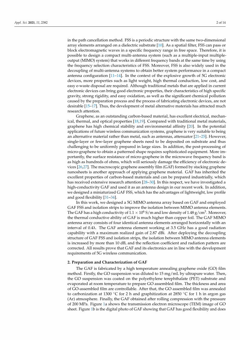
One way is to use GAF FSS to isolate spatial electromagnetic waves, and the other is to set two GAF isolation strips (ISs) between antenna elements to suppress the influence of surface electromagnetic waves. The isolation of the antenna elements can be effectively improved by adjusting the width and the spacing of the two GAF ISs. The optimized width of the GAF IS is 0.5 mm, and the length is consistent with the length of the dielec-tric substrate. The gap between the two GAFS is 3 mm. In addition, the GAF FSS is placed in the middle of two ISs. The substrate of GAF FSS is PET film with a thickness of 0.06 mm, dielectric constant of 3.5 and loss tangent of 0.003. The dimension of the GAF FSS element is 16 mm × 16 mm. The width and total length are 0.5 mm and 39.8 mm, respec-tively, as shown in Figure 5. In practice, FSS can be integrated into the device by means of a card slot. Additionally, for high-power devices, the hollow structure is more benefiting to heat dissipate management.
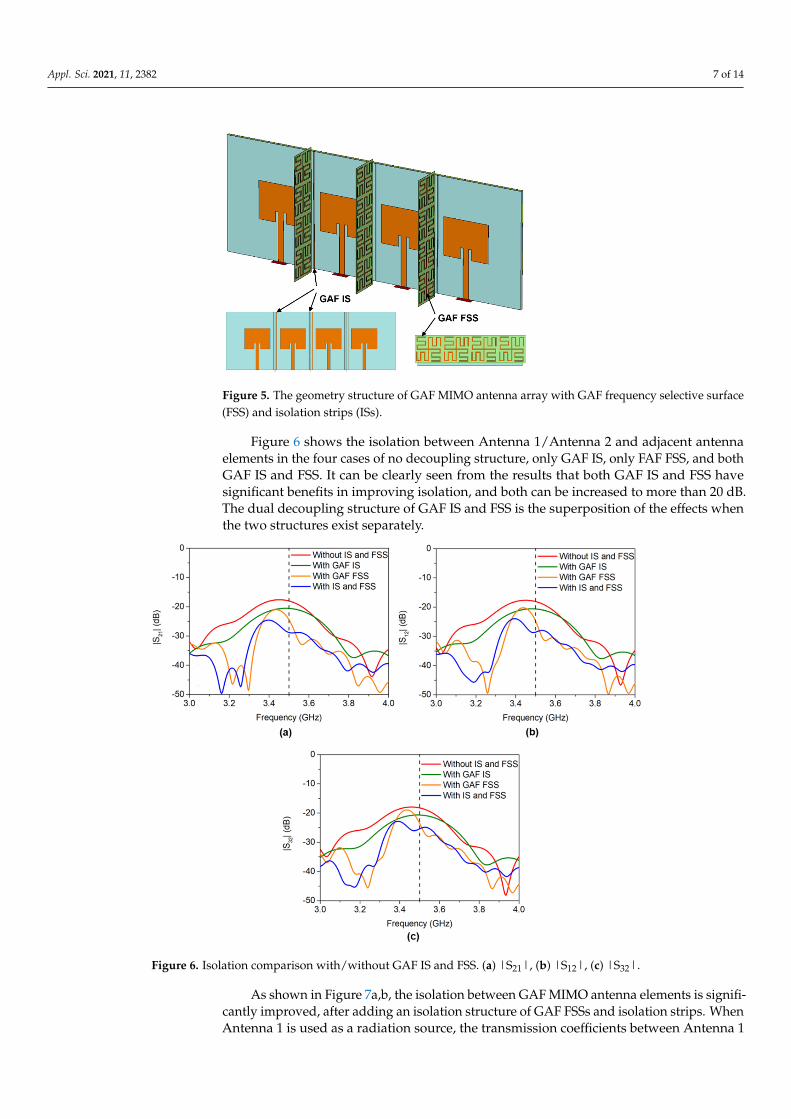
Figure 6 shows the isolation between Antenna 1/Antenna 2 and adjacent antenna elements in the four cases of no decoupling structure, only GAF IS, only FAF FSS, and both GAF IS and FSS. It can be clearly seen from the results that both GAF IS and FSS have significant benefits in improving isolation, and both can be increased to more than
Figure 4. The simulated radiation patterns of GAF MIMO antenna array. (a,b) The E-plane and H-plane radiation patterns of Antenna 1, respectively, (c,d) The E-plane and H-plane radiation patternsof Antenna 2, respectively.
4. Reduce the Coupling of GAF MIMO Antenna Array
We propose two ways to reduce the coupling between MIMO antenna elements. Oneway is to use GAF FSS to isolate spatial electromagnetic waves, and the other is to settwo GAF isolation strips (ISs) between antenna elements to suppress the influence ofsurface electromagnetic waves. The isolation of the antenna elements can be effectivelyimproved by adjusting the width and the spacing of the two GAF ISs. The optimizedwidth of the GAF IS is 0.5 mm, and the length is consistent with the length of the dielectricsubstrate. The gap between the two GAFS is 3 mm. In addition, the GAF FSS is placed inthe middle of two ISs. The substrate of GAF FSS is PET film with a thickness of 0.06 mm,dielectric constant of 3.5 and loss tangent of 0.003. The dimension of the GAF FSS elementis 16 mm × 16 mm. The width and total length are 0.5 mm and 39.8 mm, respectively, asshown in Figure 5. In practice, FSS can be integrated into the device by means of a cardslot. Additionally, for high-power devices, the hollow structure is more benefiting to heatdissipate management.
Appl. Sci. 2021, 11, 2382 7 of 14
Appl. Sci. 2021, 11, x FOR PEER REVIEW 7 of 14
20 dB. The dual decoupling structure of GAF IS and FSS is the superposition of the effects when the two structures exist separately.
Figure 5. The geometry structure of GAF MIMO antenna array with GAF frequency selective sur-face (FSS) and isolation strips (ISs).
Figure 6. Isolation comparison with/without GAF IS and FSS. (a) |S21|, (b) |S12|, (c) |S32|.
As shown in Figure 7a,b, the isolation between GAF MIMO antenna elements is significantly improved, after adding an isolation structure of GAF FSSs and isolation strips. When Antenna 1 is used as a radiation source, the transmission coefficients be-tween Antenna 1 and each antenna are |S21| = −28.82 dB, |S31| = −44.86 dB, |S41| = −51.83 dB. When Antenna 2 is used as a radiation source, the isolation from each antenna is |S12| = −28.57 dB, |S32| = −25.41 dB, |S42| = −43.95 dB. Compared with the initial GAF MIMO antenna array, the isolation is improved by more than 10 dB.
Figure 5. The geometry structure of GAF MIMO antenna array with GAF frequency selective surface(FSS) and isolation strips (ISs).
Figure 6 shows the isolation between Antenna 1/Antenna 2 and adjacent antennaelements in the four cases of no decoupling structure, only GAF IS, only FAF FSS, and bothGAF IS and FSS. It can be clearly seen from the results that both GAF IS and FSS havesignificant benefits in improving isolation, and both can be increased to more than 20 dB.The dual decoupling structure of GAF IS and FSS is the superposition of the effects whenthe two structures exist separately.
Appl. Sci. 2021, 11, x FOR PEER REVIEW 7 of 14
20 dB. The dual decoupling structure of GAF IS and FSS is the superposition of the effects when the two structures exist separately.
Figure 5. The geometry structure of GAF MIMO antenna array with GAF frequency selective sur-face (FSS) and isolation strips (ISs).
Figure 6. Isolation comparison with/without GAF IS and FSS. (a) |S21|, (b) |S12|, (c) |S32|.
As shown in Figure 7a,b, the isolation between GAF MIMO antenna elements is significantly improved, after adding an isolation structure of GAF FSSs and isolation strips. When Antenna 1 is used as a radiation source, the transmission coefficients be-tween Antenna 1 and each antenna are |S21| = −28.82 dB, |S31| = −44.86 dB, |S41| = −51.83 dB. When Antenna 2 is used as a radiation source, the isolation from each antenna is |S12| = −28.57 dB, |S32| = −25.41 dB, |S42| = −43.95 dB. Compared with the initial GAF MIMO antenna array, the isolation is improved by more than 10 dB.
Figure 6. Isolation comparison with/without GAF IS and FSS. (a) |S21|, (b) |S12|, (c) |S32|.
As shown in Figure 7a,b, the isolation between GAF MIMO antenna elements is signifi-cantly improved, after adding an isolation structure of GAF FSSs and isolation strips. WhenAntenna 1 is used as a radiation source, the transmission coefficients between Antenna 1

Appl. Sci. 2021, 11, 2382 8 of 14
and each antenna are |S21| = −28.82 dB, |S31| = −44.86 dB, |S41| = −51.83 dB. When An-tenna 2 is used as a radiation source, the isolation from each antenna is |S12| = −28.57 dB,|S32| = −25.41 dB, |S42| = −43.95 dB. Compared with the initial GAF MIMO antennaarray, the isolation is improved by more than 10 dB.
Appl. Sci. 2021, 11, x FOR PEER REVIEW 8 of 14
Figure 7. (a,b) The simulated S-parameters of GAF MIMO antenna array with GAF FSS and IS. (a) Antenna 1, (b) Antenna 2, (c,d) electric field distribution comparison of Antenna 1 without (c)/with (d) GAF FSS and IS; (e,f) surface current distribution comparison of Antenna 2 without (e)/with (f) GAF FSS and IS.
The surface current can deeply analyze the working mode of the antenna. Figure 7c–f show the surface current of the entire MIMO antenna array when Antenna 1 and An-tenna 2 are used as radiation sources, respectively. When Antenna 1 is used as a radiation source and no decoupling structure is added, there are strongly induced surface currents on Antenna 2, Antenna 3 and Antenna 4, which are caused by the coupling field, as shown in Figure 7c. On the other hand, when GAF FSS and IS are added, there is almost no induced current on the non-radiating antenna, which proves that the decoupling structure suppresses the coupling effect, as shown in Figure 7d. Analogous to the An-tenna 2 as the radiation source, the decoupling structure also suppresses the coupling between the antenna elements, as shown in Figure 7e,f.
Compared with the initial MIMO antenna array, the radiation patterns of the GAF MIMO antenna array with the decoupling structure is modified to normal phase radia-tion, as shown in Figure 8.
Figure 7. (a,b) The simulated S-parameters of GAF MIMO antenna array with GAF FSS and IS. (a) Antenna 1, (b) Antenna2, (c,d) electric field distribution comparison of Antenna 1 without (c)/with (d) GAF FSS and IS; (e,f) surface currentdistribution comparison of Antenna 2 without (e)/with (f) GAF FSS and IS.
The surface current can deeply analyze the working mode of the antenna. Figure 7c–fshow the surface current of the entire MIMO antenna array when Antenna 1 and Antenna2 are used as radiation sources, respectively. When Antenna 1 is used as a radiation sourceand no decoupling structure is added, there are strongly induced surface currents onAntenna 2, Antenna 3 and Antenna 4, which are caused by the coupling field, as shownin Figure 7c. On the other hand, when GAF FSS and IS are added, there is almost noinduced current on the non-radiating antenna, which proves that the decoupling structuresuppresses the coupling effect, as shown in Figure 7d. Analogous to the Antenna 2 asthe radiation source, the decoupling structure also suppresses the coupling between theantenna elements, as shown in Figure 7e,f.
Compared with the initial MIMO antenna array, the radiation patterns of the GAFMIMO antenna array with the decoupling structure is modified to normal phase radiation,as shown in Figure 8.

Appl. Sci. 2021, 11, 2382 9 of 14Appl. Sci. 2021, 11, x FOR PEER REVIEW 9 of 14
Figure 8. (a,b) Radiation pattern of Antenna 1 without (a)/with (b) GAF FSS and IS; (c,d) radiation pattern of Antenna 2 without (c)/with (d) GAF FSS and IS.
5. Measurement of GAF MIMO Antenna Array 5.1. Measurement of GAF Antenna Element
The GAF antenna, FSS and isolation strip are fabricated by laser engraving method with the accuracy of 25 μm. The illustration of Figure 9a shows the digital photo of GAF antenna element. GAF is as the radiator. The performances of GAF antenna element are measured. Figure 9a depicts the reflection coefficient and gain of the GAF antenna ele-ment measured by vector network analyzer (Keysight N5247A PNA) in microwave an-echoic chamber. In the 3.41–3.58 GHz frequency band, |S11| is lower than −10 dB and the gain is greater than 2 dBi, which is consistent with the simulation results. The radiation patterns at 3.5 GHz are displayed in Figure 8b. The GAF antenna element is used as the receiving antenna, and the standard gain horn antenna is used as the transmitting an-tenna. Both the transmitting antenna and the receiving antenna are placed in a micro-wave anechoic chamber and connected with the vector network analyzer. As shown in Figure 9b, the maximum radiation directions of the E-plane and H-plane of the GAF an-tenna element are both in the normal phase.
Figure 8. (a,b) Radiation pattern of Antenna 1 without (a)/with (b) GAF FSS and IS; (c,d) radiationpattern of Antenna 2 without (c)/with (d) GAF FSS and IS.
5. Measurement of GAF MIMO Antenna Array5.1. Measurement of GAF Antenna Element
The GAF antenna, FSS and isolation strip are fabricated by laser engraving methodwith the accuracy of 25 µm. The illustration of Figure 9a shows the digital photo of GAFantenna element. GAF is as the radiator. The performances of GAF antenna element aremeasured. Figure 9a depicts the reflection coefficient and gain of the GAF antenna elementmeasured by vector network analyzer (Keysight N5247A PNA) in microwave anechoicchamber. In the 3.41–3.58 GHz frequency band, |S11| is lower than −10 dB and the gain isgreater than 2 dBi, which is consistent with the simulation results. The radiation patternsat 3.5 GHz are displayed in Figure 8b. The GAF antenna element is used as the receivingantenna, and the standard gain horn antenna is used as the transmitting antenna. Boththe transmitting antenna and the receiving antenna are placed in a microwave anechoicchamber and connected with the vector network analyzer. As shown in Figure 9b, themaximum radiation directions of the E-plane and H-plane of the GAF antenna element areboth in the normal phase.
5.2. Measurement of GAF MIMO Antenna Array
The proposed GAF MIMO antenna array with the decoupling structure of GAF FSSand isolation strip is shown in Figure 10a. Figure 10b,c show the measured reflectioncoefficients of Antenna 1 and Antenna 2, respectively.

Appl. Sci. 2021, 11, 2382 10 of 14Appl. Sci. 2021, 11, x FOR PEER REVIEW 10 of 14
Figure 9. The digital photo and measured reflection coefficient (red line) and gain (green line) (a) and radiation patterns (b) of GAF antenna element.
5.2. Measurement of GAF MIMO Antenna Array The proposed GAF MIMO antenna array with the decoupling structure of GAF FSS
and isolation strip is shown in Figure 10a. Figure 10b,c show the measured reflection co-efficients of Antenna 1 and Antenna 2, respectively.
Figure 10. (a) Digital photo of GAF MIMO antenna arrays with FSS and IS; (a,b) the measured re-flection coefficient of GAF antenna 1 (a) and antenna 2 (b).
Compared with the initial antenna, the operating frequency of the GAF MIMO an-tenna array with the decoupling structure has been corrected and returned to the initial designed of 3.5 GHz.
Figure 9. The digital photo and measured reflection coefficient (red line) and gain (green line) (a) and radiation patterns (b)of GAF antenna element.
Appl. Sci. 2021, 11, x FOR PEER REVIEW 10 of 14
Figure 9. The digital photo and measured reflection coefficient (red line) and gain (green line) (a) and radiation patterns (b) of GAF antenna element.
5.2. Measurement of GAF MIMO Antenna Array The proposed GAF MIMO antenna array with the decoupling structure of GAF FSS
and isolation strip is shown in Figure 10a. Figure 10b,c show the measured reflection co-efficients of Antenna 1 and Antenna 2, respectively.
Figure 10. (a) Digital photo of GAF MIMO antenna arrays with FSS and IS; (a,b) the measured re-flection coefficient of GAF antenna 1 (a) and antenna 2 (b).
Compared with the initial antenna, the operating frequency of the GAF MIMO an-tenna array with the decoupling structure has been corrected and returned to the initial designed of 3.5 GHz.
Figure 10. (a) Digital photo of GAF MIMO antenna arrays with FSS and IS; (a,b) the measured reflection coefficient of GAFantenna 1 (a) and antenna 2 (b).
Compared with the initial antenna, the operating frequency of the GAF MIMO antennaarray with the decoupling structure has been corrected and returned to the initial designedof 3.5 GHz.

Appl. Sci. 2021, 11, 2382 11 of 14
Furthermore, the transmission coefficients of Antenna 1 and non-radiation antenna aremeasured. The decoupling structure obviously suppresses the coupling between MIMOantenna elements. The transmission coefficients of MIMO antenna array with GAF FSS andIS have dropped by more than −10 dB compared with that initial MIMO antenna array, andboth are below −25 dB, as shown in Figure 11. In addition, the radiation patterns of GAFMIMO antenna array with and without decoupling structure are measured, as is illustratedin Figure 12. The results are recorded every 10◦ in microwave anechoic chamber byvector network analyzer. In agreement with the simulated results, the decoupling structurecorrected the radiation patterns of the MIMO antenna array. The H-plane radiation patternsof Antenna 1 (Figure 12b) and Antenna 2 (Figure 12d) without decoupling structure aredeflected by 20◦. On the other hand, the radiation patterns of MIMO antenna array withGAF FSS and IS return to normal phase direction.
Appl. Sci. 2021, 11, x FOR PEER REVIEW 11 of 14
Furthermore, the transmission coefficients of Antenna 1 and non-radiation antenna are measured. The decoupling structure obviously suppresses the coupling between MIMO antenna elements. The transmission coefficients of MIMO antenna array with GAF FSS and IS have dropped by more than −10 dB compared with that initial MIMO antenna array, and both are below −25 dB, as shown in Figure 11. In addition, the radia-tion patterns of GAF MIMO antenna array with and without decoupling structure are measured, as is illustrated in Figure 12. The results are recorded every 10° in microwave anechoic chamber by vector network analyzer. In agreement with the simulated results, the decoupling structure corrected the radiation patterns of the MIMO antenna array. The H-plane radiation patterns of Antenna 1 (Figure 12b) and Antenna 2 (Figure 12d) without decoupling structure are deflected by 20°. On the other hand, the radiation pat-terns of MIMO antenna array with GAF FSS and IS return to normal phase direction.
Figure 11. The measured isolation comparison of MIMO antenna array. (a) |S21|, (b) |S31|, (c) |S41|. Figure 11. The measured isolation comparison of MIMO antenna array. (a) |S21|, (b) |S31|, (c) |S41|.

Appl. Sci. 2021, 11, 2382 12 of 14
Appl. Sci. 2021, 11, x FOR PEER REVIEW 12 of 14
Figure 12. The measured radiation patterns of MIMO antenna array. (a,b) The E-plane and H-plane radiation patterns with/without FSS and IS of Antenna 1, respectively, (c,d) The E-plane and H-plane radiation patterns with/without FSS and IS of Antenna 2, respectively.
6. Conclusions In conclusion, a lightweight graphene-assembled film with high flexibility is pre-
sented. For the first time, we designed a 5G MIMO antenna array based on GAF and employed GAF FSS and isolation strips to improve the isolation between MIMO antenna elements. GAF-based microstrip antenna element working at 3.5 GHz has good radiation ability and high realized gain of 2.87 dBi. GAF FSS and isolation strips can effectively suppress the coupling between MIMO antenna elements and increase the isolation by more than 10 dB. In addition, GAF FSS and isolation strips correct the working frequency and radiation pattern of the MIMO antenna array due to coupling. All results prove that GAF and its electronics are in line with the development requirements of 5G wireless communication and can be a strong candidate as a metal alternative material in next generation wireless communication systems.
Author Contributions: Conceptualization, R.S., X.C. and B.M.; methodology, Z.H., T.L. and D.H.; validation, B.M. and D.H.; writing—original draft preparation, R.S., S.J. and B.M.; review and ed-iting, R.S., D.G.C. and B.M.; funding acquisition, R.S. and D.P. All authors have read and agreed to the published version of the manuscript. R.S. and X.C. contributed equally to this work. All authors have read and agreed to the published version of the manuscript.
Funding: This research was funded by the National Natural Science Foundation of China (No. 51701146) and the Fundamental Research Funds for the Central Universities (WUT: 2020-YB-032 and 2020IB005).
Institutional Review Board Statement: Not applicable.
Informed Consent Statement: Not applicable.
Figure 12. The measured radiation patterns of MIMO antenna array. (a,b) The E-plane and H-planeradiation patterns with/without FSS and IS of Antenna 1, respectively, (c,d) The E-plane and H-planeradiation patterns with/without FSS and IS of Antenna 2, respectively.
6. Conclusions
In conclusion, a lightweight graphene-assembled film with high flexibility is presented.For the first time, we designed a 5G MIMO antenna array based on GAF and employedGAF FSS and isolation strips to improve the isolation between MIMO antenna elements.GAF-based microstrip antenna element working at 3.5 GHz has good radiation ability andhigh realized gain of 2.87 dBi. GAF FSS and isolation strips can effectively suppress thecoupling between MIMO antenna elements and increase the isolation by more than 10 dB.In addition, GAF FSS and isolation strips correct the working frequency and radiationpattern of the MIMO antenna array due to coupling. All results prove that GAF and itselectronics are in line with the development requirements of 5G wireless communicationand can be a strong candidate as a metal alternative material in next generation wirelesscommunication systems.
Author Contributions: Conceptualization, R.S., X.C. and B.M.; methodology, Z.H., T.L. and D.H.;validation, B.M. and D.H.; writing—original draft preparation, R.S., S.J. and B.M.; review and editing,R.S., D.G.C. and B.M.; funding acquisition, R.S. and D.H.; R.S. and X.C. contributed equally to thiswork. All authors have read and agreed to the published version of the manuscript.
Funding: This research was funded by the National Natural Science Foundation of China (No. 51701146)and the Fundamental Research Funds for the Central Universities (WUT: 2020-YB-032 and 2020IB005).
Institutional Review Board Statement: Not applicable.
Informed Consent Statement: Not applicable.
Data Availability Statement: Not applicable.
Conflicts of Interest: The authors declare no conflict of interest.
Appl. Sci. 2021, 11, 2382 13 of 14
References1. Shafi, M.; Molisch, A.F.; Smith, P.J.; Haustein, T.; Zhu, P.; De Silva, P.; Tufvesson, F.; Benjebbour, A.; Wunder, G. 5G: A Tutorial
Overview of Standards, Trials, Challenges, Deployment, and Practice. IEEE J. Sel. Areas Commun. 2017, 35, 1201–1221. [CrossRef]2. Silva, M.M.D.; Guerreiro, J. On the 5G and Beyond. Appl. Sci. 2020, 10, 7091. [CrossRef]3. Liu, F.; Masouros, C.; Li, A.; Sun, H.; Hanzo, L. MU-MIMO Communications with MIMO Radar: From Co-Existence to Joint
Transmission. IEEE Trans. Wirel. Commun. 2018, 17, 2755–2770. [CrossRef]4. Lu, D.; Wang, L.; Yang, E.; Wang, G. Design of High-Isolation Wideband Dual-Polarized Compact MIMO Antennas With
Multiobjective Optimization. IEEE Trans. Antennas Propag. 2018, 66, 1522–1527. [CrossRef]5. Hu, H.; Chen, F.; Chu, Q. A Compact Directional Slot Antenna and Its Application in MIMO Array. IEEE Trans. Antennas Propag.
2016, 64, 5513–5517. [CrossRef]6. Anitha, R.; Vinesh, P.V.; Prakash, K.C.; Mohanan, P.; Vasudevan, K. A Compact Quad Element Slotted Ground Wideband Antenna
for MIMO Applications. IEEE Trans. Antennas Propag. 2016, 64, 4550–4553. [CrossRef]7. Wen, L.; Gao, S.; Luo, Q.; Mao, C.; Hu, W.; Yin, Y.; Zhou, Y.; Wang, Q. Compact Dual-Polarized Shared-Dipole Antennas for Base
Station Applications. IEEE Trans. Antennas Propag. 2018, 66, 6826–6834. [CrossRef]8. Makar, G.; Tran, N.; Karacolak, T. A High-Isolation Monopole Array with Ring Hybrid Feeding Structure for In-Band Full-Duplex
Systems. IEEE Antenn. Wirel. Propag. Lett. 2017, 16, 356–359. [CrossRef]9. Sui, J.; Wu, K. Self-Curing Decoupling Technique for Two Inverted-F Antennas with Capacitive Loads. IEEE Trans. Antennas
Propag. 2018, 66, 1093–1101. [CrossRef]10. Anwar, R.; Mao, L.; Ning, H. Frequency Selective Surfaces: A Review. Appl. Sci. 2018, 8, 1689. [CrossRef]11. Chen, Y.; Zhao, J.; Yang, S. A Novel Stacked Antenna Configuration and its Applications in Dual-Band Shared-Aperture Base
Station Antenna Array Designs. IEEE Trans. Antennas Propag. 2019, 67, 7234–7241. [CrossRef]12. Saleem, R.; Bilal, M.; Chattha, H.T.; Ur Rehman, S.; Mushtaq, A.; Shafique, M.F. An FSS Based Multiband MIMO System Incorporating
3D Antennas for WLAN/WiMAX/5G Cellular and 5G Wi-Fi Applications. IEEE Access 2019, 7, 144732–144740. [CrossRef]13. Zhu, Y.; Chen, Y.; Yang, S. Decoupling and Low-Profile Design of Dual-Band Dual-Polarized Base Station Antennas Using
Frequency-Selective Surface. IEEE Trans. Antennas Propag. 2019, 67, 5272–5281. [CrossRef]14. Das, G.; Sahu, N.K.; Sharma, A.; Gangwar, R.K.; Sharawi, M.S. FSS-Based Spatially Decoupled Back-to-Back Four-Port MIMO
DRA With Multidirectional Pattern Diversity. IEEE Antenn. Wirel. Propag. Lett. 2019, 18, 1552–1556. [CrossRef]15. Awasthi, A.K.; Li, J.; Koh, L.; Ogunseitan, O.A. Circular economy and electronic waste. Nat. Electron. 2019, 2, 86–89. [CrossRef]16. Masoudi, M.; Khafagy, M.G.; Conte, A.; El-Amine, A.; Francoise, B.; Nadjahi, C.; Salem, F.E.; Labidi, W.; Sural, A.; Gati, A.; et al.
Green Mobile Networks for 5G and Beyond. IEEE Access 2019, 7, 107270–107299. [CrossRef]17. Awasthi, A.K.; Wang, M.; Awasthi, M.K.; Wang, Z.; Li, J. Environmental pollution and human body burden from improper
recycling of e-waste in China: A short-review. Environ. Pollut. 2018, 243, 1310–1316. [CrossRef]18. Novoselov, K.S.; Geim, A.K.; Morozov, S.V.; Jiang, D.; Zhang, Y.; Dubonos, S.V.; Grigorieva, I.V.; Firsov, A.A. Electric field effect in
atomically thin carbon films. Science 2004, 306, 666–669. [CrossRef] [PubMed]19. Novoselov, K.S.; Geim, A.K.; Morozov, S.V.; Jiang, D.; Katsnelson, M.I.; Grigorieva, I.V.; Dubonos, S.V.; Firsov, A.A. Two-
dimensional gas of massless Dirac fermions in graphene. Nature 2005, 438, 197–200. [CrossRef]20. Xin, G.; Yao, T.; Sun, H.; Scott, S.M.; Shao, D.; Wang, G.; Lian, J. Highly thermally conductive and mechanically strong graphene
fibers. Science 2015, 349, 1083–1087. [CrossRef] [PubMed]21. Esquius-Morote, M.; Gomez-Diaz, J.S.; Perruisseau-Carrier, J. Sinusoidally Modulated Graphene Leaky-Wave Antenna for
Electronic Beamscanning at THz. IEEE Trans. Terahertz Sci. Technol. 2014, 4, 116–122. [CrossRef]22. Cabellos-Aparicio, A.; Llatser, I.; Alarcon, E.; Hsu, A.; Palacios, T. Use of Terahertz Photoconductive Sources to Characterize
Tunable Graphene RF Plasmonic Antennas. IEEE Trans. Nanotechnol. 2015, 14, 390–396. [CrossRef]23. Carrasco, E.; Perruisseau-Carrier, J. Reflectarray Antenna at Terahertz Using Graphene. IEEE Antenn. Wirel. Propag. Lett. 2013, 12,
253–256. [CrossRef]24. Dragoman, M.; Neculoiu, D.; Bunea, A.; Deligeorgis, G.; Aldrigo, M.; Vasilache, D.; Dinescu, A.; Konstantinidis, G.; Mencarelli,
D.; Pierantoni, L.; et al. A tunable microwave slot antenna based on graphene. Appl. Phys. Lett. 2015, 106, 153101. [CrossRef]25. Bozzi, M.; Pierantoni, L.; Bellucci, S. Applications of Graphene at Microwave Frequencies. Radioengineering 2015, 24, 661–669. [CrossRef]26. Dashti, M.; Carey, J.D. Graphene Microstrip Patch Ultrawide Band Antennas for THz Communications. Adv. Funct. Mater. 2018,
28, 1705925. [CrossRef]27. Fan, C.; Wu, B.; Song, R.; Zhao, Y.; Zhang, Y.; He, D. Electromagnetic shielding and multi-beam radiation with high conductivity
multilayer graphene film. Carbon 2019, 155, 506–513. [CrossRef]28. Shen, B.; Zhai, W.; Zheng, W. Ultrathin Flexible Graphene Film: An Excellent Thermal Conducting Material with Efficient EMI
Shielding. Adv. Funct. Mater. 2014, 24, 4542–4548. [CrossRef]29. Xin, G.; Sun, H.; Hu, T.; Fard, H.R.; Sun, X.; Koratkar, N.; Borca-Tasciuc, T.; Lian, J. Large-Area Freestanding Graphene Paper for
Superior Thermal Management. Adv. Mater. 2014, 26, 4521–4526. [CrossRef] [PubMed]30. Feng, S.; Yao, T.; Lu, Y.; Hao, Z.; Lin, S. Quasi-industrially produced large-area microscale graphene flakes assembled film with
extremely high thermoelectric power factor. Nano Energy 2019, 58, 63–68. [CrossRef]31. Song, R.; Zhao, X.; Wang, Z.; Fu, H.; Han, K.; Qian, W.; Wang, S.; Shen, J.; Mao, B.; He, D. Sandwiched Graphene Clad Laminate:
A Binder-Free Flexible Printed Circuit Board for 5G Antenna Application. Adv. Eng. Mater. 2020, 22, 2000451. [CrossRef]

Appl. Sci. 2021, 11, 2382 14 of 14
32. Song, R.; Wang, Q.; Mao, B.; Wang, Z.; Tang, D.; Zhang, B.; Zhang, J.; Liu, C.; He, D.; Wu, Z.; et al. Flexible graphite films withhigh conductivity for radio-frequency antennas. Carbon 2018, 130, 164–169. [CrossRef]
33. Song, R.; Wang, Z.; Zu, H.; Chen, Q.; Mao, B.; Wu, Z.P.; He, D. Wideband and low sidelobe graphene antenna array for 5Gapplications. Sci. Bull. 2020. [CrossRef]
34. Zhang, J.; Song, R.; Zhao, X.; Fang, R.; Zhang, B.; Qian, W.; Zhang, J.; Liu, C.; He, D. Flexible Graphene-Assembled Film-BasedAntenna for Wireless Wearable Sensor with Miniaturized Size and High Sensitivity. ACS Omega 2020, 5, 12937–12943. [CrossRef]