A graph-theoretic method for organizing overlapping ...
31
Joumal of Classification 12:283-313 (1995) A Graph-Theoretic Method for Organizing Overlapping Clusters into Trees, Multiple Trees, or Extended Trees J. Douglas CarroU Rutgers University James E. Corter Teachers CoUege, Columbia University Abstract: A clustering that consists of a nested set of clusters may be represented graphically by a tree. In contrast, a clustedng that includes non-nested ovedapping clusters (sometimes termed a "nonhierarchical' ' cluste¡ cannot be represented by a tree. Graphical representations of such non-nested ovedapping clusterings are usuaUy complex and difficult to interpret. Carroll and Pruzansky (1975, 1980) sug- gested representing non-nested clusterings with multiple ultramet¡ or additive trees. Corter and Tversky (1986) introduced the extended tree (EXTREE) model, which represents a non-nested structure asa tree plus ovedapping clusters that ate represented by marked segments in the tree. We show here that the problem of finding a nested (i.e., tree-structured) set of clusters in ah ovedapping clustering can be reformulated as the problem of finding a clique in a graph. Thus, clique- finding algo¡ can be used to identify sets of clusters in the solution that can be represented by trees. This formulation provides a means of automaticaUy con- structing a multiple tree or extended tree representation of any non-nested cluster- ing. The method, called "clustrees", is applied to several non-nested overlapping clusterings de¡ using the MAPCLUS program (Arabie and Carroll 1980). Keywords: Overlapping clustering; Ultrametric; Additive tree; Extended tree; Multiple trees; Graph; Clique; Proximities. Authors' addresses: Please address correspondence to: James Corter, Box 41, Teachers College, Columbia University, New York, NY 10027, USA. tel. (212) 678-3843. Intemet: [email protected]
Transcript of A graph-theoretic method for organizing overlapping ...

Joumal of Classification 12:283-313 (1995)
A Graph-Theoretic Method for Organizing Overlapping Clusters into Trees, Multiple Trees, or Extended Trees
J. Douglas CarroU
Rutgers University
James E. Corter
Teachers CoUege, Columbia University
Abstract: A clustering that consists of a nested set of clusters may be represented graphically by a tree. In contrast, a clustedng that includes non-nested ovedapping clusters (sometimes termed a "nonhierarchical' ' cluste¡ cannot be represented by a tree. Graphical representations of such non-nested ovedapping clusterings are usuaUy complex and difficult to interpret. Carroll and Pruzansky (1975, 1980) sug- gested representing non-nested clusterings with multiple ultramet¡ or additive trees. Corter and Tversky (1986) introduced the extended tree (EXTREE) model, which represents a non-nested structure a sa tree plus ovedapping clusters that ate represented by marked segments in the tree. We show here that the problem of finding a nested (i.e., tree-structured) set of clusters in ah ovedapping clustering can be reformulated as the problem of finding a clique in a graph. Thus, clique- finding algo¡ can be used to identify sets of clusters in the solution that can be represented by trees. This formulation provides a means of automaticaUy con- structing a multiple tree or extended tree representation of any non-nested cluster- ing. The method, called "clustrees", is applied to several non-nested overlapping clusterings de¡ using the MAPCLUS program (Arabie and Carroll 1980).
Keywords: Overlapping clustering; Ultrametric; Additive tree; Extended tree; Multiple trees; Graph; Clique; Proximities.
Authors' addresses: Please address correspondence to: James Corter, Box 41, Teachers College, Columbia University, New York, NY 10027, USA. tel. (212) 678-3843. Intemet: [email protected]

284 J.D. Carroll and J.E. Corter
1. Introduction
Hierarchical clustering methods may be useful for exploratory analyses of domains even where there is no a pr ior i reason to expect a hierarchical structure, that is, one consisting of nested clusters. 1 One reason the methods may be useful in such a wide variety of applications is that the tree graphs used to represent the solutions are easy to interpret and have many useful pro- perties. Also, the algorithms used to fit hierarchical models to proximity data are relatively efficient, hence practical to apply even to large data sets.
Nonetheless, there are many possible patterns of proximities between objects that cannot be represented well by hierarchical cluster solutions or trees, because hierarchical clusterings are necessarily rest¡ to solutions consisting of nested sets of clusters. This limitation has led researchers to propose more general clustering models and associated numerical methods with the capability of representing non-nested sets of clusters. Two such "nonhierarchical" models described in the psychological literature are the additive cluste¡ or ADCLUS model (Shepard and Arabie 1979; Arabie and Carroll 1980; Carroll and Arabie 1983) and the extended tree (EXTREE) model (Corter and Tversky 1986), both discussed in more detail below. The ability of these nonhierarchical or overlapping cluster methods to accommo- date a wide variety of data structures is bought at a price, however. The number of possible non-nested cluster solutions is much larger than the number of nested solutions. Furthermore, the algo¡ typically used to fit hierarchical cluster models are simple and relatively efficient, but the algo- rithms that are most widely used to fitting overlapping cluster solutions are relatively costly computationally. Finally, the graphical representation of a non-nested structure is usually more complex than a tree.
Several different methods have been used to represent non-nested clus- ter solutions graphically. One approach (e.g., Shepard and Arabie 1979) has been to represent the objects to be clustered as points in the plane, then to draw contours around sets of points that correspond to clusters in the solution. While this method may provide useful displays, it has certain limitations.
1. We distinguish between nested clusterings and non-nested (overlapping) cluste¡ We use the term nested to refer to cluster solutions in which each pair of clusters is either disjoint (i.e., the two clusters have no members in common) or one cluster is a proper subset of the other. We use the temas non-nested or overlapping to refer to clusterings in which two distinct clusters may overlap without one being a subset of the other. Note that some authors use the terna nested in a stronger sense, to denote only those sets of clusters that can be strictly ordered in such a way that for any pair of clusters ck and ck., k < k', ck is a proper subset of c~-.

A Graph-Theoretic Method 285
With a large number of clusters, the contour lines may intersect repeatedly and become hard to follow. Also, the weight of each cluster is usually not represented by any aspect of t¡ display. Finally, automating the construc- tion of such a space-plus-contours representation would require quite sophis- ticated computer graphics programming.
Two other approaches to representing non-nested cluster solutions seek to avoid these limitations of the space-plus-contours representation by utiliz- ing the readability of trees. Carroll and Pruzansky (1975, 1980) proposed representing non-nested clusterings by multiple trees. Corter and Tversky's (1986) extended tree (EXTREE) model extends the familiar notion of a tree by introducing marked segments on the arcs of the tree to represent features that "cut across" the basic tree structure.
Both these approaches offer the possibility of representing non-nested cluster structures with readable, tree-like graphs. However, using these types of graphical displays for non-nested cluster solutions has not been explored except in connection with the specific algorithms proposed by CarroU and Pruzansky (1975, 1980) and Corter and Tversky (1986). But the algo¡ introduced by Carroll and Pruzansky (1975) is clearly not a general algorithm for fitting non-nested cluster solutions, nor is it intended as such. Similarly, although extended trees can be used to represent any non-nested cluster struc- ture, the EXTREE algorithm introduced by Corter and Tversky (1986) may also be biased toward finding tree-like structures, because the initial stage of the algorithm attempts to fit the best additive tree to the data, using a va¡ of Sattath and Tversky's (1977) ADDTREE algofithm.
Accordingly, it seems useful to explore how multiple trees and extended trees might be used to represent any non-nested cluste¡ regard- less of the algorithm used to de¡ that solution. For example, one of the most general algo¡ described to date for fitting non-nested clusters to proximity data is incorporated in the MAPCLUS program (Arabie and Carroll 1980), which uses a mathematical programming approach to fit the ADCLUS model (Shepard and Arabie 1979). The user specifies how many clusters the program should search for, and the program then seeks the best-fitting set of clusters. Because of the nature of the algo¡ there is no a priori reason to suspect MAPCLUS of bias toward finding nested subsets, as there is with the multiple tree and EXTREE algo¡
The goal of the present work is to develop formal methods for representing non-nested cluster solutions as extended trees or as multiple trees. The central problem to be solved in this endeavor is to find a method for identifying nested subsets of clusters in a clustering solution, since any nested subset of clusters can be represented as a tree. Thus, extended trees or multiple trees could be used to represent cluster solutions derived from any nonhierarchical clustering algo¡ such as MAPCLUS. Also, such methods

286 J.D. Carroll and J.E. Corter
for finding and comparing trees might be useful for choosing among alterna- tive extended tree or multiple tree representations.
In this paper we describe how the set of clusters comprising a non- nested clustering together with the set relationships a m o n g these clusters can
be represented a sa graph N (to be defined at a later point), called the "nest- ing graph" of the clustering. We then show that the problem of finding a nested subset of clusters (that is, a set that can be represented asa rooted tree) is equivalent to the problem of finding a clique in the nesting graph (N) of the clustering. Based on this result, we develop a method for finding all nested subsets of clusters that correspond to trees. We describe the implementation of the method in a PASCAL program that incorporates a standard algo¡ (Bron and Kerbosch 1971) for enumerating the cliques of a graph. We also discuss the problem of deriving estimates of arc lengths in the resulting tree or extended tree graphs, and show how the results of Sattath and Tversky (1987) apply to this problem. Finally, we present several applications of the method, called "clustrees", to find multiple tree and extended tree represen- tations of non-nested clusterings.
2. Non-Nested Cluster Models
2.1 Additive Clustering
The additive clustering or ADCLUS model introduced by Shepard and Arabie (1979) predicts the sirnilarity s (x i , x j ) between two objects xi and xi
( i , j = 1,2 . . . . . n ) as the weighted sum of the features they share. That is,
m
S(Xi,Xj) = Z WkPikPjk q" A (1) k=l
where m i s the number of features, wk is the weight or salience of the k-th feature, and Pik is an indicator variable which is equal to 1 if object x i
possesses the k-th feature, and 0 otherwise. The scalar A denotes an additive constant. Under one interpretation (perhaps most appropriate when the data are thought of as interval scale), this additive constant is included merely to equate the zero points of the scales of the observed data and the predicted similarities. Alternatively, A may be viewed as the weight for the "universal cluster", the cluster consisting of all objects. Under this latter interpretation, however, the above equation can be written without the A term, since this universal cluster can be represented as the (m + 1)-st feature, with weight wm+ 1 . T h e ADCLUS model can be written in matrix notation as

A Graph-Theoretic Method 287
= P W P " + A , (2)
where S is a symmetric n x n matrix of predicted proximities, P is an n x m matrix with elements Pik, W is a diagonal matrix of non-negative feature weights, and A is an n x n matrix of elements all equal to the additive con- stant. Again, if P i s extended to include an (m + 1)-st column representing the "universal cluster", then this equation can be written without an explicit A term. For comparison with the EXTREE model described below, it is use- fui to express the model in terms of dissimilarities:
^ m
d(xi,xj) = A ' - ~_, WkPikPj k k=l
Here d(xi ,xj) refers to the predicted dissimilarity between distinct objects x i and xi, and A" is an additive constant.
2.2 Extended Trees
The extended tree or EXTREE model (Corter and Tversky 1986), represents non-nested feature structures graphically by a generalization of the additive tree. An additive tree (sometimes termed a "path length tree" or "free tree") graph is a tree in which each arc is associated with a weight that is represented graphically by the length of the arc. The distance between two nodes in the tree is defined as the sum of arc lengths in the (unique) path con- necting the nodes - i.e. the "path length" distance. The term "path-length tree" de¡ from this fact, while the term "additive tree" emphasizes that the distances are an additive function of the arc lengths. Objects are usually represented as terminal nodes (" leaves") of the tree; that is, nodes of degree one. Mathematically, distances in an additive tree satisfy the additive ine- quality (also known as the "tree inequality" or the "four-point condition"), which states that any~ four objects may be labeled x i , xi, Xk, xt such that d(xi,xj) + d(Xk,Xl) < d(x i,Xk) + d(xj,xl) = d(xi,xl) + d(xj,xk). A special case of the additive tree is the ultramet¡ tree. Distances in an ultramet¡ tree satisfy the more rest¡ ultramet¡ inequality, which states that any three objects may be labeled xi, xi, x t such that d(x i,xj) < d(x i,xk) = d(xj,Xk). An ultrametric tree has a unique root; an additive tree has no "natural" root, hence the root may be arbitra¡ placed on any arc or at any node in the graph. Each different root placement results in a different display of the tree but does not affect the interobject distances. As discussed later, the nodes of a rooted additive or ultrametric tree define a set of clusters, each cluster corresponding to the set of leaves of the subtree "be low" a particular node.

288 J.D. Carroll and J.E. Corter
The extended tree graph extends the notion of the additive tree in the following way. To the basic additive tree ate added marked segments representing clusters that "cut across" the clusters of the tree structure. Thus, the graphical representation divides the set of clusters into a nested set, represented by the tree structure, and another set (not nested with the first set), represented by the marked segments. We use the terms 'extended tree' or 'EXTREE' to refer both to the graphical representation of the solution and to the mathematical model that underlies this representation, which is a spe- cial case of the general distinctive features model (Tversky 1977). The extended tree model represents the dissimilarity between two objects xi and xi as the sum of the weights of the clusters to which xi (but not xi) belongs plus the weights of the clusters to which xi (but not xi) belongs. The extended tree model can be expressed in terms of dissimilarities as
^ m
d(xi,xj) = ~.j Wk I Pik--Pjk I . (3) k=l
The model thus is a weighted version of a set-difference or Hamming met¡
2.3 Common Features Versus Distinctive Features Models
It is sometimes useful to interpret clusters as representing features or sets of features shared by the objects comp¡ that cluster (Tversky 1977; Sattath and Tversky 1977). Thus, the P mat¡ of Equation (2) can be thought of as representing a feature structure for the set of objects, in which entry Pik is equal to 1 if the i-th object possesses feature k, and 0 otherwise. Given such a feature structure, proximities can be defined between pairs of objects according to one of two models, the common features model or the distinctive features model. Both are special cases of Tversky's (1977) contrast model of simila¡ (sometimes referred to as the feature-matching model).
The contrast model expresses the dissimila¡ between two objects x and y as
^
d(x,y) = - 0g(X n Y) + c t f (X - Y) + ~ f ( Y - X ) ,
where X and Y denote the feature sets of x and y, respectively. 2 Thus, X n Y

A Graph-Theoretic Method 289
denotes the set of features possessed by both x and y (the "common features" of x and y) and X - Y the set of features possessed by x but not y (the "dis- tinctive features" of x). The ADCLUS model corresponds to the special case in which ~ = 13 = 0 and g is an additive function defining the weights of the common feature sets. The EXTREE model is the symmetric additive version of the distinctive features part of the model (i.e., ~ = 0, ~ = [3).
3. Finding Trees in a Non-Nested Clustering
3.1 Representing a Clustering by a Graph
A number of authors have explored graph-theoretic approaches to cer- tain clustering problems (for reviews see Sneath and Sokal 1973, pp. 253- 256; Godehardt 1988, Ch. 3). We describe one way to representa clustering a s a graph, and show that this approach can be used to find subsets of the cluster solution that can be represented graphically as trees. This method can be used to represent any non-nested clustering as an extended tree oras mul- tiple trees.
To representa clustering solution as an extended tree, it is necessary to divide the clusters into two groups: one (nested) group which can be represented as a tree, and a second (possibly non-nested) group to be represented by marked segments. Since the marked segments add visual complexity to the representation, it is desirable to relegate as many clusters as possible to the nested group, i.e., to find the tree that includes the maximal number of clusters. We will refer to this problemas the maximal tree prob- lem.
A different problem must be solved to find a parsimonious multiple tree representation of a nonhierarchical clustering, that involves finding several nested sets of clusters (i.e., trees) that jointly include the entire set of clusters. Since using multiple trees also increases the visual and interpretive complex- ity of the representation, it is desirable to find the minimal set of tree gmphs
2. Here and in subsequent sections, we use unsubsc¡ lowercase letters (x,y,..) to refer to the objects being clustered, and upper-case letters (X, Y,..) to refer to the corresponding feature sets. This switch in notation is desirable because using subsc¡ notation for objects and feature sets is less legible (because of the small size of the subsc¡ that would be needed to distinguish objects and feature sets), is highly confusable with the subscript notation that will be used for clusters of objects (and nodes of a graph), and is inconsistent with the literature on feature-based models (e.g., Tversky 1977; Sattath & Tversky 1987).

290 J.D. Carroll and J.E. Corter
that include all clusters of the overlapping clustering. We wiU refer to this as the minimal tree covering or the multiple tree problem.
Algorithms to solve these problems can be found by converting them into standard graph theory problems. In the next sections we present some background, then describe the representation of and solution to these prob- lems using graphs.
3.2 Background and Definitions
In this section we review relevant concepts from graph theory, and introduce some new definitions. Readers seeking more detail may consult a general reference on graph theory, such as Golumbic (1980). We define a graph G a s a collection of vertices (or "nodes") V, together with a set of edges E defined on V x V, i.e., G = <V, E>. We will be concemed only with undirected graphs, that is, graphs for which the relationship E is symmetric (i.e., (v k , v l ) ~ E ~ ( v l , v k ) ~ E ) . A subset of vertices V" in a graph G(V" c V), plus the edges E" connecting any pair of those vertices (E" c E), is said to be a subgraph G" of G. If each pair of vertices in G" is connected by an edge, then G" is a complete subgraph of G. A clique of G is defined as a maximal complete subgraph of G, that is, a complete subgraph of G not con- tained in any other complete subgraph. A clique is said to be a maximum clique if no other clique of G exists that contains a greater number of vertices.
To reformulate the tree representation problems using graphs, we begin by introducing some notation. Let U (for "universal set") denote the o¡ set of objects to be clustered. A clustering C is defined to be a set of m dis- tinct nonempty sets or clusters, C = {cl ,c2, ""Cm}. Each cluster Ck is com- posed of some subset of the original set of n objects.
We will now proceed to define some specialized graphs using the set relationships among the clusters of C. Given clustering C, it is easy to see that for any two distinct clusters ck and Cl exactly one of the following three relations between the two sets holds:
R 1: Ck C3 cl = ~ (disjointness)
R2: c k c ct v ck D c I (inclusion)
R3: Ck C3 ct ~ d~, Ck C~ cl, Ck OZ c~ (overlap)
Note that R3 can also be defined using R1 and R2:R3 holds if not(R1) and not(R2).
A Graph-Theoretic Method 291
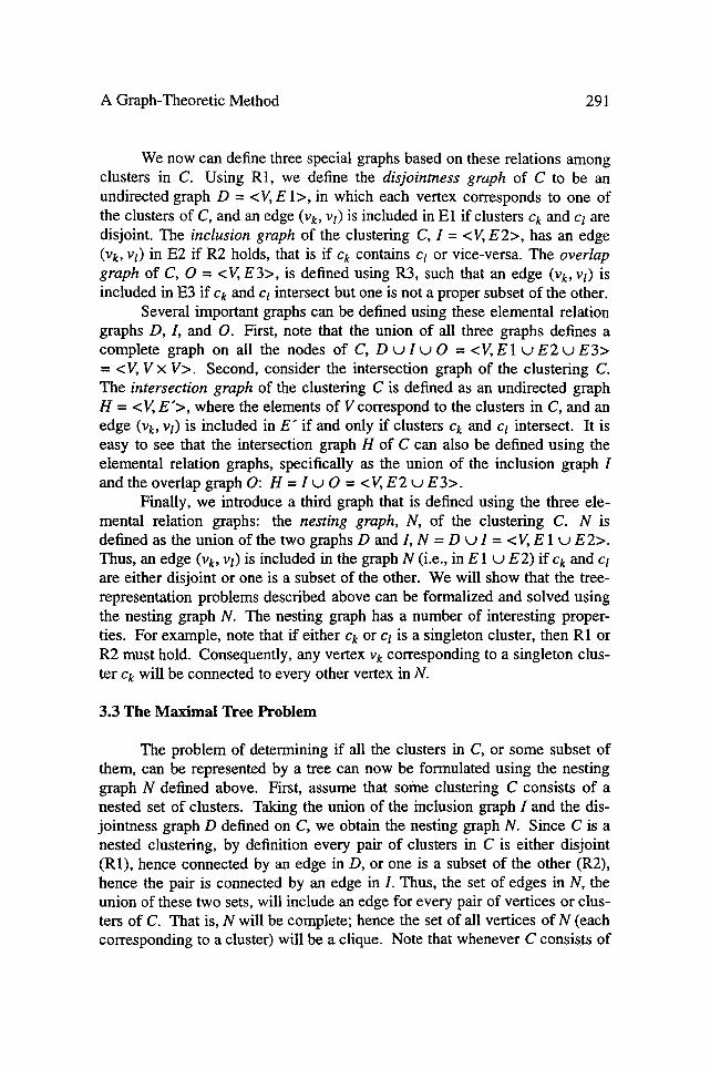
We now can define three special graphs based on these relations among clusters in C. Using R1, we define the disjointness graph of C to be an undirected graph D = <V, E 1>, in which each vertex corresponds to one of the clusters of C, and an edge (Vk, V l) is included in El if clusters Ck and c l are disjoint. The inclusion graph of the clustering C, I = <V, E2>, has an edge (Vk, Vl) in E2 if R2 holds, that is if ck contains ct or vice-versa. The overlap graph of C, O = <V, E3>, is defined using R3, such that an edge (Vk, vl) is included in E3 if Ck and Cl intersect but one is no t a proper subset of the other.
Several important graphs can be de¡ using these elemental relation graphs D , / , and O. First, note that the union of aU three graphs defines a complete graph on all the nodes of C, D u I u O = <V, E 1 u E2 t j E 3> = <V, V x V>. Second, consider the intersection graph of the clustering C. The intersection graph of the cluste¡ C is defined as an undirected graph H = < V, E '> , where the elements of V correspond to the clusters in C, and an edge (Vk, vi) is included in E" if and only if clusters ck and cl intersect. It is easy to see that the intersection graph H of C can also be defined using the elemental relation graphs, specifically as the union of the inclusion graph I and the overlap graph O: H = I u O -- <V, E 2 u E3>.
FinaUy, we introduce a third graph that is defined using the three ele- mental relation graphs: the nesting graph, N, of the clustering C. N is defined as the union of the two graphs D and I, N = D u I = < V, E 1 u E 2>. Thus, an edge (v k, vi) is included in the graph N (i.e., in E I u E2) if Ck and cl are either disjoint or one is a subset of the other. We will show that the tree- representation problems desc¡ above can be formalized and solved using the nesting graph N. The nesting graph has a number of interesting proper- ties. For example, note that if either Ck or ct is a singleton cluster, then R1 or R2 must hold. Consequently, any vertex v k corresponding to a singleton clus- ter ck will be connected to every other vertex in N.
3.3 The Maximal Tree Problem
The problem of determining if all the clusters in C, or some subset of them, can be represented by a tree can now be formulated using the nesting graph N defined above. First, assume that some clustering C consists of a nested set of clusters. Taking the union of the inclusion graph I and the dis- jointness graph D defined on C, we obtain the nesting graph N. Since C is a nested cluste¡ by de¡ every pair of clusters in C is either disjoint (R1), hence connected by an edge in D, or one is a subset of the other (R2), hence the pair is connected by an edge in I. Thus, the set of edges in N, the union of these two sets, will include an edge for every pair of vertices or clus- ters of C. That is, N will be complete; hence the set of all vertices of N (each corresponding to a cluster) will be a clique. Note that whenever C consists of

292 J.D. Carroll and J.E. Correr
a nested set of clusters and includes both the universal cluster anda singleton cluster corresponding to each of the objects to be clustered, then the inclusion graph I of C defined using relation R2 includes a sa subgraph the actual tree graph that is to be constructed to represent the clustering. Consequently, the tree graph itself is also a subgraph of N.
Now considera cluste¡ C in which the clusters are not nested, that is, for at least one pair of clusters (ck, ct) in C, R3 holds. Then the nesting graph N of the set of clusters in C will not be complete, since for the pair (ck, Cl) neither R1 nor R2 holds. However, in this case there may exista sub- set Ct of clusters that forms a nested set, i.e., for every pair of clusters in Ct either R1 or R2 holds. In this case the nesting graph Nt constmcted from Ct will be complete. If in addition no cluster ck (not in Ct) exists that is either disjoint or nested with every cluster in Ct, then it follows that Nt is a maximal complete subgraph of N, i.e., a clique. Conversely, every clique Nt in the graph N corresponds to a "maximal tree" in the cluster solution C, that is, a nested subset of C for which no other cluster ck exists that is either disjoint (R1) or nested (R2) with every member of the subset. If such a cluster ck did exist, it would forma complete subgraph with the nodes already in N t, conse- quently Ni could not be a clique. Thus, the problem of finding maximal nested subsets (i.e., trees) in a clustering can be reformulated as the problem of finding cliques in a graph (specifically, in the nesting graph N). Algo- rithms for solving this standard problem are reviewed in a subsequent section. If N has more than one clique, then any maximum clique is of particular interest, because a maximum clique corresponds to a tree that includes the maximal number of clusters. Note, however, tbat the maximum clique may not be unique: there may be more than one clique containing the maximal number of clusters.
In practical applications of this method, any singleton cluster consist- ing of a single object can be excluded from the construction of the graph N, because (as mentioned above) any cluster consisting of a single object must be either disjoint with (R1) or included in (R2) any other cluster. Thus, if a singleton cluster is included in C, the corresponding vertex must be part of every clique of N. Similarly, the universal cluster consisting of all objects includes (R2) all other clusters; hence the corresponding vertex will be a member of every clique of N. Accordingly, if either of these special types of cluster is included in C, in practical applications it may be excluded from the construction of N and the subsequent search for cliques. However, these clus- ters are usuaUy represented in the actual tree or extended tree graphs that result from application of the method.

A Graph-Theoretic Method 293
3.4 The Multiple Tree Problem
Since each clique of N corresponds to a tree that can be constructed to represent its constituent clusters, finding the minimal multiple tree representa- tion of a clustering can be accomplished by finding the minimum (vertex) covering of N by cliques. A vertex clique covering of a graph G is a set of cliques such that each vertex of G is included in at least one of the cliques. In this paper we will use "clique cove¡ to mean a vertex clique covering. By "mŸ clique covering" we mean a vertex clique covering that includes the mŸ necessary number of cliques.
Although we refer to the covering we seek as the minimum vertex clique covering, a second consideration might affect our choice of the "bes t" clique covering. This second consideration is that complications in represen- tation a¡ to the extent that two cliques intersect. Any cluster that is in more than one clique may potentially be represented in any of the trees correspond- ing to those cliques. Alternatively, the cluster might be represented in each of the trees with reduced weight in each. However, the decision to put the cluster into one tree or another, or how to aUocate the cluster's weight among the trees, will usually be made for "extemal" reasons, perhaps on the basis of interpretability. This practice presents difficulties in automating the method. Furthermore, representing the cluster in more than one tree increases the apparent complexity of the representation. Thus, the best covering for our purposes would consist of a set of cliques corresponding to mutually exclusive and exhaustive subsets, that is, a set of cliques constituting a parti- tion of the nodes o fN (equivalently, of the set of clusters C).
More than one approach might be taken to try to optimize both of the above crite¡ simultaneously. One general solution could be found by designing a joint function to be optimized that combines both of these factors: the number of cliques in the covering and the degree of overlap of the cliques. Both constraints can be expressed in a loss criterion of the form:
(2 (2 l = ~u ((Za'tq + Ii) = O�91 ~_~ nq + ~Q,
q q (4)
where nq denotes the size of the q-th clique, Q is the total number of cliques in the candidate covering, and e~ and [3 are nonnegative weights that are con- strained to sum to 1. By setting (x and ~ to various values, the two crite¡ factors can be weighted relative to each other. For example, by setting ~ = 1, the c¡241 will take into account only the number of nodes by which the cliques overlap. Conversely, setting [~ = 1 will result in the number of cliques dominating the other factor, degree of overlap. Any of a number of standard optimization techniques could be used to find a covering minimizing (4). Of

294 J.D. Carroll and J.E. Corter
course, this optimization problem a¡ only when more than one clique cov- e ¡ exists.
In our applications, the usefulness of the multiple tree representation is limited by its graphical complexity, most crucially by the number of trees required to cover the set of clusters. Therefore, we have adopted a simpler c¡ to define the optimal covering, one that implies a lexicographic ord- ering of solutions instead of the compensatory relation embodied in the con- vex combination defined by (4). We define the optimal covering to be the minimal one, that is, the covering involving the minimal number of cliques (trees). If more than one such cove¡ exists, we define as optimal the one with the least overlap among cliques.
Finding the optimal clique covering as defined by this crite¡ is a search problem, in which va¡ combinations of cliques produced by the clique-finding algo¡ are compared as to cardinality and overlap. For the range of problems we have investigated, the following search method has proven adequate as an optimization method. If the nesting graph N is com- plete, then it is itself a clique that covers the nodes of N. If N is not itself a clique, we then test all pairs of cliques to see if any pair constitutes a cover. If more than one such cover exists, we compare them as to degree of overlap and select that pair of cliques with the smaUest degree of oveflap. Thus, we are in effect using the two criteria to imply a lexicographic ordering of covers, with the first c¡ number of cliques, dominating the second, degree of overlap. I f no pair of cliques covers the nodes of N, we proceed to test all tri- ples of cliques, and so forth. Once an "opt imal" covering by cliques is found, it is fairly straightforward to construct the multiple tree representation of the cluste¡ as described in the next section. However, note that the optimal clique cove¡ may not be unique: there may be more than one clique cover- ing with the same number of constituent cliques and the same degree of over- lap. In such cases the user may be forced to select from among competing "op t imal" solutions, perhaps on the basis of interpretability.
3.5 Determining Arc Lengths in the Tree or Extended Tree Graphs
In the previous sections we have been concemed with finding graphical tree or extended tree representations of a set of overlapping clusters. This work could be seen as having fairly wide applications in exploratory data analysis, since the graph-theoretic methods discussed above do not depend in any way on weights associated with clusters. In fact, in many applications the clusters may have been specified by a theory or other non-statistical source and thus may not have assigned weights. However, actual portrayal of a clustering a s a tree or extended tree graph requires that arc lengths be specified in some (possibly arbitrary) way. In this section, we adopt a

A Graph-Theoretic Method 295
modeling viewpoint, and assume that arc lengths in the multiple tree or extended tree graphs are to be chosen so as to optimize the least-squares fit (or fit defined by some other cfiterion) of the model distances derived from the multiple trees or extended tree to a matrix D of dissimila¡ (cf. Carroll and Chang 1973; Cunningham 1978; Corter and Tversky 1986).
In particular, the cluster solution might result from an algo¡ (such as MAPCLUS) that provides cluster weights estimated using the common features model. In this case, the estimates of the tree arc lengths can be derived analytically from the cluster weights. However, the cluster weights and the arc lengths are not identical. The relationship between the cluster weights and arc lengths in a tree or extended tree graph is a special case of a problem investigated by Sattath and Tversky (1987), namely that of the rela- tionship between common features and distinctive features representations of a given proximity structure. As discussed earlier, the ADCLUS model (1) may be viewed as a special case of the common features model of simila¡ In contrast, distances in an additive tree graph are generally assumed to fol- low a path-length metric, while distances in an ultrametric tree can also be seen as following a path-length metric with certain restrictions on parameter values. In either case, the path-length metric defined on the tree structure may be viewed as an additive version (3) of the distinctive features model of dissimilarity. As Sattath and Tversky (1987) show, if a common features representation of a set of dissimilarities D exists, then a distinctive features representation can always be constructed in an extended feature set (and vice-versa). This extended feature set consists of the original set of common features (clusters) plus n additional "complementary" features. The comple- mentary feature of an object x is defined as a feature shared by all objects in the set except x. Analogously, if cluster Ck is the complement of some ele- ment x of U, i.e., Ck = x, then Ck is said to be the complementary cluster ofx.
In this section we describe methods for constructing ultrametric, addi- tive, and extended tree grapfis to representa clustering C with associated cluster weights W estimated using the common features model. The methods are presented in the form of constructive proofs; all may be considered spe- cial cases of the general result proved by Sattath and Tversky (1987). How- ever, our specialized versions are designed to provide explicit methods for construction of the tree graphs. For example, our constructions are expressed using unique features rather than complementary features. A unique feature is a feature possessed by only one object x in the set. Note that in the distinc- tive features model the contribution to the dissimila¡ of the unique feature for x and the complementary feature for x cannot be distinguished. For our purpose of representing a cluster solution by a tree, it is apparent that a unique feature or cluster has a simpler representation than a complementary cluster. Additionally, in an additive tree up to n unique features could be

296 J.D. Carroll and J.E. Corter
represented as leaf arcs, while only a single complementary cluster could be included (in a single tree). Thus, in constructing a distinctive features representation for a given common features representation a less complex representation may be obtained by using unique features than by using com- plementary features.
We distinguish four cases in which trees or extended trees can be used to representa common features model based on a particular cluster solution. Case 1 is that in which a nested cluster solution is to be represented a s a sin- gle ultramet¡ tree. Case 2 is that of a nested subset of clusters plus nc (1 < nc < n) complementary clusters, which will be shown to be represent- able by a single additive tree. Case 3 is that in which an extended tree is con- structed to representa nested subset of clusters plus several additional clus- ters that m a y o r may not themselves f o r m a nested set. Case 4 is that of several nested subsets of clusters to be represented as several ultramet¡ trees. More complicated cases may be constructed by extension.
3.5.1 Constructing a Single Ultrametric Tree To begin, we introduce some convenient notation and summarize the assumptions we make in discussing these four cases. Denote the set of objects to be clustered as U = {x,y .... }. Let ck denote a cluster (i.e., a non-empty proper subset of U), and let wk be a nonnegative weight for cluster ck. Note that in the present paper we interpret clusters as representing feature sets. Thus, the symbol X, used before to denote the set of features of object X, wiU be used in this and subsequent sec- tions to denote the set of clusters of which x is a member, X = { ck I x ~ ck }. Note that the universal set U is not included in X, since a cluster is defined as a proper subset of U. Then X n Y denotes the set of clusters of which both x and y are members, and X - Y the set of clusters to which x (but not y) belongs. Define X S Y as the union of sets ( X - Y ) and ( Y - X ) : X 8 Y = (X - Y) u ( Y - X). As noted above, in all four cases to be discussed we begin with a clustering consisting of a set of clusters C and a set of associ- ated weights W. For this clustering, predicted simila¡ among objects are defined using the ADCLUS (common features) model:
~(x,y) = ~ wk + A . (5) X n Y
The index X n Y on the summation is used a s a convenient shorthand for summation over all k I ck ~ X n Y. Indices X, X - Y and X 8 Y wiU be used below in an analogous fashion. Note that in Equation (5) the "universal clus- ter" U is by implication not included in the list of clusters, since the equation incorporates the constant term A. Our objective is to construct a tree graph that perfectly models the similarities defined by the cluste¡ in the sense

A Graph-Theoretic Method 297
^
that the path-length distances d ( x , y ) in the tree between pairs of objects are related to the similarities by a negative linear transformation:
~l(x,y) = B - ~ (x ,y ) = B - ~_~ wk - A . X n Y
(6)
B i s a constant which may be arbitrarily chosen with the restriction that
> max [~(x,y)]. B x,y
This constraint merely ensures that the distances be nonnegative. The two constant terms of Equation (6) may be combined by defining B 0 = B - A ,
~ l ( x , y ) = B - ~ _ ~ w k - A = B 0 - ] ~ Wk. X n Y X n Y
(7)
Case 1, that of a nested set of clusters to be represented by an ultramet¡ tree, is the simplest of the four cases. A rooted ultrametric tree may be interpreted as representing either a common features or a distinctive features model. Thus, we will describe two equivalent constructions of the ultrametric tree corresponding to a clustering. The first construction is a trad- itional approach that assigns "heights" to intemal nodes in the tree and defines distances among objects using these node heights. The second approach is based on defining arc lengths, and defines distances in terms of the path lengths between objects. This approach treats the ultrametric tree as a special case of a path-length or additive tree, and leads naturally to a distinctive-features interpretation.
Because the set of clusters C = {ck I k = 1,2 . . . . . m} is assumed to be nested in this first case, the set-inclusion relation R2 defines a partial ordering on the elements of C. Thus, it is apparent that the clusters can be ordered and renumbered such that for k < k ' , Ck c~ ck'. Each cluster ck will correspond to ah interior node of the tree graph being constructed, while objects will correspond to leaf nodes. Let n k denote the node corresponding to cluster ck in the tree graph. Begin the construction of the tree by defining a root node, n o, corresponding to the universal cluster U. Each interior node will be asso- ciated with a real number called the height of the node, defined as follows. Define the height of the root node no as H ( n o ) = Bo , where B0 = B - A is the constant term of Equation (7). Now we construct the tree and define the heights of the other nodes recursively. We begin by setting the current node nk to be the root node, and finding all clusters that correspond to the "chil- dren" of node nk; that is, the set of all clusters ck. such that Ck" C ck and no other cluster Ck" exists such that ck. c ck.. c Ck. For each such cluster Ck. we

298 J.D. Carroll and J.E. Corter
define a new child node nk- "below" the current node, and assign it a height of H(nk.) = H(nk) - Wk'. We then reset the current node to be nk. and repeat the process recursively on the partial ordering of nodes. When all internal nodes have been defined and assigned heights in this way, the distances (i.e., the predicted dissimilarities) between two objects x and y can be simply expressed as
^
d(x ,y)= ruin [ H ( n k ) ] = B o - ~_, Wk. k I x ,y~ ck X n Y
Thus, the distance between any two objects can be read as the height of the minimal-height (" lowest") node such that both objects are members of the cluster corresponding to that node. This lowest node is often called the "least common ancestor" node for the two objects. The heights of aU " lea f" nodes (corresponding to single objects) are conventionally defined as equal to 0, although these heights are not needed to express the distances between dis- tinct objects.
Distances in an ultramet¡ tree also can be modeled as path lengths, given properly defined arc lengths. This method of defining distances in the tree underscores the status of the ultramet¡ tree a sa special case of the addi- tive tree, and leads naturally to an interpretation of the ultrametric tree in terms of the distinctive features model (3). Accordingly, we now present a second method of constructing the tree graph to represent the nested cluster- ing, based on defining the lengths of arcs in the tree. In this construction we define the arc lengths so that the path length distances in the tree are identical to the ultramet¡ distances between objects defined above. We wiU use the notation f(nk') to denote the length of the arc connecting node nk. to its parent node. One way of defining these arc lengths uses the node heights: we begin by setting H(no)= B0 and assigning node heights as described above. In addition, we define the heights of all " leaf" nodes as equal to 0. We can then define the length of the arc connecting a node nk" to its parent node nk as f(nk') = [H(nk) - H(nk.)] / 2.
An alternative, more direct definition of arc lengths is also possible in this construction of the "path-length" ultrametric tree. We again begin by defining a root node n o corresponding to the universal cluster, and proceed with the topological construction of the tree as before. For each subsequent node nk- corresponding to some cluster Ck" with at least two members (i.e., that is not a leaf node), define the length of the arc connecting nk" to its parent node nk as

A Graph-Theoretic Method 299
W k .
f ( n k ' ) - 2
The lengths of the leaf arcs corresponding to each object are defined by a different expression. First, define the total feature weight of each object x as the sum of the weights of all clusters of which x is a member:
T(x)= E wk = E w~ �9
k l x ~ c t X
This quantity T(x) is sometimes referred to as the measure of x (Tversky 1977). Letting nx denote the leaf node corresponding to object x, we can define the length of the corresponding leaf arcas
B o - T(x) f ( n x ) - 2
B0 is the (arbitrary) constant introduced in Equation (7); it is often convenient to set it equal to the maximum value of T(x) over aU x ~ U.
We now p r o v e a fundamental theorem; namely, that distances com- puted as path lengths in the tree defined in the immediately preceding con- struction are identical (to within a negative linear transform) to the similari- ties computed using the original cluster weights and the common features model, i.e.,
^
d(x , y ) = B - s (x ,y ) , 'v' x ,y .
To prove this, we begin by noting that we may rewrite the expression for T(x) a s
T(x) = ]~ wk = ~., Wk + E wk . X X n Y X - Y
Defining the lengths of the arcs in the tree graph as above, the path length in the tree between objects x and y is then given by
~l(x,y) = ]~ f (nk) + f ( n x) + f (ny) XSY
= ~., W k / 2 + [B0 - T ( x ) ] / 2 + [B 0 - T(y)] /2 X S Y

300 J.D. Carroll and J.E. Corter
1 = Bo + T [ ~ w k - T ( x ) - T(Y)]
X S Y
1 =B0 + 7 [ E w k - ( E wk + E w k ) - ( E wk + E wk)]
X ~ Y XrnY X - Y X n Y Y-X
1 = B 0 + ~ [ - 2 Z wk] = B 0 - • Wk
X n Y X ~ Y
B A ^ t x
= - - 2~ wk = B - s t x , y) . xc~Y
3.5.2 Constructing a Single Additive Tree In Case 2, the original cluster solu- tion C consists of a nested subset of clusters plus one or more additional com- plementary clusters. It will be shown below that such a cluster structure can always be represented by an additive tree. It has previously been established (CarroU 1976; Sattath and Tversky 1977) that the distance between two objects x,y in,, ah additive or path-length tree, d3(x,y), can always be expressed as dA(X,y)=du(x ,y )+Ax +Ay, where du(x,y) is the distance between x and y in an ultrametric tree, and Ax and Ay are real constants (not necessarily positive). 3 In the following section we show how to construct an additive tree in a related manner, by beginning with an ultramet¡ tree, and describing the additive constants as adjustments that are made to the n leaf arcs of the additive tree to accommodate the effects on the simila¡ of any complementary clusters. In addition, we may need to adjust the value of the additive constant B of Equation (6).
We construct the additive tree as follows. Assume that an ultrametric tree representation has been constructed by one of the methods outlined in Case 1. The tree has associated path length distances D that represent some cluster structure C with associated similarities S defined using the common
^ ^
features model; i.e., D = B - S. Now assume that one additional complemen- tary cluster Cm+l with associated weight w,n+l is to be incorporated into the solution, and that this is the complementary cluster for object x, i.e., Cra+l = x. Introduction of this new cluster alters the predicted simila¡ among the
3. This decomposition is not unique, however. In fact, for ah additive tree with n terminal nodes there will generally be 3n - 5 topologically distinct ultrametric trees and corresponding sets of additive constants that yield valid decompositions. This nonuniqueness problem does not arise in our method, though, because we choose that ultrametric tree de¡ by the clique of ovedapping clusters we have selected in the clique search and selection process desc¡ above.

A Graph-Theoretic Method 301
objects, resulting in new sŸ S'. Specifically, for all object pairs y , z (y,z :~ x ) , s ' ( y , z ) = ?v(y,z) + wm§ by the common features model. For all simila¡ involving x, ~ ' (x , y ) = ~r(x,y). We need to adjust both the length of the leaf arc corresponding to x, and the additive constant B, so that the path length distances in the modified tree are eq~valent (to within a negative linear transform) to these modified similarities S'.
As described in Case 1, for any cluster Ck in the original nested set of clusters, the length of the arc connecting the corresponding node nt, to its parent is derived from the cluster's weight Wk by the function f ( n k ) = w j 2 .
For the additional cluster Cm§ the complementary cluster for x, the corresponding arc is the leaf arc for x, and the adjusted length of this arc is given by
B" + Wm+ I -- T (x ) f ' ( x ) = 2
B" is the adjusted additive constant, which is calculated as follows. First, note that inclusion of the new cluster Cm§ changes the total feature weight of all objects y # x by the amount Wm§ T ' ( y ) = T (y ) + Wm+l. Thus, the new tree distance between any two objects y and z (y,z g: x) is given by
cl'(.y,z) = • f ( c k) + f ' ( y ) + f ' ( z ) YSZ
= ~ w • / 2 + [ B ' - T ' ( y ) ] / 2 + [ B ' - T ' ( z ) ] / 2 YSZ
1 = -z [ E wk + 2 B ' - T ' f y ) -T'(z)]
YSZ
1 = B ' + ~-" [ E W k - ( E Wk + E Wk + Wm+l)--(E Wk + E Wk + Wm+l)]
Y 8 Z Y:',.Z Y-Z Y:'fZ Z- Y
1 [ - 2 ( ~ Wk +w,n+l)] = B : + "-~ r,'~
= B" - ( ~_~ wk + Wm+l ) = B" - ~ ' (y , z ) = B" - s(Y,Z) - Wm+l �9 Yc"~Z
Since we seek to represent the effect of cluster Cm+l on the proximities solely by an adjustment to the length of the leaf arc for x, it is desirable to define B" so as to leave d ( y , z ) unchanged for y ,z r x (since the path length between y and z will not change). I fwe define B" = B + Wm§ then

302 J.D. Carroll and J.E. Corter
^ ~~y ^ p ^
d ' ( y , z ) = B " - s (y ,z ) = (B + Wm+l) - ( s (y , z ) + Wm+l) = ,Z).
For distances involving x,
~l'(x,y) = B ' - ~ ' ( x , y ) = (B + Wm+l) -~(x,y) = ~l(x,y) + W m + I .
To summarize, given a tree representation of the proximities defined by a cluste¡ C and associated weights W, we consider the cluste¡ C" obtained by introducing an additional cluster Cm+l, the complementary cluster for x. We have shown that the resulting model similarities S" may be represented by approp¡ adjusting the additive constant B and the length of the leaf arc for x: B" = B + Wm+l, f ' ( x ) = [B" + wk - T(x)]/2. This result may be applied inductively to accommodate all n c complementary clusters. Thus, any cluster solution (based on the common features model) consisting of m nested clusters plus nc( < n) complementary clusters may be represented as an additive tree with m internal arcs plus nc leaf arcs corresponding to unique features. Since, as discussed, complementary features are equivalent to unique features in the distinctive features model, we may also view this as incorporating the nc corresponding unique features (or singleton clusters). As a final point, we note that certain cluste¡ algorithms (e.g., Carroll and Pru- zansky 1975) provide estimates of a scalar quantity for each object (the "object constants"). These object constants may be thought of as the lengths of leaf arcs (corresponding to unique features) in a "star" graph (i.e., an addi- tive tree with one internal node), and may be used directly to adjust the lengths of the leaf arcs in the ultrametric tree resulting from the methods of Case 1.
3.5.3 Cons truc t ing an E x t e n d e d Tree In Case 3, a cluster solution consists of rn nested clusters plus several additional non-nested ones, so that an extended tree representation is convenient. In this case an additive tree may be con- structed as desc¡ in the previous section to represent the nested clusters plus any complementary clusters. The remaining (non-nested) clusters may be represented as marked segments in the extended tree graph (Corter and Tversky 1986). These marked segments are interpreted as representing features common to the objects included in the cluster. Thus, the lengths of the marked segments are given by the o¡ cluster weights estimated using the common features model, and the only additional problem that arises in constructing the extended tree is to select a placement for each marked segment. One simple and easily automated solution for this placement prob- lem is as follows. For a given cluster Cm+l, place marked segments (with a particular label) on every leaf arc corresponding to an object in Cm+l. A
potential problem with using this simple solution (especially if used for more than one cluster) is that marked segments may "overflow" some leaf arc.

A Graph-Theoretic Method 303
Such a situation would necessitate an increase in the additive constant B (resulting in an increase in the length of all leaf arcs), to accommodate the marked segments. Note also that a more parsimonious representation some- times may be obtained by combining marked segments from several leaf arcs into one marked segment on a "higher" branch of the tree. An algorithm for automaticaUy reparameterizing the extended tree in this manner could be constructed, based on the simple idea that if all the arcs "below" a node n i exhibit marked segments with a particular label, then those marked segments may be replaced with a single marked segment (with the same label) on the arc above node n i .
We now show how the similarities and tree distances are affected by the non-nested overlapping clusters. Assume a tree representation (ultrametric or additive) exists for the similarities S generated by a clustering C with weights W (using the common features model). Now consider the modified similari- ties S" resulting from the introduction of one additional non-complementary cluster Cm+l. The only similarities affected by this additional cluster are those between two objects x and y that are both members of Cm+l:
^ p
~'(x ,y) = ~(x ,y) + Wm+ 1 for x ,y ~ Cm+ l , $ (W,Z) = S(W,Z) otherwise. To represent this cluster in the extended tree graph we introduce marked seg- ments of length W m + l / 2 on the leaf arcs corresponding to members of Cm+l. As desc¡ in Corter and Tversky (1986), these marked segments represent features common to x and y; consequently the lengths of the s,egments on the leal arcs do not enter intothe path length between x and y: d'(x,y) = d(x,y) - W m + 1 / 2 - W m + l / 2 = d(x,y) -Wm+! = B - ~ ( x , y ) --Wm+l = B - ~ ' ( x , y ) .
Note that no adjustment to the additive constant is necessary. The distance between any two objects u and z that are not both mem bers of c,,x+ 1 is unchanged by introduction of the marked segments: d ' (u , z ) = d(u ,z )
= B - ~(u,z) = B - s ' (u , z ) . Thus introduction of the marked segment reduces the distances among members of the cluster Cm+l by the amount Wm+l, but does not otherwise affect the distances in the (extended) tree.
3.5.4 Construct ing Mult iple Ultrametric Trees Case 4 is that in which multi- ple nested sets of clusters (plus any additional complementary clusters) are to be represented by multiple trees. As in Cases 2 and 3, additional complemen- tary clusters may be represented by adjusting the lengths of the leal arcs in one of the trees. In the path-length interpretation of the multiple tree model (Carroll 1976) the dissimila¡ between two objects x and y is given by the sum of the path lengths in the two trees, ff a cluster ck is to be represented in one tree only, the corresponding arc length is given by f (nk ) = wk / 2, as in the case of a single path-length tree. A complication arises if a cluster ck is included in more than one clique, so that it is to be represented by an arc in more than one of the trees. In this case the expression f ( n k ) = w t / 2

304 J.D. Carroll and J.E. Corter
represents the sum of the lengths of the several arcs (one from each tree) corresponding to the cluster. The decision to allocate this total arc length to one or more trees may be determined by external c¡ such as interpreta- bility. Note, however, that this problem a¡ only when two cliques in the nesting graph N overlap (i.e., share one or more clusters). This is one of the reasons that it is desirable to select the covering by cliques that has the minimal number of such overlaps, or that minimizes the critefion expressed by Equation (4). In the multiple tree model another complication arises in defining the leaf arc lengths in the path-length interpretation of the multiple ultrametric trees model. As an example, consider the case in which two cliques of clusters are to be represented as two ultramet¡ trees. The lengths of the leaf arcs in each tree may be defined as follows. First define T 1 (x) to be the total feature weight of object x for the clusters in Tree 1 only, and T2(x) analogously. Then set BI equal to the maximum value over all x of Ti(x) and B2 to the maximum value over all x of T2(x). Now define the length of the leaf arc forx in Tree 1 as f l (x ) = [BI - TI (x) ] /2 , and the length of the leaf are for x in Tree 2 as f 2 ( x ) = [B2-T2(x)]/2. Using these definitions of leaf arc lengths ensures that the path length between any two objects x and y (given by the sum of the path lengths in the tw0 ultrametric trees) correctly models the dissimilarity between them.
3.6 Implementation of the Method
The graph-theoretic method desc¡ in a previous section for finding nested subsets in a clustering that may be represented as trees has been imple- mented in a PASCAL computer program. The heart of the program is a sub- routine that finds all cliques of a graph, as described below. A number of algo¡ have been described for finding the cliques of a graph (e.g., Bron and Kerbosch 1971; Das, Sheng, Chen and Lin 1979; Gerhards and Linden- berg 1979; Johnston 1976; Tsukiyama, Ide, Ariyoshi and Shirakawa 1977). One of the most widely used has been the Bron and Kerbosch (1971) algo- ¡ which uses a backtracking branch-and-bound technique to eliminate at an early stage of search those sets of nodes that cannot be cliques (either because the set contains disconnected pairs of nodes, or because the set is contained within a clique already identified). Without such bounding of the search tree, the number of sets of nodes that might correspond to a clique is given by the number of all possible combinations of nodes, or 2 k - 2, where k is the number of clusters or nodes in the graph. Although several later algo- rithms (e.g., Johnston 1976) have been shown to outperform Bron-Kerbosch for certain special types of graphs, none has been shown to be consistently more efficient for a wide range of graph structures. It is worth noting that our first problem, that of finding (only) the maximum clique of a graph G, can be

A Graph-Theoretic Method 305
solved more efficiently (e.g., Balas and Yu 1986; Pardolos and Phillips 1990) than the general clique-finding problem that enumerates all the cliques of a graph. However, we have chosen to implement the Bron-Kerbosch algo- rithm, because of the convenience of using a single algo¡ for both the maximum clique and the minimal clique covering problems.
The clique-finding algorithm described by Bron and Kerbosch (1971) takes as input a square symmetric matrix M, with ent¡ corresponding to edges of the nesting graph N. Entry mkt is defined to be equal to 1 if nodes k and l are connected in N (i.e., the corresponding clusters are either disjoint or stand in an inclusion relation). The diagonal entries are set equal to 1. Since preparation of this connection matrix M can be labo¡ in our implementa- tion we have included a setup routine to compute this matrix from a list of clusters C. Thus, the input to our program is simply a list of clusters. Each cluster is specified a s a list of numbers corresponding to the objects that are included in that cluster. The output of the program consists of a list of all the cliques of the graph, where a clique is specified a s a list of the clusters comp¡ the clique. The order in which the cliques are output is somewhat arbitrary, but there is a tendency for larger cliques to be output earlier. The function of the program can be more easily understood by referring to the fol- lowing simple example. In this and later examples, the objects to be clustered are labeled with letters (x,y,.. .), clusters are numbered with Arabic numerals (1, 2 .... ), and cliques with Roman numerals (I, II,...). In this example, the fol- lowing clusters are given in order as input: 1 = (xyz), 2 = (vw), 3 = (xyzvw) ,
4 = (yzuv) , 5 = (yu), the output is:
clique I = 2 1 3 clique II = 2 5 clique III = 4 5
Clique I i s desc¡ as consisting of Clusters 2, 1, and 3, Clique II as consist- ing of Clusters 2 and 5, and so forth. The program also computes and prints the size of each clique. Using this list of cliques found by the program, an extended tree graph or multiple trees can then be constructed according to the methods desc¡ in the preceding sections.
4. Applications
In this section we report two applications of the clustrees method to find tree and extended tree representations of non-nested clusterings of actual data. The first application provides an extended tree representation for a clus- tering performed on data conceming the conceptual similarity of 20 instances of the category sports (Smith, Rips, Shoben, Rosch, and Mervis 1975). The second application results in a two-tree representation of a MAPCLUS

306 J.D. Carroll and J.E. Corter
(Arabie and Carroll 1980) solution for the kinship data of Rosenberg and Kim (1975).
4.1 Sports
The ¡ data set analyzed consisted of similarity ratings of pairs of twenty instances of the category sports (Smith et al. 1975). These data were analyzed using an extended version of MAPCLUS that has been modified (Corter and Carroll 1993) to incorporate automatically n "complementary" clusters and estimate their weights. We do not describe this algorithm in any further detail, since that is not the purpose of this paper. We present this par- ticular example merely to show an application of the clustrees method to representing a non-nested cluster solution that includes a number of comple- mentary clusters. Cluster solutions were obtained with from 1 to 20 (non- complementary) clusters, plus the 20 automaticaUy included complementary clusters. For each desired number of clusters, the program was run three times with random initial configurations and the best solution of the three was selected. The nine-cluster solution (VAF = 87.4%) was selected for applica- tion of the clustrees method. Table 1 presents the solution a s a list of num- bered clusters, in which each cluster is described by the list of sports that comprise it. The weight of each cluster is also given immediately following the cluster number.
The cluster solution was submitted to clustrees, yielding the following set of cliques. Each clique is described a s a list of clusters, where the clusters are numbered as in Table 1:
c l iqueI = 3 1 4 6 8 5 cl iqueII = 3 1 4 6 8 9 c l ique l I I= 3 1 4 7 9 cl iqueIV = 3 2 6 8 5 c l iqueV = 3 2 6 8 9 c l iqueVI = 3 2 7 9
In seeking to represent the solution as an extended tree, we wish to select the maximal clique to be represented by the basic tree structure. There are two six-member cliques (I and II), diffe¡ only in whether Cluster 5 or Cluster 9 is included. Thus, either clique could be used to construct the pri- mary tree graph. Although we could make the choice between the two representations on the basis of interpretability, we will select Clique I, con- taining Cluster 5, for the basic tree since Cluster 5 has a larger weight than Cluster 9. The resulting extended tree representation of the cluster solution is shown in Figure 1.

A Graph-Theore t i c M e t h o d
TABLE 1
Nine-Cluster Solution for 20 Instances of "Sports".
307
(i) .386 PINGPO BILLRD CHECKR
(2) .376 TENNIS VOLLEY PINGPO
(3) .353 HIKING CAMPIN
(4) .342 FOOTBA BASEBA BASKET VOLLEY
(5) .290 CANOEI SWIMMI 5URFIN SKINDV
(6) .284 CANOEI SWIMMI SKIING SURFIN SKINDV HORSEB
HIKING CAMPIN
(7) .259 CANOEI ARCHER HORSEB HIKING CAMPIN
(8) .224 BOXING FENCIN ARCHER
(9) .189 SWIMMI SKIING SURFIN SKINDV
BBBBBBBBBBBBBBB
CCCCCCCCCC
BBBBBBBBBBBBBBB-
i HIKING
CAMPING
BBBBBBBBBBBBBBB CANOEING
SWII~4ING
CCCCCCCCCC SUP.FING
SKINDIVING
SKIING
HORSEBACK
FOOTBALL
BASEBALL
BASKETBALL
~ - - VOLLEYBALL
BBBBBBBBBBBBBBB-
TENNTS
A/%CHERY
FENCING
BOXING
JUMPROPE
PINGPONG
BILLIA~DS
CHECKERS
Figure 1. Extended tree representation of the simila¡ among 20 instances of the category "sports" (VAF = 87.4%).

308 J.D. Carroll and J.E. Corter
All clusters in this extended tree are easily interpretable. We can see that marked Feature C, representing Cluster 9, joins skiing with the other water-contact sports (excluding canoeing, the other water sport). Skiing is presumably no ta member of the general water-sports cluster because of its ambiguity in referring either to water or to snow skiing. In any case, the out- put of the clique-finding algorithm makes clear that Cluster 5 (or Cluster 9) could be represented either as a tree arc oras a marked segment. Note that we have made the extended tree representation more parsimonious by creating one "high-level" marked segment, combining segments (with the label "B" ) from the leal arcs corresponding to hiking and camping into one segment on the arc above the node joining these leaves (see Section 3.5.3 above).
The present solution compares favorably in fit and interpretability with the solution obtained by Corter and Tversky (1986) using the EXTREE pro- gram. That solution accounted for 93% of the variance with 62 parameters (33 unmarked or tree features, 9 marked features, and 20 unique features). The present solution, by contrast, accounts for 87% of the variance with 29 parameters (9 estimated clusters plus 20 complementary clusters). AU clus- ters of the present s olution were also present in the EXTREE solution, with the exception of Cluster 8 (boxing, fencing, archery). The EXTREE solution instead included two pairwise clusters (boxing, fencing) and (fencing, archery).
Note that a two-tree representation is also possible for this extended- MAPCLUS solution. Clique I (consisting of Clusters 3 1 4 6 8 5) and Clique VI (consisting of Clusters 3 2 7 9) together are exhaustive in that they include all clusters of the solution. Thus, two trees could be used to represent the solution. However, there are two sources of indeterminacy that arise in selecting a two-tree representation. First, the two sets of clusters are not mutually exclusive, since Cluster 3 is contained in both cliques. Thus, this cluster could be represented as an arc of one arbitrarily-chosen tree, oras an arc in both trees, in which case it should be given only half the length in each (or some other fractional weights). The second type of indeterminacy arises for the complementary clusters, which are to be represented by adjustments to the lengths of the leaf arcs. These adjustments could be made to either of the trees, resulting in one additive and one ultrametric tree (or to both, resulting in two additive trees).
4.2 Kinship Terms
Rosenberg and Kim (1975) conducted an investigation of subjective organization of relationships among kinship terms. These authors selected the 15 most common kinship terms in English (aunt, brother, cousin, daughter,
father, grandfather, grandmother, granddaughter, grandson, mother, nephew,

A Graph-Theoretic Method 309
TABLE 2
Nine-Cluster MAPCLUS Solution for 15 Kinship Terms.
(I) .582 BROTHR SISTER
(2) .554 FATHER MOTHER
(3) .551 DAUGHT SON
(4) .547 GRDAUG GRFATH GRMOTH GRSON
(5) .468 AUNT COUSIN NEPHEW NIECE
(6) .432 NEPHEW NIECE
(7) .398 AUNT DAUGHT GRDAUG GRMOTH MOTHER NIECE SISTER
(8) .395 BROTHR FATHER GRFATH GRSON NEPHEW SON UNCLE
(9) .311 BROTHR DAUGHT FATHER MOTHER SISTER SON
niece, sister, son, uncle), and asked several groups of subjects to sort them into groups of similar terms (i.e., to produce a partition of the 15 terms). Fuller descriptions of the expe¡ and alternative analyses of the data set can be found in Rosenberg and Kim (1975) and in Arabie, Carroll, and DeSarbo (1987). In the following analysis the single proximity matrix used was the unweighted sum across the six data collection conditions of the dis- simila¡ reported in Arabie et al. (1987, pp. 62-63). Thus, each dissimilar- ity represents the total number of sorts performed in all conditions minus the number of times the two stimuli were sorted into the same group by a subject.
MAPCLUS solutions were obtained for these data, specifying from 1 to 15 clusters. Three solutions were obtained for each specified number of clus- ters, and the best-fitting solution was used. The solution with k = 9 clusters (VAF = 90.4%) was selected for analysis via clustrees. The clusters of this solution are shown in Table 2 (cluster weights estimated by MAPCLUS are given immediately after the number identifying the cluster).
The nesting graph of this cluster solution was constructed and submit- ted to the clique-finding algorithm. The algorithm found exactly two cliques, one containing Clusters 1, 2, 3, 4, 5, 6, 9, and the other containing Clusters 7 and 8. Since these two cliques correspond to mutually exclusive and exhaus- tive subsets of the set of clusters in the solution, the clustering can be represented perfectly by two ultramet¡ trees (see Figure 2).

310 J.D. Carroll and J.E. Corter
l-
E
MOTHER
FATHER
SISTER
BROTHER
DAUGHTER
SON
AUNT
UNCLE
COUSIN
NIECE
NEPHEW
GRANDMOTHER
GRANDFATHER
GRANDDAUGHTER
GRANDSON
MOTHER
SISTER
DAUGHTER
AUNT
NIECE
GRANDMOTHER
GRANDDAUGHTER
FATHER
BROTHER
SON
UNCLE
NEPHEW
GRANDFATHER
GRANDSON
COUSIN
Figure 2. Two-tree representation of the similarities among 15 kinship terms (VAF = 90.4%).

A Graph-Theoretic Method 311
The first tree consists of three large groupings, interpreted as "nuclear family", "collateral relatives", and "two-generation-distant" terms. Further distinctions are made on the basis of generation within the nuclear family and collateral groups. The second tree consists of the two groups of gender- specific (male and female) terms, with cousin belonging to neither. Thus, the two-tree representation found by the current method is quite easy to comprehend and interpret. In fact, this two-tree solution corresponds quite closely to that found by Carroll and Pruzansky (1980) using their technique for fitting multiple trees. Their solution also consisted of one tree based on "gender-free" kinship relations such as generation and collineality, a n d a second tree based on gender. However, the trees in their solution were more "articulated' ' in that each contained several clusters not apparent in the solu- tion of Figure 2.
5. Discussion
A new graph-theoretic method ("clustrees") for organizing non-nested cluste¡ as multiple trees or extended trees has been described and illus- trated with two sets of data. Mixtures of these models are also possible. For example, in the first application described above an extended tree representa- tion was used. However, we noted that the data could also be represented by a mixture of one additive and one ultrametric tree. In other applications, more complicated combinations of models might be desirable. For example, multiple extended trees might prove useful in some applications.
We have desc¡ in detail the process of constructing tree and extended tree representations of clusterings, an endeavor that can be charac- terized more generally as finding distinctive features representations for com- mon features models (Sattath and Tversky 1987). We have not treated in any detail the problems of nonuniqueness that arise in the reverse process: finding common features representations of a distinctive features model. The nonuni- quenesses arise from the symmetry of the distinctive features model, which implies that the effects on the proximities of the features of sets c and c can- not always be distinguished. Thus, a given distinctive feature might be represented a s a feature shared by all members of set c oras one shared by all members of set c, o ras a combination of the two. We view this and related nonuniqueness problems in common features representations as analogous to nonuniqueness problems that arise with geomet¡ models of proximity (i.e., in components analysis and two-way MDS). Specifically, we refer to the inva¡ of model proximities under reflection and rotation of axes in these spatial models.
Different nonuniqueness problems were mentioned in earlier sections that discussed selecting "optimal" extended tree and multiple tree

312 J.D. Carroll and J.E. Corter
representations. One such problem was that the maximum clique, and hence the "bes t" tree to use in constructing an extended tree, may not be unique (in other words, two or more cliques may have the same maximal number of con- stituent clusters). In such a case, the user will probably select among the com- peting optimal solutions on the basis of extemal crite¡ such as interpretabil- ity. Another possibility, in cases where cluster weights are available, would be to select that maximum clique whose constituent clusters account for the greatest proportion of variance in the observed data. However, if there are many such competing optimal solutions, selecting among them may be difficult. A related nonuniqueness problem a¡ in the multiple tree problem: there may be more than one optimal clique covering (defined as the minimal clique covering with the smallest degree of cluster overlap). Again, choosing among these competing optimal solutions is up to the user, and will be more difficult to the extent that there are many such optimal solutions.
If choices among alternative representations of a set of proximity data are to be made on the basis of interpretability or other substantive grounds, then it would be useful to have computer-based methods that allow for the interactive construction, inspection, and modification of multiple tree and extended tree graphs, so that the best representation could more easily be selected by the user. The present graph-theoretic methods seem to offer an approach to this problem of finding and comparing alternative extended tree or multiple tree representations of a clustering, and thus can aid in choosing the most interpretable or useful representation.
References
ARABIE, P., and CARROLL, J. D. (1980), "MAPCLUS: A Mathematical Programming Approach to Fitting the ADCLUS Model," Psychometrika, 45, 211-235.
ARABIE, P., CARROLL, J. D., and DESARBO, W. S. (1987), Three-Way Scaling and Clus- tering, Newbury Park: Sage.
BALAS, E., and YU, C. S. (1986), "Finding the Maximum Clique in an Arbitrary Graph," SIAM Journal on Computing, 15, 1054-1068.
BRON, C., and KERBOSCH, J. (1971), "Finding All Cliques of an Undirected Graph," Com- munications of the Association for Computing Machinery, 16, 575-577.
CARROLL, J. D. (1976), "Spatial, Non-Spatial, and Hybrid Models for Scaling," Psychome- trika, 41,439-463.
CARROLL, J. D., and ARABIE, P. (1983), "INDCLUS: An Individual Differences Generali- zation of the ADCLUS Model and the MAPCLUS Algorithm," Psychometrika, 48, 157-169.
CARROLL, J. D., and CHANG, J.-J. (1973), "A Method for Fitting a Class of Hierarchical Tree Structure Models to Dissimilarities Data and its Application to Some 'Body Parts' Data of Miller's," Proceedings of the 8lst Annual Convention of the American Psycho- logical Association, 8, 1097-1098.

A Graph-Theoretic Method 313
CARROLL, J. D., and PRUZANSKY, S. (1975), "Fitting of Hierarchical Tree Structure (HTS) Models, Mixtures of HTS Models, and Hyb¡ Models, via Mathematical Pro- gramming and Altemating Least Squares," U.S.-Japan Seminar on Theory, Methods and Applications of Multidimensional Scaling and Related Techniques, San Diego.
CARROLL, J. D., and PRUZANSKY, S. (1980), "Discrete and Hybrid Scaling Models," in Similarity and Choice, Eds., E.D. Lanterman and H. Feger, Bem: Hans Huber, 108-139.
CORTER, J. E., and CARROLL, J. D. (1993), "Automatic Fitting of Complementary Clusters in MAPCLUS," Unpublished manusc¡ Columbia University.
CORTER, J. E., and TVERSKY, A. (1986), "Extended Similarity Trees," Psychometrika, 51, 429-451.
CUNNINGHAM, J. P. (1978), "Free Trees and Bidirectional Trees as Representations of Psychological Distance," Journal of Mathematical Psychology, 17, 165-188.
DAS, S. R., SHENG, C. L., CHEN, Z., and LIN, T. (1979), "Magnitude Ordering of Degree Complements of Certain Node Pairs in an Undirected Graph and an Algo¡ to Find a Class of Maximal Subgraphs," Computers and Electrical Engineering, 6, 139-151.
GERHARDS, L., and LINDENBERG, W. (1979), "Clique Detection for Nondirectional Graphs: Two New Algorithms," Computing, 21,295-322.
GODEHARDT, E. (1988), Graphs as Structural Models: The Application of Graphs and Mul- tigraphs in Cluster Analysis, Braunschweig: Vieweg.
GOLUMBIC, M. C. (1980), Algorithmic Graph Theory and Perfect Graphs, New York: Academic.
JOHNSTON, H. C. (1976), "Cliques of a Graph: Variations on the Bron-Kerbosch Algo- rithm," International Journal of Computer and lnformation Science, 5, 109-238.
PARDOLOS, P. M., and PHILLIPS, A. T. (1990), "A Global Optimization Approach for Solving the Maximum Clique Problem," lnternational Journal of Computer Mathemat- ics, 33, 209-216.
ROSENBERG, S., and KIM, M. P. (1975), "The Method of Sorting asa Data-Gathering Pro- cedure in Multivadate Research," Multivariate Behavioral Research, 10, 489-502.
SATrATH, S., and TVERSKY, A. (1977), "Additive Simila¡ Trees," Psychometrika, 42, 319-345.
SATTATH, S., and TVERSKY, A. (1987), "On the Relation Between Common and Distinc- tive Feature Models," Psychological Review, 94, 16-22.
SHEPARD, R. N., and ARABIE, P. (1979), "Additive Cluste¡ Representation of Similari- ties as Combinations of Discrete Overlapping Properties," Psychological Review, 86, 87-123.
SMITH, E. E., RIPS, L. J., SHOBEN, E. J., ROSCH, E., and MERVIS, C.B. (1975), Unpub- lished data.
SNEATH, P. H., and SOKAL, R. R. (1973), Numerical Taxonomy, San Francisco: Freeman. TSUKIYAMA, S., IDE, M., ARIYOSHI, H., and SHIRAKAWA, I. (1977), "A New Algo-
rithm for Generating All the Maximal Independent Sets," SIAM Journal on Computing, 6, 505-517.
TVERSKY, A. (1977), "Features of Similadty," Psychological Review, 84, 327-352.