![Chapter 3: Fuzzy Rules & Fuzzy Reasoning513].pdf · CH. 3: Fuzzy rules & fuzzy reasoning 1 Chapter 3: Fuzzy Rules & Fuzzy Reasoning ... Application of the extension principle to fuzzy](https://static.fdocuments.in/doc/165x107/5b3ed7b37f8b9a3a138b5aa0/chapter-3-fuzzy-rules-fuzzy-513pdf-ch-3-fuzzy-rules-fuzzy-reasoning.jpg)
A Fuzzy Simulation Model for Military Vehicle Mobility...
13
Research Article A Fuzzy Simulation Model for Military Vehicle Mobility Assessment Aby K. George, 1 Harpreet Singh, 1 Macam S. Dattathreya, 2 and Thomas J. Meitzler 2 1 Department of Electrical and Computer Engineering, Wayne State University, Detroit, MI 48202, USA 2 Tank Automotive Research, Development and Engineering Center, Warren, MI 48397, USA Correspondence should be addressed to Harpreet Singh; [email protected] Received 10 April 2017; Revised 23 June 2017; Accepted 2 July 2017; Published 7 August 2017 Academic Editor: Fanbiao Li Copyright © 2017 Aby K. George et al. is is an open access article distributed under the Creative Commons Attribution License, which permits unrestricted use, distribution, and reproduction in any medium, provided the original work is properly cited. ere has been increasing interest in improving the mobility of ground vehicles. e interest is greater in predicting the mobility for military vehicles. In this paper, authors review various definitions of mobility. Based on this review, a new definition of mobility called fuzzy mobility is given. An algorithm for fuzzy mobility assessment is described with the help of fuzzy rules. e simulation is carried out and its implementation, testing, and validation strategies are discussed. 1. Introduction Recently there has been an increasing interest in various aspects of combat vehicles. Kempinski and Murphy stud- ied the technical challenges of ground combat vehicles in [1]. Dattathreya and Singh discussed energy management strategies of combat vehicles in [2, 3]. Several authors have shown interest in predicting the mobility of military vehicles [4–6]. Mobility in general can be defined as the ability to move or to be moved freely and easily. Mobility in case of a ground combat vehicle is defined as, “vehicle’s capability to move over a specified terrain, which is influenced by other environmental conditions such as weather” [4]. e basic function of a military combat vehicle is the transportation of the soldiers and weapons. According to a recent research on the cost/benefit analysis for the military combat vehicle, a 10% weightage is given for mobility by the ground combat vehicle analysis of alternatives [1]. Other main attributes obtained from the analysis are total life cost, lethality, survivability, and so forth, as given in [1] and shown in Figure 1. Mobility has a different definition when viewed from a military vehicle’s perspective. Such a definition in [7] for the mobility of military vehicle is “the ability to move freely and rapidly over the terrain of interest to accomplish varied combat objectives.” From this definition, mobility is the freedom of movement in diverse terrains under different environmental conditions. Freedom of movement can be defined as good speed, less vibration, and so forth. A report by Unger discusses several aspects of mobility in [8]. Mobility assessment for the military vehicle is carried out in diverse terrains with different environmental conditions. It is neces- sary to test the mobility of a vehicles before using it on the field. e conventional methods for defining mobility revolve around pure mathematical modeling. Different mathematical models are available in the literature. Studies by Engineering Research and Development Center (ERDC) treat mobility as a function of trafficability [9]. A modified mathematical model based on trafficability studies for wheeled vehicles was also proposed in [10, 11]. A stochastic approach for predicting mobility is developed by Gonz´ alez et al. [12]. Mobility model for ground vehicles based on soil-moisture can be found in [13]. An extended Kalman filter based mobility estimation for unmanned ground vehicles is presented in [14]. e tire-soil interaction simulation based on absolute nodal coordinate formulation (ANCF) is developed by Recuero et al. in [15]. A physics-based simulation model is discussed in [16]. is deals with light tracked vehicles, weigh less than 100 lb, oper- ating on deformable terrains. ese complex mathematical models focus on the effect of individual input attributes on the mobility. With the improvements in technology, newer Hindawi Advances in Fuzzy Systems Volume 2017, Article ID 3982753, 12 pages https://doi.org/10.1155/2017/3982753
Transcript of A Fuzzy Simulation Model for Military Vehicle Mobility...
Research ArticleA Fuzzy Simulation Model for Military VehicleMobility Assessment
Aby K George1 Harpreet Singh1 Macam S Dattathreya2 and Thomas J Meitzler2
1Department of Electrical and Computer Engineering Wayne State University Detroit MI 48202 USA2Tank Automotive Research Development and Engineering Center Warren MI 48397 USA
Correspondence should be addressed to Harpreet Singh hsinghengwayneedu
Received 10 April 2017 Revised 23 June 2017 Accepted 2 July 2017 Published 7 August 2017
Academic Editor Fanbiao Li
Copyright copy 2017 Aby K George et al This is an open access article distributed under the Creative Commons Attribution Licensewhich permits unrestricted use distribution and reproduction in any medium provided the original work is properly cited
There has been increasing interest in improving the mobility of ground vehicles The interest is greater in predicting the mobilityfor military vehicles In this paper authors review various definitions of mobility Based on this review a new definition of mobilitycalled fuzzy mobility is given An algorithm for fuzzy mobility assessment is described with the help of fuzzy rules The simulationis carried out and its implementation testing and validation strategies are discussed
1 Introduction
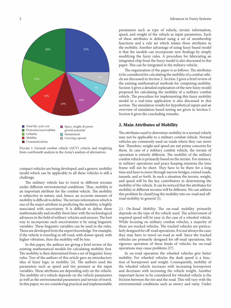
Recently there has been an increasing interest in variousaspects of combat vehicles Kempinski and Murphy stud-ied the technical challenges of ground combat vehicles in[1] Dattathreya and Singh discussed energy managementstrategies of combat vehicles in [2 3] Several authors haveshown interest in predicting the mobility of military vehicles[4ndash6] Mobility in general can be defined as the ability tomove or to be moved freely and easily Mobility in case of aground combat vehicle is defined as ldquovehiclersquos capability tomove over a specified terrain which is influenced by otherenvironmental conditions such as weatherrdquo [4] The basicfunction of a military combat vehicle is the transportation ofthe soldiers and weapons According to a recent research onthe costbenefit analysis for themilitary combat vehicle a 10weightage is given for mobility by the ground combat vehicleanalysis of alternatives [1] Other main attributes obtainedfrom the analysis are total life cost lethality survivability andso forth as given in [1] and shown in Figure 1
Mobility has a different definition when viewed from amilitary vehiclersquos perspective Such a definition in [7] forthe mobility of military vehicle is ldquothe ability to move freelyand rapidly over the terrain of interest to accomplish variedcombat objectivesrdquo From this definition mobility is the
freedom of movement in diverse terrains under differentenvironmental conditions Freedom of movement can bedefined as good speed less vibration and so forth A reportby Unger discusses several aspects ofmobility in [8]Mobilityassessment for the military vehicle is carried out in diverseterrains with different environmental conditions It is neces-sary to test the mobility of a vehicles before using it on thefieldThe conventional methods for definingmobility revolvearound puremathematicalmodeling Differentmathematicalmodels are available in the literature Studies by EngineeringResearch and Development Center (ERDC) treat mobilityas a function of trafficability [9] A modified mathematicalmodel based on trafficability studies for wheeled vehicles wasalso proposed in [10 11] A stochastic approach for predictingmobility is developed by Gonzalez et al [12] Mobility modelfor ground vehicles based on soil-moisture can be found in[13] An extended Kalman filter basedmobility estimation forunmanned ground vehicles is presented in [14] The tire-soilinteraction simulation based on absolute nodal coordinateformulation (ANCF) is developed by Recuero et al in [15]A physics-based simulation model is discussed in [16] Thisdeals with light tracked vehicles weigh less than 100 lb oper-ating on deformable terrains These complex mathematicalmodels focus on the effect of individual input attributes onthe mobility With the improvements in technology newer
HindawiAdvances in Fuzzy SystemsVolume 2017 Article ID 3982753 12 pageshttpsdoiorg10115520173982753
2 Advances in Fuzzy Systems
20 25
15
10
1010
5
5
Total life cycle costProtectionsurvivabilityLethalityMobilityCommunications
Space weight amp powergrowth potentialSustainmentCarrying capacity
Figure 1 Ground combat vehicle (GCV) criteria and weightingfrom costbenefit analysis in the Armyrsquos analysis of alternatives
compact vehicles are being developed and a generic mobilitymodel which can be applicable to all these vehicles is still achallenge
The military vehicle has to travel in different terrainsunder different environmental conditions Thus mobility isan important attribute for the combat vehicle The mobilityis subjective in nature and hence an accurate measure ofmobility is difficult to defineThe terrain informationwhich isone of the major attribute in predicting the mobility is highlyassociated with uncertainty It is difficult to define themmathematically andmodify them later with the technologicaladvances in the field ofmilitary vehicles and sensorsThe bestway to incorporate such uncertainties is by using linguisticvariables These linguistic variables can be used in the rulesThese are developed from the expert knowledge For exampleif the vehicle is traveling in off-road with slower speed withhigher vibration then the mobility will be less
In this paper the authors are giving a brief review of theexisting mathematical models for calculating mobility firstThemobility is then determined from a set of linguistic fuzzyrules Two of the authors of this article gave an introductoryidea of fuzzy logic in mobility [4] The authors used theparameters such as speed and tire pressure as the inputvariables These attributes are depending only on the vehicleThe mobility of a vehicle depends on the vehicle parametersas well as the environmental parameters and terrain of travelIn this paper we are considering practical and implementable
parameters such as type of vehicle terrain informationspeed and weight of the vehicle as input parameters Eachof these attributes is defined using a set of membershipfunctions and a rule set which relates these attributes tothe mobility Another advantage of using fuzzy based modelis that the models can incorporate new findings by simplymodifying the fuzzy rules A procedure for fabricating anintegrated chip from the fuzzy model is also discussed in thispaper This can be integrated in the military vehicle
The organization of the paper is as follows The attributesto be considered for calculating themobility of a combat vehi-cle are discussed in Section 2 Section 3 gives a brief review ofthe existing mathematical methods for computing mobilitySection 4 gives a detailed explanation of the new fuzzy modelproposed for calculating the mobility of a military combatvehicle The procedure for implementing this fuzzy mobilitymodel in a real-time application is also discussed in thissectionThe simulation results for hypothetical inputs and anoverview of simulation based testing are given in Section 5Section 6 gives the concluding remarks
2 Main Attributes of Mobility
The attributes used to determinemobility in a normal vehiclemay not be applicable to a military combat vehicle Normalvehicles are commonly used on roads where they can movefast Therefore weight and speed are not prime concerns forthem In case of a military combat vehicle the terrain ofoperation is entirely different The mobility of the militarycombat vehicle is primarily based on the terrain For instancein military operations and peace keeping missions the timeframe will not be short They have to be there for a longtime and have tomove through narrow bridges ruined roadstunnels and so forth In such a situation the terrain weightand speed will be the key contributors in determining themobility of the vehicle It can be noticed that the attributes formobility in different terrains will be differentWe can addressthis problem by classifying the mobility into on-road and off-road mobility in general [1]
21 On-Road Mobility The on-road mobility primarilydepends on the type of the vehicle used The achievement ofrequired speed will be easy in the case of a wheeled vehicleWhile focusing on military combat vehicles a majority ofthem are tracked vehicles The tracked vehicles are particu-larly designed for off-road operations It is not always the casethey may have to travel on-road as well Since the trackedvehicles are primarily designed for off-road operations therigorous operation of these kinds of vehicles for on-roadoperations may cause problems [17]
In on-road operation the wheeled vehicles give bettermobility For wheeled vehicles the dash speed is a func-tion of horsepower and weight Consequently mobility ofthe wheeled vehicle increases with increasing horsepowerand decreases with increasing the vehicle weight Anotherimportant factor to be considered for wheeled vehicle is thefriction between the tire and the roadThis will vary with theenvironmental conditions such as snowy and rainy Under
Advances in Fuzzy Systems 3
these circumstances the mobility of the wheeled vehicles willdecrease and thus a good choice will be the tracked vehicles
22 Off-Road Mobility For military operations off-roadmobility is essential A military vehicle is said to have goodmobility if it is having good off-road as well as on-roadmobility The military vehicles are constrained to travelthrough off-road in many operations This may be to avoidthe danger of IEDs planted on raod or sometimes there isno proper road at all The statistics shows that the casualty issevere by IEDs compared to other kinds of attacks [18] Thusa military vehicle has to travel off-road intensively
Compared to on-road mobility off-road mobility is verycomplex and depends upon a number of factors The mea-surability of these parameters is also challenging The weightof the vehicle is taken as an attribute for off-road mobilitybut not in a direct form Here the resistance of the surfaceis playing a vital role This resistance is related to the typeof surface and the ground pressure The ground pressure iscalculated as the ratio of gross weight of the vehicle to thesurface area of ground contact with the vehicle Another termused in literature to calculate off-roadmobility is vehicle coneindex (VCI) [7] VCI is a function of soil strength and vehicleground pressure Priddy and Willoughby [19] define VCI asldquothe minimum soil strength necessary for a self-propelledvehicle to consistently make a prescribed number of passesin track without becoming immobilizedrdquo
The ground pressure and VCI are having an inverserelationship with mobility Another important factor to beconsidered for computing the mobility of an off-road combatvehicle is the freedom of movement of the vehicle in thatparticular terrainThe freedom of movement depends on theminimum acceptable value of ground pressure or thresholdground pressure This value varies for different combat vehi-cles Another terminology given in literature is percentageno-go terrain [7] It is a measure of immobile terrain and canbe directly related to the ground pressure [20]
The tracked vehicles are preferred for off-road movementover wheeled vehicle as the tracked vehicles provide greatersurface area and consequently lesser ground pressure [21]For better off-road mobility there should be a higher horsepower to weight ratio low VCI low ground pressure andadvanced suspension system for the vehicle
3 Review of Mobility Models
There are different models available in the literature forpredicting the mobility of a combat vehicle Some of theseare used as simulation models while others are mathematicalmodels with complex equations Some of the popular modelsavailable in the literature are discussed in this section
31 Simulation Models The simulation model is useful tounderstand the performance of the vehicle in different ter-rains and other conditions It is always a good idea to test themobility in the simulationmodel with expected attributes fora particular kind of military vehicle The simulation models
differ from each other on the attributes they are using forcomputing the mobility
One of the most popular simulationmodels for analyzingmobility is NATO Reference Mobility Model (NRMM) [22]There are three modules associated with NRMM (1) vehicledynamic module (2) obstacle crossing performance moduleand (3) primary prediction module This model can predictthe mobility of a combat vehicle for both on-road and off-road operations The mobility is predicted as the effectivemaximum speed by analyzing different attributes The dis-advantage of NRMM is its limited range of operation Thismodel will not fit in complex terrains Lessem et al proposedNRMM adaptation to stochastic orientation [5] so that themodel can be used for high resolution combat zones In [15]a mobility simulation model based on tire flexibility anddeformation of terrains is presented This simulation modelis limited to wheeled vehicles A simulation model whichfocuses on small autonomous vehicles is discussed in [16]This simulation deals with the obstacles in the path of vehiclesand its impact on themobility of the light autonomous vehicleand can simulate different terrains such as flat rigid terrainand deformable terrain
The testing of simulation models can be performed bydeveloping a set of virtual operating conditions Such a frame-work is called Virtual Evaluation Test (VET) framework [6]Evaluation suites like VET can be used for many simulationmodels to study mobility stability durability and so forthThese frameworks evaluate the existing simulation modelsand provide a report on the progress of the model
32 Mathematical Models The Engineer Research and De-velopment Center (ERDC) defines vehicle cone index in twodifferent ways One is one-pass vehicle cone index (VCI
1) and
other is fifty-pass vehicle cone index (VCI50) [9]These values
are calculated from the vehicle attributes such as weight anddimensions by conducting multipass experiment and areexpressed in PSI [19] As discussed earlier the soil strengthis an important parameter for calculating mobility TheInternational Society for Terrain Vehicle Systems (ISTVS)defines VCI as the ldquominimum soil strength in the critical soillayer in terms of rating cone index for fine grained soils orin cone index for coarse grained soils required for a specificnumber of passes of a vehicle usually one pass (VCI
1) or
50 passes (VCI50)rdquo [23] VCI is a common parameter for
both on-road and off-road analysis hence it can be usedas a common parameter for defining mobility of all groundcombat vehicles
Other important factors used in the calculation of mobil-ity are the mobility index (MI) and deflection correctionfactor (DCF) [19] Combat vehicle mobility in soft soil terrainis defined by a parameter called ldquomean maximum pressure(MMP)rdquo MMP was developed by UK MODrsquos DefenceScience and Technology Laboratory (DSTL) [19] Accordingto this model the mobility is calculated from the groundcontact pressure MMP is calculated by taking the average ofmagnitudes of maximum pressure at each wheel ThereforeMMP is related to the dimensions of the wheel and also tothe weight of the vehicle
4 Advances in Fuzzy Systems
Modifications on original MMP calculations based onterrains and different sensors are discussed in [24ndash27] Anextensive review ofmathematicalmodeling ofmobility is bestgiven by Priddy andWilloughby in [19] Mobility index (MI)for wheeled vehicle is given in [19] as
MI = ((CPF) (WF)(TEF) (GF) +WLF minus CF) (EF) (TF) (1)
where CPF is the contact pressure factor WF is the weightfactor TEF is the traction element factor GF is the grouserfactorWLF is thewheel load factor CF is the clearance factorEF is the engine factor and TF is the transmission factor
Now CPF can be calculated as follows
CPF = 11990805119899119889119887 (2)
where 119899 is the average axle loading in lb 119899 is the averagenumber of tires per axle 119889 is the average tire outside diameter(inflated unloaded) in in and 119887 is the average tire sectionwidth (inflated unloaded) in in Similarly other parametersare given by
TEF = 10 + 119887100 WLF = 1199082000
CF = ℎ11988810
(3)
where ℎ119888is the vehicle minimum clearance height in in
GF = 1 + 005119888GF (4)
where 119888GF = 1 if tire chains are used or 0 if not
EF = 1 + 005119888EF (5)
where 119888EF = 1 if PWR lt 10 hpton or 0 if not
TF = 1 + 005119888TF (6)
where 119888TF = 1 if manual transmission or 0 if automatic
WF = 119888WF11199081000 + 119888WF2 (7)
where 119908 lt 2000 lb rArr 119888WF1 = 0553 and 119888WF2 = 0 2000 le119908 lt 13500 lb rArr 119888WF1 = 0033 and 119888WF2 = 1050 13500 le119908 lt 20000 lb rArr 119888WF1 = 0142 and 119888WF2 = minus0420 20000 le119908 lt 31500 lb rArr 119888WF1 = 0278 and 119888WF2 = minus3115 31500 le119908 rArr 119888WF1 = 0836 and 119888WF2 = minus20686A deflection correction factor (DCF) is required to
account the effect of tire deflection on VCI performance [19]
DCF = (015120575ℎ )025
(8)
where 120575 is the average hard-surface tire deflection expressedin in and ℎ is the average tire section height (inflatedunloaded) in in
The analysis and test data of different vehicles underdifferent environments were studied Based on the past 50yearsrsquo data the researchers came up with an expression inwhich the VCI
1is a function of MI and DCF [19]
MI le 115 997904rArr
VCI1= (1148 + 02MI minus 392
MI + 374)DCFMI gt 115 997904rArrVCI1= (41MI0446)DCF
(9)
A stochastic model which relates the geometry of the surfaceand soil type to the mobility map was proposed by Gonzalezet al in [12] The mobility map produced in this modelshows the surface elevation at each location In [13] theeffect of soil-moisture on the off-road mobility is studiedbased on satellite soil-moisture data It is found that thetype of vehicle the environmental conditions and so forthwill significantly vary the soil-moisture and thus the off-road mobility Another approach for mobility estimation ofunmanned ground vehicle which uses a Gauss-Markov statespace dynamic model and a first-order semi-Markov modelalong with an extended Kalman Filter is discussed in [14]This approach can give a real-time path planning for theunmanned ground vehicle
4 Proposed Method
Mobility models explained in Section 3 consist of very com-plexmathematical equationsThemodification of thesemod-els is very difficult and cumbersome Mobility is subjectiveand depends on the user comfortableness A fuzzy basedmodel gives the freedom for the designer to improve themodel without much effort by taking feedback from the user
41 Fuzzy Logic Outline Fuzzy logic is a technique whichuses the degree of truth instead of discrete values such as0 or 1 Fuzzy logic also uses ldquolinguisticrdquo variables such aslow medium and high along with numerical variables forthe calculationsThe relationship between inputs and outputsis given by some simple statements rather than complexmathematical equations [28] Fuzzy based systems are widelyused in many real-time applications [29]
Let 119860 be a fuzzy subset We can represent 119860 as119860 = 120583119910 (10)
where 120583 is the degree of membership of 119910 in fuzzy subset119860 If 119860 is having more number of membership functionsassociated with it then 119860 can be represented as
119860 =119873
sum119894=1
120583119894
119910119894
(11)
where 120583119894is the degree of membership of corresponding
119910119894in 119860 Here the + sign indicates the union of different
Advances in Fuzzy Systems 5
10
0x0 x1 x2
x
(x
)
Figure 2 Triangular membership function
memberships The membership degree is having a valuebetween 0 and 1 For a fuzzy subset 119860120583 (119909) = 0 if 119909 notin 119860120583 (119909) = 1 if 119909 isin 119860120583 (119909) isin (0 1) if 119909 possibly in 119860 but not sure
(12)
There are different types of membership functions avail-able in Fuzzy Triangular function and Gaussian distributionfunction and so forth are some of the commonly usedmembership functions A triangular membership function isshown in Figure 2 The degree of the membership function120583(119909) is given by
120583 =
0 if 119909 le 1199090
119909 minus 1199090
1199091minus 1199090
if 1199090le 119909 le 119909
1
1199092minus 1199091199092minus 1199091
if 1199091le 119909 le 119909
2
0 if 1199092le 119909
(13)
42 Fuzzy Mobility Model The block diagram of the pro-posed fuzzy mobility assessment model is shown in Figure 3The proposed scheme consists of three parts The first is theinput section The inputs can be analog signals directly fromthe sensors such as speed and weight of the vehicle in theproposedmethodTheother inputs are vehicle and the terraintypes The data is either preset or entered manually by theoperator
The second part of the proposedmethod is the fuzzy logiccontrollerThe fuzzy logic controller consists of four differentsections The first section is a fuzzifier The fuzzifier convertsthe numerical value obtained from the input signal into fuzzysets That is the input variables are represented in termsof their degree of membership for different membershipfunctions The second section is a rule base The rule basecontains all the rules for the fuzzymodelThe rules use if-thenstructure to relate the input fuzzy sets with the output fuzzysets The third section is an inference engine The inferenceengine takes the input fuzzy sets and decides which rules
Table 1 Linguistic parameters for the weight variable
Weight in lb Linguistic parameter10000ndash30000 Low30000ndash50000 Medium50000ndash70000 High
Table 2 Linguistic parameters for the speed variable
Speed in mph Linguistic parameter0ndash20 Low20ndash40 Medium40ndash60 High
Table 3 Input and output variables for fuzzy model
Input variables Output variableTerrain Vehicle type Weight Speed MobilityDry Wheel Low Low LowWet Track Medium Medium MediumLowSnow High High MediumSand MediumHigh
High
should be applicable from the rule base and creates the outputfuzzy setThe last section is a defuzzifierwhich takes the fuzzyset output created by the inference engine and produce thecorresponding output
The fuzzifier consists of membership functions Themembership functions are expressed using linguistic parame-ters Important attributes considered for calculating mobilityof themilitary vehicle are type of vehicle terrain informationspeed of the vehicle and the weight of the vehicle Theweight and speed of the vehicle are numerical valuesThey areconverted to linguistic parameters such as low medium andhigh In the proposed example the weight of a vehicle variesbetween 10000 and 70000 lbThis range is divided into threesections The linguistic parameters for the weight are shownin the Table 1
Linguistic parameters for the speed are defined in Table 2In this case the normal range is from 0 to 60mph Likewisethe membership functions for the mobility of the militaryvehicle are also expressed by 5 different linguistic param-eters The input and output linguistic variables used forthe proposed fuzzy model can be summarized as shown inTable 3Different types ofmembership functions are availablein fuzzifier A trigonometric membership function is usedfor the proposed model The arrangement of membershipfunctions for the speed of military vehicle and normalizedmobility output is shown in Figures 4 and 5 respectivelyThefuzzifier converts the numerical value of input to fuzzy setwhich is a set of membership function and correspondingdegree of membership For example if the speed is 26mphthen the fuzzifier will represent it by low with a degree of 02
6 Advances in Fuzzy Systems
Type ofvehicle
Terraininformation
Speed ofthe vehicle
Weight ofthe vehicle
Fuzzifier
Rules
Inferenceengine
Defuzzifier Mobility
Figure 3 Block diagram of the proposed mobility assessment method
Low1
08
Medium High
0
02
04
06
Deg
ree o
f mem
bers
hip
0 10 20 30 40 50 6026
Speed (mph)
Figure 4 Speed input variable partitions using triangular functions
Low1
08
MediumLow Medium MediumHigh High
0
02
04
06
Deg
ree o
f mem
bers
hip
01 02 03 04 05 06 07 08 1090
Normalized mobility
Figure 5 Military vehicle mobility variable partitions using trian-gular functions
and medium with a degree of 08 and high with a degree ofzero
After studying the characteristics of the military vehiclemobility defined by different mathematical models it ispossible to define a set of approximate rules for the mobilityassessment The linguistic parameters are used in derivingappropriate rules for the proposed fuzzy logic model Theserules are made up of simple logic employing IF AND OR
and NOT operators The mobility output is categorized asLow MediumLow Medium MediumHigh andHigh In otherwords the input and output parameters of the proposedmodels are fuzzy setsThe rules used to calculate the mobilityare simple sentences with some logical expressions The listof all the rules used in the fuzzy logic model is listed inTable 4 Here each input membership function is connectedwith AND statement Such as the following
(i) If terrain is dry and vehicle type iswheel and weight ishigh and speed is low then mobility is low
(ii) If terrain is dry and vehicle type iswheel and weight islow and speed is high then mobility is high
For each input combination the mobility output is definedusing these rules The inference engine selects the rules thatare applicable for the input values and produce the corre-sponding output fuzzy set The fuzzy set is then convertedto a crisp value by a defuzzifier The surface diagram ofthe mobility output with respect to different set of inputsis given in Figure 6 The simulation of such a fuzzy modelcan be tested using Matlab simulation The military vehiclemobility output obtained in such a simulation will also be ina normalized form
After the simulation the fuzzy rules can be convertedto a Verilog code This is simple and straightforward TheVerilog program can be written in a behavioral level withif statements The linguistic parameters used in the fuzzyrules are converted to digital numbers while writing theVerilog code For instance the speed input variable linguisticparameters low medium and high can be converted to 00 01and 10 respectively
After completing the Verilog code it should be testedwith some tools The simulation and hardware testing for thecode are possible The simulation of the Verilog code can bedone using Cadence NClaunch or some other software whichcan do the simulation For hardware testing the Verilog codecan be implemented on an FPGA If both the simulation andhardware results are satisfactory the next step is to design thefuzzy chip using this Verilog code
Advances in Fuzzy Systems 7
07
06
05
04
03
02
11
0505
00
Mob
ility
06
05
04
03
Mob
ility
06
05
04
03Mob
ility
02
06
05
04
03Mob
ility
06
05
04
03
Mob
ility
06
05
04
03
Mob
ility
Veh type
1
11
1
05
0505
05
0
00
0
Veh type
Veh type
Terrain
Terrain
Terrain
24
6
Weight
24
6
Weight
times104
times104
24
6
Weight times104
60
40
20
0Speed
60
40
20
0Speed
60
40
20
0Speed
Figure 6 Surface plot obtained for different set of inputs (vehicle type-terrain vehicle type-weight vehicle type-speed terrain-weight terrain-speed and weight-speed) versus mobility
For building the chip from the Verilog code the first stepis to convert the behavioral level code to a netlist or gatelevel code This can be done by Cadence synthesizer Aftercompleting the gate level code a layout for the circuit canbe produced using Cadence Encounter The Encounter usessome standard cell libraries to complete the layout Once thelayout is ready the next step is to do the padding for thechip A Cadence Virtuoso software is used for this purpose
After completing the padding the design can be sent to themanufacturer to fabricate the final chip The process flowchart for the proposed scheme is shown in Figure 7
Once the chip is ready to use it can be installed in themilitary vehicle and the mobility output can be displayedto the driver in a range of 0 to 100 The inputs for thechip can be from a sensor and the output can be displayedinside the vehicle which is shown in Figure 8 [30] For a
8 Advances in Fuzzy Systems
Table 4 Fuzzy logic rule set
Terrain Veh type Weight Speed MobilityDry Wheel Low Low LowDry Wheel Low Medium MediumHighDry Wheel Low High HighDry Wheel Medium Low MediumLowDry Wheel Medium Medium MediumHighDry Wheel Medium High HighDry Wheel High Low LowDry Wheel High Medium MediumHighDry Wheel High High HighDry Track Low Low MediumLowDry Track Low Medium MediumDry Track Low High MediumHighDry Track Medium Low LowDry Track Medium Medium MediumLowDry Track Medium High MediumDry Track High Low LowDry Track High Medium MediumLowDry Track High High MediumLowWet Wheel Low Low LowWet Wheel Low Medium MediumWet Wheel Low High MediumHighWet Wheel Medium Low MediumLowWet Wheel Medium Medium MediumHighWet Wheel Medium High MediumHighWet Wheel High Low LowWet Wheel High Medium MediumWet Wheel High High MediumHighWet Track Low Low MediumLowWet Track Low Medium MediumHighWet Track Low High MediumHighWet Track Medium Low LowWet Track Medium Medium MediumLowWet Track Medium High MediumWet Track High Low LowWet Track High Medium MediumLowWet Track High High MediumSnow Wheel Low Low LowSnow Wheel Low Medium MediumLowSnow Wheel Low High MediumSnow Wheel Medium Low LowSnow Wheel Medium Medium MediumLowSnow Wheel Medium High MediumSnow Wheel High Low MediumLowSnow Wheel High Medium MediumSnow Wheel High High MediumHighSnow Track Low Low MediumLowSnow Track Low Medium MediumSnow Track Low High MediumHighSnow Track Medium Low LowSnow Track Medium Medium MediumLowSnow Track Medium High Medium
Advances in Fuzzy Systems 9
Table 4 Continued
Terrain Veh type Weight Speed MobilitySnow Track High Low LowSnow Track High Medium MediumLowSnow Track High High MediumLowSand Wheel Low Low MediumLowSand Wheel Low Medium MediumSand Wheel Low High MediumHighSand Wheel Medium Low MediumLowSand Wheel Medium Medium MediumLowSand Wheel Medium High MediumSand Wheel High Low LowSand Wheel High Medium MediumLowSand Wheel High High MediumSand Track Low Low MediumLowSand Track Low Medium MediumSand Track Low High MediumHighSand Track Medium Low LowSand Track Medium Medium MediumLowSand Track Medium High MediumSand Track High Low LowSand Track High Medium MediumLowSand Track High High MediumLow
Table 5 Simulation results of fuzzy mobility model
Terrain Veh type Weight Speed MobilitySnow Track 30000 20 03617Sand Track 30000 40 04782Dry Wheel 50000 50 08089Wet Wheel 70000 20 04077Dry Wheel 20000 60 09139Sand Wheel 50000 40 03568Dry Track 25000 45 05469
given operational scenario the parameters of the vehicleare constant However the speed terrain and weight mayvary depending on a mission The fuzzy electronic chip canestimate instantaneous mobility of the military vehicle anddisplay it on the vehicle
5 Testing of the Fuzzy Based Method
The simulation of the proposed fuzzy mobility model inMatlab is carried out with different set of input combinationsThe results are given in Table 5 Furthermore the simulationof the proposed method is done by setting the weight of thevehicle to 30000 lb and varying the speed from 0 to 50mphThe mobility of the vehicle is plotted under different terrainswith track and wheel vehicle The graph is shown in Figure 9
The validation of the results can be done in different waysOne way of testing is by comparing the simulation modelwith user data obtained from similar real life experienceTheproposedmethod can be verified by taking the feedback fromvehicle users Their feedbacks can be used to optimize themodel by comparing the user data with the outputs of thefuzzy model for the same set of inputs
In the second method the human factor is introduced inpredicting the mobility of a vehicle The block diagram of thesimulation model is given in Figure 10 This diagram showsthe flow of mobility prediction from the visual informationof a vehicle mobility in a computer simulation The differentattributes that decide the mobility are given as input to thecomputer model and the computer model gives simulationdisplay where the given type of vehicle moves through aparticular terrain with specific weight and speed
51 Overview of Simulation Based Testing The cost formaking hardware is massive To improve the accuracy ofthe hardware more emphasis should be given to modelingand simulation For the simulation based testing Autonomiesoftware can be used [31]This software has a large database ofvehicles and these data can be used to make the simulationmore effective Autonomy helps to simulate the model withplug-and-play functionalities The models built in standardformat can be added to the autonomy software for simulationThe library and tested models available with the softwarepackage make the simulation more accurate
10 Advances in Fuzzy Systems
Define fuzzy rules
Implement the logic in Matlab
Convert fuzzy rules tohardware description language(eg Verilog)
Test Verilog code using FPGA Modify the rules
If rulesare OK
False
True
Build gate level program
Design placing and routing layout
Timing and design rules check
Finalize chip assembly
Implement the design in VLSI
Figure 7 Flowchart showing the design of proposed fuzzy modelchip
The algorithm for testing the the fuzzy model can besummarized as follows
(i) The Simulink software can be used to create thesimulation of the vehicle by using the proposed fuzzymodel This simulation model can be converted to119878 function which can be used in the Autonomiesoftware
(ii) Some signal formatting is necessary while integrat-ing the simulation 119878 function with the Autonomiesoftware Some of the vehicle parameters are alreadyavailable in the Autonomie software and the 119904-function can use these input variables
(iii) Interface themodified 119904-functionwith theAutonomiesoftware The Autonomie software has the abilityto identify the 119904-function parameters Normally theinput and output variables used with the 119904-functionmay not be documented in the standard format TheAutonomie converts these into a standard format andensures compatibility of input output variables withthe rest of the vehicle Instead of 119904-function it is also
Mobility indicator andgraph
Fuzzy chip
Weight sensors
Speed sensors
Figure 8 Diagram showing the position of sensors and displays ina military vehicle
possible to use the vehicle simulation programs suchas TruckSim
(iv) Run the simulation with a set of input data Forexample the performance can be testedwith a trackedvehicle in a snow terrain with a medium weightand medium speed The simulation is repeated withdifferent set of inputs
(v) For each simulation let the vehicle users view the sim-ulation and take their comments on vehicle mobilityThemobility can be described in linguistic parameterssuch as LowMediumLowMediumMediumHigh andHigh
(vi) From the set of inputs getting from the vehicle userscompute a correlation between the mobility dataprovided by the vehicle user with the data calculatedby the fuzzy chip
(vii) Change the rules of the fuzzy model if required andrepeat the experiment to achieve optimum results
6 Conclusion
In this paper the existingmobilitymodels ofmilitary vehiclesare reviewed These methods use complex mathematicalequations and hence are difficult to adapt A fuzzy basedmobility assessment model is developed here Differentattributes which affect the mobility such as terrain vehicletype speed and weigh of the vehicle were taken as inputsMobility is defined in a range from 0 to 100 The fuzzymobility assessment model is simulated with different inputcombinationsThe implementation of the proposed model inan integrated chip is discussed The algorithm for testing theproposed fuzzy model is presentedThe fuzzy based mobilitymodel gives the designer the freedom to optimize the modelwithout much effort by taking feedback from the user Thepaper essentially describes an approachwhich can possibly beused for developing a chip to access the mobility of military
Advances in Fuzzy Systems 11
0 5 10 15 20 25 30 35 40 45 50Speed (mph)
TrackWheel
02
03
04
Mob
ility
05
06
07
08
09
(a)
0 5 10 15 20 25 30 35 40 45 50Speed (mph)
TrackWheel
02
025
03
035
04
Mob
ility
045
05
055
06
065
(b)
0 5 10 15 20 25 30 35 40 45 50Speed (mph)
TrackWheel
01
015
02
025
03
035
Mob
ility
04
045
05
055
06
(c)
0 5 10 15 20 25 30 35 40 45 50Speed (mph)
TrackWheel
02
025
03
035
04
Mob
ility
045
05
055
(d)
Figure 9 Speed versus mobility graph for track and wheel vehicles with weight = 30000 lb in different terrains (a) dry (b) wet (c) snowand (d) sand
Inputs (weightspeed terraintype of vehicle)
Simulation of vehiclemovement in the terrainselected
Human visualsystem
Predicting themobility of thevehicle
Figure 10 Block diagram showing the testing of the proposed method
vehicle More work is needed to modify the model so as toimplement a real life chip which would be used ultimately inthe military vehicle
Disclosure
Unclassified Distribution Statement A Approved for publicrelease distribution is unlimited
Conflicts of Interest
The authors declare that there are no conflicts of interestregarding the publication of this article
Acknowledgments
This work is supported by TARDEC Grant
12 Advances in Fuzzy Systems
References
[1] B Kempinski and C Murphy ldquoTechnical challenges of the usarmys ground combat vehicle programrdquo Tech Rep 2012
[2] M S Dattathreya and H Singh ldquoMission aware energy effi-ciency in stationary combat vehiclesrdquo IEEE Transactions onAerospace and Electronic Systems vol 50 no 2 pp 1108ndash11172014
[3] M S Dattathreya and H Singh ldquoSilent-watch and energymanagement strategy in combat vehiclesrdquo IEEE Transactions onAerospace and Electronic Systems vol 50 no 1 pp 418ndash4282014
[4] M S Dattathreya and H Singh ldquoA novel approach for combatvehicle mobility definition and assessmentrdquo SAE TechnicalPapers 2012
[5] A Lessem G Mason and R Ahlvin ldquoStochastic vehiclemobility forecasts using the NATO reference mobility modelrdquoJournal of Terramechanics vol 33 no 6 pp 273ndash280 1996
[6] P Nunez A Reid R Jones and S Shoop ldquoA virtual evaluationsuite for military ground vehicle dynamic performance andmobilityrdquo SAE Technical Papers 2002
[7] P Hornback ldquoThe wheel versus track dilemmardquo Armor Maga-zine vol 26 pp 33-34 1998
[8] R F Unger ldquoMobility analysis for the TRADOC wheeledversus tracked vehicle studyrdquo in US Army Engineer WaterwaysExperiment Station 1988
[9] ldquoTrafficability of soils vehicle classificationrdquo Tech Rep NinthSupplement US Army Engineer Waterways Experiment Sta-tion Vicksburg May 1951
[10] J S Kennedy andE S Rush ldquoTrafficability of soils developmentof revised mobility index formula for self-propelled wheeledvehicles in fine-grained soilsrdquo Tech Rep Eighteenth Sup-plement US Army Engineer Waterways Experiment StationVicksburg M S March 1968
[11] B G Schreiner ldquoComments on the VCI system unpublishedmemorandum for recordsrdquo US Army Engineer WaterwaysExperiment 1994
[12] R Gonzalez P Jayakumar and K Iagnemma ldquoStochasticmobility prediction of ground vehicles over large spatialregions a geostatistical approachrdquo Autonomous Robots vol 41no 2 pp 311ndash331 2017
[13] M T Stevens G BMcKinley and F Vahedifard ldquoA comparisonof ground vehicle mobility analysis based on soil moisture timeseries datasets from WindSat LIS and in situ sensorsrdquo Journalof Terramechanics vol 65 pp 49ndash59 2016
[14] P Thulasiraman G A Clark and T M Beach ldquoMobility esti-mation using an extended Kalman filter for unmanned groundvehicle networksrdquo in Proceedings of the 2014 IEEE InternationalInter-Disciplinary Conference on Cognitive Methods in SituationAwareness and Decision Support CogSIMA 2014 pp 223ndash229San Antonio TX USA March 2014
[15] A Recuero R Serban B Peterson H Sugiyama P Jayakumarand D Negrut ldquoA high-fidelity approach for vehicle mobilitysimulation Nonlinear finite element tires operating on granularmaterialrdquo Journal of Terramechanics vol 72 pp 39ndash54 2017
[16] D Negrut D Melanz H Mazhar D Lamb P Jayakumarand M Letherwood ldquoInvestigating Through Simulation theMobility of Light Tracked Vehicles Operating on DiscreteGranular Terrainrdquo SAE International Journal of Passenger Cars- Mechanical Systems vol 6 no 1 pp 369ndash381 2013
[17] Family of medium tactical vehicles (fmtv) 2015 httpwwwdoteosdmilpubreportsFY1999army99fmtvhtml
[18] ldquoHow the IED changed the US militaryrdquo USA Today 2015httpwwwusatodaycomstorynewsnation20131218ied-10-years-blast-wounds-amputations
[19] J D Priddy andW EWilloughby ldquoClarification of vehicle coneindex with reference to mean maximum pressurerdquo Journal ofTerramechanics vol 43 no 2 pp 85ndash96 2006
[20] J Wong and W Huang ldquoldquowheels vs tracksrdquomdasha fundamentalevaluation from the traction perspectiverdquo Journal of Terrame-chanics vol 43 no 1 pp 27ndash42 2006
[21] Wheeled versus track vehicle study final report Studies andAnalysis Activity Headquarters US Army Training and Doc-trine Command
[22] P W Haley M Jurkat and P Brady ldquoNato reference mobilitymodel edition 1 users guide US Army Tank-AutomotiveResearch and Development Commandrdquo Techn Rep vol no12503 1979
[23] M P Meyer I R Ehrlich D Sloss N Murphy R D Wismerand T Czako ldquoInternational society for terrain-vehicle systemsstandardsrdquo Journal of Terramechanics vol 14 no 3 pp 153ndash1821977
[24] J C Larminie ldquoModifications to the mean maximum pressuresystemrdquo Journal of Terramechanics vol 29 no 2 pp 239ndash2551992
[25] D Freitag ldquoA dimensional analysis of the performance ofpneumatic tires on clayrdquo Journal of Terramechanics vol 3 no3 pp 51ndash68 1966
[26] E Maclaurin ldquoProposed revisions to mmp based on the resultsof tractive performance trials with single pneumatic tyres anda modular track systemrdquo DERALS4TR97012210 DefenceEvaluation and Research Agency 1997
[27] D Rowland ldquoTracked vehicle ground pressure and its effect onsoft ground performancerdquo in Proceedings of the Proc 4th IntConf of Int Soc 1972
[28] L A Zadeh ldquoOutline of a New Approach to the Analysis ofComplex Systems and Decision Processesrdquo IEEE Transactionson Systems Man and Cybernetics vol 3 no 1 pp 28ndash44 1973
[29] H Singh M M Gupta T Meitzler et al ldquoReal-life applicationsof fuzzy logicrdquo Advances in Fuzzy Systems vol 2013 Article ID581879 3 pages 2013
[30] ldquo8th americas regional conference detroitrdquo in Proceedings of theUSA - 12-14 september pp 12ndash14 2016 httpconferenceistvsorgdetroit-military57u1cdctmnjaxge0be6fkan9xrzsot
[31] R Vijayagopal L Michaels A P Rousseau S Halbach and NShidore ldquoAutomated model based design process to evaluateadvanced component technologiesrdquo SAETechnical Papers 2010
Submit your manuscripts athttpswwwhindawicom
Computer Games Technology
International Journal of
Hindawi Publishing Corporationhttpwwwhindawicom Volume 2014
Hindawi Publishing Corporationhttpwwwhindawicom Volume 2014
Distributed Sensor Networks
International Journal of
Advances in
FuzzySystems
Hindawi Publishing Corporationhttpwwwhindawicom
Volume 2014
International Journal of
ReconfigurableComputing
Hindawi Publishing Corporation httpwwwhindawicom Volume 2014
Hindawi Publishing Corporationhttpwwwhindawicom Volume 201
Applied Computational Intelligence and Soft Computing
thinspAdvancesthinspinthinsp
Artificial Intelligence
HindawithinspPublishingthinspCorporationhttpwwwhindawicom Volumethinsp2014
Advances inSoftware EngineeringHindawi Publishing Corporationhttpwwwhindawicom Volume 2014
Hindawi Publishing Corporationhttpwwwhindawicom Volume 2014
Electrical and Computer Engineering
Journal of
Hindawi Publishing Corporation
httpwwwhindawicom Volume 2014
Advances in
Multimedia
International Journal of
Biomedical Imaging
Hindawi Publishing Corporationhttpwwwhindawicom Volume 2014
Advances in
Hindawi Publishing Corporationhttpwwwhindawicom Volume 201
RoboticsJournal of
Hindawi Publishing Corporationhttpwwwhindawicom Volume 2014
Hindawi Publishing Corporationhttpwwwhindawicom Volume 2014
Computational Intelligence and Neuroscience
Industrial EngineeringJournal of
Hindawi Publishing Corporationhttpwwwhindawicom Volume 2014
Modelling amp Simulation in EngineeringHindawi Publishing Corporation httpwwwhindawicom Volume 2014
The Scientific World JournalHindawi Publishing Corporation httpwwwhindawicom Volume 2014
Hindawi Publishing Corporationhttpwwwhindawicom Volume 2014
Human-ComputerInteraction
Advances in
Computer EngineeringAdvances in
Hindawi Publishing Corporationhttpwwwhindawicom Volume 2014
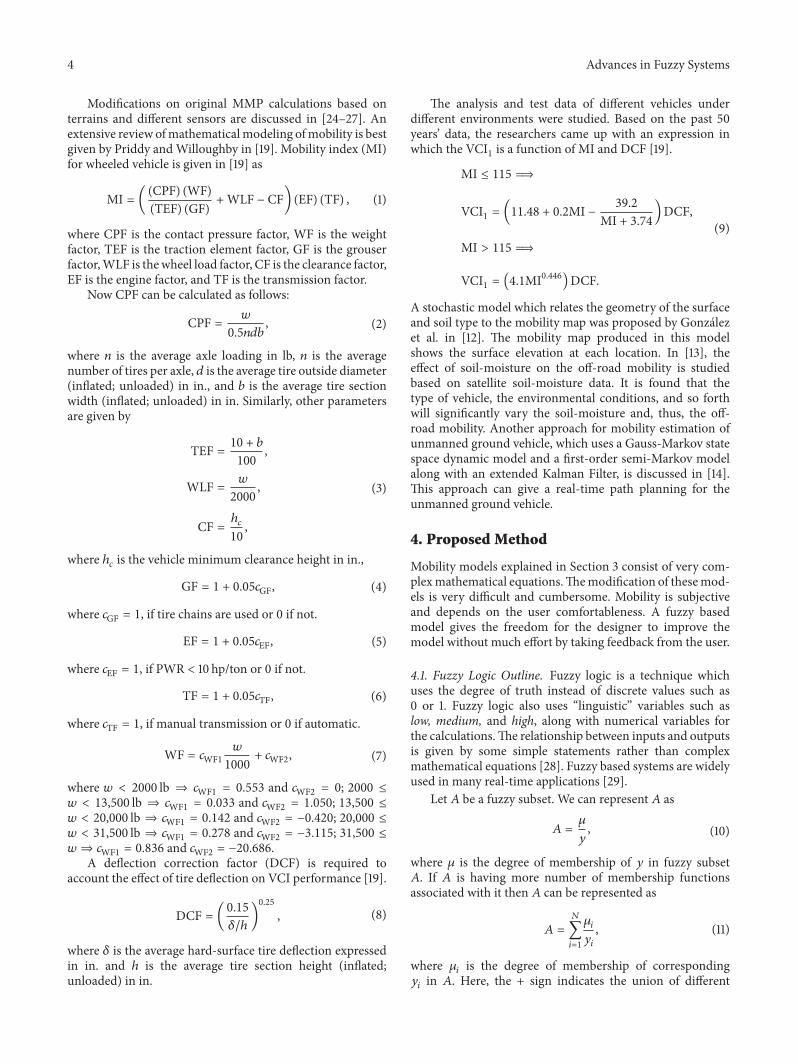
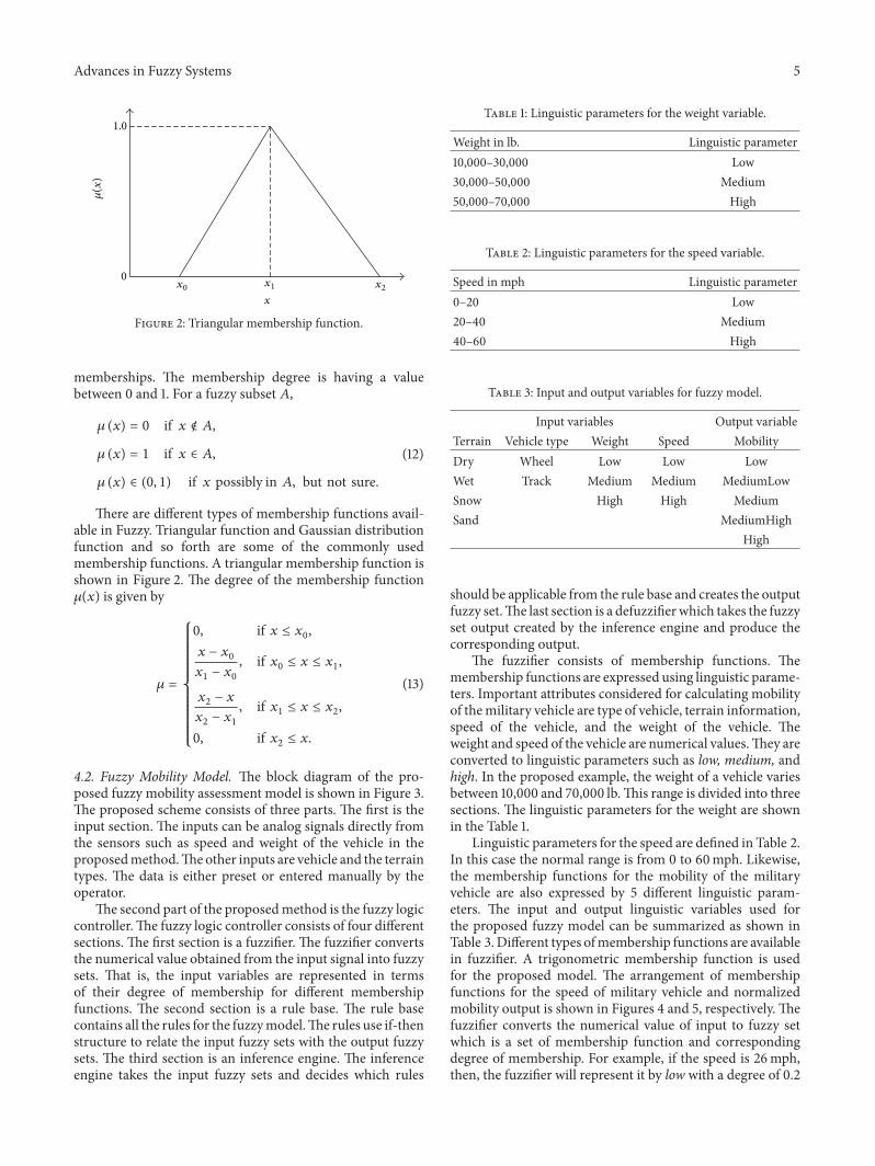
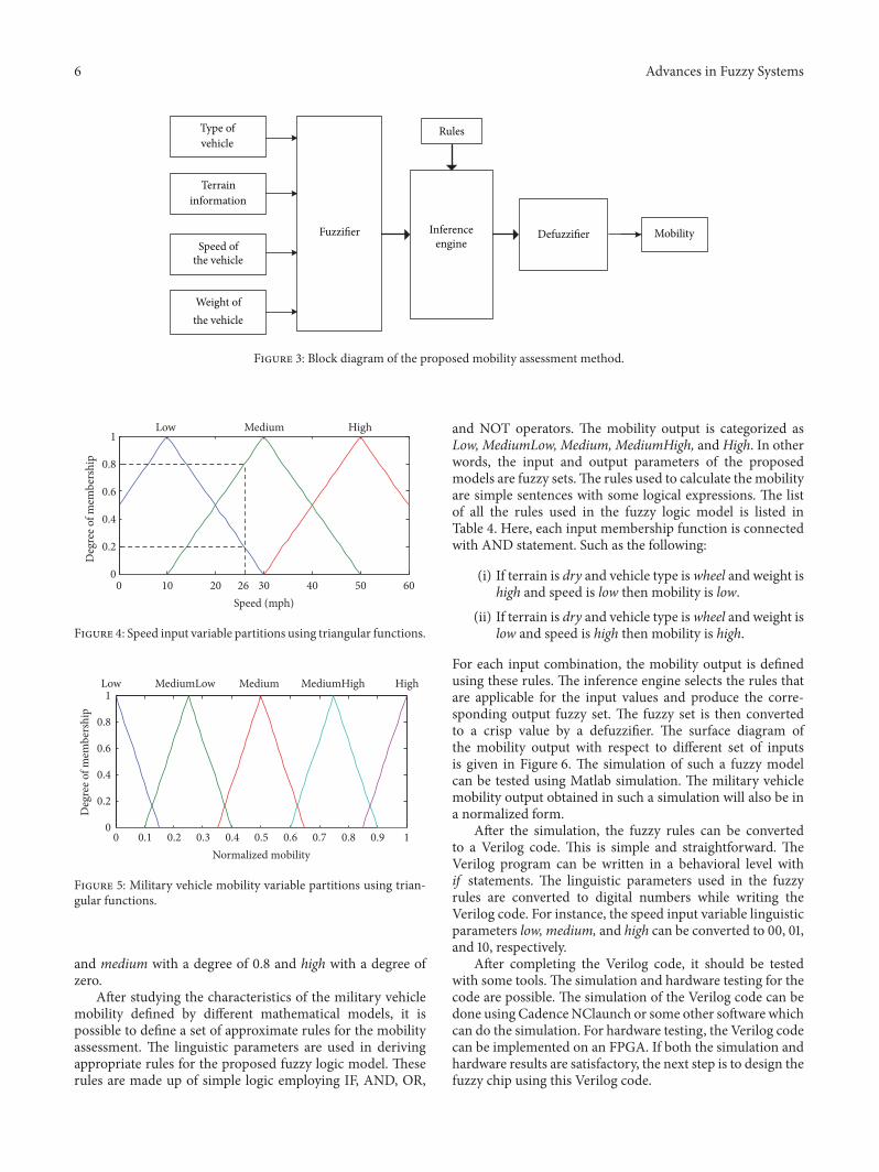
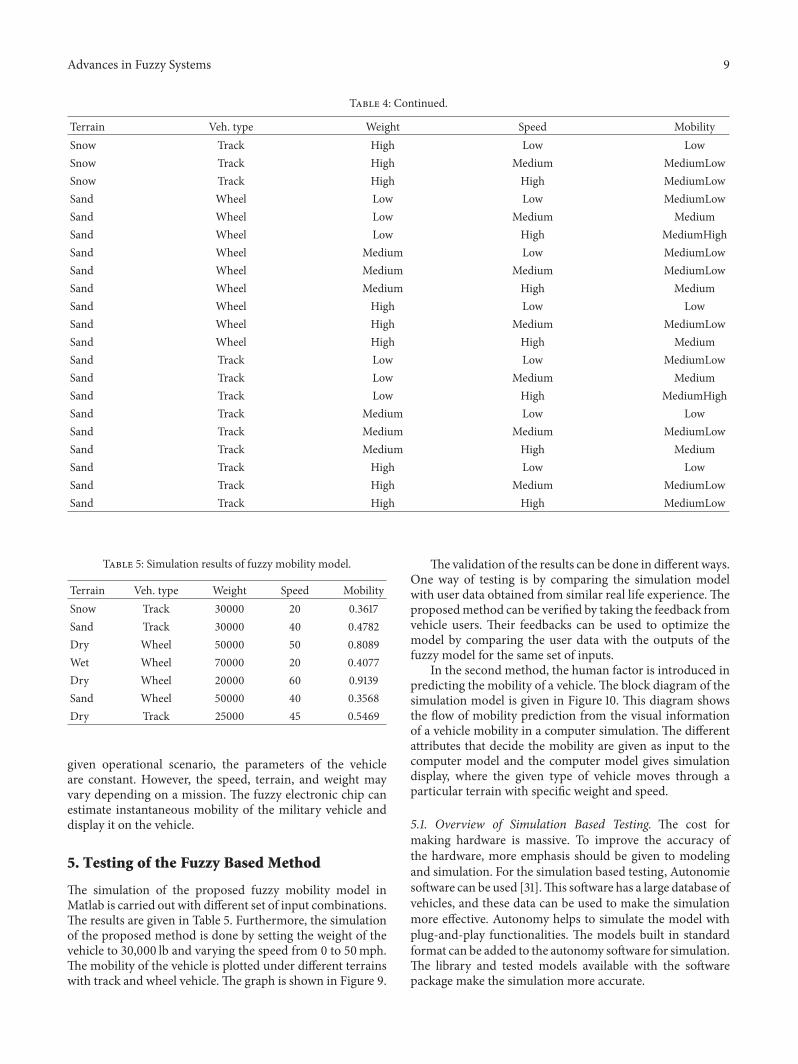
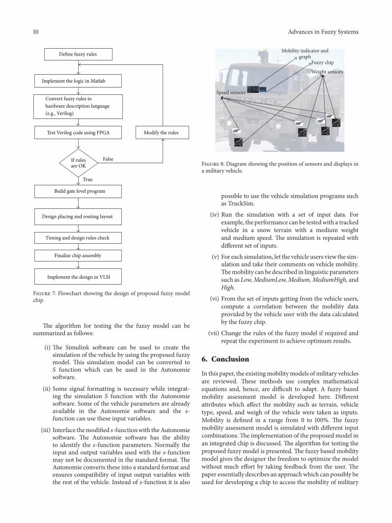
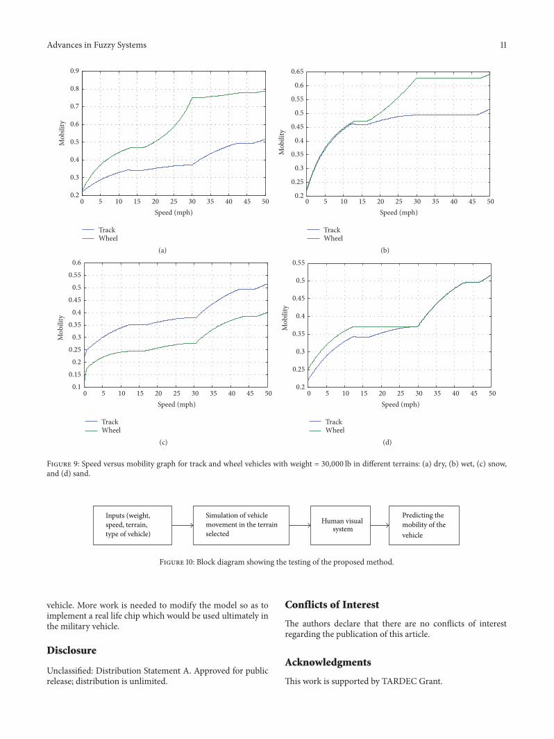
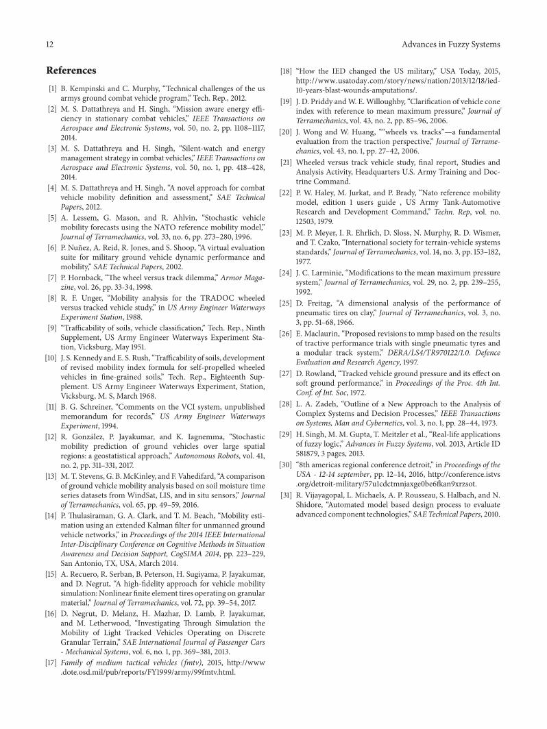