A Fuzzy Backstepping Control of a Mobile Manipulator with Torque Limits Avoidance · 2012-06-08 ·...
7
A Fuzzy Backstepping Control of a Mobile Manipulator with Torque Limits Avoidance 127 A Fuzzy Backstepping Control of a Mobile Manipulator with Torque Limits Avoidance Mohamed Boukattaya 1 , Tarak Damak 2 , and Mohamed Jallouli 3 , Non-members ABSTRACT In this paper, we present a dynamic redundancy resolution technique for mobile manipulator subject to joint torque limits. First, the dynamic model of the mobile manipulator in feasible motion space is given. Next, a control algorithm is proposed which completely decouples the motion of the system into the end-effector motion in the task space and an in- ternal motion in the null space and controls them in prioritized basis with priority given to the primary task space and enables the selection of characteris- tics in both subspaces separately. A special attention is given to the joints torque limits avoidance where a new weighted pseudo-inverse of the Jacobian that accounts for both inertia and torque limits is pro- posed to solve problems inherent to torque limits of the system. Simulation results are given to illustrate the coordination of two subsystems in executing the desired trajectory without violating the joint torque limits. Keywords: Mobile Manipulators, Dynamic Redun- dancy Resolution, Torque Limits, Task Space, Null Space 1. INTRODUCTION A mobile manipulator refers to the mobile system that has a mobile platform carrying a robotic ma- nipulator. Such systems combine the advantages of mobile platforms and robotic arms to reduce their drawbacks. For instance, the mobile platform ex- tends the arm workspace, whereas an arm offers much operational functionality. Applications for such sys- tems could be found in mining, construction, forestry, planetary exploration, and people assistance [1, 2, 3]. The combined system introduces new issues that are not present in the analysis of each subsystem con- sidered separately. First, the dynamics of the com- bined system are much more complicated because they include dynamic interactions between mobile Manuscript received on June 17, 2011 ; revised on September 1, 2011. 1,2 The authors are with Laboratory of Sciences and Tech- niques of Automatic control & computer engineering (Lab- STA), National School of Engineering of Sfax, University of Sfax. Postal Box 1173, 3038 Sfax, Tunisia, Email: mo- [email protected] and [email protected] 3 The author is with Laboratory of Computer Embedded Systems (CES) National School of Engineering of Sfax, Uni- versity of Sfax. Postal Box 1173, 3038 Sfax, Tunisia, Email: [email protected] platform and manipulator. Second, due to complex structure of the mobile manipulator, the constraints which are valid only for one subsystem will also hold for the whole mobile manipulator. Third, combining the mobility of the base platform and the manipu- lator creates redundancy since the combined system typically possesses more degrees of freedom than nec- essary. Most of the redundancy resolution methods in the literature have a principal underlying theme of opti- mizing a measure performance based on the kinemat- ics of the system. Several of these results have been extended and applied to mobile manipulators. For ex- ample, Seraji [4] proposes an approach to motion con- trol of mobile manipulators which incorporates the nonholonomic base constraints directly into the task formulation as kinematic constraints and thus treats the base nonholonomy and kinematic redundancy in a unified manner. Yamamoto and Yun [5] decompose the motions of the mobile manipulator into decou- pled base and manipulator subsystems. The base is then controlled so as to bring the manipulator to a preferred configuration (using criteria such as the ma- nipulability measure) as the end-effector performs a variety of unknown manipulation tasks. Some extensions of the kinematic redundancy res- olution have also been pursued for dynamic redun- dancy resolution. However, Yamamoto and Yun [6] examined the effect of the dynamic interaction be- tween the manipulator and the mobile platform on the task performance. Khatib [7] proposed a method of controlling redundant serial-chain systems by pro- jecting the system dynamics into the task-space to realize an end-effector dynamic model together with a dynamically consistent actuation that provides de- coupled control of joint motions in the null space. This was subsequently extended for mobile manipu- lator systems with holonomic bases and fully actuated manipulators [8]. Similarly Tan et al. [9] controlled a similar holonomic mobile manipulator to manipu- late a passive nonholonomic cart along straight lines, corners or sinusoidal trajectories. Rajankumar [10] consider the alternate partitioning of the dynamics of the mobile manipulator into a task/end-effector mo- tion space and an internal/null motion space, under an appropriately defined metric. Most previous approaches do not consider torque limits for both components of the system, manipu- lator and mobile platform which make the proposed schemes inappropriate for realistic applications. In
Transcript of A Fuzzy Backstepping Control of a Mobile Manipulator with Torque Limits Avoidance · 2012-06-08 ·...

A Fuzzy Backstepping Control of a Mobile Manipulator with Torque Limits Avoidance 127
A Fuzzy Backstepping Control of a MobileManipulator with Torque Limits Avoidance
Mohamed Boukattaya1 , Tarak Damak2 , and Mohamed Jallouli3 , Non-members
ABSTRACT
In this paper, we present a dynamic redundancyresolution technique for mobile manipulator subjectto joint torque limits. First, the dynamic model ofthe mobile manipulator in feasible motion space isgiven. Next, a control algorithm is proposed whichcompletely decouples the motion of the system intothe end-effector motion in the task space and an in-ternal motion in the null space and controls them inprioritized basis with priority given to the primarytask space and enables the selection of characteris-tics in both subspaces separately. A special attentionis given to the joints torque limits avoidance wherea new weighted pseudo-inverse of the Jacobian thataccounts for both inertia and torque limits is pro-posed to solve problems inherent to torque limits ofthe system. Simulation results are given to illustratethe coordination of two subsystems in executing thedesired trajectory without violating the joint torquelimits.
Keywords: Mobile Manipulators, Dynamic Redun-dancy Resolution, Torque Limits, Task Space, NullSpace
1. INTRODUCTION
A mobile manipulator refers to the mobile systemthat has a mobile platform carrying a robotic ma-nipulator. Such systems combine the advantages ofmobile platforms and robotic arms to reduce theirdrawbacks. For instance, the mobile platform ex-tends the arm workspace, whereas an arm offers muchoperational functionality. Applications for such sys-tems could be found in mining, construction, forestry,planetary exploration, and people assistance [1, 2, 3].
The combined system introduces new issues thatare not present in the analysis of each subsystem con-sidered separately. First, the dynamics of the com-bined system are much more complicated becausethey include dynamic interactions between mobile
Manuscript received on June 17, 2011 ; revised on September1, 2011.1,2 The authors are with Laboratory of Sciences and Tech-
niques of Automatic control & computer engineering (Lab-STA), National School of Engineering of Sfax, University ofSfax. Postal Box 1173, 3038 Sfax, Tunisia, Email: [email protected] and [email protected] The author is with Laboratory of Computer Embedded
Systems (CES) National School of Engineering of Sfax, Uni-versity of Sfax. Postal Box 1173, 3038 Sfax, Tunisia, Email:[email protected]
platform and manipulator. Second, due to complexstructure of the mobile manipulator, the constraintswhich are valid only for one subsystem will also holdfor the whole mobile manipulator. Third, combiningthe mobility of the base platform and the manipu-lator creates redundancy since the combined systemtypically possesses more degrees of freedom than nec-essary.
Most of the redundancy resolution methods in theliterature have a principal underlying theme of opti-mizing a measure performance based on the kinemat-ics of the system. Several of these results have beenextended and applied to mobile manipulators. For ex-ample, Seraji [4] proposes an approach to motion con-trol of mobile manipulators which incorporates thenonholonomic base constraints directly into the taskformulation as kinematic constraints and thus treatsthe base nonholonomy and kinematic redundancy ina unified manner. Yamamoto and Yun [5] decomposethe motions of the mobile manipulator into decou-pled base and manipulator subsystems. The base isthen controlled so as to bring the manipulator to apreferred configuration (using criteria such as the ma-nipulability measure) as the end-effector performs avariety of unknown manipulation tasks.
Some extensions of the kinematic redundancy res-olution have also been pursued for dynamic redun-dancy resolution. However, Yamamoto and Yun [6]examined the effect of the dynamic interaction be-tween the manipulator and the mobile platform onthe task performance. Khatib [7] proposed a methodof controlling redundant serial-chain systems by pro-jecting the system dynamics into the task-space torealize an end-effector dynamic model together witha dynamically consistent actuation that provides de-coupled control of joint motions in the null space.This was subsequently extended for mobile manipu-lator systems with holonomic bases and fully actuatedmanipulators [8]. Similarly Tan et al. [9] controlleda similar holonomic mobile manipulator to manipu-late a passive nonholonomic cart along straight lines,corners or sinusoidal trajectories. Rajankumar [10]consider the alternate partitioning of the dynamics ofthe mobile manipulator into a task/end-effector mo-tion space and an internal/null motion space, underan appropriately defined metric.
Most previous approaches do not consider torquelimits for both components of the system, manipu-lator and mobile platform which make the proposedschemes inappropriate for realistic applications. In

128 ECTI TRANSACTIONS ON COMPUTER AND INFORMATION TECHNOLOGY VOL.5, NO.2 NOVEMBER 2011
this paper, a dynamic redundancy resolution formobile manipulators is proposed with torque limitsavoidance. This paper is organized as follows. Sec-tion 2 is devoted to mathematical description of themobile manipulator with nonholonomic constraints.Section 3 presents the design of the control strategyfor resolution of the redundancy for nonholonomicmobile manipulator with consideration of torque lim-its. Section 4 presents computer simulation resultsto illustrate the effectiveness of the proposed theory.Conclusions are formulated in Section 5.
2. MODELING OF A MOBILE MANIPU-LATOR
In this section, we consider the mobile manipulatorconsisting of two subsystems, namely a nonholonomicwheeled mobile platform and holonomic rigid manip-ulator whose schematic top view is shown in Figure1. We assume that the mobile platform has two co-axial wheels driven by two independent DC motorsand a two-link manipulator mounted on top of theplatform.
Fig.1: Schematic of a Mobile Platform with 2 DOFManipulator[10]
The dynamics of a mobile manipulator subject tononholomonic constraints can be obtained using theLagrangian approach in the following form:
H(q)q + V (q, q) +AT (q)λ = E(q)T (1)
The m nonholomonic constraints can be expressed as:
A(q)q = 0 (2)
where q ∈ Rn×1 denote the n generalized coor-dinates, H(q) ∈ Rn×nis a symmetric and positivedefinite inertia matrix, V (q, q) ∈ Rn×1 representsthe centripetal and Coriolis vector,A(q) ∈ Rm×n
is the constraint matrix,A(q) ∈ Rm×n is the La-grange multiplier which denotes the vector of con-straint forces,E(q) ∈ Rn×(n−m) is the input transfor-
mation matrix and T ∈ R(n−m)×1 is the torque inputvector.
We can now find an appropriate null space matrixS that satisfies A.S = 0. The set of feasible velocitiesmay be expressed in terms of a suitable vector of h =
n−m independent velocities,z =[θR θL θ1 θ2
]Tas:
q = S(q)z (3)
where θR and θL are the angular velocities of theleft and right wheels respectively, θ1 and θ2 are theangular velocities of the arm 1 and the arm 2 of themanipulator respectively.
We consider the task space to consist of the xy-position of the end-effector. Hence, for subsequentanalysis we also determine the Jacobian that relatesthe extended joint rates q, to the task space X, as:
X = J(q) · q (4)
Differentiating Equation (4) with respect to timeyields the corresponding relationship for accelera-tions:
X = J(q)q + J(q)q (5)
The null space matrix of the constraint as definedby equation (3) projects all the configuration spacesmotions onto the feasible motion space so that theyreflect only the feasible motions allowable by satisfy-ing the constraints, we obtain:
M(q)z + C(q) +G(q) = τ(q) (6)
where M(q) = STHS, C(q) = STHSz, G(q) =STV τ(q) = STET , are the inertia matrix, centripetaland Coriolis vector and torque vector, all describedin the feasible motion space.
3. DYNAMIC REDUNDANCY RESOLU-TION ALGORITHM WITH TORQUELIMITS AVOIDANCE
For a redundant system, the Jacobian matrix ex-pressed in equation (4) is a non-square. The generalsolution for the kinematic redundancy resolution maybe written as:
z = J#X +Nz (7)
where J# = JT (JJT )−1 is the pseudo-inverse of theJacobian matrix J andN is the null space of J definedas N = I − J#J .
A dynamic redundancy resolution technique basedon weighted pseudo-inverse that accounts for inertiacan be given as [7]:
J#M = M−1JT (JM−1JT )−1 (8)
If we assume symmetric torque limits such that:
−τ limi ≤ τi ≤limi , i = (1, . . . , 4) (9)

A Fuzzy Backstepping Control of a Mobile Manipulator with Torque Limits Avoidance 129
Then the normalized actuator torques, τ can be writ-ten as :
τ = L−1τ (10)
where: L = diag(τ limR , τ limL , τ lim1 , τ lim2
).
The set of admissible torques can then be representedas inequalities equations written in the following com-pact form:
∥τ∥∞ ≤ 1 (11)
Substituting Equations 5, 6 and 8 in the above equa-tion we obtain:
(X − Xb)T (J−TML−2MJ−1)(X − Xb) ≤ 1 (12)
where Xb = −JM−1(C +G) + J qFollowing the recommendation by Chiacchio [11] weutilize the weighted pseudo-inverse of the Jacobian:
J = J#Q = Q−1JT (JQ−1JT )−1 (13)
where Q = ML−2 is a weight matrix that accountsfor both inertia and torque limits. And the corre-sponding null space as: N = I − JJ .Now, using the following relationship between thegeneralized forces in task space F and the correspond-ing joint space torques τ :
τ = JTF + (I − JT JT )τ (14)
And substituting (6) in the above equation and rear-ranging the terms yields:
JTF + NT τ = FT + τN + CF (15)
where FT = JT JT (MJ(X−J z)+C+G) correspondsto the forces in the task space.τN = NT (MNz + C +G)corresponds to the torquesin the null space.CF = JT JTMNz+NTMJ(X−J z)contains the cou-pling torques and forces.The task space forces and the null space torques arefully decoupled if CF = 0. Thus,
JTMN = NTMJ = 0 (16)
A control law can now be proposed that decouplesthe task spaces behavior and the null space behaviorwith torque limits consideration and controls them inprioritized basis with priority given to the primarytask space behavior as [10]:
τ = JTW (uT − J z)+NTM(uN + ˙JX)+C+G (17)
where uT and uN are the control laws for thetask-space and null-space, respectively and W =(JM−1JT )−1.
3.1 Task space controller
After substituting equation (17) into (15) and pre-multiplying both the sides by JM−1, and simplifying,the final equivalent controlled closed loop dynamicsin the independent task space may be written as:
uT − X = 0 (18)
It is important to note that the controlled, closed-loop task-space motion described by equation (18) iscompletely independent from the motion of the nullspace. Therefore, the task space motion is guaran-teed to be satisfied at all times and is not affected inanyway by inputs that control the null space.
Hence for the task space, we choose to control theposition coordinate of the end-effector with a fuzzylogic controller that has two inputs: the position er-ror , the velocity error and one output which is thetorque for motor, tuned by fuzzy inference during thesystem’s running period.
Input and output fuzzy members functions aresymmetric. Trapezoid and triangle member functionswere used in membership functions. The position er-ror is partitioned into five fuzzy sets (Figure 2): BigNegative (BN), Small Negative (SN), Zero (Z), SmallPositive (SP) and Big Positive (BP).
Fig.2: Membership functions for position error in-put
The velocity error consists of five fuzzy sets (Figure3): Far Left (FL), Medium Left (ML), Centre (C),Medium Right (MR) and Far Right (FR).
The torque output for DC motors is partitionedinto five fuzzy sets (Figure 4): Left Big (LB), LeftSmall (LS), Zero (Z), Right Small (RS) and RightBig (RB).
Using the above fuzzy sets of the input and outputvariables, fuzzy control rules are listed in table 1 asfollows [12]:The rule set is established and shown in surface inFigure. 5.
3.2 Null space controller
After substituting equation (17) into (15) and pre-multiplying both the sides by NM−1, and simplify-ing, the final equivalent controlled closed loop dy-

130 ECTI TRANSACTIONS ON COMPUTER AND INFORMATION TECHNOLOGY VOL.5, NO.2 NOVEMBER 2011
Fig.3: Membership functions for velocity error input
Fig.4: Membership functions for torque output
Table 1: The fuzzy control rules
Torque Position erroreuT FL ML C MR FR
BN LB LB LB Z RSVelocity SN LB LS LS Z RSerror Z LB LS Z RS RB
e SP LS Z RS RS RBBP LS Z RB RB RB
Fig.5: Fuzzy control rule in surface
namics in the independent null space may be writtenas:
N(z − v − ˙Jx) = 0 (19)
The closed-loop null-space motion described byequation (19) is completely independent from the mo-tion of the task space. Therefore, the null space mo-tion is not affected in anyway by inputs that controlthe task space. Hence for the null space, we choose tocontrol the position coordinate of the platform in (x-y) plane. Controlling two such null space outputs, inaddition to two task space outputs, effectively elimi-nates all redundancy within the system.
For the platform, the problem of the trajectorytracking in task space is resolved using the followingbackstepping technique as [13]:
(vcwc
)=
(vd cos(e3) + k1e1
wd + k2vde2 + k3vd sin(e3)
)(20)
where vc and wc are the controller linear and angu-lar velocities, respectively. k1, k2 and k3 are positiveparameters. vd and wd are the reference linear andangular velocities, respectively. e1, e2 and e3 describethe difference of position and orientation of the ref-erence platform from the real platform and are givenas:
e1e2e3
=
cosφ sinφ 0− sinφ cosφ 0
0 0 1
xdp − xp
ydp − ypφd − φ
(21)
where xdp, y
dp and φd are the desired position and ori-
entation of the platform and xp, yp and φ are theactual position and orientation of the platform.
The controlled linear and angular velocities can betransformed to the controlled wheel velocities, andadding a damping terms to stabilize the velocities,we obtain:
uN =
[vRvL
]= R
[Kpv(vc − v)Kpw(wc − w)
](22)
where R is a transformation matrix between the lin-ear/angular velocity space and the wheel velocityspace, Kpv and Kpw are the gains. Suitable gainswere selected for the platform motion to provide astable/damped convergence with minimal oscillationin both the linear and angular velocities while thearm-control inputs are set to zero.
4. SIMULATION
The experiments were developed under the MAT-LAB simulation environment. The aim is to verifythe proposed dynamic redundancy resolution. Theparameters for the mobile manipulator (Figure.1) areshown in Table 2.
A Fuzzy Backstepping Control of a Mobile Manipulator with Torque Limits Avoidance 131
Fig.6: The proposed control scheme
In this Section, we show the redundancy resolutionresults with considering joints torque limits. The de-sired trajectory for the mobile manipulator has beenchosen as follows:
(Xd
XdP
)=
xd
yd
xdP
ydP
=
0.2t+ 0.3
0.5 + 0.25 sin(0.2πt)0.2t0
(23)
It consists of a sinusoidal path for the end-effectorand a straight line for the platform where (xd, yd) arethe desired position coordinate for the end-effectorand (xd
P , ydP ) are the desired position coordinate for
the platform.
The time of the motion is 20 seconds andthe initial position of the platform was equal to:(xP (0), yP (0), φ(0)) = (0, 0, π
2 ) and the initial posi-tion of the manipulator was equal to (θ1(0), θ2(0)) =(π4 ,−
π2 ).
Table 2: Parameters of the mobile manipulator
ParametersPlatform Manipulator
(Units)Dimension b = 0.182 l1 = 0.514, l2 = 0.362
(m) r = 0.0508, la = 0.1 lcm1 = 0.252, lcm2 = 0.243Mass mc = 17.25 m1 = 2.56(kg) Mw = 0.159 m2 = 1.07
Inertia Ic = 0.297 I1 = 0.148(kg.m2) Iw = 0.0002 I2 = 0.0228torque
τ limR = 10 τ lim1 = 10limits
(N.m) τ limL = 10 τ lim2 = 10
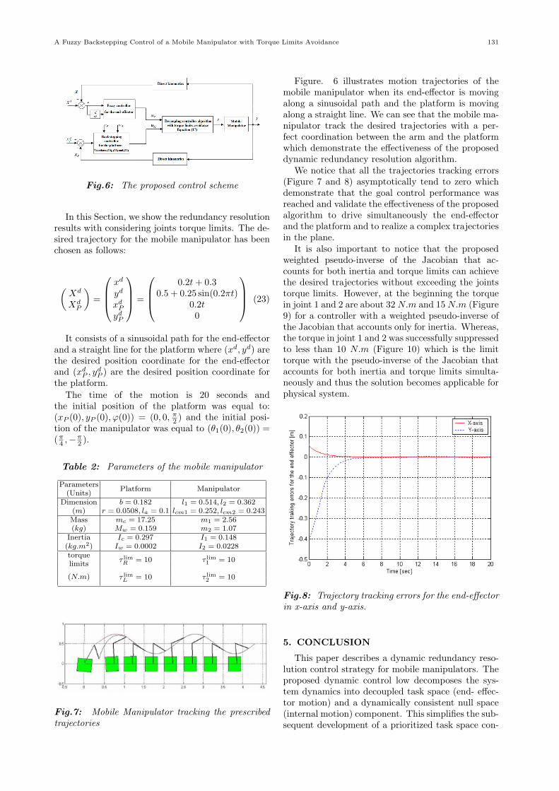
Fig.7: Mobile Manipulator tracking the prescribedtrajectories
Figure. 6 illustrates motion trajectories of themobile manipulator when its end-effector is movingalong a sinusoidal path and the platform is movingalong a straight line. We can see that the mobile ma-nipulator track the desired trajectories with a per-fect coordination between the arm and the platformwhich demonstrate the effectiveness of the proposeddynamic redundancy resolution algorithm.
We notice that all the trajectories tracking errors(Figure 7 and 8) asymptotically tend to zero whichdemonstrate that the goal control performance wasreached and validate the effectiveness of the proposedalgorithm to drive simultaneously the end-effectorand the platform and to realize a complex trajectoriesin the plane.
It is also important to notice that the proposedweighted pseudo-inverse of the Jacobian that ac-counts for both inertia and torque limits can achievethe desired trajectories without exceeding the jointstorque limits. However, at the beginning the torquein joint 1 and 2 are about 32N.m and 15N.m (Figure9) for a controller with a weighted pseudo-inverse ofthe Jacobian that accounts only for inertia. Whereas,the torque in joint 1 and 2 was successfully suppressedto less than 10 N.m (Figure 10) which is the limittorque with the pseudo-inverse of the Jacobian thataccounts for both inertia and torque limits simulta-neously and thus the solution becomes applicable forphysical system.
Fig.8: Trajectory tracking errors for the end-effectorin x-axis and y-axis.
5. CONCLUSION
This paper describes a dynamic redundancy reso-lution control strategy for mobile manipulators. Theproposed dynamic control low decomposes the sys-tem dynamics into decoupled task space (end- effec-tor motion) and a dynamically consistent null space(internal motion) component. This simplifies the sub-sequent development of a prioritized task space con-

132 ECTI TRANSACTIONS ON COMPUTER AND INFORMATION TECHNOLOGY VOL.5, NO.2 NOVEMBER 2011
Fig.9: Trajectory tracking errors for the platform inx-axis and y-axis.
Fig.10: Torque in joint 1 and joint 2 with a pseudo-inverse of the Jacobian that accounts for inertia only
Fig.11: Torque in joint 1 and joint 2 with a pseudo-inverse of the Jacobian that accounts for inertia andtorque limits
trol (of end-effector interactions) and a decoupledbut secondary null space control (of internal motion)in a hierarchical mobile manipulator controller. Anew weighted pseudo-inverse of the Jacobian that ac-counts for both inertia and torque limits is proposedto solve the problems of joints torque limits of thesystem. The proposed controller is capable to accom-plish a good tracking performance without violatingthe joints torque limits of the mobile manipulator.However, further experimentation needs to be carriedout to explore the maximum potentials of the schemewhen other different tasks, parameters or operatingand loading conditions are considered. The practi-cal issues related to the physical mobile manipulatorshould also be investigated.
6. ACKNOWLEDGMENTS
We thank the ministry of higher education and sci-entific research of Tunisia for funding this work.
References
[1] O. Khatib, “Mobile manipulation: The roboticassistant. Robot,” Auton.Syst, vol. 26, no. 2/3,pp. 175-183, 1999.
[2] Y. Das. K Russell. N. Kircanski and A. Golden-berg., “An articulated robotic scanner for minedetection-a novel approach to vehicle mountedsystems,” Proceedings of the SPIE Conference,Orlando. Florida, pp. 5-9, April 1999.
[3] Mars Exploration Rover Launches. NASA PressKit , pp.38-43, June 2003.
[4] H. Seraji, “A Unified Approach to Motion Con-trol of Mobile Manipulators,” The InternationalJournal of Robotics Research, Vol.,17, no.2,Feb.,1998, pp. 107-118.
[5] Y. Yamamoto and X. Yun, “Coordinating loco-motion and manipulation of a mobile manipula-tor,” IEEE Transactions on Automatic Control,39(6), 1326-1332, 1994.
[6] Y. Yamamoto and X. Yun, “Effect of the dy-namic interaction on coordinated control ofmobile manipulators,” IEEE Transactions onRobotics and Automation, 12(5), 816-824, 1996.
[7] O.Khatib, “A unified approach to motion andforce control of robot manipulators: The op-erational space formulation,” IEEE Journal onRobotics and Automation, Vol. RA-3, no, pp. 43-53, 1987.
[8] O.Khatib. K. Yokoi. K. Chang, D. Ruspini. R.Holmberg, and A.Casal, “Vehicle/arm coordina-tion and multiple mobile manipulator decentral-ized cooperation,” in Proc. 1996 IEEE/RSJ In-ternational Conference on Intelligent Robots andSystems, Osaka, Japan, 1996.
[9] J.Tan, N. Xi and Y. wang, “Integrated task plan-ning and control for mobile manipulators,” TheInternational Journal of Robotics Research, vol.22, no.5, pp.337-354, 2003.

A Fuzzy Backstepping Control of a Mobile Manipulator with Torque Limits Avoidance 133
[10] Rajankumar M. Bhatt, Towards Modular Coop-eration Between Multiple Nonholonomic MobileManipulators, Ph.D.dissertation, Univ. of NewYork at Buffalo, USA 2007.
[11] P. Chiacchio, “A new dynamic manipulabilityellipsoid for redundant manipulators,” Robotica,vol. 18, no. 4, pp. 381-387, 2000.
[12] M. Nil. U. Yuzgek and M. Sonmez, “Fuzzy Neu-ral Network Based Intelligent Controller for 3DOF Manipulators,” Proceedings of 5th Interna-tional Symposium on Intelligent ManufacturingSystems, May 29-31, 2006.
[13] R. Fierro and F. Lewis, “Control of a Nonholo-nomic Mobile Robot: Backstepping Kinemat-ics into Dynamics,” Journal of Robotic Systems,14(3), 149-163, 1997.
Mohamed Boukattaya received hisdiploma in Electro-mechanical Engi-neering from the National School of En-gineers of Sfax, Tunisia, in 2002. Fromthe same school, he received the M. S.degree in Automatic and Industrial In-formatics and the Ph. D. degree in Elec-trical Engineering, in 2006 and 2011 re-spectively. He is currently an assistantprofessor at the Preparatory Institute ofEngineers of Sfax. His research interests
include robot modelling and control, especially mobile manip-ulators, mobile platforms, and redundant systems.
Tarak Damak received his diploma inElectrical Engineering from the NationalSchool of Engineers of Sfax, Tunisia, in1989 and the D.E.A degree in Auto-matic Control from the Institut Nationaldes Sciences Appliquees de Toulouse,France, in 1990. He received the Ph.D.degree from the University Paul Sabatierde Toulouse, France, in 1994. In 2006.He then obtained the Universite Habili-tation from National School of Engineers
of Sfax. He is currently a professor in the Department of Me-chanical Engineering of the National School of Engineers ofSfax, Tunisia. His current research interests are in the fields ofdistributed parameter systems, sliding mode control and ob-servers, adaptive nonlinear control.
Mohamed Jallouli received the D.E.Adegree from University of Valenciennes,France, in 1986 in Automatics andthe Ph.D. from University Paris XII,France, in 1991, in Robotics Engineer-ing. He is currently a professor ofElectric and Computer Engineering atNational School of Engineers of Sfax.His current interests include the imple-mentation of intelligent methods (neuralnetwork, fuzzy logic, genetic algorithm)
in robotic and vision system as well as in multisensory datafusion mobile bases.