A FULLY INTEGRATED MOS-C CURRENT-MODE IF FILTER FOR BLUETOOTH by Hussain Alzaher Electrical...
19
A FULLY INTEGRATED MOS-C CURRENT-MODE IF FILTER FOR BLUETOOTH by Hussain Alzaher Electrical Engineering Department King Fahd University of Petroleum & Minerals Dhahran Saudi Arabia
-
date post
20-Dec-2015 -
Category
Documents
-
view
214 -
download
0
Transcript of A FULLY INTEGRATED MOS-C CURRENT-MODE IF FILTER FOR BLUETOOTH by Hussain Alzaher Electrical...
A FULLY INTEGRATED MOS-C CURRENT-MODE IF FILTER FOR
BLUETOOTH
by
Hussain Alzaher
Electrical Engineering DepartmentKing Fahd University of Petroleum & Minerals
Dhahran Saudi Arabia
Outline Introduction
• Bluetooth technology• Receiver Architecture
Requirements of IF Filter Proposed Technique
• Unity gain cells• Non-Linearity Cancellation• Fully Differential Architecture
Proposed Low IF Bandpass Filter• Filter design topology• Filter characteristics
Simulation Result• ac response• Filter specifications
Conclusions
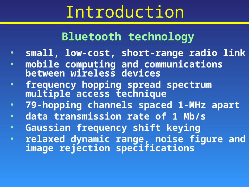
IntroductionBluetooth technology
• small, low-cost, short-range radio link• mobile computing and communications
between wireless devices• frequency hopping spread spectrum multiple
access technique• 79-hopping channels spaced 1-MHz apart• data transmission rate of 1 Mb/s• Gaussian frequency shift keying• relaxed dynamic range, noise figure and image
rejection specifications
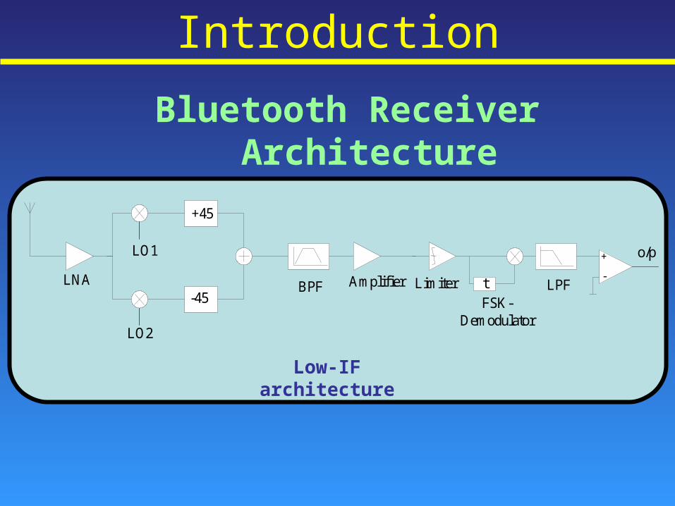
Introduction
Bluetooth Receiver Architecture
LNA
LO1
LO2
BPF-45
+45
Amplifier tLimiterFSK-
Demodulator
LPF
o/p+
-
Low-IF architecture
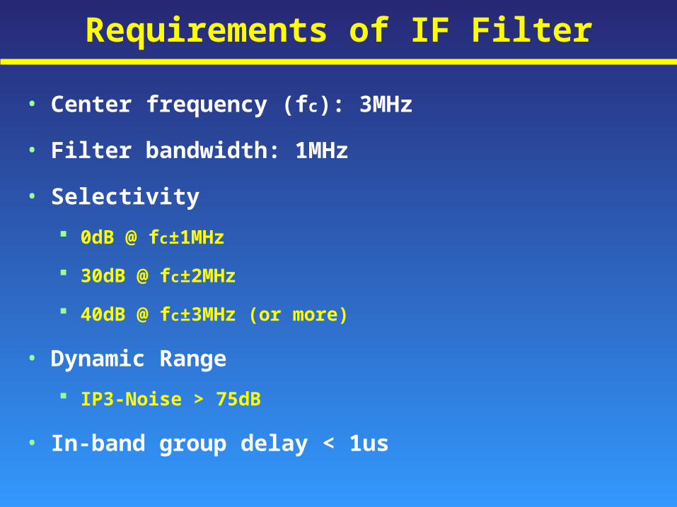
• Center frequency (fc): 3MHz
• Filter bandwidth: 1MHz
• Selectivity
0dB @ fc±1MHz
30dB @ fc±2MHz
40dB @ fc±3MHz (or more)
• Dynamic Range
IP3-Noise > 75dB
• In-band group delay < 1us
Requirements of IF Filter
Proposed Technique
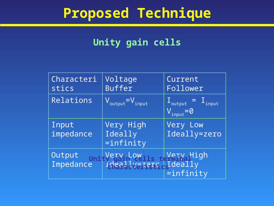
Unity gain cells
Characteristics Voltage Buffer Current Follower
Relations Voutput=Vinput Ioutput = Iinput
Vinput=0
Input impedance
Very HighIdeally =infinity
Very LowIdeally=zero
Output Impedance
Very LowIdeally=zero
Very HighIdeally =infinity
Unity gain cells terminal characteristics
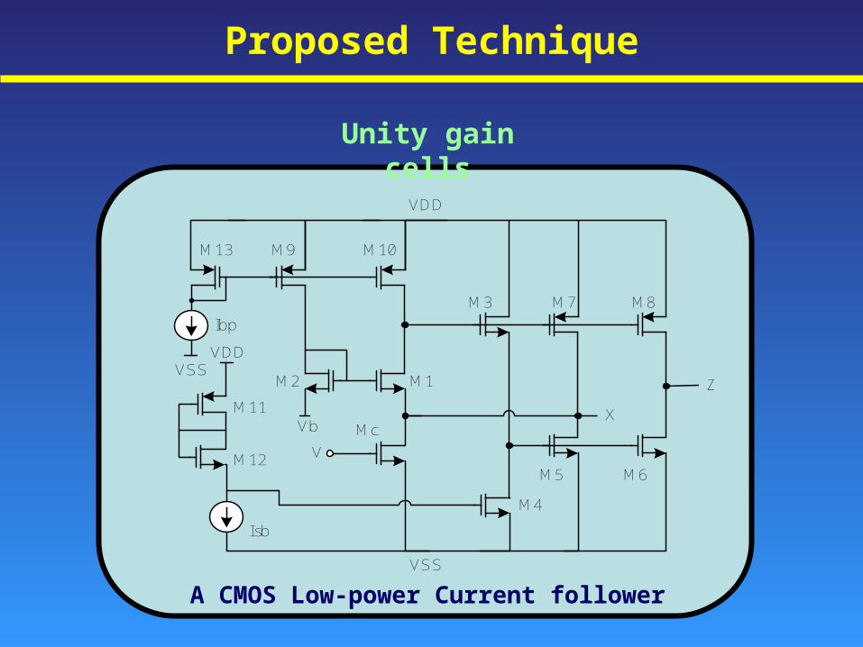
A CMOS Low-power Current follower
M13 M9 M10
M2 M1
M3 M7 M8
M6M5
M4
McXM11
M12
VDD
Vb
V
Z
Isb
Ibp
VDD
VSS
VSS
Proposed Technique
Unity gain cells
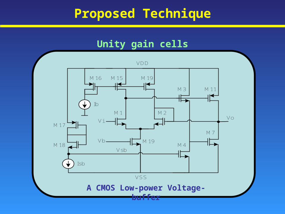
Proposed Technique
Unity gain cells
A CMOS Low-power Voltage-buffer
M16
Vi
Vb
Vsb
M15 M19
M3 M11
M2M1
M7
M4M19
M17
M18
Ib
Isb
VDD
VSS
Vo
Proposed Technique
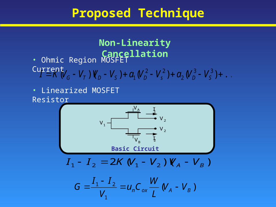
Non-Linearity Cancellation
VA
V2
V2V1
VB
I1
I2
))((2 2121 BA VVVVKII
...)()())(( 332
221 SDsDSDTG VVaVVaVVVVKI
)(1
21BAoxn VV
L
WCu
V
IIG
• Ohmic Region MOSFET Current
• Linearized MOSFET Resistor
Basic Circuit
Proposed Technique
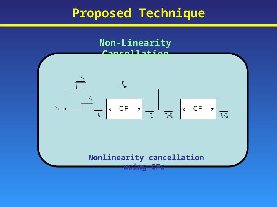
Non-Linearity Cancellation
Nonlinearity cancellation using CFs
CF x z CF x z
V B
V A I 1
I 2 I 1 -I 2 I 2 I 1 -I 2 V 1
Proposed Technique
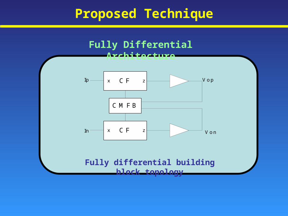
Fully Differential Architecture
Fully differential building block topology
C Fx z
C Fx z
C M F B
Ip
In
V o p
V o n
Proposed Technique
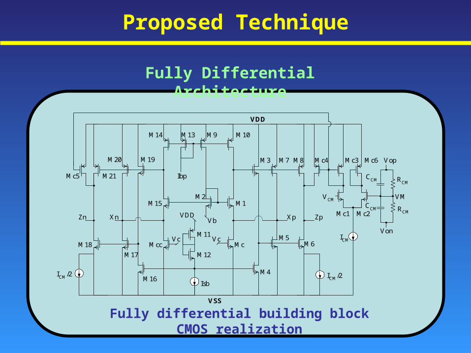
Fully Differential Architecture
M18
M17
M16
M12
M11
MccVc
VDDVb
Vc
M15M2
M1
Mc
M4
M5M6
IsbICM/2ICM/2
ICM
VCM
Mc1 Mc2
Mc6Mc3Mc4M3 M7 M8
M10M9M13M14
M19M20
M21Mc5
Zn Xn Xp Zp
CCM RCM
CCM RCM
VM
VDD
VSS
Ibp
Vop
Von
Fully differential building block CMOS realization
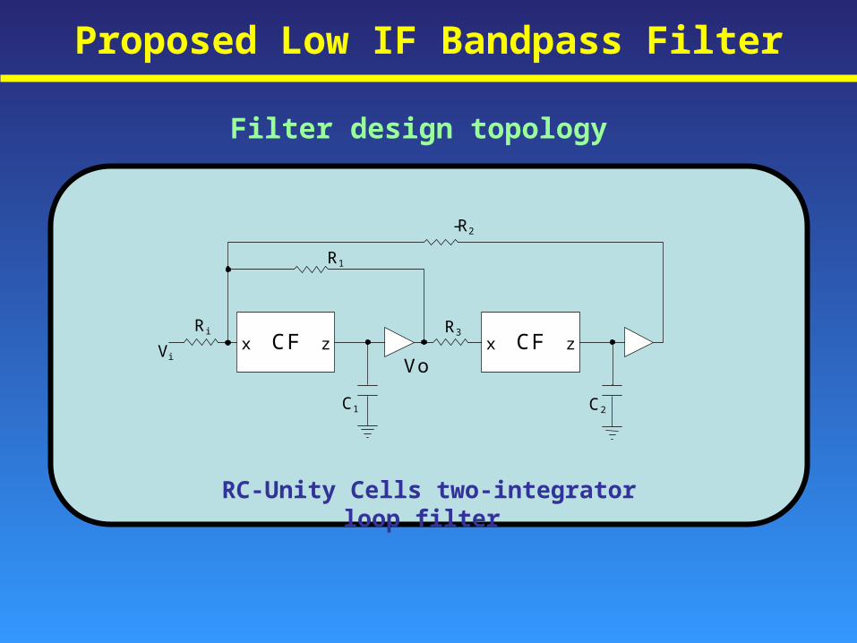
Proposed Low IF Bandpass Filter
-R 2
CF x z CF x z R i
R 1
R 3
C 1 C 2
V i
Vo
RC-Unity Cells two-integrator loop filter
Filter design topology
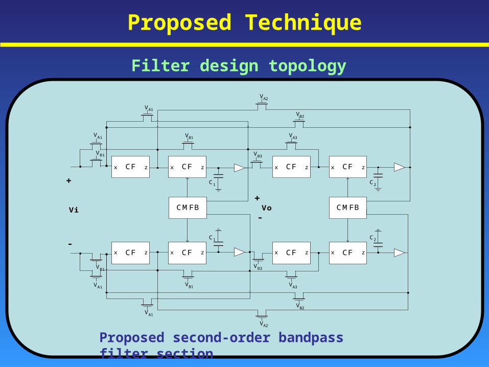
Proposed Technique
Filter design topology
CMFBCMFB
CFx z CFx z CFx z CFx z
C1 C2
VBi
VAi VB1
VB3
VB2
VA3
VA2
VA1
CFx z CFx z CFx z CFx z
C1 C2
VBi
VAiVB1
VB3
VB2
VA3
VA2
VA1
Vi
+
-
Vo+
-
Proposed second-order bandpass filter section
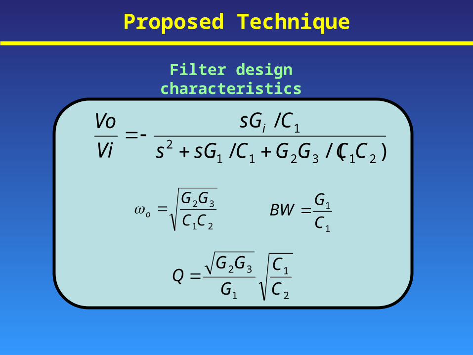
Proposed Technique
Filter design characteristics
)/(/
/
2132112
1
CCGGCsGs
CsG
Vi
Vo i
21
32
CC
GGo
1
1
C
GBW
2
1
1
32
C
C
G
GGQ
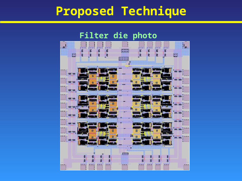
Proposed Technique
Filter die photo
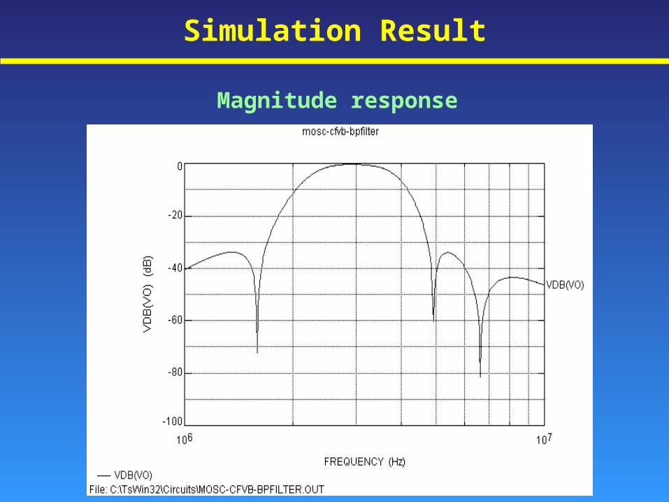
Simulation Result
Magnitude response
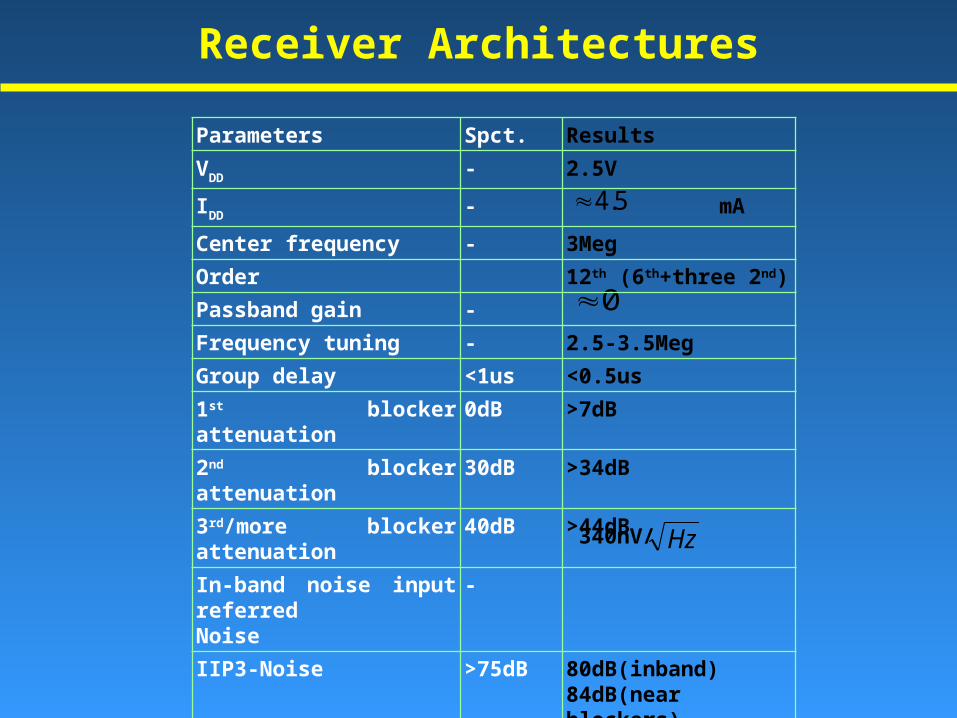
Receiver Architectures
5.4
0
340nV/ Hz
Parameters Spct. Results
VDD - 2.5V
IDD - mA
Center frequency - 3Meg
Order 12th (6th+three 2nd)
Passband gain -
Frequency tuning - 2.5-3.5Meg
Group delay <1us <0.5us
1st blocker attenuation 0dB >7dB
2nd blocker attenuation 30dB >34dB
3rd/more blocker attenuation 40dB >44dB
In-band noise input referred Noise
-
IIP3-Noise >75dB 80dB(inband)84dB(near blockers)91dB(distant blockers)
Area 1.7 mm x 1.7 mm
Conclusions
• CMOS bandpass filter for fully integrated Bluetooth receiver
• Using unity gain cells
• Utilizing linearized MOSFET resistors for tuning
• 12th order = 3 X 2nd order bandpass + 3 X 2nd order notches
• Dynamic range = 53dB for in-band signals
• Selectivity improved by cascading
• Current consumption can be optimized