A Framework for the Coordination of Legged Robot Gaits · A Framework for the Coordination of...
8
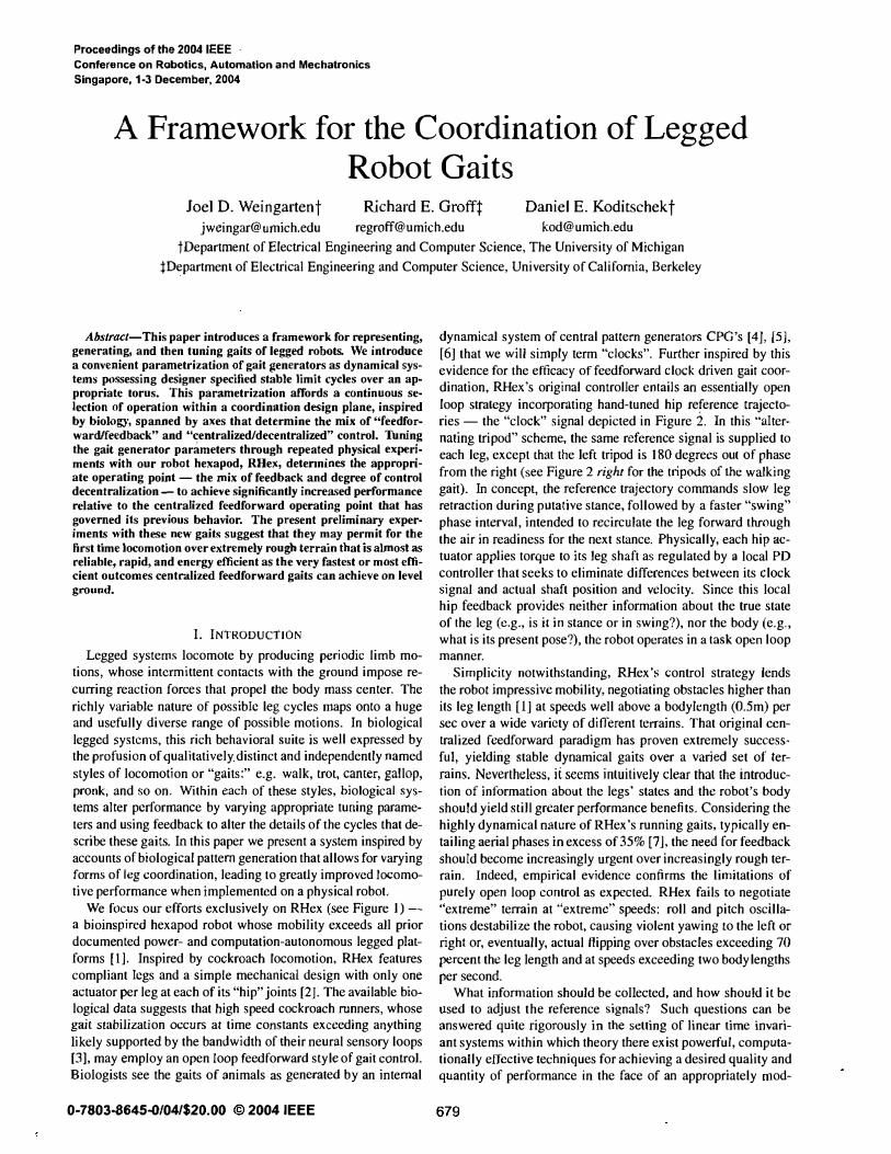
Proceedings of the 2DD4 IEEE . Conference on Robotics, Automation and Mechatronics Singapore, 1·3 December, 2004 A Framework for the Coordination of Legged Robot Gaits Joel D. Weingartent chard E. Grofft Daniel E. Koditschekt jweingar@umich.edu regroff@umich.edu [email protected]du tDepartmenl of Electrical Engineering and Computer Science, The University of Michigan Department of Electrical Engineering and Computer Science, University of Califoia, Berkeley Ahslract-This paper introduces a framework for representing, generating, and then tuning gaits of legged robots. We introduce a convenient parametrization of gait generators as dynamical sys- tems possessing designer specified stable limit cyes over an ap· propriate torus. This parametrization affords a continuous se· lection of operation within a coordination dign plane, inspired by biolo, spanned by axes that determine e mix of ''reed for- warfeedback" and "centralized/decentralized" control. Tuning the gait generator parameters through repeated physical exפri· ments with our robot hexapod, RHe", detennin the appropri· ate operating point - the mix of feedback and degree of control decentralization -to achieve significantly increed performance relative to the centralized feedforward operating point that has goveed its previous bebavior. The present preliminary exper· imenʦ with the new gail� suggt that they may permit for the first time locomotion over extremely rou terrain that is almost reliable, rapid, and energy efficient as tbe very fastest or most effi- cient outcomes centdlized feedforward gaits can achieve on level ground. 1. INTRODUCTION Legged systems locomote by producing periodic limb mo- tions, whose intermittent contacts with the ground impose re- cuing reaction forces that propel the body mass center. The richly variable nature of possible leg cycles maps onto a huge and usefully diverse range of possible motions. In biological legged systems, this rich behavioral suite is well expressed by the profusion of qualitatively distinct and independently named styles of locomotion or "gaits:" e.g. walk, trot, canter, gallop, pronk, and so on. Within each of these styles, biological sys- tems alter performance by varying appropriate tuning parame- ters and using feedback to alter the details of the cycles that de- scribe these gaits. In this paper we present a system inspired by accounts of biological patte generation that allows for varying forms of leg coordination, leading to greatly improved lomo- tive performance when implemented on a physical robot We focus our efforts exclusively on RHex (see Figure I) - a bioinspired hexapod robot whose mobility exceeds all prior documented power- and computation-autonomous legged plat- forms [1]. Inspired by cockroach locomotion, RHex features compliant legs and a simple mechanical design with only one actuator per leg at each of its "hip" joints [2]. The available bio- logical data suggests that high speed cockroach nners, whose gait stabilization occurs at time constants exceeding anything likely supported by the bandwidth of their neural sensory loops [3], may employ an open loop feedforward style of gait control. Biologists see the gaits of animals as generated by an inteal 0-7803(645/04/$20.00 © 2004 IEEE dynamical system of central patte generators CPG's [4J, [5J, [6] that we will simply term "clocks". Further inspired by this evidence for the efficacy offeedforward clock driven gait COOf- dination, RHex's original controller entails an essentially open loop strategy incorporating hand-tuned hip reference trajecto- ries - the "clock" signal depicted in Figure 2. In this "alter- nating tripod" scheme, the same reference signal is supplied to each leg, except that the left tripod is 180 degrees ou( of phase from the right (see Figure 2 right for the tpods of the walking gait). In concept, the reference trajectory commands slow leg retraction during putative stance, followed by a faster "swing" phase interval, intended to recirculate the leg forward tough the air in readiness for the next stance. Physically, each hip ac- tuator applies torque to its leg shaft as regulated by a local PD controller that seeks to eliminate differences between its clock signal and actual shaft position and velocity. Since this local hip feedback provides neither information about the true state of the leg (e.g., is it in stance or in swing?), nor the body (e.g., what is its present pose?), the robot operates in a task open loop manner. Simplicity notwithstanding, RHex's control strategy lends the robot impressive mobility, negotiating obstacles higher than its leg length [IJ at speeds well above a bodylength (O.5m) per sec over a wide variety of different terrains. That original cen- tralized feedforward paradigm has proven extremely success- ful, yielding stable dynamical gaits over a varied set of ter- rains. Nevertheless, it seems intuitively clear that the introduc- tion of information about the legs' states and the robot's body should yield still greater performance benefits. Considering the highly dynamical nature of RHex's running gaits, typically en- tailing aerial phases in excess of 35% [7], the need for feedback should become increasingly urgent over increasingly rough ter- rain. Indeed, empirical evidence confirms the limitations of purely open loop control as exפcted. RHex fails to negotiate "extreme" teain at "extreme" speeds: roll and pitch oscilla- tions destabilize the robot, causing violent yawing to the left or right Of, eventually, actual Hipping over obstacles exceeding 70 פrcent the leg length and at speeds exceeding two body lengths per second. What inf oation should be collected, and how should it be used to adjust the reference signals? Such questions can be answered quite rigorously in the setting of linear time invari- ant systems within which theory there exist powerful, computa- tionally effective techniques for achieving a desired quality and quantity of performance in the face of an appropriately mod- 679
-
Upload
phungkhuong -
Category
Documents
-
view
222 -
download
1
Transcript of A Framework for the Coordination of Legged Robot Gaits · A Framework for the Coordination of...
Proceedings of the 2DD4 IEEE . Conference on Robotics, Automation and Mechatronics
Singapore, 1·3 December, 2004
A Framework for the Coordination of Legged Robot Gaits
Joel D. Weingartent Richard E. Grofft Daniel E. Koditschekt
[email protected] [email protected] [email protected]
tDepartmenl of Electrical Engineering and Computer Science, The University of Michigan
:j:Department of Electrical Engineering and Computer Science, University of California, Berkeley
Ahslract-This paper introduces a framework for representing, generating, and then tuning gaits of legged robots. We introduce a convenient parametrization of gait generators as dynamical systems possessing designer specified stable limit cycles over an ap· propriate torus. This parametrization affords a continuous se· lection of operation within a coordination design plane, inspired by biology, spanned by axes that determine the mix of ''reed forward/feedback" and "centralized/decentralized" control. Tuning the gait generator parameters through repeated physical experi· ments with our robot hexapod, RHe", detennines the appropri· ate operating point - the mix of feedback and degree of control decentralization - to achieve significantly increased performance relative to the centralized feedforward operating point that has governed its previous bebavior. The present preliminary exper· iments with these new gail� suggest that they may permit for the first time locomotion over extremely rough terrain that is almost as reliable, rapid, and energy efficient as tbe very fastest or most efficient outcomes centl'"dlized feedforward gaits can achieve on level ground.
1. INTRODUCTION Legged systems locomote by producing periodic limb mo
tions, whose intermittent contacts with the ground impose recurring reaction forces that propel the body mass center. The richly variable nature of possible leg cycles maps onto a huge and usefully diverse range of possible motions. In biological legged systems, this rich behavioral suite is well expressed by the profusion of qualitatively distinct and independently named styles of locomotion or "gaits:" e.g. walk, trot, canter, gallop, pronk, and so on. Within each of these styles, biological systems alter performance by varying appropriate tuning parameters and using feedback to alter the details of the cycles that describe these gaits. In this paper we present a system inspired by accounts of biological pattern generation that allows for varying forms of leg coordination, leading to greatly improved locomotive performance when implemented on a physical robot
We focus our efforts exclusively on RHex (see Figure I) -
a bioinspired hexapod robot whose mobility exceeds all prior documented power- and computation-autonomous legged platforms [1]. Inspired by cockroach locomotion, RHex features compliant legs and a simple mechanical design with only one actuator per leg at each of its "hip" joints [2]. The available biological data suggests that high speed cockroach runners, whose gait stabilization occurs at time constants exceeding anything likely supported by the bandwidth of their neural sensory loops [3], may employ an open loop feed forward style of gait control. Biologists see the gaits of animals as generated by an internal
0-7803008645-0/04/$20.00 © 2004 IEEE
dynamical system of central pattern generators CPG's [4J, [5J, [6] that we will simply term "clocks". Further inspired by this evidence for the efficacy offeedforward clock driven gait COOfdination, RHex's original controller entails an essentially open
loop strategy incorporating hand-tuned hip reference trajectories - the "clock" signal depicted in Figure 2. In this "alternating tripod" scheme, the same reference signal is supplied to each leg, except that the left tripod is 180 degrees ou( of phase from the right (see Figure 2 right for the tripods of the walking gait). In concept, the reference trajectory commands slow leg retraction during putative stance, followed by a faster "swing" phase interval, intended to recirculate the leg forward through the air in readiness for the next stance. Physically, each hip actuator applies torque to its leg shaft as regulated by a local PD controller that seeks to eliminate differences between its clock signal and actual shaft position and velocity. Since this local hip feedback provides neither information about the true state of the leg (e.g., is it in stance or in swing?), nor the body (e.g., what is its present pose?), the robot operates in a task open loop manner.
Simplicity notwithstanding, RHex's control strategy lends the robot impressive mobility, negotiating obstacles higher than its leg length [IJ at speeds well above a bodylength (O.5m) per sec over a wide variety of different terrains. That original centralized feedforward paradigm has proven extremely successful, yielding stable dynamical gaits over a varied set of terrains. Nevertheless, it seems intuitively clear that the introduction of information about the legs' states and the robot's body should yield still greater performance benefits. Considering the highly dynamical nature of RHex's running gaits, typically entailing aerial phases in excess of 35% [7], the need for feedback should become increasingly urgent over increasingly rough terrain. Indeed, empirical evidence confirms the limitations of purely open loop control as expected. RHex fails to negotiate "extreme" terrain at "extreme" speeds: roll and pitch oscillations destabilize the robot, causing violent yawing to the left or right Of, eventually, actual Hipping over obstacles exceeding 70 percent the leg length and at speeds exceeding two body lengths per second.
What information should be collected, and how should it be used to adjust the reference signals? Such questions can be answered quite rigorously in the setting of linear time invariant systems within which theory there exist powerful, computationally effective techniques for achieving a desired quality and quantity of performance in the face of an appropriately mod-
679
eled range of perturbations. However everything about RHex is nonlinear - its kinematics [I] and dynamics [8], actuator constraints, and sensor suite [9] - and no presently available theoretically sound methodogy exists for rational control design in this setting. Inspired by biology, we tum instead to a developing body of intuition and practice emerging from a decade's work with dynamically dexterous machines [10],[11),[12] that has recently begun to yield formal design prescriptions as well [13]. Inspired by the engineer's desire for simple robust design, we introduce in this initial exploration the most minimal extension to RHex's original sensory suite we can imagine, addressing the question of how to couple simple features of the mechanical state space back into a robot's internal state space before moving ahead with more sophsticated sources of feedback and their concomitantly more complicated interactions.
At a sufficiently high level, such questions can be addressed rationally by considering first the issue of design and then the matter of operating point. Since the limbs' dynamical coupling is already specified by the mechanical platform and the ambient terrain, the remaining design decisions concern how their internal clocks (i.e. reference trajectory generators) should be coupled to each other and to the limbs. The nature of the internal coupling is constrained only by a robot's computational resources. How these clocks are influenced by and affect the limbs and body is much more bound up in the details of the available sensory suite and actuator electronics. In this research, we have chosen for our internal architecture the framework of coupled phase regulation introduced by Klavins
[14 J,[ 13] with a new clock deformation scheme generalizing the original RHex two phase (slower-faster) arrangement. This internal clock system will be introduced in Section II-D. The major remaining design choice - the coupling between the clock system and the motor system - will be detailed in Section II-C.
The nature of the mechanism, the clocks, and their mutual couplings once determined, operating point selection now occurs within a coordination space characterized by at least two distinct architectural "axes:" the relative strength of the feedback and feedforward components; and the relative influence of the clocks on each other. In this view, choice of operating point reflects a decision of how centrally to bring to bear the information originating at more distal body locations. Even a brief perusal of the biological literature on locomotion coordination schemes offers copious evidence [15], [1 6], [4], [5], [17J, [18], [6], that different animals confronting differing environments operate in different regions of this design space. Closer to hand, intuition based upon empirical experience with RHex gives clues as to what style of coordination may be appropriate for what sort of environment. Both our physical experience and biology inspires our search for a parameterized gait generation system that permits exploration of the feedforward-feedback and centralized-decentralized axes of the controls space. A discussion of how to select the operating point in this architectural design space as a function of environmental conditions is presented in Section III.
Successfully exploiting the potential benefits of the architectural axes is clearly predicated on successfully using sensors to inform feedback. Recently, biologists have begun to study how minimal sensor information is adequate for producing impres-
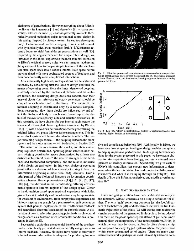
Fig. I. RHex is a power- and computation-autonomous robotic hexapod, fealUring compliant legs and a simple mechanical design. The chassis measures 48cmx 22cmx 12.5cm. and the distance from hip to ground in normal standing posture is \5.5cm.
211" ,-., '" c
0 A .:::2 3 "g2"
t ... ......., <1)
"OiJ1I" A 0 c <t: � 1 j'2 0 A
0.2 0.4 0.6 0.8 1 Time (sec.)
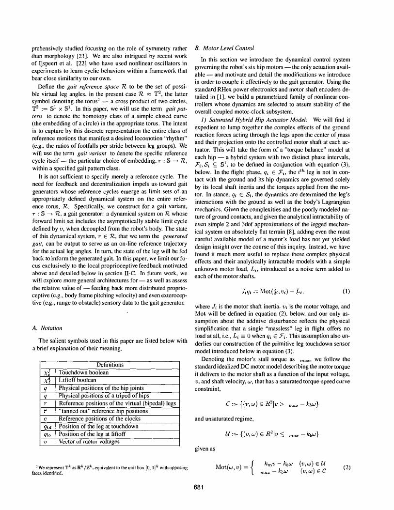
Fig.2. Left - The "clock'· signal that drives the legs for centralized-feed forward walking. Right - Tripods of the walking gait.
sive and complicated behaviors [19]. Additionally, in RHex, we have seen how simple yet intelligent design enables our system to display impressive performance. In designing feedback options for the system presented in this paper we have again chosen to take inspiration from biology, and use a minimal complement of sensory information. Specifically we give each of
RHex's hip controllers just enough new information to determine when the leg it is driving has made contact with the ground ("stance") and when it is swinging through air ("flight"). The details of how this information derived and used is given in section II-C
II. GAIT GENERATION SYSTEM
Gaits and gait generation have been addressed variously in the literature, without consensus on a single definition for either. The term "gait" sometimes connotes just the footfall pattern of the behavior [20], and other times includes the full kinematic trajectories of the joints. We will use the term to describe certain properties of the generated limit cycle to be introduced. Our focus on the phase space representation of gait seems most natural given the morphology of our robotic platform, RHex, in which the legs may be rotated arbitrarily often about the hip, as compared to many legged systems where the joints move within some constrained seE of angles. There are many alternative frameworks, perhaps the most interesting and most com-
680
prehensively studied focusing on the role of symmetry rather than morphology [21]. We are also intrigued by recent work of Ijspeert et al. [22] who have used nonlinear oscillators in experiments to learn cyclic behaviors within a framework thar bear close similarity to our own.
Define the gait reference space n to be the set of possible virtual leg angles, in the present case R ;::,; ]'2, the latter symbol denoting the torusl - a cross product of two circles, ]'2 := §l x §l. In this paper, we will use the term gait pattern to denote the homotopy class of a simple closed curve (the embedding of a circle) in the appropriate torus. The intent is to capture by this discrete representation the entire class of reference motions that manifest a desired locomotion "rhythm" (e.g., the ratios of footfalls per stride between leg groups). We will use the term gait variant to denote the specific reference cycle itself - the particular choice of embedding, r : § --t n, within a specified gait pattern class.
It is not sufficient to specify merely a reference cycle. The need for feedback and decentralization impels us toward gait generators whose reference cycles emerge as limit sets of an appropriately defined dynamical system on the entire reference torus, R. Specifically, we construct for a gait variant, r : § --t n, a gait generator: a dynamical system on n whose forward limit set includes the asymptotically stable limit cycle defined by v, When decoupled from the robot's body. The state of this dynamical system, r E R, that we term the generated gait, can be output to serve as an on-line reference trajectory for the actual leg angles. In tum, the state of the leg will be fcd back to inform the generated gait. In this paper, we limit our focus exclusively to the local proprioceptive feedback motivated above and detailed below in section II-C. In future work, we will explore more general architectures for - as well as assess the relative value of - feeding back more distributed proprioceptive (e.g., body frame pitching velocity) and even exteroceptive (e.g., range to obstacle) sensory data to the gait generator.
A. Notation
The salient symbols used in this paper are listed below with a brief explanation of their meaning.
Definitions
x1 Touchdown boolean X} LiftoH boolean
q Physical positions of the hip jOints
q Physical positions of a tripod of hips r Reference positions of the virtual (bipedal) legs f "fanned out" reference hip positions c Reference positions of the clocks qtd Position of the leg at touchdown qlo Position of the leg at liftoff v Vector of motor voltages
I We represent 1fk as]Rk jZk, equivalent to the unit box [0, 11 k with opposing faces identified.
B. Motor Level Control
In this section we introduce the dynamical control system governing the robot's six hip motors - the only actuation available - and motivate and detail the modifications we introduce in order to couple it effectively to the gait generator. Using the standard RHex power electronics and motor shaft encoders detailed in [1], we build a parametrized family of nonlinear controllers whose dynamics are selected to assure stability of the overall coupled motor-clock subsystem.
1) Saturated Hybrid Hip Actuator Model: We will find it expedient to lump together the complex effects of the ground reaction forces acting through the legs upon the center of .mass and their projection onto the controlled motor shaft at each actuator. This will take the form of a "torque balance" model at each hip - a hybrid system with two distinct phase intervals, F;, Sj S; §l, to be defined in conjunction with equation (3), below. In the flight phase, qj E :Fi, the ith leg is not in contact with the ground and its hip dynamics are governed solely by its local shaft inertia and the torques applied from the motor. In stance, qi E Si, the dynamics are determined the leg's interactions with the ground as well as the body's Lagrangian mechanics. Given the complexities and the poorly modeled nature of ground contacts, and given the analytical intractability of even simple 2 and 3dof approximations of the legged mechanical system on absolutely flat terrain (8], adding even the most careful available model of a motor's load has not yet yielded design insight over the course of this inquiry. Instead, we have found it much more useful to replace these complex physical effects and their analytically intractable models with a simple unknown motor load, Li, introduced as a noise term added to each of the motor shafts.
(1 )
where Ji is the motor shaft inertia, Vi is the motor voltage, and Mot will be defined in equation (2), below, and<our only assumption about the additive disturbance reflects the physical simplification that a single "massless'.' leg in flight offers no load at all, i.e., Li == a when qi E :Fj• This assumption also underlies our construction of the primitive leg touchdown sensor model introduced below in equation (3).
Denoting the motor's stall torque as max, we follow the standard idealized DC motor model describing the motor torque it delivers to the motor shaft as a function of the input voltage, v, and shaft velocity, w, that has a saturated torque-speed curve constraint,
and unsaturated regime,
given as
Mot(w,v) = { 681
(v,w) E U (v,w) E C (2)
C. Sensory Feedback to Motor Controller
RHex, is equipped with a slowly growing suite of increasingly well characterized and and integrated sensors including a primitive I1v1U (a bank of rate gyros and accelerometers), a leg strain based pose sensor [23], [9], and a 640 x 480 pixel standard frame rate CCD camera [24]. There are many promising
and even intuitively compelling ways to imagine introducing these new sensory modalities into the motor control loop. But the physical and conceptual cost of perception so well articulated in the prior robotics literature [25] impels us to squeeze the greatest virtue we can from existing sensors before rushing to more extravagant schemes. In the specific context of RHex these new sensors threaten to reintroduce fragility to a mechanical platform assiduously refined for robustness. For example, our experimental leg strain sensory system [23] was not sufficiently robust at the time of writing to endure the harsh environmental conditions arising from the experimental paradigm to be described in Section IV, below. Hence, we resort in this paper to a surrogate measurement of foot touchdown , More generally, it seems incumbent upon experimentalists in robotics to establish a baseline of performance associated with careful use of simple sensor suites against which the incremental benefit of any specific new sensor can be compared. Thus, in the present paper, we restrict ourselves to the original RHex 1.0 hip shaft
. sensors [lJ, but we will use them in a more refined manner than previously, as this section details.
Even with this minimal sensing we are able successfully to achieve our feedback goals. As anticipated from above, three ideas based upon a great deal of empirical observation guide our approach to feedback control. First, one would like the legs to be synchronized within a tripod. Second, touchdown should occur simultaneously within a tr ipod. Third the legs should reduce their power output at the moment of touchdown.
The motivation for these three objectives seems most easily conveyed by considering the typical response of the prior task open loop controller in the face of an early physical leg transition from flight to stance resulting from its encountering a raised "obstacle" on the presumably flat terrain. Since touchdown has (unknown to the controller) occurred during the fast phase of the reference signal's cycle, the rapidly increasing PD errors inject energy into the system thereby pushing on the obstacle. In the most common instance where one side of the robot touches down before the other (most often due to an obstacle, inducing a high and low side of the robot) the early pushing is exactly the opposite of what is desired to keep the robot stable, as pushing on the high side causes additional rolling. Since RHex has only one actuated degree of freedom per leg, achieving energy efficient "touchdowns" that slow toe velocities at impact to avoid the leg bouncing off the ground is difficult. Thus, detecting touchdown and reducing the current to the motors at those instances would also be beneficial. These observations
combine to motivate our desire to allow the robot freedom to adjust independently the trajectories of each of its legs depending on its current state.
Next, there is a run time question of how to determine specific interconnection strengths as a function of particular operating conditions. While allowing each leg the freedom to react to its environment is crucial, stable walking/running is tied to
the robots ability to synchronize each tripod and in general have
these tripods be 180 degrees out of phase. In some sense these goals are contradictory, as adjusting each leg will by definition relax the rigid tripod configuration. In this paper we parameterize the control to allow for varying degrees of decentralization (allowing each tripod and then each leg within the tripod to individually react to its environment) while guaranteeing that at steady state steady state within a uniformly flat environment the the tripods are synchronized and in lock-step.
J) The Surrogate Touchdown Sensor and Derived Measurements; The experiments reported below rely upon a surrogate for each leg 's touchdown and liftoff events inferred from the heuristic detection of sudden increases in its hip actuator's tracking error as originally described in [26]. We denote the angle at whieh this sensor reports touchdown for the ith leg by qi,td and the angle at which that leg lifts off the ground by qi,lo' For the kth stance event of a given leg, we find it further expedient to introduce a state-dependent partition of it's configuration space, into a "flight" phase, Fi(k) := (qi,lo(k),qi,td(k)), and its complement in 11'1, "stance", SiC k) := [qi,td(k), qi,lo(k+ 1)]. We will usually suppress the stance index number, k when using these symbols. We can then define the angle beyond which a leg has passed its touchdown position as,
qi,td(k) E Fi(k) qi,td(k) E SiCk) (3)
so that, d!;{q) ;= (d1,!;{qtl, ... , d6,dq6)) effectively integrates the difference between each leg's touchdown angle and its current position during its stance phase, and is then reset to zero after liftoff for each leg. The above computation constitutes the only additional sensory information that this new controller uses relative to the scheme reported in our previous work [1], [2J, [7].
2) Tripod Swing and Touchdown Synchronization: For the experiments reported in this paper, we will be coordinating left,
qL := (qi)iEl'J,O = {1,3,5} and right, qR := (qi)iE£,t: = {2, 4, 6} leg tripods (see figure 2 right), whose generic instance will be denoted by the variable q E 11'3. Similarly, we will denote by ddq), the application of the kth touchdown difference function to each of the tripod's hip angles, assuming that each individual hip within a tripod advances to its next touchdown, qj E Sj(k + 1) only after the other two are in the prior flight or subsequent stance qi E Si(k)U.:Fi(k+ 1) as well, for i i- j E 0 and i =F j E E. Loosely following Klavins [13], we will encode desired tripod phase relationships by recourse to a scalar valued function, p : 11'3 --* lR,
3 jj(q) := L:p(qi); p(u) = 1 - cos(u) (4)
i=1
which vanishes exactly when the three angles are at zero. Composing this with pairwise differences,
-1 o
-1 (5)
yields a function that vanishes exactly when .all three angles of both tripods agree, encoding the synchronization of a tripod's
682
legs. Composing that, in tum, with the the touchdown offset angles,
(6)
yields a function that vanishes exactly when all three hips of each tripod touch down simultaneously and maintain an identical future difference to their touchdown configurations. Taking the sum of these last two compositions,
(7)
roughly encodes both tasks, even though they cannot simultaneousl y be brought to zero on a non-fiat surface with the robot's body nonnal aligned to that of the ground.
In our experience, much energy is wasted during the leg liftoff and touchdown events. Reducing the power to the legs at touchdown has the effect of reducing the amount of energy wasted from their "bouncing" off the ground as well as avoiding doing work against gravity in the retraction phase. At liftoff re
ducing the power reduces energy wasted due to trajectory mismatch with the physical system. By applying the following saturation function. a, at touchdown and cakeoff we can reduce the maximum voltage commanded to the motors from am to aD at the desired times in the leg cycle. Defining a touchdown sensitive saturation function to be
u>l u <-}
luI s: 1 (8)
where X E {O, I} and X = xi V x{ where xi and X{ E {O, I} and
and
X� = { I qi E [qi,td, qi,td + qR,] f 0 qi ¢ !qi,td, qi,td + qR,]
xt = { � qi E [qi,la, q.i,lo + qR21 qi ¢ [qi,la, qi,lo + qR2J
(9)
(10)
where qR!, qR, E §1 represent ranges around touchdown and liftoff respectively we are able to reduce the voltage passed to
each motor at the appropriate times. 3) Closed Loop Hip Tracking Controller: Our hip controller
takes the form of a "nonlinear PD" (Le. a Potential-Dissipative [27]) tracker- that dissipates error potentials using a saturated velocity error term based upon (8) in a manner we now describe. The potential terms whose dissipation encodes the desired behavior arise from summing the tripod synchronization potential
(7) in combination with a gait reference tracking error potential to be defined in (12). The "tracking errors" arise from a comparison of each tripod's physical hip location with the appropriate component of the coordinated clock signals, h, T2]T E R, whose form will be detailed in Subsection n.D. These clock signals are distributed appropriately to the left and right tripods by the "fanned out" embedding of 11'2 into 11'6 given by
f = h T2 TI T2 TI T2f (11)
and yield the obvious tracking error, e := f - q, between the reference and physical hip angles. A saturating tracking error potential,
6 . 2 (e) = L "'f3,ei 2 (I 2)
i=1 1 + J),fh ei
insures that the gradients used in the tracking controller will have a bounded magnitude that can be adjusted by a simple set of gains. Adding together the position and error regulating gradients with a saturating derivative term, the hip controller takes the fonn,
where gains "'syn, "'td, rip!, rip2, "'d and ao vary the relative strength of each component of the motor control equation. Note the above equation for the motor voltage controller assumes the validity of the idealized motor model (2), assumes that the gains and saturation bounds of the constituent terms in (13) guarantee operation in the unsaturated regime, U in (2), and then simply inverts the function Mot
It should be noted that while the components of the feedback function were chosen via the developers' intuition, the form of the ultimate control system - the actuator inputs (13), and reference generator (14) and error integrator (15) schemes to be defined below - have been chosen to guarantee stabi1ity of the system, absent interaction with the environment, i.e., for Li =
0, i = 1 . . . 6. Explicitly, when the saturated damping (first term on the right hand side) of (13) is a�pIied to q alone, the reader may verify that, Ilgl12+lIf - R(r)11 + J.(q)+ (e)+ph-Tt) is a Lyapunov function for the coupled dynamical system (13-15) when Li == O. At the lime of this writing, we had found that the form of (13) presented above (i.e., applying the saturated damping to the error velocity, e) yields superior empirical results, and we are still experimenting with the best fonn of the controls and corresponding Lyapunov functions, so no further theoretical discussion seems yet appropriate.
D. Generating a reference Trajectory
The alternating tripod is a "virtual bipedal" gait that treats the front and rear ipsilateral and middle contralateral legs as a vir
tual limb [20] � one on either side of the body, as anticipated by the hip index partition, {; and 0, in Section U.C.2. Thus, it is natural to build the gait generator on a copy of the 2-torus, n P;j 11'2 . . We adapt the reference dynamical s ystein proposed by Klavins [14], [13] to the physical coupling channels afforded by (13). Specifically, we build the decoupled clock dynamics, R, on a model space, C, following the prescription of that earlier work, in a manner detailed in Section II-D.l, below. The physical reference generator now arises through a feedback coupling to the mechanical system (13),
f = -R(T) + "'fb�(q, g, a, e) (14)
via a change of coordinates to the physical reference space,n, construed as an appropriately deformed variant of the model space, R = h(C). The change of coordinates, h : C P;j n, is defined in Section (II-D.2), below. To achieve proper tracking by the mechanical system, we require the auxiliary integral error dynamics
� = -Drph - TI) - De (e) - "'dR(r) - UD� (15)
as is generally the case when coupling first order (internal
clock) and second order (physical mechanism) dynamics. Note that this integrator is sensitive to both i) the tracking error, e, as well as ii) the internal tripod coordination error, p(T2 - TI)' 683
J) Construction of the Model Gait Pattern Generator: We now describe the dynamical system that generates the decoupled reference gait dynamics, RCr), adapted from the work of Klavins [10,11 ]. As stated above, we interpret that construction as representing the gait pattern, generated in a model clock space, dcnoted C � ']['2, where the goals of coordination can be intuitively conceived and specified. We relate the state of the model pattern, the clock signal c E C, to the specific physical variant produced by the reference gait generator, r E R, by a parametrized family of coordinate transformations, r = h(c), so that the decoupled vector fi eld, R in (14) is implemented 2 as a suitably transformed version, R = Deh . R 0 h-l, of the model dynamical pattern generator,
R(c) = -We 1 1
(16)
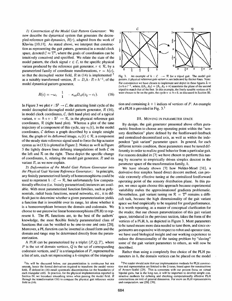
In Figure 3 we plot r : §1 --+ C, the attracting limit cycle of the model decoupled decoupled model pattern generator, R (16), in model clock coordinates, C, (left hand plot) and of a typical variant, v = h 0 v : §1 --+ R, in the physical reference gait coordinates, R (right hand plot). W hereas a plot of the time trajectory of a component of this cycle, say VI (t), in the model coordinates, C defines a graph described by a simple straight line, the graph of its deformed image, VI (t) E R, a component of the steady state reference signal used to force the hip actuator system as in (13) is plolted in Figure 2. Notice as well in Figure 3 the lightly drawn lines defining triangulations of both C on the left and R on the right. These depict the specific change of coordinates, h, relating the model gait generator, R and its variant R, as we now explain.
2) Deformation of the Model Gait Pattem Generator into the Physical Gait Variant Reference Generator:: In principle, any finitely parameterized family of homeomorphisms could be used to represent h : C --+ R, but unfortunately few computationally effective (i.e. finitely parametrized) instances are available. With most parameterized function families, such as polynomials, radial basis functions, neural networks, etc., it is difficultjust to determine whether a given parameterization yields a function that is invertible over its range, let alone whether it is a homeomorphism between the domain and codomain. We choose to use piecewise linear homeomorphisms (PLH) to represent h. The PL functions are, to the best of the authors' knowledge, the most flexible finitely parameterized class of functions that can be verified to be one-to-one and onto [28]. Moreover, a PL function can be inverted in closed form and the domain and range may be determined directly from the parameterization.
A PLH can be parameterized by a triplet (P, Q, T), where P is the set of domain vertices, Q is the set of corresponding codomain vertices, and T is a triangulation of P, represented as a list of sets, each set representing a k-simplex of the triangula-
z As will be discussed below. our parametrization is continuous but not smooth, hence the fonnal derivatives required to transfonn the model vector field, R defined in (16) entail systematic discontinuities (at the boundaries of each triangular cell). In practice. for the physical implementation reported i� Section IV. we introduce smoothing terms when passing the model field. R through the transfonnation (16) to compute the physical gait reference vector field in (14).
Fig_ 3. An example of h : C __ n for a tripod gait. The model gait pattern, ii physical reference gait variant v, are indicated by thicker Iines_ N3te: For convenience we have chosen to implement and depict in these figures h = 10 h 0 1-1, where, I(OJ, Oz) = (01,02 + 1l') translates the phase of the second tripod to match that of the first. In this example, the freely tunable vertices of h were chosen to lie on the gaits. the cycle v "= h 0 ii, as discussed in S ection III.
tion and containing k + 1 indices of vertices of P. An example of a PLH is provided in Fig. 3.3
III. MOVING IN PARAMETER SPACE By design , the gait generator presented above offers para
metric freedom to choose any operating point within the "sensory distribution" plane defined by the feedforward-feedback and centralized-decentralized axis, as well as within the independent "gait variant" parameter space. In general, for each different terrain condition, these parameters must be luned differently in order to realize good behavior from a particular gait. For reasons detailed in [7] we have chosen to perform this tuning by recourse to empirically driven simplex descent in the parameter space of the transformation family, h.
We have already shown [7] how Neider-Mead [31], a derivative-free simplex based direct descent method, can provide extremely effective tuning at the centralized feedforward operating point of the sensory distribution plane. In this paper, we once again choose this approach because experimental variability makes the approximationof gradients problematic. Nevertheless , gait variant tuning on R = ']['6 remains a difficult task, because the high dimensionality of the gait variant. space we find empirically to be required for good performance. It is worth repeating, as a maHer of conceptual clarification for the reader, that our chosen parametrization of this gai t variant space, introduced in the previous section, takes the fonn of the vertices of a PLH, h, as depicted in Figure 3. More parameters to be tuned means more data needed to tune them, and since experiments are expensive with respect to robot and operator time, we have used biological insight and our working experience to reduce the dimensionality of the tuning problem by "slaving" some of the gait variant parameters to others, as will now be described.
Rather than using a completely free choice of the PLH pa� rameters in h. the domain vertices can be placed on the model
3The reader should note that our implementation methods for PLH construction and representation are limited to the 2-torus, based upon the constructions of Aronov-Seidel [29]. This is consonant with our present focus on virtual bipedal gaits, but in the long run, it will be important to develop simple constructive methods for defining and checking computationally effective PLH constructions on torii of general dimension. For more on PLH representations and compu tation. see [28), [30].
684
gait and tile space triangulated such that edges of the triangulation lie entirely along tile model gait. In this case, the generated gait will be given explicitly by the range vertices corresponding to the domain vertices on the model gait. Figure 3 shows an example of this. Placing the vertices in this way confers two benefits. First, the number of parameters in h is held to a bare minimum to represent a particular gait. Second, since the gait is made apparent, (his representation offers a handle for applying operator intuition in the selection of initial parameter sets. In fact in the virtual biped case, if the gait and the model gait are specified, the computation introduced in [29] can be applied directly to generate a piecewise linear homeomorphism that maps the mo del gait into the gait.
IV. EXPERIMENTAL RESULTS
In this section we discuss the preliminary results of implementing this coordination control system on RHex. We conduct two sets of tests. The first addresses RHex's en.ergy efficiency over both a l inoleum floor and a rough bed of bricks. The second set of experiments assesses the relative benefits of coordination when traversing a modified version of the brick bed as the terrain is made progressively more "extreme".
A. Robot eifeciellcy
As a convenient scalar valued surrogate for endurance we use specific resistance,
( 17)
where Pav is the average power4 Tn is the mass of the robot, 9 is acceleration of gravity, and Vav is average velocity. We run our tuning algorithm in conjunction with our coordination system to find "good" parameter settings for each terrain. The specific resistance of the resultant gait is then compared to the previous best open-loop gait.
1) Linoleum: To compare specific resistance on linoleum to
the carefully tuned open-loop system [7] we run the NclderMead based optimization on the larger parametrization suggested in this paper. A descen.t consists of several hundred ex.periments over an 8m linoleum course. Each experiment in-
. volves two such runs where the cost function is then averaged. The parameters being tuned include the knot points defining the trajectory in Figure 2, and the gains associated wilh the control equations. As can be seen in table 1 after running a number of
descents the final specific resistance was 0.72 this represents a 15% improvement over the open-loop gait.
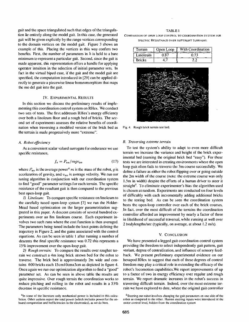
2) Rough terrain: To compare the results over rougher terrain we construct a 4m long brick strewn bed for the robot to traverse. The brick bed is approximately 2m wide and contains 600 bricks each 15cml Ocmx5cm as depicted in figure 4. Once again we run our optimization algorithm to find a "good" parameter set. As can be seen in above table the results are quite impressive. Over rough terrain the coordination works to reduce pitching and rolling in the robot and results in a 53% decrease in specific resistance,
41n some of the literature only mechanical power is included in this calculation. Other authOrs report the total power (which includes power for the onboard computation and inefficiencies in the electronics), as we do here.
TABLE l COMI'ARISON 01' OPEN LOOP CONrROL TO COORDINATION SYSTEM FOR
SPEC/He RES/STANCE OVER DifFERENT TERRAINS.
Terrain Open Loop 1/ With Coordination
Linoleum
II 2.2 0.87 0.73
Bricks 4 .7
Fig. 4. Rough brick terrain test bed.
B. Traversing extreme terrain
To test the system's ability to adapt to even more difficult terrain we increase the variance and height of the brick exper
imental bed (naming the original brick bed "easy"). For these tests we are interested in creating environments where the open loop gait often fails to traverse the 3m course successfully. We define a failure as either the robot fl ipping over or going outside the 2m width of the course (note: the extreme course was only 1 .5m in width) despite the efforts of a human driver to steer it straight5. To eliminate experimenter's bias the algorithm used is chosen at random. Experiments are conducted on four levels
of difficultly with each incrementally adding additional bricks to the testing bed. As can be seen the coordination system bests the open-loop controller over each of the brick courses.
. In fact, over the most difficult of the terrains the coordination controHer afforded an improvement by nearly a factor of three in likelihood of successful traversal, while running at well over 2 bodylengths/sec (typically, on average, at about 1 .2 mls).
V. CONCLUSION We have presented a legged gait coordination control system
providing the freedom to select independently gait pattern, gait variant, degree of centralization, and influence of sensory feedback. We present preliminary experimental evidence on our hexapod RHex to suggest that each of these degrees of control freedom may play a critical role in extending the efficacy of the robot's locomotion capabilities.We report improvements of up to a factor of two in energy efficiency over regular and rough terrain. We report dramatic increases in the robot's success in traversing difficult terrain. Indeed, over the most extreme terrain we have eKplored to date, where the original gait controller
5 Steerin g our robot involves changing the gait parameters on one side of the robot as compared to the other. Human steering i nputs were introduced at the motor control level, hidden from the coordination system
685
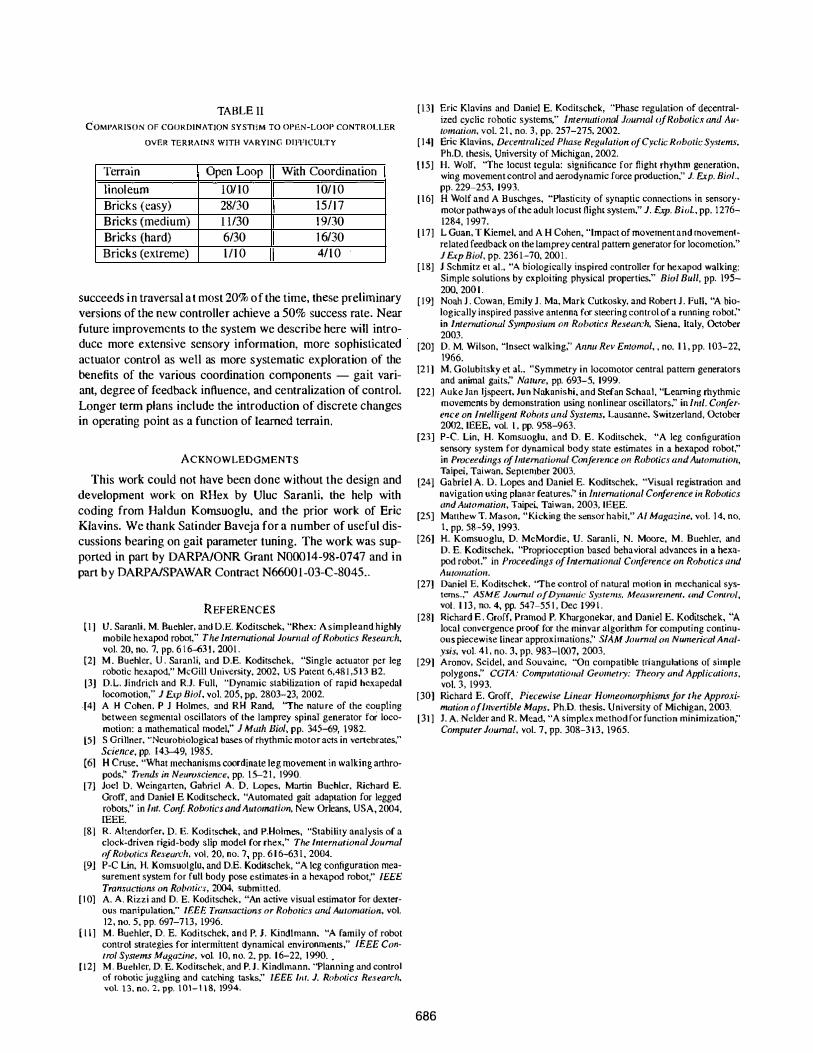
TABLE II COMPARISON OF COORDINATION SYSTr}M TO OPEN-LOOP CONTROLLER
OVER TERRAINS WITH VA RYING DIFFICULTY
Terrain I Open Loop II With Coordination
linoleum 10/ 10 101 1 0 Bricks (easy) 28/30 1511 7 Bricks (medium) 1 1130 \ 9/30 Bricks (hard) 6130 1 6/30 Bricks (extreme) 111 0 4/10
succeeds i n traversal a t most 20% o f the time, these preliminary versions of the new controller achieve a 50% success rate. Near future improvements to the system we describe here will introduce more extensive sensory information, more sophisticated actuator control as well as more systematic exploration of the benefits of the various coordination components - gait variant, degree of feedback influence, and centralization of control. Longer term plans include the introduction of discrete changes in operating point as a function of learned terrain.
ACKNOWLEDGMENTS
This work could not have been done without the design and development work on RHex by Uluc Saranli, the help with coding from Haldun Komsuoglu, and the prior work of Eric Klavins. We thank Satinder Baveja for a number of useful discussions bearing on gait parameter tuning. The work was supported in part by DARPNONR Grant NOOO14-98-0747 and i n
part b y DARPNSPAWAR Contract N66001-03-C-804S . .
REFERENCES [ I ] U. Saranli. M. Buehler, and D.E. KOdi tschek, "Rhex: A simple and highly
mobile hexapod robot," The International Journal of Robotics Research.
vol. 20, no. 7. pp. 6 1 6--63 1 , 2001 . [2] M . Buehler. U . Saranli, and D.E. Koditschek. "Single actuator per leg
robotic hCJ<apod." McGill University. 2002. US Patcnt 6,48 1 ,5 1 3 B2. [3J D.L. Jindricl1 and RJ. FUll, "Dynamic stabilization of rapid hexapedal
locomotion," J Exp Biol, vol. 205, pp. 2803-23, 2002. .[4] A H Cohen, P J Holmes. and RH Rand, "The nature of the coupling
between segmental osci llators of the lamprey spinal generator for locomotion: a mathematical model," J Math Bioi. pp. 345-69, 1 982.
[5] S Grillner. "NeurObiological bases of rhythmic motor acts in vertehrates."
Science, pp. 143-49, 1985. [6] H Cruse. "What mechanisms coordinate leg movement in walking arthro
pods;' Trends in Neuroscience, pp. 1 5-2 1 . 1990. [7] Joel D. Weingarten, Gabriel A. D. Lopes. Martin Buehler. Richard E.
Groff, and Daniel E Koditscheck. "Automated gait adaptation for legged robots." in 1111. Conf Robmics alld Auromation, New Orleans, USA, 2004. IEEE,
[8] R. Altendorfer, D. E. Koditschek, and P.Holmes, "Stability analysis of a clock-driven rigid-body slip model for rhex," The International Journal of Robotics ReJ·earclr. vol. 20, nO . .." pp. 6 1 6-63 1 . 2004.
[9] P-C Lin. H. Komsuolglu, and D.E, Koditschek, "A leg configuration measurement system for full body pose estimates·in a hexapod robot," IEEE Transac/ions on Robmics. 2004, submitted.
[ 1 0] A. A. Rizzi and D. E. Koditschek. "An active visual estimator for dexterous manipulation," IEEE Tramactions or Robotics and Automation. vol. 12, no. 5. pp. 697-713, 1996.
[ l l ] M. Buehler, D. E. Koditschek, and P. J. Kindlmann. "A family of robot control strategies for intermittent clynamical environments," IEEE Control Systems Maga:ille. vol. 10. no. 2. pp. 1 6-22. 1 990 . •
[J 2] M. Buehler. D. E. Koditschek. and P. J . Kindlmann, "Planning and control of rObotic juggling and catching tasks;' IEEE 1m. J. Robotics Research, vol. 13, no. 2. pp. 1 01-1 1 8, 1994.
[ 1 3] Eric Klavins and Daniel E. Koditschek, "Phase regulation of decentralized cyclic robotic systems." International Joun/al (if Robotics and AuIOmntion. voL 2 1 , no. 3 , pp. 257-275. 2002.
[ 1 4] Eric Klavins, DeClmlrali::.ed Phase Regulation afCyclic Robotic Systems. Ph.D. thesis. University of Michigan, 2002.
[ 1 5] H. Wolf, "rhe locust tegula: significance for flight rhythm generation. wing movement control and aerodynamic force production." J. Exp. Bioi., pp. 229-253, 1993.
[ 1 6J H Wolf and A Buschges, "Plasticity of synaptic connections in sensorymotor pathways of the adult locust flight system," J. Exp. Biul . • pp. 1 276-1284. 1 997.
[ 17J L Guan. T Kiemel. and A H Cohen, "Impact of movement and movementrelated feedback on the lamprey central pattern generator for locomotion." J Exp Bioi. pp. 236 1-70. 200 I .
[ 1 S] J Schmitz et aI., "A biologkally inspi red controller for hexapod walking: Simple solutions by exploiting physical properties." Bioi Bull, pp. 195-200. 200 1 .
[ I 9J Noah J . Cowan, Emily J. Ma. Mark Cutkosky, and Robert J. Full, "A biologically inspired passi ve antenna for steering control of a running robot;' in International Symposium 011 Roba/ics Rese<m:h, Siena. Italy, October 2003.
[20] D. M. Wilson. "Insect walking;' Annu Rev Entonw/, . no. I I , pp. 103-22. 1966.
[2 1 ] M. Golubitsky et al.. "Symmetry in locomotor central pattern generators and animal gaits;' Nature, pp. 693-5. 1999.
[22] Auke Jan Ijspeert, Jun Nakanishi, and Stefan Schaal. "Learning rhythmic movements by demonstration using non linear oscillators;' in Iml. Conference on InTelligent Robots and Systems, Lausanne, Switzerland. October 2002. IEEE, vol. I , pp, 958-963.
[23] P-C. Lin, H. Komsuoglu, and D, E. Koditschek. "A leg configuration sensory system for dynamical body state estimates in a hexapod robot;' in Proceedings of Illtemotional Conference on Robotics and Automation, Taipei, Taiwan, September 2003.
[24] Gabriel A. D. Lopes and Daniel E. Koditschek. "Visual registration and naVigation u�ing planar features;' in Imernational Conference in Roborics and Automation. Taipei. Taiwan, 2003, IEEE.
[25] Mauhew T. Mason. "Kicking the sensor habit." AI Magazine, vol. 1 4. na. l , pp. SS-59, 1993,
[26] H. Komsuoglu, D. McMordie. U. Saranli, N. Moore, M. Buehler. and D. E. Koditschek, "Proprioception based behavioral advances in a hexapod robot." in Proceedillgs of Intemational Conference 011 Robotics alld AutouUl/ioll.
[27] Daniel E. Koditschek. "The control of natural motion in mechanical systems .... ASME Juurnal of Dynamic Systems. Mew·urement. 'IIJd Control, vol . 1 1 3 , no. 4, pp. 547-55 1 , Dec 1 99 1 .
[28] Richard E . Groff, Pramod P. Khargonekar. and Daniel E. Koditschek, "A local convergence proof for the minvar algorithm for computing continuous piecewise linear approximations," SIAM Journal on Numerical Analysis, vol. 4 1 . no, 3, pp, 983-1007, 2003.
[29] Aronov, Seidel, and Souvaine, "On compatible triangulations of simple polygons:' CGTA: CompJltatiOlUll Geometly: Theory and Applications. vo1. 3, 1993.
[30J Richard E. Groff, Piecewise Linear Homeomorphism.v for the Approximntion of Invertible Maps. Ph.D. thesis, University of Michigan, 2003.
[31J J. A, Neider and R. Mead, "A simplex method for function minimization," COInpc/ler Journal. vol. 7, pp. 308-3 1 3, 1965.
686