A Framework for the Automation of LTE Physical
15
Noname manuscript No. (will be inserted by the editor) A Framework for the Automation of LTE Physical Layer Tests Felipe A. P. de Figueiredo · Fabiano Mathilde · Dick Carrillo · Ingrid Moerman Received: date / Accepted: date Abstract The Long Term Evolution (LTE) network architecture comprises, among other elements, the Base Station (eNodeB), which provides and con- trols the air interface. ENodeB protocol stack is composed of different layers, each one with specific purpose. In terms of air interface performance, the most critical layers of an eNodeB are the physical layer (PHY) and the medium access control Layer (MAC). Both must operate on precise timing basis, cor- responding to a frame duration of 1 ms. Because of this requirement, PHY layer developers need an effective test architecture, capable to follow time response policies. This article proposes an automated test framework for eN- odeB’s physical layer development, comprising procedures for checking data integrity, stability and performance. This framework is based on a simplified LTE MAC layer, which operates as a software element that communicates di- rectly with the physical layer and performs mapping procedures between log- ical and physical channels, reception and transmission of physical layer data, user data scheduling and data exchange with mobile terminals. All above men- tioned procedures are performed with no further dependency on other LTE network elements, thus providing a stand-alone test framework. Keywords LTE, · Physical Layer · Test Framework · MAC Felipe A. P. de Figueiredo · Ingrid Moerman Ghent University - imec, IDLab, Department of Information Technology, Ghent, Belgium. Fabiano Mathilde Eldorado Institute, Campinas, Brazil Dick Carrillo CPqD - Research and Development Center on Telecommunications, Campinas, Brazil. E-mail: [email protected]
Transcript of A Framework for the Automation of LTE Physical
Noname manuscript No.(will be inserted by the editor)
A Framework for the Automation of LTE PhysicalLayer Tests
Felipe A. P. de Figueiredo · FabianoMathilde · Dick Carrillo · IngridMoerman
Received: date / Accepted: date
Abstract The Long Term Evolution (LTE) network architecture comprises,among other elements, the Base Station (eNodeB), which provides and con-trols the air interface. ENodeB protocol stack is composed of different layers,each one with specific purpose. In terms of air interface performance, the mostcritical layers of an eNodeB are the physical layer (PHY) and the mediumaccess control Layer (MAC). Both must operate on precise timing basis, cor-responding to a frame duration of 1 ms. Because of this requirement, PHYlayer developers need an effective test architecture, capable to follow timeresponse policies. This article proposes an automated test framework for eN-odeB’s physical layer development, comprising procedures for checking dataintegrity, stability and performance. This framework is based on a simplifiedLTE MAC layer, which operates as a software element that communicates di-rectly with the physical layer and performs mapping procedures between log-ical and physical channels, reception and transmission of physical layer data,user data scheduling and data exchange with mobile terminals. All above men-tioned procedures are performed with no further dependency on other LTEnetwork elements, thus providing a stand-alone test framework.
Keywords LTE, · Physical Layer · Test Framework · MAC
Felipe A. P. de Figueiredo · Ingrid MoermanGhent University - imec, IDLab, Department of Information Technology, Ghent, Belgium.
Fabiano MathildeEldorado Institute, Campinas, Brazil
Dick CarrilloCPqD - Research and Development Center on Telecommunications, Campinas, Brazil.
� E-mail: [email protected]

2 Felipe A. P. de Figueiredo et al.
1 Introduction
The LTE corresponds to one of the most important current mobile commu-nication technologies, and has been standardized by the Third GenerationPartnership Project (3GPP) [1,2]. LTE was developed to meet the growingdemands of data transmission at high speed, also supplying voice transmis-sion. The main advantages of LTE are based on new specifications for radioaccess network (RAN), achieving high data rates, low latency transmissionand high spectral efficiency. Such benefits are only possible due to the archi-tecture defined for the Radio Access Network (RAN), comprising base stations(eNodeB) and user equipment (UE) [1–3].
The eNodeB’s protocol architecture comprises several layers [3]. Each layerhas a different purpose, according to its operating protocol, and serves differenttiming requirements [4–8]. Due to advanced communication technologies em-ployed in LTE, such as Orthogonal Frequency Division Multiplexing (OFDM)and Multiple Input Multiple Output (MIMO), some layers become critical forsystem performance, such as the Physical Layer (PHY), which is often devel-oped as a hardware-level element [9–11]. The second critical layer of eNodeBstack is the Medium Access Control Layer (MAC), which is developed as ahigh-performance and real-time software element due to its direct communi-cation with physical layer (PHY) [7]. Because of interoperability nature ofLTE architecture, PHY and MAC layers are developed by different vendors,generating an integration effort. Based on this fact, this article focuses on atest framework that consists of a simplified MAC layer (MAC) targeting PHYlayer conformance, performance and integration tests [11]. Such architectureis designed to operate independently by upper layers, as a stand-alone solu-tion. In order to achieve it, a simplified and light-weight MAC layer (MACLITE) has been designed to emulate a real MAC layer, covering throughputperformance, stability, data integrity and conformance test cases [11]. It hasbeen noticed that MAC LITE is extremely useful for PHY development.
The paper is organized as follows. Section 2 presents the motivation forcreating the test framework for physical layer development. Section 3 providesa detailed explanation of eNodeB protocol stack and the architecture proposedfor testing, while Section 4 presents the main use cases. Section 5 presents theconclusions and references.
2 Motivation
In September 2012, 3GPP started a Working Item to standardize the fre-quency bands 450-470 MHz [12]. This initiative aimed at taking advantageof RF propagation characteristics in lower frequency bands, based on a newLTE and LTE-Advanced profile [12,13]. This profile is useful in scenarios withlarge coverage requirements in sparsely populated areas. The CPqD Foun-dation supported 3GPP in this task, by determining new channel schemes,solutions for coexistence and radio transceiver parameters suitable for LTE

A Framework for the Automation of LTE Physical Layer Tests 3
and LTE-Advanced operation in the 450 MHz band. The standardization pro-cess finished in September 2013, and band 450-470 MHz has been designatedas the new 3GPP Band 31.
In parallel to 3GPP activities, the Communications Ministry has beenworking on a way to introduce new broadband Internet services in Brazil [14,15]. In this sense, a paradigm shift occurred in May 2010, when the NationalBroadband Plan (PNBL) recommended the use of the frequency band 225-470MHz [13]. One of PNBL guidelines was to leverage broadband Internet pene-tration in Brazilian territory, specifically in rural areas, where about 30 millionBrazilians still lack access to this type of service. Also in 2010, the NationalTelecommunications Agency (ANATEL) has allocated the frequency bands451-458 MHz and 461-468 MHz to serve as downlink and uplink, respectively,for fixed and mobile radio services operating on Division Duplex mode [13].
Furthermore, ANATEL auctioned the Band 31 licenses in June 2012. As aresult, Band 31 is now available to all the major telecommunications operatorswithin in the Brazilian market. It is worth mentioning that the winning oper-ators must meet the coverage and capacity targets defined by ANATEL [13],while the adoption of specific technology associated with these licenses is open.It is believed that the operators holding licenses will most likely adopt LTEtechnology to take advantage of superior RF features of Band 31 for providingbroadband access [12–15].
LTE implementation in Band 31, besides providing wider coverage area persector, imposes many technical challenges, mostly related to RF characteris-tics. In order to ensure Band 31 benefits are achieved, eNodeBs require spe-cific technology development, especially related to RF components and PHYfeatures. In this context, a stand-alone framework is proposed, for PHY con-formance, stability, data integrity and performance testing. It is composed of asimplified MAC layer (MAC LITE) and main procedures for automated test-ing. The next section will provide more details of LTE layers and the proposedtesting framework.
3 Fundamentals of LTE Layers
This section is composed of three distinct parts. The first part discusses the de-tails of eNodeB architecture, showing all its main features [16–19]. The secondpart discusses in detail the main features of the proposed testing framework,while the third part describes its use cases.
3.1 eNodeB architecture
In LTE and LTE-Advanced systems, the eNodeB protocol stack is composedof layers and sub-layers as illustrated in Figure 1. Each layer performs specificfunctionalities [1], as described below:

4 Felipe A. P. de Figueiredo et al.
Fig. 1 eNodeB described in 3GPP Standard.
1. Radio Resource Management (RRM): this sub-layer of Layer 3 isresponsible for management and efficient usage of radio frequency resources[20]. The RRM supports mechanisms and algorithms for controlling airinterface resource, such as power transmission, resource allocation for users,data rates, modulation schemes and error control. All these strategies aimat better usage of limited radio frequency spectrum;
2. Radio Resource Control (RRC): this sub-layer of Layer 3 is responsiblefor establishment, maintenance and control of connections between userequipment and base stations [8];
3. Packet Data Convergence Control (PDCP): this sub-layer of Layer 2is responsible for compression and decompression of user data encapsulatedby IP protocol, as well as checking data integrity or insert redundancies[5];
4. Radio Link Control (RLC): this sub-layer of Layer 2 is responsible fordata packets transference to PDCP layer. The packets containing user datacomes from PDCP layers and are encapsulated in RLC packets. Dependingon channel conditions, system configuration and packet length, RLC splitsoriginal packet into multiple packets, transmitting them according to thesystem transmission capacity. RLC is also responsible for reordering, con-

A Framework for the Automation of LTE Physical Layer Tests 5
solidation and removing duplicate data packets, which were originated byaccess layer [6];
5. Medium Access Layer (MAC): this sub-layer of Layer 2 performs themapping between transport and physical channels. It is also responsiblefor resource block scheduling and error correction by selective repetitionsystem, also named HARQ (Hybrid ARQ) [7]. The main transport channelsare [21]:
(a) Broadcast Channel (BCH): downlink signaling channel used fortransmitting broadcast messages, and sending information system toall handsets into eNodeB coverage region;
(b) Downlink Shared Channel (DL-SCH): downlink signaling channelused for transmitting data information to mobile terminals;
(c) Uplink Shared Channel (UL-SCH): uplink data channel, used totransmit data information from mobile terminals to eNodeB;
(d) Random Access Channel (RACH): uplink signaling channel usedfor transmitting messages related to random access channel proceduresbetween mobile terminals and eNodeBs.
6. Physical Layer (PHY): this layer performs wireless communication withLTE mobile devices, as well as the interface with upper layers [4,10,22]. Itsupports different transmission characteristics, according to data transmis-sion type. The transmission characteristics are defined by so-called physi-cal channels, which receive data from transport channels [10]. Due to thegreat complexity and necessity of low-latency communication of physicalchannels, such layer is usually developed using hardware elements such asFPGA, DSP or ASIC. Each LTE physical channel has a specific purpose,as per the following description [10,17]:
(a) Physical Broadcast Channel (PBCH): Control channel responsibleof transporting broadcast messages. It transmits system information toall mobile terminals. It is part of downlink channel structure;
(b) Physical Control Format Indicator Channel (PCFICH): Con-trol channel responsible to transmit mobile terminals information re-lated to format of control channel transmission (PDCCH). It is part ofdownlink channel structure;
(c) Physical Downlink Control Channel (PDCCH): Control channelresponsible of transmitting resource block allocation, power control andpaging. It is part of downlink channel structure;
(d) Physical Hybrid ARQ Indicator Channel (PHICH): Controlchannel responsible to transmit HARQ information to mobile termi-nals. It is part of downlink channel structure;
(e) Physical Downlink Shared Channel (PDSCH): this channel isresponsible to transmit data information from eNodeB to mobile. Thisis the physical channel with higher throughput. It is part of downlinkchannel structure;
6 Felipe A. P. de Figueiredo et al.
(f) Physical Uplink Control Channel (PUCCH): Control channelresponsible to transmit signal information related to scheduling request.It is part of uplink channel structure;
(g) Physical Uplink Shared Channel (PUSCH): Channel responsibleto transmit data information from mobile terminals to eNodeBs. It ispart of uplink channel structure;
(h) Physical Random Access Channel (PRACH): Channel responsi-ble of sending random access preamble that mobile terminal transmitsto eNodeB in unsynchronized mode. Such preamble is used so that theUE can synchronize timing with the eNodeB. It is part of uplink channelstructure.
All layers discussed above are necessary for complete operation of an eN-odeB. The upper layers of the LTE network have not been mentioned sincethey are not part of this article’s scope. The layers above the physical layer(RRM, RRC, PDCP, RLC and access layer) are often developed as real timeembedded software elements, because of requirements such us flexibility, scal-ability, upgradeability, among others. In case of LTE, physical layers oftenuse well-structured interface for communication with the upper layers, such asthe well-known Femto API [23] (a direct reference to small and medium-sizedstations, also known as Femto Cells). Such interface is based on standardized(PHY) and access layer (MAC) messages. The framework described in thisarticle uses this protocol as a reference for communication and operation ofphysical layer in testing phase. In the next section it is explained in detail thearchitecture features for testing proposed by the article.
3.2 Simplified MAC Layer Architecture
As mentioned in the introductory section, the proposed architecture has beendesigned as a stand-alone framework for PHY testing, with no dependency onupper layers described in the previous section. In order to make this possible,the creation of a centralizing element was necessary to carry out the maintest procedures based on the user-defined settings. Such software element con-taining procedures for master boot, injection, recovery of configuration dataparameters. These actions are based on procedures described by the FemtoForum API interface [23], since it also includes the main operating and start-ing procedures of commercial physical layers. For the full operation of suchelement, the architecture relies on a few layers or intermediate components.Such elements are described in Figure 2.
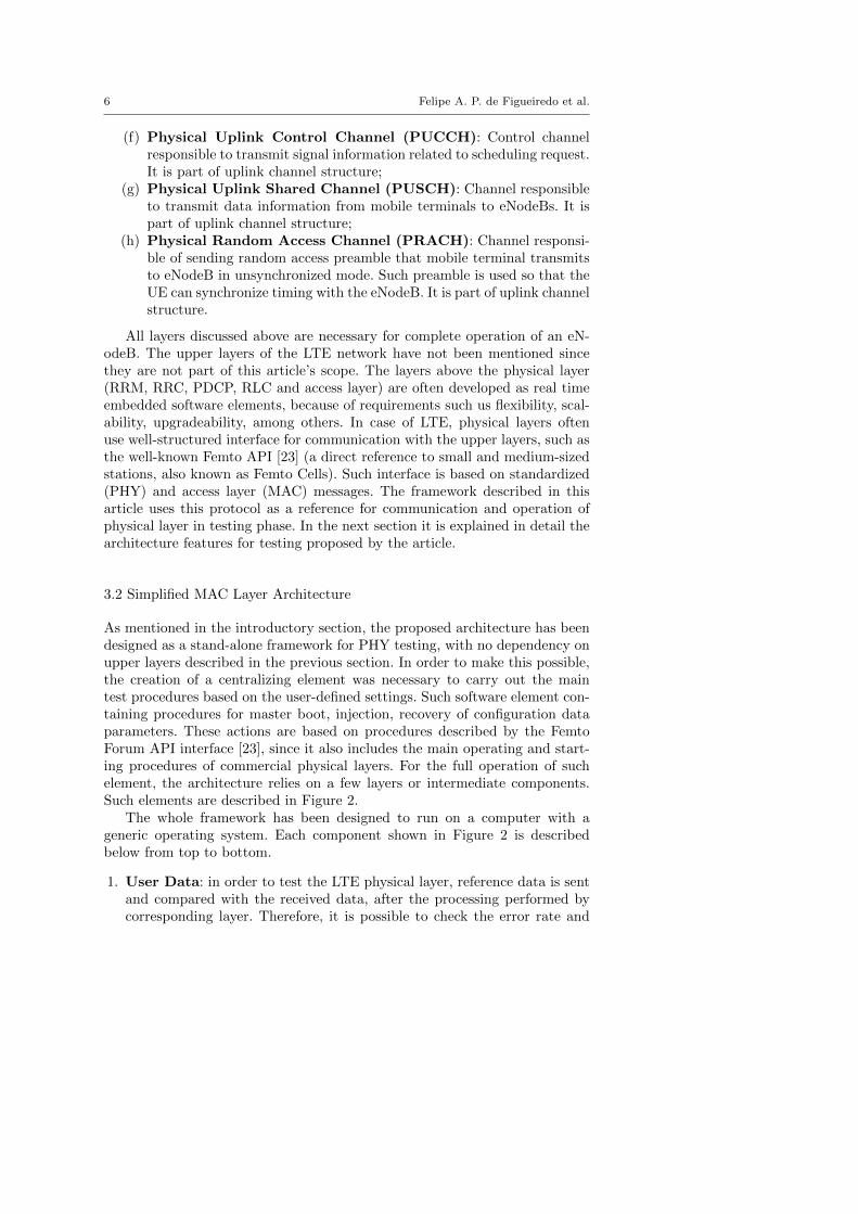
The whole framework has been designed to run on a computer with ageneric operating system. Each component shown in Figure 2 is describedbelow from top to bottom.
1. User Data: in order to test the LTE physical layer, reference data is sentand compared with the received data, after the processing performed bycorresponding layer. Therefore, it is possible to check the error rate and
A Framework for the Automation of LTE Physical Layer Tests 7
Fig. 2 Proposed Framework Architecture.
the system throughput as a whole. The framework comprises an abstrac-tion at the operating system level, where data is sent and received througha virtual network interface, thus enabling data injection from any appli-cation that supports communication via network, facilitating the testingprocedure;
2. Virtual Ethernet Interface: the purpose of this interface is to collectreference data and injecting it into the system. All modern operating sys-tems support such technology, where the injection of reference data in thesystem is transparent to the user. These interfaces are addressed by Inter-net Protocol (IP) stack and facilitate the process of sending and receivingdata. Thus, for an application to send or receive data, it only needs toaddress the data packets with the IP address of the desired interface;
3. FIFO (First In First Out): due to the large data flow that must besupported by a LTE physical layer, the proposed framework provides ahigh-capacity data queue to avoid bottlenecks in both the acquisition andconsumption of such data. The data queue also ensures that they can beconsumed at a data rate different from that used during the generation.Virtual network interfaces allow their data to be redirected to other appli-cations, such functionality is known as Bridge (or data bridge). Through abridge, the data received or sent to the virtual network interface architec-ture is captured/received by a FIFO, from where they can be consumedby the simplified medium access control layer (MAC LITE);

8 Felipe A. P. de Figueiredo et al.
4. Simplified MAC (MAC LITE): it is the central mechanism of the pro-posed framework. It acts as a simplified access layer, performing all startupprocedures and execution of stability tests, following the standards pointedby the Femto Forum API. Through a series of parameters passed to thislayer via a data base (not detailed in Figure 2), it performs both the datainjection and operation of the physical layers attached to it. The simplifiedaccess layer supports parallel operation of multiple physical layers, whichenables testing carrier aggregation (CA) technology, a key LTE-Advancedfeature. In this technology, each carrier is generated by a different physicallayer, being the role of the MAC LITE to define of which data is sent toeach one of the attached physical layers.
5. Physical Layer Abstraction: it was developed so that different commu-nication interfaces between the MAC and PHY are supported. The com-munication interfaces adopted for formatting the messages and proceduresis part of the Femto Forum API (FAPI) reference. However, FAPI doesnot define any protocol for sending the messages to the physical layer,and therefore, UDP sockets, shared memory, PCI, among others, can beused to that end. The proposed framework provides abstraction on spe-cific messages transmission to the LTE physical layer, leaving the messagepackaging to send or receive data up to the developer;
6. Physical Layer: this is the LTE physical layer under test. It may becommercial or under development solutions (the way the framework be-haves for each type of physical layer will be explained in more detail inthe following sections). Such physical layer must be compatible with thecommunication protocol defined by the Femto Forum API reference [23].As previously mentioned, the way data messages are transported is notpart of the scope of this article, being directly related to the technologyadopted at the physical layer.
The process of communication between the upper layers and the physicallayer must meet critical requirements of timing and minimum throughput.Such requirements must be tested during the integration process, and can alsobe done through the proposed architecture. The following section will detailthe main use cases of the proposed architecture.
3.3 Key Uses for the Proposed Framework
The principal users of the proposed framework can be divided into two maingroups:
– Developers integrating physical layer with other layers;– Developers who are creating physical layers based on re-configurable or
related hardware.
The main difference between the two groups of users lies in the fact thatfor the first group it is supposed that the physical layer is fully functional, and
A Framework for the Automation of LTE Physical Layer Tests 9
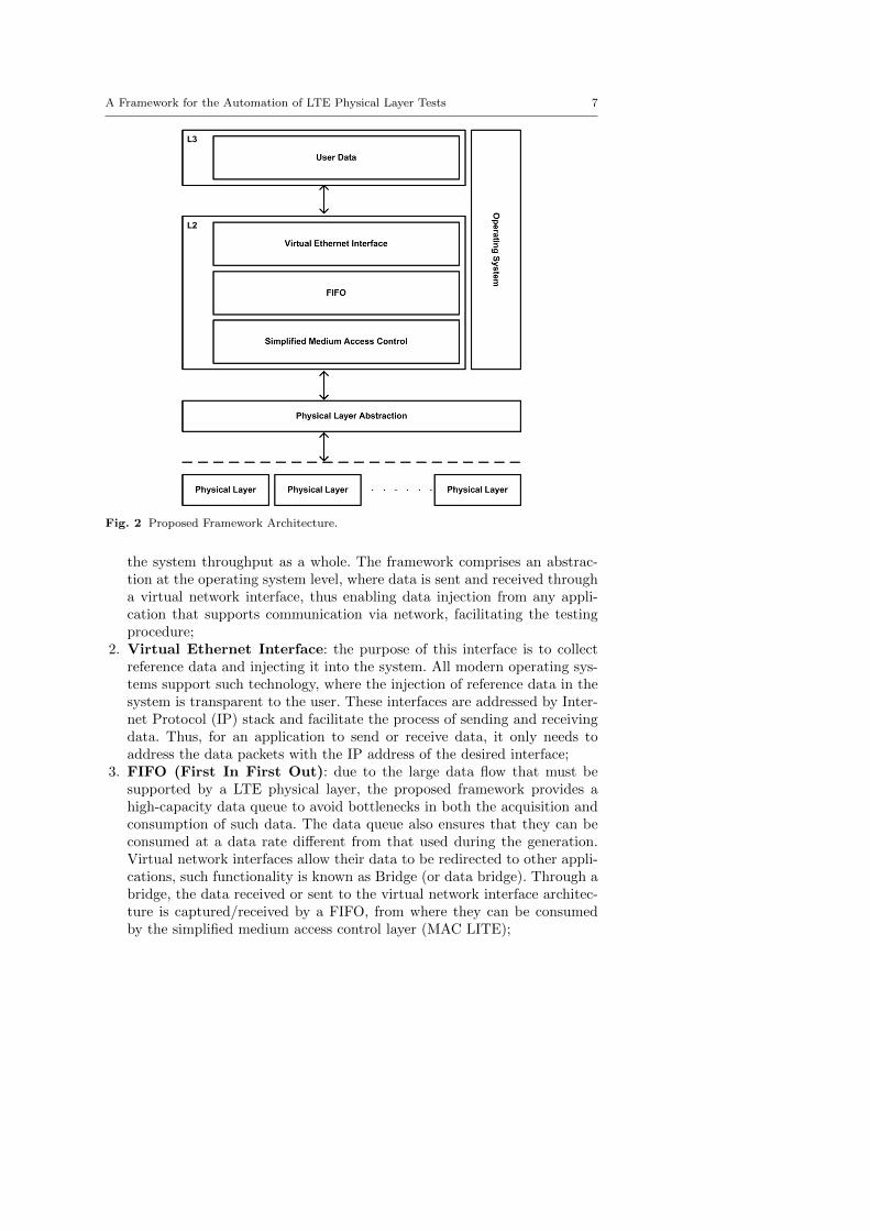
in this case, the framework is only used to test the messaging protocol. Figure3 shows a basic environment based on the proposed framework for such usergroups. It should be noted that a tool for capturing and analyzing messages isneeded (e.g., Ethereal tool). This tool is not part of the scope of the proposedarchitecture as it depends on the way messages are exchanged between layers.Through this tool, users can evaluate the behavior of the physical layer undertest, leaving the developer to adapt the access layer according to such behavior.These tests are useful to check problems in both timing and order of receivedmessages exchanged between the physical and access layers. It starts from theassumption that the physical layer uses the Femto Forum API protocol forcommunication.
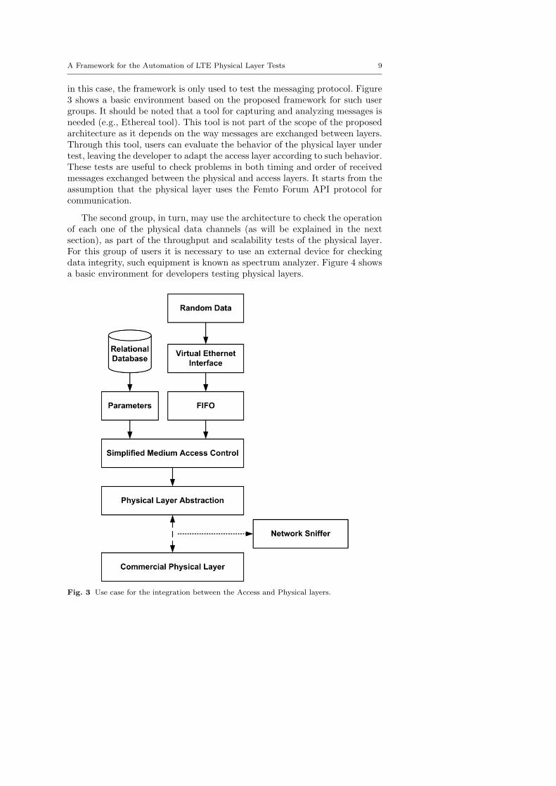
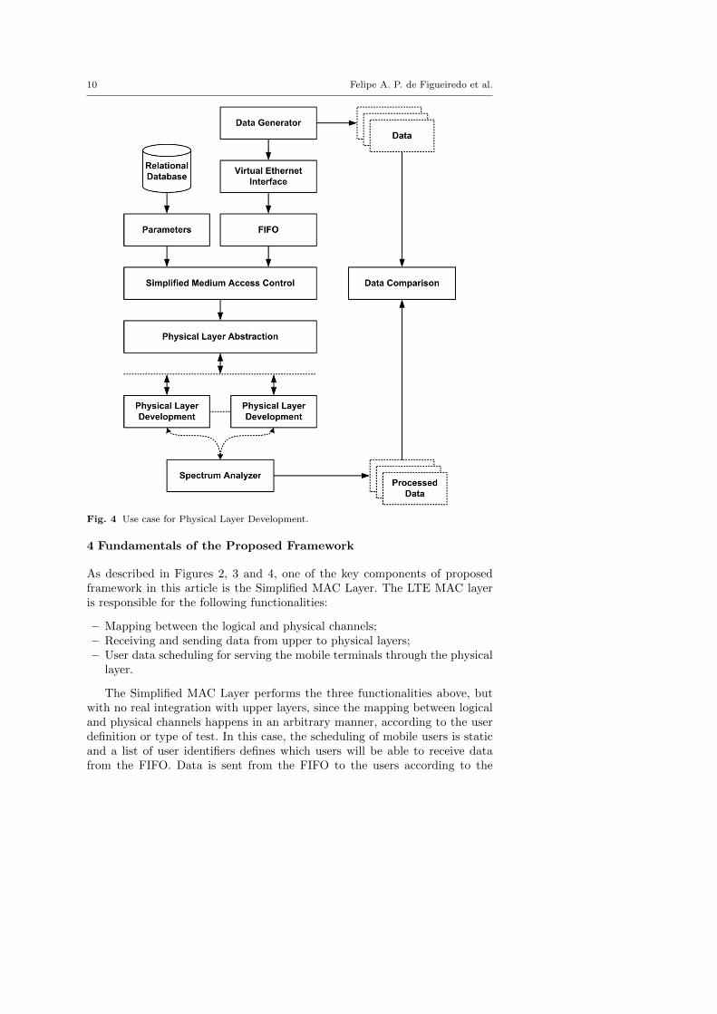
The second group, in turn, may use the architecture to check the operationof each one of the physical data channels (as will be explained in the nextsection), as part of the throughput and scalability tests of the physical layer.For this group of users it is necessary to use an external device for checkingdata integrity, such equipment is known as spectrum analyzer. Figure 4 showsa basic environment for developers testing physical layers.
Fig. 3 Use case for the integration between the Access and Physical layers.
10 Felipe A. P. de Figueiredo et al.
Fig. 4 Use case for Physical Layer Development.
4 Fundamentals of the Proposed Framework
As described in Figures 2, 3 and 4, one of the key components of proposedframework in this article is the Simplified MAC Layer. The LTE MAC layeris responsible for the following functionalities:
– Mapping between the logical and physical channels;– Receiving and sending data from upper to physical layers;– User data scheduling for serving the mobile terminals through the physical
layer.
The Simplified MAC Layer performs the three functionalities above, butwith no real integration with upper layers, since the mapping between logicaland physical channels happens in an arbitrary manner, according to the userdefinition or type of test. In this case, the scheduling of mobile users is staticand a list of user identifiers defines which users will be able to receive datafrom the FIFO. Data is sent from the FIFO to the users according to the

A Framework for the Automation of LTE Physical Layer Tests 11
Fig. 5 Architecture proposed for the Simplified MAC.
feeding throughput from the FIFO, i.e., the maximum data rate supportedby the mobile device. Such layer was designed to support the Carrier Aggre-gation technology, where the access layer needs to establish communicationwith various physical layers. In order to prevent performance and high latencycommunication problems, the proposed framework has been designed withsupport for multi-processing, i.e., multi-threading, where each CPU core car-ries out the operations of a physical layer, obtaining maximum performance ofmulti-processor computer architectures. Figure 5 shows the proposed architec-ture in more detail. Each physical layer is controlled by a separate executionthread, and the FIFO is controlled by a dedicated thread.
It is possible to see in Figure 5 two basic types of execution threads:
1. FIFO Thread: it is responsible for processing input and output data fromthe FIFO. Data reception is executed by the Data In module. The input

12 Felipe A. P. de Figueiredo et al.
Fig. 6 Flowchart of the Simplified MAC Layer.
data comes from the virtual Ethernet interface, which was omitted in Fig-ure 5. The data is packaged by the Data Processing Module and dividedinto blocks with sizes that are integer multiples of the transmission capac-ity supported by the communication channel between the physical layerand the mobile terminals. Such data blocks are sent to a memory sharedamong threads named Data Output, which can be consumed by threadsresponsible for the operation of the physical layer. For simplification pur-poses, the data flow showed in Figure 5 only presents the data transmissionin the direction of the physical layers, and they may also flow in the re-verse direction, i.e., it is received by the physical layer through the mobileterminals;
2. Physical Layer Thread: it is responsible for interfacing with the physicallayer. It reads the data stored in the FIFO output buffer thread and sendsthem to the physical layer. A thread of this kind is instantiated for eachphysical layer, due to the high data throughput required for operationof the LTE system. Another case of multiple threads is in the CarrierAggregation functionality, where a single base station can simultaneouslyoperate with multiple physical layers, each at a different carrier frequency.The buffer module constantly checks for data not consumed in the shared

A Framework for the Automation of LTE Physical Layer Tests 13
memory corresponding to the FIFO thread. If this is the case, the datais sent to the scheduler module, which waits the time of sending to thephysical layer. The External Communication Interface module performsdirect communication with the physical layer, exchanging data between thescheduler and the physical layer. It also performs all the communicationprocess (synchronization procedure, sending and receiving data) throughthe Femto Forum API interface.
The joint operation of the threads described above provides all the basicoperation of the proposed Simplified MAC Layer, whose operation is illustratedin more detail in the flowchart of Figure 6. The main steps are as follows:
1. The FIFO Thread accesses system configuration parameters that are storedin a relational database (database);
2. These parameters are used to define the limits of transmission and recep-tion of the Physical Layer, such as rates and packets size;
3. With these parameters, the FIFO thread accesses the FIFO and formatsthe data packets (Random Data) with a size appropriate to the capacityof the Physical Layer;
4. Such packets are sent to the Physical Layer thread according to the rateset by the configuration parameters retrieved from the database;
5. On the Physical Layer thread side, the Physical Layer constantly sendsindications of their status, informing when it is able to receive new data;
6. If so, the data packets (Random Data) provided by the FIFO are encapsu-lated into packets respecting the Femto Forum API format, and then aresent to the Message Scheduler;
7. The Message Scheduler forwards data messages in the Femto Forum APIinterface to the Physical Layer during test procedures;
8. The Physical Layer processes the message and returns a status message,restarting then the whole procedure;
9. The Physical Layer thread only sends new messages when the status indica-tion provided by the Physical Layer indicates that it is able to receive newmessages. Otherwise, the Physical Layer thread waits for this indication.
The Femto Forum API defines a set of error codes and status for manydifferent situations. The status message returned by the Physical Layer is alsoused for indications of lack of synchronization, out of sequence messages andunexpected messages. All these indications are used so that the SimplifiedMAC Layer has more detailed information on the performance and stabilityof the Physical Layer during the testing procedures.
The main error indications are defined by the Femto Forum API commu-nications protocol and include:
– Out of Sequence Message: Indicates that the Physical Layer received amessage out of sequence, indicating that it is still processing the previousmessage. This fact indicates that the Physical Layer is being operatedabove its capacity, indicating potential performance limitations;
14 Felipe A. P. de Figueiredo et al.
– Unexpected Message: Indicates that the Physical layer is not yet ready toreceive a particular message and it is likely out of synchronization. Thismay indicate the Physical Layer is unstable;
– Lack of synchronization: indicates that the message expected by the Phys-ical Layer arrived outside the period in which it was expected. This mayindicate problems of communication between the Physical Layer and theAccess Layer, or even internal communication bottlenecks in the PhysicalLayer.
The messages mentioned above are stored in log files, which can be analyzedby the developers of the physical layer. With this, they can focus on majorimprovements or bug fixes that impact the performance and stability of thephysical layer in question.
5 Conclusion
This paper proposes specific framework for testing Physical Layers duringthe development phase. It presents the implementation details of a SimplifiedMAC Layer, focused on conformance, stability, data integrity and performancetesting. The article does not presents practical results since it consists of thedescription of a standard eNodeB protocol architecture and proposes a simpli-fied test framework, aimed at meeting the possible demands originated duringthe development of eNodeB. This tool is particularly useful for developing spe-cific features on Physical Layer and RF front end levels, such as in the case ofLTE and LTE-Advanced networks for Band 31.
Conflicts of Interest
The authors declare that there are no conflicts of interest regarding the pub-lication of this paper.
Availability of data
Data sharing is not applicable to this article as no new data were created oranalyzed in this study.
Funding
This research received no specific grant from any funding agency in the public,commercial, or not-for-profit sectors.
A Framework for the Automation of LTE Physical Layer Tests 15
References
1. 3GPP TS 36.401, Evolved Universal Terrestrial Radio Access Network (E-UTRAN),September 2012.
2. 3GPP TR 36.913, Requirements for further advancements for Evolved Universal Terres-trial Radio Access (E-UTRA) (LTE-Advanced) - v7.3.0, December 2009.
3. 3GPP TS 36.300, E-UTRA and E-UTRAN Overall Description - v8.0.0, September2012.
4. 3GPP TS 36.201, LTE Physical Layer - General Description - v1.0.0, August 2011.5. 3GPP TS 36.323, Packet Data Convergence Protocol (PDCP) specification, December
2009.6. 3GPP TS 36.322, Radio Link Control (RLC) protocol specification, March 2010.7. 3GPP TS 36.321, Medium Access Control (MAC) protocol specification, March 2010.8. 3GPP TS 36.331, Radio Resource Control (RRC); Protocol specification, March 2010.9. 3GPP TS 36.213, Physical Layer Procedures, September 2012.10. 3GPP TS 36.211, Physical Channels and Modulation - v1.0.0, September 2012.11. 3GPP TS 36.214, Physical Layer - Measurements - v0.1.0, August 2011.12. 3GPP TR 36.840, LTE 450MHz in Brazil Work Item Technical Report, September 2013.13. Brazilian National Agency of Communications (ANATEL). Resolution No. 558, Regu-
lations on channelization and use conditions of radio-frequencies in the 450-470 MHzband, December 2010.
14. Brazilian National Agency of Communications (ANATEL). The STEL System [Online].Available: http://sistemas.anatel.gov.br/stel/
15. Brazilian Ministry of Communications, A national plan for broadband: Brazil in highspeed, March 2009.
16. Sravanthi Kanchi, Shubhrika Sandilya, Deesha Bhosale, Adwait Pitkar, and MayurGondhalekar, Overview of LTE-A technology, IEEE Global High Tech Congress on Elec-tronics (GHTCE), March 2014.
17. J. Zyren, Overview of the 3GPP Long Term Evolution Physical Layer, NXP WhitePaper, September 2007.
18. Stefania Sesia, Issam Toufik and Matthew Baker, LTE - The UMTS Long Term Evo-lution: From Theory to Practice, John Wiley & Sons, 2011.
19. Ian F. Akyildiz, David M.Gutierrez-Estevez, and Elias Chavarria Reyes, The evolutionto 4G cellular systems: LTE-Advanced, Physical Communication, vol. 3, no. 4, pp. 217-244, December 2010.
20. 3GPP TS 36.521-3, Evolved Universal Terrestrial Radio Access (E-UTRA); User Equip-ment (UE) conformance specification; Radio transmission and reception; Part 3: RadioResource Management (RRM) conformance testing, September 2010.
21. Tim Godfrey, Long-Term Evolution Protocol: How the Standard Impacts Media AccessControl, Freescale White Paper, October 2011.
22. 3GPP TS 36.212, Multiplexing and Channel Coding, September 2012.23. Small Cell Forum, LTE eNB L1 API definition, March 2015.