A Framework for Fully Decentralised Cycle...
144
A Framework for Fully Decentralised Cycle Stealing Richard Samuel Mason April 2007 A dissertation submitted in partial fulfilment Of the requirements for the degree of DOCTOR OF PHILOSOPHY School of Software Engineering and Data Communications Faculty of Information Technology Queensland University of Technology Brisbane, Australia
Transcript of A Framework for Fully Decentralised Cycle...

A Framework for Fully Decentralised Cycle Stealing
Richard Samuel Mason
April 2007
A dissertation submitted in partial fulfilment
Of the requirements for the degree of
DOCTOR OF PHILOSOPHY
School of Software Engineering and Data Communications
Faculty of Information Technology
Queensland University of Technology
Brisbane, Australia


i
Keywords
Cycle Stealing, Cycle scavenging, Volunteer computing, Peer‐to‐peer, Fully de‐
centralised networking, Pure P2P, Distributed computing

ii
Abstract
Ordinary desktop computers continue to obtain ever more resources – in‐
creased processing power, memory, network speed and bandwidth – yet these
resources spend much of their time underutilised. Cycle stealing frameworks
harness these resources so they can be used for high‐performance computing.
Traditionally cycle stealing systems have used client‐server based architectures
which place significant limits on their ability to scale and the range of applica‐
tions they can support. By applying a fully decentralised network model to cycle
stealing the limits of centralised models can be overcome.
Using decentralised networks in this manner presents some difficulties which
have not been encountered in their previous uses. Generally decentralised ap‐
plications do not require any significant fault tolerance guarantees. High‐
performance computing on the other hand requires very stringent guarantees
to ensure correct results are obtained. Unfortunately mechanisms developed for
traditional high‐performance computing cannot be simply translated because of
their reliance on a reliable storage mechanism. In the highly dynamic world of
P2P computing this reliable storage is not available. As part of this research a
fault tolerance system has been created which provides considerable reliability
without the need for a persistent storage.
As well as increased scalability, fully decentralised networks offer the ability for
volunteers to communicate directly. This ability provides the possibility of sup‐
porting applications whose tasks require direct, message passing style commu‐
nication. Previous cycle stealing systems have only supported embarrassingly
parallel applications and applications with limited forms of communication so a
new programming model has been developed which can support this style of
communication within a cycle stealing context.
In this thesis I present a fully decentralised cycle stealing framework. The
framework addresses the problems of providing a reliable fault tolerance sys‐
tem and supporting direct communication between parallel tasks. The thesis
includes a programming model for developing cycle stealing applications with

iii
direct inter‐process communication and methods for optimising object locality
on decentralised networks.

iv
Table of Contents
KEYWORDS .................................................................................................................................................................................... I
ABSTRACT ..................................................................................................................................................................................... II
TABLE OF CONTENTS .............................................................................................................................................................. IV
TABLE OF FIGURES ................................................................................................................................................................. VII
TABLE OF CODE LISTINGS ................................................................................................................................................... VIII
STATEMENT OF ORIGINAL AUTHORSHIP ......................................................................................................................... IX
ACKNOWLEDGEMENTS ............................................................................................................................................................ X
1 INTRODUCTION ................................................................................................................................................................ 1
1.1 DECENTRALISED P2P .............................................................................................................................................. 2
1.2 CYCLE‐STEALING ...................................................................................................................................................... 3
1.3 DECENTRALISED CYCLE‐STEALING .................................................................................................................... 5
1.4 CONTRIBUTIONS ....................................................................................................................................................... 6
2 RELATED WORK ............................................................................................................................................................... 8
2.1 DECENTRALISED NETWORKING .......................................................................................................................... 8
2.1.1 CHORD .............................................................................................................................................................. 10
2.1.2 CONTENT‐ADDRESSABLE NETWORK .................................................................................................... 11
2.1.3 PASTRY ............................................................................................................................................................. 12
2.2 CYCLE STEALING ..................................................................................................................................................... 17
2.2.1 DREAM .............................................................................................................................................................. 21
2.2.2 BUTT ET AL ..................................................................................................................................................... 23
2.2.3 AWAN ET AL ................................................................................................................................................... 24
2.2.4 G2 CLASSIC ...................................................................................................................................................... 26
2.2.5 LOAD BALANCING ......................................................................................................................................... 26
3 DECENTRALISED CYCLE‐STEALING ........................................................................................................................ 28
3.1 G2:P2P DESIGN ........................................................................................................................................................ 29
3.1.1 JOB ASSIGNMENT .......................................................................................................................................... 30
3.2 PROGRAMMING MODEL ........................................................................................................................................ 33
3.2.1 DISTRIBUTED OBJECT MODEL ................................................................................................................. 35
3.2.2 INTER‐OBJECT COMMUNICATION ........................................................................................................... 36
3.2.3 WELL‐KNOWN OBJECTS ............................................................................................................................. 37
3.2.4 OBJECT LIFETIME ......................................................................................................................................... 40

v
3.3 VOLUNTEER ARRIVAL & DEPARTURE ............................................................................................................. 41
3.4 IMPLEMENTATION ................................................................................................................................................. 43
3.4.1 PROTOTYPE ARCHITECTURE ................................................................................................................... 44
3.4.2 .NET REMOTING BACKGROUND ............................................................................................................... 48
3.4.3 INTEGRATING G2:P2P INTO REMOTING ............................................................................................... 50
3.4.4 ACTIVATING OBJECTS ................................................................................................................................. 52
3.5 CONCLUSION ............................................................................................................................................................ 55
4 FAULT TOLERANCE ...................................................................................................................................................... 57
4.1 BACKGROUND .......................................................................................................................................................... 58
4.1.1 CHECKPOINT BASED PROTOCOLS........................................................................................................... 59
4.1.2 LOG‐BASED PROTOCOLS ............................................................................................................................ 63
4.2 FAULT TOLERANCE IN G2:P2P ........................................................................................................................... 66
4.2.1 LOGGING PROCEDURE ................................................................................................................................ 68
4.3 CHECKPOINTING ..................................................................................................................................................... 74
4.3.1 SUPPORT FOR BLOCKING METHODS ..................................................................................................... 76
4.3.2 SUPPORT FOR LONG RUNNING METHODS ........................................................................................... 80
4.4 CONCLUSION ............................................................................................................................................................ 85
5 IMPROVING LOCALITY ................................................................................................................................................. 86
5.1 RELATED WORK ...................................................................................................................................................... 87
5.2 OPTIMISATIONS ...................................................................................................................................................... 88
5.2.1 OPTIMISATION 1 – OBJECTID ORDERING ............................................................................................. 89
5.2.2 OPTIMISATION 2 – OBJECT COLLOCATION .......................................................................................... 94
5.2.3 OPTIMISATION 3 – VOLUNTEER BALANCING ..................................................................................... 95
5.2.4 OPTIMISATION 4 – NODE ORDERING ..................................................................................................102
5.3 PROGRAMMING MODEL EXTENSIONS ...........................................................................................................105
5.4 CONCLUSION ..........................................................................................................................................................108
6 EVALUATION .................................................................................................................................................................110
6.1 TEST APPLICATIONS ............................................................................................................................................110
6.1.1 MANDELBROT – EMBARRASSINGLY PARALLEL ...............................................................................111
6.1.2 LATTICE GAS SIMULATION – CELLULAR AUTOMATON .................................................................112
6.2 SPEEDUP TESTS .....................................................................................................................................................114
6.2.1 MULTI‐CORE SPEEDUP .............................................................................................................................119
6.3 FAULT TOLERANCE OVERHEAD ......................................................................................................................120
7 CONCLUSIONS ...............................................................................................................................................................123

vi
7.1 FUTURE WORK ...................................................................................................................................................... 124
BIBLIOGRAPHY ...................................................................................................................................................................... 127

vii
Table of Figures
Figure 2‐1 – Pastry Routing Table (8‐bit NodeID, b=2) ................................................. 13
Figure 2‐2 – Pastry Routing from ID:2000 ‐> ID:0301 ................................................... 14
Figure 2‐3 – DREAM Architecture ........................................................................................... 22
Figure 3‐1 – G2:P2P Overview .................................................................................................. 30
Figure 3‐2 – Assigning jobs to Volunteers ........................................................................... 32
Figure 3‐3 – Sending Messages to Well‐Known Objects ................................................ 38
Figure 3‐4 – Standard G2:P2P Object Creation Sequence ............................................. 39
Figure 3‐5 – Well‐Known G2:P2P Object Creation Sequence ...................................... 39
Figure 3‐6 ‐ G2:P2P Prototype Architecture ....................................................................... 44
Figure 3‐7 ‐ External Client Message Redirection ............................................................ 46
Figure 3‐8 ‐ .NET Remoting Structure ................................................................................... 49
Figure 3‐9 – Activation via CustomActivatorSink ............................................................ 54
Figure 3‐10 ‐ G2:P2P Remoting Structure ........................................................................... 54
Figure 4‐1 – Simple Rollback Example .................................................................................. 60
Figure 4‐2 – Domino Rollback ................................................................................................... 61
Figure 4‐3 – Overview of G2:P2P Message Logging ........................................................ 72
Figure 5‐1 – Unoptimised Ring Communication ............................................................... 90
Figure 5‐2 – Optimised Ring Communication .................................................................... 91
Figure 6‐1 – Mandelbrot Visualisation ............................................................................... 112
Figure 6‐2 – Lattice Gas Simulation of Immiscible Fluids .......................................... 113
Figure 6‐3 – Speedup of Object Ordering Optimised Cellular Automata ............ 115
Figure 6‐4 – Speedup of Mandelbrot with Volunteer Balancing ............................. 117
Figure 6‐5 – Speedup of Cellular Automata with Volunteer Balancing ................ 118
Figure 6‐6 – Speedup of Mandelbrot on Dual‐Core Machine ................................... 120
Figure 6‐7 – Speedup of Cellular Automata on Dual‐Core Machine ...................... 120
Figure 6‐8 ‐ Fault Tolerance Overhead for Cellular Automaton ............................. 121

viii
Table of Code Listings
Listing 3‐1 – Creating G2:P2P Jobs .......................................................................................... 35
Listing 3‐2 – Inter‐object Communication ........................................................................... 36
Listing 3‐3 – Connecting to Well Known Objects using Type Registration ........... 53
Listing 3‐4 – Connecting to Well Known Objects using ‘Connect’ API ..................... 53
Listing 4‐1 – Non‐G2:P2P Style Blocking .............................................................................. 78
Listing 4‐2 – G2:P2P Style Blocking ........................................................................................ 79
Listing 4‐3 – Long Running G2:P2P Method ....................................................................... 81
Listing 4‐4 – Interruptable G2:P2P Loop .............................................................................. 81
Listing 4‐5 – Long running Interruptable Task with Return Value ........................... 82
Listing 4‐6 – Method with Multiple Blocking Points ....................................................... 84
Listing 5‐1 – Using the Object Spacing Optimisation ................................................... 107
Listing 5‐2 – Using the Object Collocation Optimisation ............................................ 107

ix
Statement of Original Authorship
The work contained in this thesis has not been previously submitted to meet
requirements for an award at this or any other higher education institution. To
the best of my knowledge and belief, the thesis contains no material previously
published or written by another person except where due reference is made.
Signature: ___________________
Date: _________________________

x
Acknowledgements
First and foremost I would like to acknowledge my Lord and saviour, Jesus Chr‐
ist, without whom this thesis would not exist. He has used the process of prepar‐
ing this thesis to humble me and teach me and I now offer it to Him as I do all
parts of my life.
Secondly, I thank my wife, Tania, for her support and encouragement. We
started our marriage during this process and without her love and understand‐
ing it quite likely would not have reached its conclusion.
Similarly my family – parents, brothers, sister, parents‐in‐law and acquaintance.
They’ve all had provided their fair share of encouragement over the last years
and I thank you all for it; especially my parents who, more than anyone, are re‐
sponsible for getting me to, and through, this candidature. Also thanks to the
many friends from the Shallow‐but‐Friendly home groupers to The Wiggles to
the other individuals, to many to single out, though I will save a special thanks
to Steve Pynor – I might get that real job now, if not the haircut.
To the PLASers (as I will always know them, including (but not limited to) Greg,
Jiro, Simon, Jens, Dominic, Doug, Joel, Asbjorn, & Aaron) thanks for making the
lab a great place to work in. I’m certain I would’ve given up had I not had all of
you keeping the vortex of procrastination spinning.
And finally to my supervisors, Wayne Kelly and Paul Roe. Thankyou for your
guidance. Wayne, I truly appreciated your ability to keep me on track, whilst
giving me room when needed and your tips which helped me persist.
1
1 Introduction
Peer‐to‐peer (P2P) computing has made a significant impact on Internet com‐
puting. The increase in P2P computing has been made possible due to increas‐
ing resources on personal computers. Modern PCs usually have good Internet
connections, powerful processors and significant memory assets. P2P applica‐
tions are designed to utilise these resources more effectively than standard
web based applications which are server oriented. Server based applications
make use of very few of the client’s resources(1).
The most common applications associated with the P2P movement are in the
file‐sharing arena: Napster, Gnutella, and their more recent offspring. These
applications use the increased connectivity of home machines to distribute the
cost of network bandwidth across a large number of users. The applications
rely on there being a significant number of people connected to the system for
their services to be useful. If only a few people are connected then a centralised
system can generally provide better download speeds, but centralised services
have difficulty scaling. P2P file sharing networks can scale to millions of users
with relatively little resources being provided by the user who initially offers
the files.
P2P systems rely on users sharing their resources. Some systems such as the
file‐sharing systems pay for the resources shared by providing additional files
which users can then download – kind of a big swap meet. Other P2P systems
rely on more charitable donations, usually for the advancement of science. The
resources for these cases tend to be computing cycles and include systems
such as SETI@Home and various medical research systems. Alternatively,
some networks are run on internal business networks and machines partici‐
pate due to company policies.
A succinct definition of P2P computing is difficult to find. Some view any sys‐
tem which takes advantage of resources located on a large number of desktop
computers as P2P, while others require that these machines have some form of

2
direct communication, or even that every machine in the network plays an
equal role and there are no special server style machines involved.
P2P systems typically have some of the following characteristics:
• A large number of standard desktop machines involved. Standard desk‐
top machines exclude servers or supercomputers.
• Direct communication between these “peer” machines
• highly volatile membership – peers are free to come and go as they
please (and typically do so quite often)
These characteristics are different to those of other computing patterns such
as client‐server and clustering. In client‐server systems a central authority, the
server, is responsible for coordinating and servicing the system. These server
systems generally require considerable resources and are expensive to build
and maintain. Cluster systems are more similar to P2P in that the machines in‐
volved are often standard desktop machines with direct communication links;
however, clusters generally consist of a dedicated collection of machines rather
than the highly dynamic sets associated with P2P.
1.1 Decentralised P2P
The purest form of P2P computing is when there are no central authorities co‐
ordinating the system. These systems, hereafter referred to as fully decentral‐
ised systems, provide significant benefits over more centralised approaches,
including:
• Improved stability – the system can not be disabled by any single ma‐
chine failing or being disconnected, and
• Easier deployment/maintenance – servers are generally more powerful
and require more maintenance than desktop machines. Additionally,
desktop machines are usually being maintained and used for other pur‐
poses.

3
Fully decentralised systems are, however, more difficult to develop. Whereas
client‐server systems have a controlling body which maintains global informa‐
tion, decentralised systems must perform all operations using only the local
information available at whichever node is performing the operation. Global
operations, such as searching the entire network, must be performed through a
series of local operations.
The large size of the networks involved means that such operations can not be
performed by simply contacting every node involved as that would quickly
overload the network’s resources and cause failure of the system. Instead, op‐
erations must be performed using sophisticated algorithms which require only
a limited set of nodes. Despite these restrictions the algorithms must still ob‐
tain optimal, or at least near‐optimal, solutions.
1.2 CycleStealing
Cycle‐stealing is a term used to describe P2P systems which share computing
cycles. Generally these systems are designed to make use of the spare cycles
available when the machine is not being actively used. For example, during the
idle times overnight or during lunch breaks. The concept of cycle‐stealing is
reasonably well known, primarily due to popular centralised systems such as
the “@Home” projects (SETI@Home, Folding@Home).
Cycle‐stealing systems can be split into two broad categories – application spe‐
cific systems and frameworks. Application specific systems, such as
SETI@Home, are designed to solve a specific problem while cycle‐stealing
frameworks provide a more general infrastructure which application pro‐
grammers can then make use of to solve a variety of different problems.
Cycle‐stealing frameworks allow application programmers to make use of
shared computing cycles without having to implement the actual cycle‐stealing
portion of the project. Additionally, these frameworks often allow people to
contribute cycles to a variety of projects using a single client.

4
The participants in traditional cycle‐stealing systems can be classified into 3
roles: volunteers, clients and brokers. Volunteers are machines that are offer‐
ing cycles to the system. These cycles may be offered for charitable purposes or
in return for some form of payment. Client machines are the consumers of
these cycles. Clients submit work to the system to be distributed amongst the
volunteers then collect the results of that work.
The final role, broker, is the interface between clients and volunteers. The ex‐
act details of what work is performed by brokers depends on the specific cycle‐
stealing system. In some cases, such as G2(2; 3), brokers are separate machines
which store work requests from clients and distribute this work to volunteers.
Brokers in other systems such as Condor(4) simply act as mediators for setting
up direct connections between clients and volunteers. Clients must then handle
the actual distribution of the work themselves. In some systems these roles are
not kept separate and particular machines may take on multiple roles. It is par‐
ticularly common to have client machines that also perform some, or all, of the
brokerage role.
A common feature of most existing cycle‐stealing systems is that brokerage is
performed by a centralised body. Centralised brokerage is the obvious solution
since brokerage requires knowledge of how many volunteers and clients are
using the system and how much work is currently available. However, for most
systems distributing work requires considerable resources, especially when
applications are creating many small work packages. Centralised brokers in
these systems often present a bottleneck which prevents systems from scaling
effectively.
The usual approach to solving the scaling problem is to separate the process of
distributing work from the process of connecting volunteers with clients. To do
this, volunteers contact a central body which redirects them to a client which
has work. The client (or a machine administered by the client) is responsible
for distributing the actual work to the volunteers. This approach places a heavy
burden on the client, as they must supply a machine capable of handling the

5
work administration. Additionally, this separation makes it difficult to keep a
fair balance of volunteers amongst the various clients.
Another potential solution to the scalability issue is to decentralise the broker‐
age operation. As stated previously, decentralised systems typically scale very
well, but are considerably more difficult to design, especially for operations
that rely on information about the entire network. Since brokerage relies on
knowledge of what volunteers are available and what work is required, decen‐
tralised brokerage presents a difficult problem, but offers the ability to create
highly scalable cycle‐stealing systems without burdening clients with broker‐
age responsibilities.
1.3 Decentralised CycleStealing
A fully decentralised cycle‐stealing framework has the potential to offer addi‐
tional benefits over traditional designs. As well as their scalability benefits, de‐
centralised networks by their very nature require direct communication links
between their nodes. Decentralised cycle‐stealing systems should therefore be
able to make use of these direct links to provide efficient communication chan‐
nels between work units. Communication on centralised cycle‐stealing systems
has previously been very limited and often burdened the central server more
by relying on it to provide message delivery and robustness.
However, decentralised cycle‐stealing presents a number of challenges. These
primarily occur because there is no centralised body to coordinate the system.
The biggest challenges include:
• how to distribute and balance work amongst the group of volunteers,
• how to deliver results back to the clients, and
• how to guarantee work completion despite constant node arrivals and
departures.
This thesis describes how these challenges can be met by a decentralised P2P
network. In addition to these basic problems, I will also address how a decen‐
tralised network can help extend the boundaries of cycle stealing by supplying

6
direct communication with adequate robustness guarantees. The work pre‐
sented here is to the best of my knowledge the first fully decentralised cycle‐
stealing model to address general purpose distributed computing.
1.4 Contributions
The major contributions of this thesis are:
• a design for a fully decentralised, general purpose, cycle stealing
framework,
• a programming model suitable for developing distributed object appli‐
cations on a decentralised P2P cycle stealing system including direct ob‐
ject‐to‐object communication,
• a fully decentralised fault tolerance system which handles the highly
dynamic nature of P2P networks. The system is tuneable to provide
greater efficiency on networks which are less volatile, and
• methods for improving object locality on distributed hash table (DHT)
overlay networks. These optimisations provide considerable perform‐
ance benefits for applications using inter‐object communication.
The work presented in this thesis has resulted in three publications(5; 6; 7).
Chapter 2 gives an overview of related work in the areas of peer‐to‐peer com‐
puting and cycle‐stealing.
Chapter 3 outlines the design of a decentralised cycle stealing framework. This
includes details on how cycle‐stealing brokerage can be solved on a decentral‐
ised system. Also addressed are the programming model used by application
developers and details on how inter‐object communication is achieved.
Chapter 4 describes a fault tolerance system which ensures the correct execu‐
tion of applications on the framework. Fault tolerance of this form has not been
required for previous pure P2P networks, but is essential for cycle‐stealing.
The fault tolerance system developed is tuneable to allow for different reliabil‐

7
ity levels depending on the type of application being used and the reliability of
the physical network and nodes that the framework is being hosted on.
Chapter 5 describes how object locality can be improved to increase both
communication and overall application performance. Some of this work is gen‐
eral in nature and can be adjusted for use by other DHT based applications.
This locality work has previously been unexplored in cycle‐stealing frame‐
works as they have not provided the communication mechanisms that make it
necessary.
In chapter 6 I evaluate the work presented in the previous chapters. This
evaluation consists of developing applications on a prototype implementation
of a decentralised cycle stealing system. Performance tests are run on these
applications testing the efficacy of the fault tolerance system and optimisations
presented in chapters 4 and 5.
I conclude in chapter 7 and present avenues for further development of this
work.

8
2 Related Work
This thesis extends two distinct areas – pure P2P computing and cycle‐stealing.
Previous work in pure P2P computing has concentrated on file sharing applica‐
tions and on generic pure P2P overlay networks suitable for use in a variety of
applications. File sharing applications have received the bulk of development
due to their popularity in large scale distribution of files across the Internet. In
particular, the fully decentralised nature of pure P2P networks is attractive in
distributing copyrighted files as it makes it more difficult for copyright holders
to identify and prosecute specific individuals who are providing illegal files or
rendezvous services to many subscribers.
However, there are a number of non‐file sharing applications which have been
developed using the pure P2P model. These applications benefit from the in‐
creased scalability and lower costs that the fully decentralised networks pro‐
vide. Despite the success of decentralised applications in overcoming these
problems there has been little investigation into cycle‐stealing on fully decen‐
tralised platforms.
In this chapter I will explore the existing work in both decentralised network‐
ing and cycle‐stealing. Within the decentralised networking area I will concen‐
trate on how the applications and network have been implemented and how
those choices affect the properties of the network such as scalability and ro‐
bustness. In the cycle‐stealing projects I will concentrate on what features each
project provides, particularly to the developers of applications on those
projects.
2.1 Decentralised Networking
The first popular pure P2P system was the Gnutella(8) network. The original
Gnutella network provides the facility to share users’ files across an unstruc‐
tured decentralised network. Each node connects to a set of neighbours in an
arbitrary manner. A search for files is initiated on a specific node. This node

9
sends a search request to all of its immediate neighbours. These neighbours
then pass this message onto their neighbours and execute the search on them‐
selves. Each message has a time‐to‐live (TTL) attached to it which is decre‐
mented as it passes through each node until it reaches zero and the search is
terminated. This style of messaging is commonly referred to as query flooding.
The primary goal of Gnutella was to provide a file‐sharing utility which could
not be terminated by switching off a single server machine. Earlier centralised
networks, such as Napster, could be disabled by simply removing a small set of
machines, whereas decentralised networks are not reliant on any single node.
While Gnutella achieved this goal, its inefficient routing protocol caused signif‐
icant problems(9). The most notable of these was that in larger Gnutella net‐
works, searches often didn’t find any results despite matching files being avail‐
able on the network. Actual file transfers were also significantly slower due to
the high overhead of the query protocol.
Hybrid systems were quickly developed to address Gnutella’s scalability issues.
The most prominent of these were the “ultrapeer” extensions to Gnutella, the
commercial FastTrack network and the proposed Gnutella2(10) network.
These systems build on the basic Gnutella approach by acknowledging that dif‐
ferent nodes have different bandwidth resources. High bandwidth nodes can
be promoted to supernode status and are responsible for handling search re‐
quests for a group of leaf nodes. This significantly decreases the amount of traf‐
fic generated by the network whilst simultaneously improving the quality of
search results(11), however, it still does not guarantee that an item will be dis‐
covered when searched for.
Other hybrid systems have separated the discovery protocols from the actual
transfer protocols. The extremely effective and popular BitTorrent network
does not include capabilities for discovering files. File references are ex‐
changed through standard web sites usually discovered using ordinary web
search engines. Once a reference is found it is submitted to a BitTorrent client
which proceeds to download the file. The use of ordinary web searching for
discovering files results in extremely low overhead during the transfer portion

10
since the peer is not burdened with search queries. To perform the actual file
transfer BitTorrent clients connect to one or more peers and downloads differ‐
ent blocks in parallel. By using multiple sources the file transfer speed is in‐
creased significantly. The BitTorrent protocol also includes algorithms which
automatically choose which portions of the file to transfer first. The goal of
these algorithms is to maximise the number of times the file is replicated. This
file replication makes it less likely that part of a file becomes unavailable when
any single peer leave the network.
There has been significant research work aimed at developing P2P networks
which could guarantee discovery of data whilst still maintaining scalability.
The most prominent approach used is the distributed hash table (DHT). Like
standard hash tables, distributed hash tables store data using an associated
key. However, in a DHT, the actual data is stored on one of the nodes within a
decentralised network. The specific node used for storing the data is chosen by
providing the key to some routing algorithm. The key can therefore be used to
retrieve the data efficiently, even on very large networks.
A number of P2P DHT projects were developed independently and released in
a relatively short period of time. These projects provide similar external inter‐
faces but differ in their internal representation. These internal differences re‐
sult in different memory requirements and routing performance.
2.1.1 Chord
The Chord project(12) from MIT provides a lookup service which resolves all
lookups in O(log N) messages where N represents the maximum number of
nodes the network can accommodate. Each node within a Chord network is as‐
signed an n‐bit identifier generated by passing some unique descriptor of the
node, such as an IP address, through a cryptographic hash function such as
SHA‐1. The value of n dictates the maximum size of the network ( 2 ).
Items to be stored in the network are given a key using the same cryptographic
hash function. Items are then stored on the node whose key is numerically
closest to the item’s key. The pseudo‐random properties of the hash function

11
provide a load balancing effect, ensuring that each node receives the same
number of keys on average.
The Chord routing mechanism requires nodes to maintain information about
another O(log N) neighbouring nodes. At each node messages are forwarded to
a node that is numerically closer to the destination address. Although this
could be achieved by maintaining simply the node’s immediate neighbours,
Chord defines a routing table called the finger table which can be used to accel‐
erate the process by making larger jumps around the circular Chord identifier
space.
2.1.2 ContentAddressable Network
The Content‐Addressable Network (CAN)(13) uses a d dimensional address
space. Each node in a CAN network is assigned a zone within this space which
it is responsible for. Applications submit key‐value pairs which will be stored
on the network for later retrieval. Each key‐value pair is assigned a point
within the address space and are hosted by the node whose zone covers that
point. As nodes join/leave the network the zones of responsibility of other
nodes are adjusted to ensure full coverage.
Routing within CAN is done using an O(d) sized routing table, which unlike
Chord, means that it does not increase with the size of the network. Routing is
performed by passing messages to the immediate neighbour whose zone is
closer to the target. Because of the layout of the CAN node space, the routing
method delivers messages in O(dN1/d) hops.
Both Chord and CAN allow the size of the routing table to be traded off against
the efficiency of the routing scheme. In practice the network variables such as
the size of Chord’s finger table or the number of dimensions in CAN can be set
appropriately for the expected size of the network.
Plaxton, Rajamaran and Richa(14) developed the basis of two decentralised
P2P projects which are similar to both Chord and CAN. The projects,
Pastry(15) and Tapestry(16), combine O(log N) routing schemes with knowl‐
edge of the physical relationships between nodes to further minimise the la‐

12
tency when sending messages. Typical knowledge used includes network hops
or ping time. Both projects extend the work of Plaxton, et al, by allowing the
network to be self‐organising, that is, when nodes wish to join or leave, the
network will automatically adjust to ensure correctness; Plaxton’s work re‐
quired the network to be static. Both projects, although created separately, are
quite similar. Since the Pastry network is used as the basis for the decentral‐
ised cycle‐stealing system presented in chapter 3 it will now be analysed in de‐
tail.
2.1.3 Pastry
Like Chord, Pastry uses an n‐bit NodeID to identify individual nodes. This ID is
analogous to an IP address in IP routing. Messages may be sent to any of the 2
possible NodeIDs. Unlike IP routing, if a message is sent to an address which is
not currently inhabited by a node the message delivery does not fail. Instead
the message is redirected to the node with the numerically closest address. Pa‐
stry’s routing mechanism guarantees a message will be delivered to the correct
node despite concurrent node failures unless a large number of nodes with ad‐
jacent NodeIDs all fail simultaneously. The specific number of nodes that must
fail is a configuration setting normally set to 8 or 16.
Routing State
For the purposes of routing, Pastry NodeIDs are split into series of b‐bit digits.
For example, a 128‐bit NodeID can be expressed as a series of 8, 16‐bit digits.
Each node maintains three sets of data used to perform routing – the leaf set,
the routing table and the neighbourhood set.
A node’s leaf set contains the nodes whose IDs are numerically closest. A node
must keep regular contact with its leaf set to detect if one of these nodes leaves
the network. Departing nodes must be replaced in the leaf set to ensure that it
is always fully populated, assuming that there are sufficient nodes on the net‐
work to do so. The size of the leaf set is configurable and is directly related to
the stability of the network. Message delivery is guaranteed in a Pastry net‐
work as long as no leaf set becomes invalid. This can only occur if a set of adja‐

13
cent nodes equal to half a leaf set fail at essentially the same time. Typically leaf
sets are set to contain 16 or 32 members.
The neighbourhood set contains the nodes which are physically closest. While
it is not used directly in routing, the neighbourhood set is essential in main‐
taining the locality properties of the network.
The routing table is the primary source of routing information. The routing ta‐
ble contains log rows with 2 1 entries each. The nth row of the table
contains a set of nodes whose NodeIDs share the first n digits with the present
node. Each column of the table represents one of the 2 possible digits. The
n+1th digit of each entry corresponds to that column’s digit. Figure 2‐1 shows a
sample routing table with the n+1th digit highlighted in each cell. Note that the
routing table may have empty entries where there is no suitable node to fill the
cell.
2132 0 1 2 3 0 0312 1012 30101 2022 2213 23012 2101 21203 2130
FIGURE 2‐1 – PASTRY ROUTING TABLE (8‐bit NodeID, b=2)
Routing Protocol
Pastry messages are sent in a series of hops between nodes. The routing proto‐
col ensures that each individual hop sends the message at least one node closer
to its target. Routing ceases and the message is delivered when there are no
closer nodes to send the message to.
Message hops are selected from two sources – the routing table and the leaf set.
Nodes use the following method in selecting how to forward a message:
1. First the node checks to see if the target ID is within the range of its leaf
set. If it is the node can select the appropriate node from its leaf set and
forward it to its final destination.

2.
3.
4.
Figure
withou
small
create
If the ID
find the n
in commo
row of th
digit in th
target in
ing the ro
In the rar
the node
Since it h
leaf set th
If a suitab
can be us
routing s
e 2‐2 demo
ut any sing
routing st
ed and used
FI
is outside
next target
on with the
he routing t
he message
l steps, wh
outing table
re case tha
uses the n
has already
here should
ble node ca
sed as a fall
ituation of
onstrates h
gle node re
tate and e
d without s
IGURE 2‐2 – P
of the leaf
t a node sim
e message’
table and f
e’s target. U
here l is the
es have suf
at an appro
th row to s
y been estab
d be a suita
annot be fo
lback. This
O(N).
ow a mess
equiring gl
efficient ro
uffering fro
PASTRY ROU
f set’s rang
mply calcul
’s target. It
finds the en
Using this m
e number o
fficient entr
opriate nod
select a nod
blished tha
able node in
ound in the
fallback po
sage is quic
lobal know
outing allow
om signific
TING FROM I
ge the rout
lates how m
t then looks
ntry corres
method the
of digits in
ries.
de cannot b
de which is
at the targe
n the routin
e routing ta
osition pro
ckly routed
wledge of th
w very lar
ant perform
ID:2000 ‐> ID
ing table is
many digit
s up the en
sponding t
e message r
n the NodeI
be found in
s closer to t
et is not in t
ng table.
able then th
ovides the w
d across the
he network
rge netwo
mance pen
D:0301
14
s used. To
ts, n, it has
ntry n+1th
o the next
reaches its
ID, assum‐
n the table
the target.
the node’s
he leaf set
worst case
e network
k. Pastry’s
rks to be
alties.

15
Joining Protocol
To join a Pastry network a node requires a NodeID and the address of one oth‐
er node already attached to the network. Nodes generate their own NodeIDs
independently. NodeIDs can be created by passing the node’s network address
through a cryptographic hash function or by generating a random ID. It is im‐
portant that the NodeIDs are generated with a uniform distribution across the
entire NodeID address space. This ensures that each node is responsible for
approximately the same range of addresses. The discovery of a node to connect
through is outside the scope of Pastry. It is usually done through a rendezvous
server or by using an expanding ring search.
Once an existing node is discovered, a special “join” message is routed, via this
node, towards the new NodeID, eventually arriving at the node whose ID is
closest. Each node that receives a join message replies with a sample of their
routing state. These replies are used to initialise the new node’s state. Three
different classes of nodes are encountered during the routing process and each
replies with a different type of routing information:
• All nodes which receive a join message provide any appropriate entries
from their routing table to the new node. As the message gets closer to
its destination more of the routing table will be relevant to the joining
node because they will have more NodeID digits in common.
• The last node, that is the node closest to the new NodeID, additionally
provides the new node’s leaf set. This is simply a copy of its own leaf set.
Once the node has joined the last node’s leaf set will be adjusted to in‐
clude the new node.
• The first node contacted provides the new node’s neighbourhood set. It
is assumed that when discovering a node to connect to a pastry network
a node will be selected which is physically close to the joining node. This
implies that the first node and the joining node’s neighbourhood set will
intersect considerably. As stated earlier, even if this neighbourhood set
is not particularly accurate it will not affect the validity of the routing
protocol, though it may affect its performance.

16
Once the node has received all of these replies and has initialised its routing
state it can fully participate in routing. At this stage it contacts all of the mem‐
bers of its leaf set who will update their information to include the new node.
If, during joining, it is found that the NodeID selected is already in use the
nearest free ID is selected and a special reply is returned indicating the change
to the joining node. The new node must then contact all of the nodes currently
aware of its presence and provide them with the updated value. If two nodes
attempt to join at the same time the Pastry routing mechanism will cause their
joining will be handled by the same node sequentially, preventing a potential
race condition.
Maintenance
Integrity of the routing state in a Pastry network is essential for the correct de‐
livery of messages. The leaf set is the most important aspect of the routing
state, in fact, provided the leaf set is correctly maintained, message delivery
will be correct albeit potentially slow. Leaf set nodes must therefore keep in
regular contact. All members of a leaf set will periodically exchange messages
to monitor their health. Nodes that have left the network for any reason are
discovered through this mechanism.
When a node is discovered missing, its leaf set will request information from
other members of the set so they can fill the missing node’s position. Provided
that there are at least two members of the missing node’s leaf set remaining
who know each other’s addresses, the network will be able to recover. This
means that unless m/2 adjacent nodes (where m represents the number of
nodes in a leaf set) disappear from the network at the same time there will be
no long term effect on the network.
It is obvious from this that the reliability of the network is directly proportion‐
al to the size of its leaf set. It is also for this reason that physically related Pa‐
stry nodes should be dispersed amongst the entire Pastry address space so
that it is less likely that a loss of an entire set of related machines (such as a

17
university lab) due to power loss or network failure will result in breakdown
of the Pastry network.
2.2 Cycle Stealing
Cycle‐stealing is fundamentally the attempt to harness the spare computing
cycles from standard desktop machines. There are two important aspects of
this definition which separates cycle‐stealing from other parallel distributed
computing disciplines. The first is that cycle‐stealing uses the “spare” cycles.
Volunteer machines are expected to primarily be used for another purpose but
offer some of their resources to the cycle‐stealing network. This contrasts with
cluster computing, where a set of machines are permanently dedicated to be‐
ing linked and participating in parallel computing endeavours.
The second defining aspect is that cycle‐stealing is targeted at “standard desk‐
top machines”. This aspect contrasts with Grid computing which is primarily
focused on managing connections between large computing resources; though
some of those resources may be collections of desktop machines. Under some
definitions cycle‐stealing can be classified as a subset of computational grids,
however these definitions still highlight the fact that cycle‐stealing is focused
on non‐dedicated machines.
The feasibility of cycle‐stealing was proven on a large scale by the highly suc‐
cessful SETI@home(17) and distributed.net(18) projects. These projects each
solve a particular problem using a client‐server based master‐worker style. Vo‐
lunteers contact a central server and retrieve a job which they then process in
their idle time. Once the job’s results are calculated they are returned to the
server and a new job is retrieved.
Several projects have since been created which offer generic platforms for
writing cycle‐stealing applications. These projects aim to simplify cycle‐
stealing application development by handling the details of communication,
job allocation and retrieval of results. By handling these common cycle‐stealing

18
features, the frameworks free the application developers so they can concen‐
trate on their particular problem.
The Butler system(19), developed at Carnegie‐Mellon University, was one of
the early attempts at utilising idle workstations for useful computation. The
goal of Butler was to allow users to execute jobs on otherwise idle worksta‐
tions without requiring modifications to the operating system or applications.
However, the restrictions required the system’s features to stay similarly sim‐
ple with no form of process migration or re‐execution. The system did not ad‐
dress running single applications in parallel across multiple workstations as
more recent cycle stealing systems do.
When a user returned to a workstation that was being used by Butler a 30 sec‐
ond warning was given to the remote user before the workstation was re‐
claimed by killing any remote processes. This reclamation process was re‐
ported to be one of the most annoying features of the Butler system especially
when users were executing interactive programs remotely.
Condor’s(4) basic premise is similar to Butler, however it effectively addresses
the concerns of users by introducing job checkpointing and re‐execution. Con‐
dor includes a checkpointing facility which is used to take snapshots of jobs as
they are running. These checkpoints are used to relocate a job when a its host
workstation is reclaimed or to store jobs indefinitely if there are no idle work‐
stations. Many extensions to Condor have also been developed including sup‐
port for master‐worker parallel applications communicating through PVM(20)
and using Condor on wide area networks(21).
The Piranha project(22) at Yale University is responsible for the applying the
term “adaptive parallelism” to networks of workstations. Piranha recognised
the need for systems to allow workstations to come and go from a computation
as their users needed them as opposed to cluster style systems such as Beo‐
wulf(23) and Berkeley‐NOW(24). Piranha applied adaptive parallelism to the
Linda coordination language to provide a cycle‐stealing platform for master‐
worker style applications.

19
One goal of the Piranha project was to allow an application to gracefully de‐
grade as the number of participating workstations decreases. In particular the
degenerate “non‐parallel” case should have almost no overhead to promote the
development of all intensive applications under the Piranha model. Piranha
provides no form of task migration, though the application programmer may
explicitly checkpoint tasks using the tuplespace. The original Piranha imple‐
mentation was using C, however a heterogeneous version was developed using
the cross‐platform features of Java.
The Charlotte(25) project is an Internet based cycle‐stealing system developed
using the Java platform. Java is a common platform for many Internet based
projects because of the importance of security and heterogeneity for Internet
volunteers. Charlotte applications consist of alternating sequential and parallel
steps. During a parallel step, application routines are distributed amongst the
set of volunteers. Like most systems, Charlotte doesn’t support communication
amongst these routines, but a later extension, Knitting Factory(26), supplied
this.
In Knitting Factory, Java RMI references are passed, via the server, to the vo‐
lunteers. This allows volunteers to communicate directly in a P2P manner, but
only while those specific volunteers remain available. This made the knitting
factory communication system somewhat fragile as RMI references could be‐
come invalid when volunteers left the system. Most other frameworks offer no
direct communication between volunteers, instead opting to route communica‐
tion through the server.
In 1997 the University of California, Santa Barbara (UCSB) proposed the devel‐
opment of an internet based grid‐like system, SuperWeb(27). This began a se‐
ries of cycle‐stealing projects with slightly different focuses. The SuperWeb
proposal outlined three participants which have persisted through the subse‐
quent projects: brokers, clients and hosts. Brokers collect and monitor the re‐
sources in the SuperWeb, clients utilise the resources by distributing tasks and
hosts volunteer their resources. The original proposal outlined a number of
resources to be supported by the system including computing cycles, data

20
storage and economic credits. It also discussed the need for a trust model to
guarantee the correctness of applications executed on the system.
The Javelin(28) project, the first of the SuperWeb projects, uses a centralised
broker to facilitate discovery of volunteer machines by clients. This centralised
broker was unable to scale sufficiently so a network of brokers was developed
for Javelin++ (29). Javelin++ supports a network of brokers which share the
burden of tracking volunteers. Additionally, if the load becomes too large, vo‐
lunteers may be promoted to act as additional brokers. To be eligible for pro‐
motion, volunteers must meet three conditions: having a “permanent” internet
connection (i.e. not a modem connection), being connected to the system for a
“long” duration and providing “ample warning” before withdrawing.
The Computation eXchange project combined the system developed in Javelin
with the communication ideas developed in Linda(30). Like Piranha, CX uses
tuples to store arguments for jobs. This provides a far simpler interface for
application programmers when compared to Javelin however it limits the class
of applications that can be executed on the system. Like Javelin++, CX contains
a set of brokers termed Task Servers. Each Task Server keeps its own volun‐
teers but maintains links to the other Task Servers to provide backup in case of
failure.
The Berkeley Open Infrastructure for Network Computing (BOINC) is a gener‐
alisation of the SETI@home project (31). BOINC provides a general platform
for cycle stealing using a client server approach. BOINC avoids the scalability
issues encountered by client server frameworks by concentrating on long run‐
ning jobs. BOINC jobs are expected to take many hours of processing. This lim‐
its the load on the server allowing it to handle many volunteers simultaneously.
BOINC is currently running multiple real world applications with almost a mil‐
lion active volunteers.
Cycle‐stealing on fully decentralised networks has not been explored as com‐
prehensively as client‐server based networks. Those few projects which have
addressed the area have concentrated on distinct aspects. In this section three

21
fully decentralised systems are examined – the DREAM project(32), the Java
based structured system developed by Butt, Fang, Hu and Midkiff(33) at Pur‐
due University and the unstructured network developed by Awan, Ferreira,
Jagannathan and Grama(34).
2.2.1 DREAM
The Distributed Resource Evolutionary Algorithm Machine (DREAM) project
aims to provide a large fully decentralised P2P network which can be used for
distributed computing. However, DREAM networks are not suitable for general
purpose cycle‐stealing. Development of the DREAM project has been guided by
evolutionary computing, and whilst it is not limited solely to evolutionary ap‐
plications, it still has a rather limited range of applications. Suitable applica‐
tions must have the following characteristics:(35)
• Be massively parallelizable
• Have little communication between subprocesses
• Have large resource requirements
• Be robust – the success of the application does not depend on the suc‐
cess of any given subprocess
The last characteristic places a severe restriction on what applications are
suitable but does allow the DREAM designers to simplify their design consid‐
erably.
DREAM consists of a number of layers which aim to ease the development of
evolutionary applications (see Figure 2‐3). The lowest evolutionary computing
layer is the JEO (Java Evolutionary Object) library, which is a low level Java li‐
brary providing interfaces for evolutionary algorithm components such as isl‐
ands, individuals, operators and evaluators along with standard implementa‐
tions of these components for ease of development. The JEO uses the distri‐
buted resource machine (DRM) to provide distributed parallel execution of
evolutionary applications, but also supports sequential execution without the
DRM. The DRM is the actual P2P network layer. The higher layers of DREAM,
the EASEA and GUIDE, will be explored before examining the DRM in detail.

22
Figure 2‐3 – DREAM Architecture
The EASEA (Easy Specification of Evolutionary Algorithms) layer allows evolu‐
tionary programs to be expressed in human readable language. This language
provides a method of simply expressing evolutionary programs without tying
them to a specific platform. The language can be compiled into Java classes
which use the JEO, or to other forms such as C++ source.
The GUIDE (Graphical User Interface for DREAM Experiments) layer provides
the simplest method of generating DREAM projects. It provides a graphical en‐
vironment where evolutionary problems can be expressed through point and
click methods by non‐expert programmers. GUIDE projects are compiled into
the EASEA language before final transition into JEO classes suitable for use on
the DRM.
The DRM layer represents the actual distributed processing network. The DRM
consists of a set of volunteer machines (termed nodes) hosting a number of ex‐
ecution agents (termed islands). The network is fully decentralised but, unlike
DHT networks such as Pastry, does not have any structure. Each node keeps a
list of other nodes in the network. Periodically nodes will exchange lists to
learn about other active nodes. To limit the amount of memory required on
each node, these lists may be truncated. To join a network a node simply con‐
tacts any other node, provides its address and receives a set of nodes from its
Evolutionary
Application
Libraries
GUIDE
JEO
EASEA
DRM
Advanced
Users
Non‐
programmers
Intermediate
Users

23
contact. The new node’s address is disseminated across the network through
the periodic list exchanges. The reliability and effectiveness of this approach is
discussed by Jelasity et al (35).
The actual problem is solved by the DRM islands. Applications are started by
creating an island on any node. Each island has a number of tasks which it ex‐
ecutes sequentially until each task is completed. When the island’s host ex‐
changes addresses with neighbouring nodes, the island can check if the neigh‐
bour is currently hosting a node. If not, the node can initiate execution on that
node by splitting its set of tasks and creating a new island on the neighbouring
node. Like new nodes joining the network, new applications are disseminated
across the network through this procedure which is termed an epidemic proto
col.
DREAM islands cannot communicate with each other after they are started. Isl‐
ands are also incapable of migrating when a node leaves the network, in fact,
any work allocated to such an island is lost. This severely limits the type of ap‐
plication which can be implemented using DREAM as they must be capable of
losing any individual work item. Because of this limitation DREAM cannot be
considered a general purpose cycle‐stealing system.
2.2.2 Butt et al
Butt et al(33) present a structured P2P network for sharing computing cycles.
The system uses a Pastry network to coordinate meetings between resource
consumers and providers. The project has a heavy emphasis on the economy of
the computing cycles, but nonetheless provides a simple fully decentralised
cycle‐stealing system.
Each node in the Pastry network is a resource consumer, resource provider or
both. To run applications, resource consumers query the network to find a
suitable provider. Suitable nodes are selected based on their credit information.
Once a node is selected all further communication is performed using direct
connections. The system does not supply any extra support for parallel appli‐
cations such as fault tolerance or communication. If a provider leaves the sys‐

24
tem while hosting an application, the consumer must renegotiate a new host
and restart the application.
The credit system is the most innovative aspect of the project. Applications are
compiled with additional beacon code added. These beacons report the
progress of the application as it is running to a separate reporting module. The
consumer can query the reporting module to get feedback on the provider’s
progress. If the provider is making progress then the consumer will transfer
credits to the provider. If the consumer does not supply credits then the pro‐
vider is free to stop executing the application. This simple approach is designed
to work like a real economy by minimising the effect of fraud rather than pre‐
venting it entirely.
Apart from the credit system, the most interesting aspect of the system is the
process for discovering resource providers. Butt et al have combined the in‐
formation dispersion style of projects like DREAM with a structured Pastry
network. Periodically each node passes its resource availability and characte‐
ristics to the nodes in its routing table. These messages are forwarded on in a
broadcast fashion until their specified TTL is reached. Nodes cache this infor‐
mation to allow for prompt response to requests for providers.
While this system provides a fully decentralised system, it provides very few
services for parallel distributed algorithms. Application programmers are re‐
sponsible for load balancing, providing fault tolerance and any direct commu‐
nication mechanisms that are needed.
2.2.3 Awan et al
Awan et al(34) present a contrasting system which uses an unstructured pure
P2P network. Like the system designed by Butt et al, Awan et al’s system is de‐
signed for embarrassingly parallel applications, however they have addressed
the issue of node failure through replication.
Job allocation is performed using a random walk algorithm. The job creator will
generate a set of n tasks to be performed. These tasks are grouped into batches
to reduce network communication before allocating to volunteers for computa‐

25
tion. Each group of tasks is then sent to a randomly selected host. This host is
selected by performing a random walk – each node has a set of other nodes it
knows of. It randomly selects one of these nodes to send the group to along
with a designated TTL value. This node decrements the TTL and forwards onto
another randomly selected node. This continues until the TTL value reaches 0
and the current node is selected as the random host. This random walk algo‐
rithm selects nodes with a reasonably uniform distribution assuming that the
network has uniform connectivity (i.e. each node is connected to the same
number of other nodes without).
Job groups are replicated to allow for unexpected host departures and to
detect fraud. When an application creates and submits jobs it specifies a repli‐
cation factor. The receiving volunteer decrements this replication factor and
forwards a replica of the group to another random node. When nodes receive
groups they acknowledge this receipt with the node that submitted the group
to them. This parent node must then periodically monitor the child nodes. If
the node fails then the job is resubmitted to another randomly selected node.
Since this process is repeated at every level up to the original job creator, the
job is guaranteed to complete provided at least that creator does not fail.
A simple communication mechanism is provided for sending results back to
the originating node. This communication is built upon a rendezvous service set
(RS‐set). Each node maintains its own independent RS‐set of log nodes
(where N is the size of the entire network). Messages are sent to the RS‐set and
include the ID of the target node for the message. There is a high probability
( ) that at least one node in the sender’s RS‐set has the target in its RS‐set. Any
such node forwards the message on to the target or stores it for when the tar‐
get node requests the data.
Awan et al’s system provides a fully decentralised cycle‐stealing system, how‐
ever it is quite limited in the type of applications for which it is capable of host‐
ing. Embarrassingly parallel applications have been shown to be attainable us‐
ing client‐server cycle‐stealing architectures far simpler than the decentralised

26
network demonstrated by Awan et al. There has also been little examination of
what benefits a P2P system could offer other than scalability and the P2P net‐
work described adds additional problems, particularly from malicious volun‐
teers, which centralised systems like BOINC avoid.
2.2.4 G2 Classic
G2 Classic (2) provides a cycle‐stealing framework on the Microsoft.NET plat‐
form which is simple to use for both application programmers and potential
volunteers. The project’s programming model is designed to allow program‐
mers not familiar with parallel programming to take advantage of cycle‐
stealing by using a well‐known programming pattern. Volunteering to the sys‐
tem requires almost no special configuration or installation on the volunteer
machine.
Programming for G2 Classic is very similar to programming ASP.NET web ser‐
vices. The G2 Classic tools create automatically generated G2 proxies which
allow the application programmer to create tasks by asynchronously calling on
a web‐service like interface. This is a direct analogy to the .NET Web Services
approach. The tasks are submitted by the proxy to a central server which then
distributes the jobs amongst the volunteers.
Writing the actual tasks is identical to writing ASP.NET web services. Custom
tools, or a Visual Studio.NET addin, are used to generate the G2 proxy, similar
to how standard web service proxies are created. Machines volunteer to do
work by contacting the server and requesting jobs. Since the volunteer process
can be hosted in a web browser, the entire volunteering process is performed
by simply browsing to a website.
2.2.5 Load Balancing
The issue of balancing the load across volunteers is of particular interest when
examining decentralised cycle‐stealing. In centralised systems such as G2 Clas‐
sic load can be simply balanced by only providing tasks one at a time to each
volunteer. As volunteers complete their work they request another tasks, easi‐
ly guaranteeing that no single node is overloaded, and simultaneously provid‐

27
ing more work to more capable nodes who will be completing, and requesting,
work more often.
This approach to load balancing relies on a central system to be controlling the
dispatch of jobs. The system described by Butt et al can take advantage of this,
even though their underlying system is fully decentralised, but for system such
as DREAM and Awan et al’s must provide alternative load balancing systems.
DREAM’s epidemic protocol provides load balancing for that system. Essential‐
ly each volunteer balances its jobs with its local neighbours. These local ex‐
changes manifest in general load balancing when spread around the entire
network, but is reliant on the particular nature of DREAM jobs and is not suita‐
ble for a general purpose cycle stealing system.
Assuming a sufficient number of tasks, Awan et al’s random walk protocol will
distribute these tasks uniformly across all volunteers. This approach provides
basic load balancing but does not take into account the varying capabilities of
different volunteers; more powerful volunteers are not allocated additional
tasks.

28
3 Decentralised CycleStealing
Cycle‐stealing frameworks are designed to simplify the development of cycle‐
stealing applications. The frameworks aim to handle the cycle‐stealing aspects
of the application, allowing application developers to concentrate on their spe‐
cific problem.
The most significant problem that must be addressed by a cycle‐stealing
framework is the brokerage functionality. Cycle‐stealing brokers are responsi‐
ble for locating computing cycles on volunteer machines and facilitating their
use by client applications. Typically brokers are implemented in a centralised
manner, either as a single server or a network of servers. These approaches are
problematic because they place a large load on the servers resulting in limited
scalability and heavy cost to the maintainers of the broker.
In this chapter I present a fully‐decentralised cycle‐stealing framework called
G2:P2P and examine how it overcomes the challenges inherent in performing
cycle‐stealing on a fully decentralised network. G2:P2P is the first general pur‐
pose, pure P2P cycle‐stealing system. Previous attempts at decentralised cycle‐
stealing have concentrated on specific problem areas such as evolutionary
computing and are unsuitable for general purpose applications. G2:P2P not
only supports standard cycle‐stealing applications, but actually expands the
range of applications which may be solved through cycle‐stealing by providing
direct communication channels between executing tasks. This direct communi‐
cation allows problems which were previously only addressable on cluster and
multi‐core machines to be approached with cycle‐stealing. To support these
applications I have developed a distributed object programming model which
provides a simple interface for application developers with support for flexible
communication patterns.
The contributions of this chapter are:
• a design for a fully decentralised, general purpose, cycle stealing
framework, and

29
• a programming model suitable for developing distributed object appli‐
cations on a decentralised P2P cycle stealing system, including direct
object‐to‐object communication.
G2:P2P is an entirely new framework which, whilst building upon general cy‐
cle‐stealing knowledge gained during the Gardens and G2:Classic projects, has
been designed and developed from scratch and is not an incremental develop‐
ment of any previous project.
This chapter consists of five sections. In section 3.1 I present a model for cycle
stealing on a fully decentralised network. This section presents the design of
the G2:P2P framework, particularly how it fulfils the brokerage function that
traditionally has been performed by a central machine in previous cycle steal‐
ing frameworks. Section 3.2 presents a new programming model which allows
application developers to take advantage of the new facilities enabled by de‐
centralised cycle stealing. In section 3.3 I discuss how volunteer machines ar‐
rive and depart from a G2:P2P network. This includes how to handle providing
jobs to these volunteers as they arrive and how to redeploy jobs when they de‐
part. Section 3.4 discusses the details of G2:P2P’s implementation and I con‐
clude in section 3.5.
3.1 G2:P2P Design
A G2:P2P system consists of a set of volunteers organised as a decentralised
P2P network. Clients connect to this network and submit jobs for execution.
The volunteers are collectively responsible for assigning the jobs to specific
volunteers so they can be executed, and returning the results of the execution
to the client. The volunteers also provide additional services to the executing
job, including the ability to create additional jobs, and to communicate be‐
tween running jobs.
Essentially the P2P network of volunteers acts as the broker of the cycle‐
stealing system. Whereas centralised cycle‐stealing systems would use a server
for connecting volunteers to clients (or their jobs), G2:P2P relies on the volun‐

30
teers performing that process collectively. Figure 3‐1 gives a high level view of
the system, illustrating how clients communicate with the cloud of volunteers
just as they would communicate with a server in a centralised system. The
principal benefit of this is of course scalability; as more volunteers join the
network, more clients can be serviced. Additionally, this approach offers the
opportunity for direct communication between running jobs. Previously such
communication channels have had to be regulated by a server.
FIGURE 3‐1 – G2:P2P OVERVIEW
A design goal for G2:P2P was to simplify the task of writing cycle‐stealing ap‐
plications. This goal has been used to guide decisions which were not con‐
cerned with the fundamental aspects of decentralised cycle‐stealing. By simpli‐
fying the cycle‐stealing aspect of application development, application devel‐
opers are able to concentrate on their problem domain rather than the intrica‐
cies of cycle‐stealing. Obviously they must still be aware that the application
will be executed within the G2:P2P environment, but the consequences of this
should be minimised.
3.1.1 Job Assignment
Many cycle‐stealing systems use a “pull” model for distributing jobs to volun‐
teers. Volunteer machines connect to a job server and request some work. The
job server maintains a list of jobs from which it can select an appropriate job to
assign to that volunteer. This approach places a lot of load on the job server
and limits the scalability of the entire system. Whilst systems of complicated
server hierarchies have been developed to allow systems to scale(29), these
complex hierarchies significantly increase the management effort and cost re‐

31
quired to set up and maintain the system. A pure P2P system offers the oppor‐
tunity to provide this scalability by distributing the job server’s role to the vol‐
unteers themselves.
Assigning jobs to volunteers is however a difficult process in a fully decentral‐
ised system. In centralised systems the process is relatively simple. The server
machine has a list of outstanding jobs and simply assigns one of these jobs to
each volunteer as it requests work. However, in a fully decentralised system
this approach is useless. Clients must be able to submit jobs through any volun‐
teer in the network. Maintaining a global list would therefore place too much
load on the list’s maintainer, essentially creating the same bottleneck as a cen‐
tralised system and similarly limiting scalability.
G2:P2P’s job assignment algorithm is built on the properties provided by P2P
distributed hash table (DHT) overlays. DHTs differ significantly from other P2P
networks by providing efficient lookup of resources on large networks. The
unstructured networks used in many P2P applications, such as Gnutella or Ka‐
zaa, do not allow for this precise addressing of items on the network. It is this
precise addressing and the manner in which the addresses are resolved which
allows G2:P2P to provide an efficient distributed job assignment mechanism.
G2:P2P uses the Pastry network for its underlying network infrastructure,
however the basic concepts developed could be suitably implemented on any
of the major DHT systems.
Within a DHT, each node is assigned a unique ID. Messages can be routed to the
node using its ID, however, unlike IP routing, messages sent to non‐existent
addresses are automatically routed to the node with the numerically closest ID.
This ensures that all addresses in the address space are valid and can be used
to store resources. As nodes join and leave the network the range of addresses
assigned to each node will change, however, there will always be one node re‐
sponsible for each address.
Volunteer hosts for G2:P2P jobs are assigned by allocating each job an ID and
using the DHT’s routing scheme to automatically match that ID to a volunteer.

By usi
whose
IDs an
volunt
conne
Since
proble
1.
2.
Load i
the en
ing the DHT
e ID is num
nd voluntee
teers come
ction is ma
there is no
ems that ar
Load Imb
other volu
the volunt
Job ID Con
with futur
imbalance
ntire addre
T routing it
merically cl
er IDs is m
e and go fr
aintained.
FIGURE 3
o central a
rise must be
balance – S
unteers rec
teer pool.
nflicts – Mu
re managem
can be alla
ss space. T
t is guaran
losest to th
maintained
om the net
3‐2 – ASSIGNI
authority to
e catered fo
Some volun
ceive very
ultiple jobs
ment of tho
ayed by en
This disper
nteed that a
he job’s ID
for the ent
twork. Sect
ING JOBS TO
o manage t
or:
nteers may
few jobs. T
s may be as
ose jobs.
nsuring tha
rsal can be
a job is hos
. This conn
tire lifetim
tion 3.3 wi
VOLUNTEER
the assignm
y be assign
This results
ssigned the
at job IDs a
performed
sted by the
nection bet
e of the job
ill describe
RS
ment of jo
ned many j
s in ineffici
e same ID, i
are dispers
d by gener
32
volunteer
tween job
b, even as
e how this
b IDs two
jobs while
ient use of
nterfering
sed across
rating ran‐

33
dom IDs with a uniform distribution. This will minimise load imbalance, espe‐
cially in large networks with many jobs. While this basic load balancing ap‐
proach performs quite well, there are more advanced techniques which can be
used to further improve load balancing. Chapter 5 outlines some extensions to
the basic job assignment protocol which provides even better distribution of
jobs to volunteers, particularly in small networks.
While job ID conflicts are expected to be rare because the address space for job
IDs is very large, any conflicts that do occur could cause significant problems.
Thankfully, ID conflicts are relatively simple to resolve. When a job is first cre‐
ated a “creation” message is routed to its ID with the details of the job. If a job
already exists with the same ID then it is guaranteed that the conflicting job
will be hosted on a volunteer which receives this creation message. Therefore,
a conflict will be detected as soon as the creation message is received, prior to
the job actually being instantiated. If a conflict is detected the volunteer simply
selects another ID within its realm of responsibility and assigns the job this
new ID. The new ID is also included in the reply to the creation message so the
client that created the job will have the correct ID for future reference. Job ID
conflicts are rare since the job address space is large so this scheme adds no
significant overhead to the creation process. In the extremely rare case that an
ID is unavailable in the volunteer’s address space it can simply generate a new
random ID and forward the creation message on.
3.2 Programming Model
An important aspect of a cycle‐stealing framework’s design is its programming
model. The programming model defines how users of the framework, i.e. cycle‐
stealing application programmers, access the framework’s features. In existing
frameworks, jobs are usually independent processes that run once then return
some result. Some frameworks allow for sub‐jobs to be created to further de‐
compose the problem(36), but these sub‐jobs are still fundamentally inde‐
pendent processes.

34
G2:P2P differs from previous frameworks by offering direct communication
between executing jobs via message passing. While this has been available in
other parallel computing fields for many years, the client‐server nature of most
cycle stealing projects has discouraged its adoption in cycle‐stealing. Current
cycle‐stealing programming models are hence not flexible enough to effectively
support inter‐job communication.
There are two candidates for providing message passing style communication
in the programming model of G2:P2P – an explicit message passing library or a
distributed object model. Message passing libraries provide API calls which
explicitly send or receive messages between tasks. To use the library the appli‐
cation programmer must keep track of addresses of jobs they wish to commu‐
nicate with. Additionally the programmer must supply explicit points where
they will retrieve incoming messages. This approach is simple to implement
but places a large burden on the application programmer.
In a distributed object model the message passing is abstracted away as
method calls. Each job consists of an object instance which exposes a number
of methods. Messages are passed by obtaining a reference to another object
and calling these methods with the appropriate parameters. This approach is
familiar to users of some distributed programming APIs such as Java RMI
and .NET Remoting.
A distributed object model has been adopted for G2:P2P since it is most famil‐
iar to non‐expert programmers, that is, programmers who don’t have experi‐
ence with parallel programming. Whilst message passing libraries are very
common in parallel computing systems, they are not common in general pur‐
pose programming. The explicit message passing model can also be easily emu‐
lated using distributed objects, however distributed objects are generally pro‐
vided as a core feature of the framework and are more difficult to emulate at
the application level.

35
3.2.1 Distributed Object Model
By selecting the distributed object model as the programming model for
G2:P2P, it opens the possibility to further simplify the application program‐
mer’s job by fully integrating G2:P2P into an existing distributed object API.
Both Java and .NET provide remote object APIs through their Remote Method
Invocation and Remoting libraries respectively. While both APIs have some ex‐
tension support, the .NET Remoting approach provides greater flexibility in its
extension mechanisms(37). For this reason G2:P2P has been implemented as
an extension to .NET Remoting.
By integrating with an existing API a very simple model for writing G2:P2P ap‐
plications can be provided. To create jobs the application programmer simply
needs to instantiate a class they have previously marked for remote execution.
// Mark type for remoting G2P2PChannel.Current.RegisterActivatedClientType(typeof(MyType)) MyType remoteObject = new MyType(arg1, arg2);
LISTING 3‐1 – CREATING G2:P2P JOBS
Once a type is registered, the Remoting infrastructure will intercept any con‐
struction calls and convert them into a message. This message is passed to a
G2:P2P filter which has been registered with Remoting. This filter generates an
ID for the new object and routes the message to its appropriate host. The Re‐
moting infrastructure on the host automatically checks for conflicts, instanti‐
ates the object, and stores a reference for future remoting calls.
On the client side a proxy object is created by Remoting using the ID generated
by G2:P2P. This proxy object presents the same interface to the application as
the actual object would. It is through this proxy that application programmers
can launch remote method invocations on the objects. Whenever a method is
called on the proxy, the Remoting infrastructure converts the method call into
message format. This message is provided to G2:P2P which then uses Pastry to
pass the message to the remote object’s host. At this point G2:P2P passes the
message back to the Remoting infrastructure which converts the message into

36
a standard stack‐based method call, executes it and returns the results to
G2:P2P so it can route it through the same Pastry procedure.
3.2.2 InterObject Communication
Objects in a distributed object model can also communicate with each other
through remote method calls. To deliver data from one object to another ob‐
jects simply invoke the appropriate method and provide the data as parame‐
ters. This allows a well defined communication interface to be declared easily
by simply marking the appropriate methods as “public”.
The proxy objects generated when jobs are created provide an ideal method of
initiating this communication, however the communicating object must some‐
how obtain one of these proxies. Since proxy objects simply store the ID of the
target object, they can easily be passed between objects as parameters like any
other object. The G2:P2P routing scheme will correctly route method calls to
the target object regardless of where they are initiated provided it has the tar‐
get object’s ID. Listing 3‐2 demonstrates how proxy objects can be passed and
used for inter‐object communication.
class Client { public void Main() { // Assume MyType1 & MyType2 are configured for Remoting MyType1 remoteObject1 = new MyType1(); MyType2 remoteObject2 = new MyType2(); // Start processing in remote object 1 and pass 2nd object // to allow inter‐object communication remoteObject1.Start(remoteObject2); } } class MyType2 { public void Start(MyType2 partner) { // Do some work partner.SendData(someData); } }
LISTING 3‐2 – INTER‐OBJECT COMMUNICATION

37
3.2.3 WellKnown Objects
Section 3.2.2 described how remote references could be passed between the
objects in an application to allow them to communicate through method calls.
However, it is common for applications to include some well‐known objects
which are required by all, or at least many, other objects in the application. For
example, an application may include a central object which monitors the
progress of the application. Each worker object would periodically contact this
object and update its status. A user‐interface could also contact this object to
retrieve the status and display it for the user’s benefit. Using the previous me‐
thods references to this monitoring object would need to be passed manually
each of the worker objects. The user‐interface would also need to obtain a ref‐
erence to the object somehow. Obtaining these references has been simplified
by including a special mechanism for obtaining proxies to this type of object,
which are termed “well‐known” objects.
Since proxy objects are essentially a vessel for storing an object ID and expos‐
ing a facade for a particular type, these proxies can be created on any node, as‐
suming the object ID and object type are available. Typically the object ID is
generated by the G2:P2P runtime when an object is created, however for well‐
known objects it would be more suitable if a more user friendly ID could be
used, such as an application defined string. Such a string can easily be embed‐
ded in the actual code for the objects, eliminating the need for object refer‐
ences to be passed around.
G2:P2P still requires a Pastry style object ID to find the object’s host and route
messages to it. Such an ID is generated by passing the application defined
string ID through a cryptographic hash function. The outputs from crypto‐
graphic hash functions typically have a uniform random distribution. This is
necessary when generating object IDs to maintain the same load balancing fea‐
tures as the random object ID generation.

Unlike
time t
the ap
point
proxy
nicatio
passed
object
proxy
own p
ure 3‐
well‐k
FIGU
e regular G
that their p
pplication
a creation
object is a
on with th
d around th
t. One of the
objects ar
proxies with
4 and Figu
known obje
URE 3‐3 – SE
2:P2P obje
proxy objec
encounters
message is
also created
he object. F
he network
e main goa
round, ther
hout actua
ure 3‐5 dem
ects are cre
NDING MESS
ects, well‐k
cts are cre
s a “new”
s generated
d and retur
For standa
k if other ob
ls of well‐k
refore, mult
ally initiatin
monstrate t
ated.
SAGES TO WE
nown obje
eated. Stand
operation
d and subm
rned to the
ard objects
bjects need
known obje
tiple objec
ng construc
the differen
ELL‐KNOWN
cts are not
dard objec
for a regi
mitted to th
applicatio
s these pro
d to commu
ects is to av
ts must be
ction of the
nce betwee
OBJECTS
t created at
ts are crea
istered typ
he G2:P2P
n for futur
oxy objects
unicate wit
void this ne
e able to cr
e object. Fi
en how stan
38
t the same
ated when
pe. At this
system. A
re commu‐
s must be
th the new
eed to pass
reate their
gures Fig‐
ndard and

Unlike sta
plication
either con
generate
FIGURE 3
FIGURE 3‐
andard obj
must provi
nfiguring a
the proxy.
3‐4 – STANDA
5 – WELL‐KN
ects, when
ide the URL
a URL for a
If a type is
ARD G2:P2P
NOWN G2:P2
n creating a
L where th
a specific t
s configure
OBJECT CREA
P OBJECT CR
a proxy to a
e object is
type or by
ed with a U
ATION SEQU
REATION SEQ
a well‐know
hosted. Th
using a lib
URL for a w
ENCE
QUENCE
wn object t
is can be d
brary funct
well‐known
39
the ap‐
done by
tion to
object

40
then any attempt to create an object of that type will actually create a proxy for
contacting the single well‐known instance. Alternatively, using the library
function allows multiple instances of the type to be generated at different URLs.
Section 3.4.4 will provide details on how objects can connect to and communi‐
cate with well‐known objects.
Since proxy generation does not actually create the object instance, a separate
mechanism must be supplied to do so – either an explicit creation procedure or
some implicit mechanism. Since an application may consist of many distributed
objects all connecting to a single well‐known object it may be difficult for an
application programmer to identify a single point to perform an explicit crea‐
tion. Therefore an implicit mechanism for creating well‐known objects is pro‐
vided. When a message is received for a well‐known for the first time, the host‐
ing volunteer creates an instance of the appropriate type and assigns it the ap‐
propriate ID (see Figure 3‐5). The volunteer must use the type’s parameterless
constructor to do this. If the object requires data for initialisation then the ap‐
plication programmer must call an explicit initialisation method before any
other communication with the object. It is the responsibility of the application
programmer to ensure this call is made before any other calls.
3.2.4 Object Lifetime
As well as creating objects, G2:P2P must provide mechanisms for removing ob‐
jects when they are no longer needed. The simplest method of providing this
would be to require application programmers to explicitly call an API method
to remove all objects when they have completed their work, however this plac‐
es an extra burden on application programmers and also introduces the possi‐
bility of orphaned objects. Orphaned objects may occur if an application crash‐
es before cleaning up its resources, or simply because an application pro‐
grammer has forgotten to include the object cleanup code.
Both .NET Remoting and Java RMI include an object lifetime service based on
leases(37). Each object is provided with a lease when it is created. A LeaseMa‐
nager on each Remoting server periodically inspects each objects lease to see if

41
any have expired. If a lease is expired the object is destroyed and removed
from the server. Leases are automatically renewed whenever a method call is
received by an object. Additionally, an object can be sponsored by another ob‐
ject. If a sponsored object’s lease expires then the sponsor is contacted to see if
they wish to renew the lease. The length of an object’s lease can be set by the
object itself which allows application programmers to adjust the lease length
appropriately for the frequency with which an object will be contacted. Ulti‐
mately these leases can be sponsored by the originating machine which en‐
sures that objects are kept alive for the length of the application and will be
collected once the application, and hence that object, is destroyed.
Since G2:P2P is built into the .NET Remoting it can automatically take advan‐
tage of Remoting lease‐based lifetime service. This provides for flexible object
lifetime management while avoiding the potential problems that an explicit
destruction method call would introduce.
3.3 Volunteer Arrival & Departure
A major benefit of using a fully decentralised P2P network for cycle‐stealing is
its ease of management. While centralised systems require central server com‐
ponents that must be set up, maintained and extended to adjust for load, de‐
centralised solutions are entirely managed by each node. Since these nodes
are already being maintained for other purposes the maintenance cost of the
P2P network is negligible.
As is typical for many decentralised networks, G2:P2P has departed from a
“pure” P2P implementation in one area – node discovery. Node discovery is the
process by which a new node initially contacts an existing network. The prob‐
lem is addressed in a number of P2P projects. The simplest, and most common,
approach is to use a central server which keeps a list of nodes which are active
on the network. When a new node wishes to join they simply make a request to
this server asking for a node to connect to. The server may either choose a
random node, or may attempt to provide a node which has good communica‐
tion channels with the requesting node.

42
Other common bootstrapping techniques include Address Probing either ran‐
domly or using mechanisms from the underlying network layer(38). This ap‐
proach involves selecting a machine and attempting to connect to the P2P net‐
work on that machine, usually by connecting to a well‐known port. If a connec‐
tion is established the node is able to become part of the network. If the con‐
nection fails the machine is assumed to not be part of the network and a new
candidate machine is selected. These candidates can either be selected ran‐
domly or by using multicast technology if the underlying network supports it.
The effectiveness of this approach is directly related to the size of the P2P net‐
work.
For this research the simplest approach has been taken. A simple rendezvous
service on a central server is used to advertise nodes’ addresses. This centra‐
lised approach was chosen to simplify the implementation of G2:P2P. It does
not affect the actual processing of the network and could easily be replaced
with a decentralised method if there was a benefit to the research.
When a volunteer joins a G2:P2P network it generates an ID for itself, either
randomly or by hashing some unique attribute such as its network address.
After completing the standard Pastry joining process [15] the volunteer will
start receiving any messages for IDs within its current address range. Since vo‐
lunteers can join at any time, there may already be objects live on the network.
If one of those objects has an ID within the new volunteer’s address range then
its host will no longer receive any incoming messages. To resolve this issue the
object must be migrated from its old host to the new volunteer.
The final step a volunteer performs when joining a network is to inform its
new leaf set, including its two immediate neighbours, of its arrival. It is from
these immediate neighbours that any objects that should be hosted on the new
volunteer will be located. When a volunteer detects that it has a new neighbour
it checks all of the objects it is currently hosting to see if they should be mi‐
grated to the new volunteer. If any objects require migration then they are
immediately packaged and sent to the new volunteer.

43
There is a period between when a new volunteer joins the network and it rece‐
ives any objects which it is now responsible for hosting. During this period the
volunteer may receive method calls for the incoming objects. Since it obviously
cannot begin to process those calls it instead must keep them in a storage
queue until the objects are received. Once an object is recreated on the new
host the messages are replayed in the order they were received.
This process that volunteers go through to join the network is further devel‐
oped in Chapters 4 & 5 to add support for fault‐tolerance and better communi‐
cation performance.
The basic departure process for volunteers is kept simple. When a volunteer
decides to leave a network it may be hosting a number of running objects.
These objects must obviously be relocated so they can continue executing. Vo‐
lunteer departure is performed in two portions to allow for this object migra‐
tion.
First the volunteer departs the Pastry network so that it is no longer involved
in routing messages. At this point any incoming messages for the objects will
automatically be redirected to the objects’ new hosts. These hosts queue these
messages in the same procedure that a joining volunteer uses. The departing
volunteer then creates migration messages for its hosted objects and sends
these to its previous neighbours. By separating the two processes the volun‐
teer can safely migrate the objects without being interrupted by new messages
for those objects.
This simple departure model is unrealistic because it expects all volunteers to
completely migrate objects before departing. Chapter 4 will address this short‐
coming by describing methods for supporting unexpected departures such as
from crashing volunteers or network failures.
3.4 Implementation
A prototype G2:P2P framework has been implemented for the Microsoft .NET
platform. The “Remoting” infrastructure of .NET provides an ideal extension

point
plicati
3.4.1
The pr
tom im
mente
clude
top lay
for int
jects. F
Pastry
The Pa
an int
which
node a
for tightly
ions to be w
Prototyp
rototype sy
mplementa
ed separate
some uniq
yer contain
tegration w
Figure 3‐6
y Layer
astry layer
terface for
allows in
and joining
integrating
written usin
e Architec
ystem cons
ation of the
ely from th
que feature
ns all of the
with .NET R
provides a
r provides
creating P
teraction w
g the netwo
FIGURE 3‐
g G2:P2P i
ng familiar
cture
sists of two
e Pastry P2
he cycle ste
es which su
e cycle stea
Remoting, a
n overview
two extern
Pastry node
with a Pas
ork.
6 ‐ G2:P2P P
nto the pla
r distribute
o distinct la
2P overlay
ealing aspe
upport the
aling aspect
and for hos
w of the pro
nal interfac
es and an
stry networ
ROTOTYPE A
atform. Thi
d object tec
ayers. The l
y network.
ects of the
e requirem
ts of the sy
sting and m
ototype syst
ces to the c
“external
rk without
ARCHITECTUR
is allows G
chniques.
lowest laye
This layer
system, bu
ments of G2
ystem inclu
managing re
tem’s archi
cycle steali
connection
t actually c
RE
44
G2:P2P ap‐
er is a cus‐
r is imple‐
ut does in‐
2:P2P. The
uding code
emote ob‐
itecture.
ng layer –
n” method
creating a

45
Pastry nodes are the typical manner of using the layer. The nodes provide a
simple send/receive interface similar to what is described in the Pastry litera‐
ture(15). In addition, a broadcast method has been added. This broadcast
sends a message to every node in the network by passing it incrementally
around the address space. This broadcast method is inefficient and unsuitable
for use in real world networks, but can be useful during testing stages. The
node interface also provides a number of events which allows changes to the
node’s routing state to be tracked. Events are fired when nodes are added or
removed from the node’s leaf set. This is used with G2:P2P’s fault tolerance
system which will be discussed in Chapter 4.
External connections are an enhancement to the standard Pastry design which
allow messages to be sent on a network without the overhead of running an
actual Pastry node. External connections are used within G2:P2P to allow client
applications to submit work without becoming volunteers themselves, saving
considerable overhead when submitting work and also simplifying the system.
Without external connections the system would need to support nodes which
were in the network but weren’t actually available for hosting jobs. They are
also used when a volunteer leaves a network to redeploy the objects that vo‐
lunteer was hosting, greatly simplifying the redeployment process.
An external connection can be created through any node on a network. This
connecting node is termed the ‘host’ node for the external connection. The ex‐
ternal client must generate a unique ID for itself which is submitted to the host
to allow for identification. This ID has the same form as NodeIDs but has an ex‐
tra marker which distinguishes it as an external ID. The ID allows the external
client to send and receive messages the same as actual nodes.
Since the external ID is randomly generated it is unlikely that it will have any
resemblance to the host node’s ID. This presents a problem for routing mes‐
sages to the external client since it is not part of the standard Pastry routing
layout. This problem is solved by setting up a redirection pointer from the
node whose ID is closest to the external ID to the node hosting the external

conne
is redi
This r
separa
an ext
is cho
will th
ternal
work,
nal cli
While
sages
uses t
proces
This r
cating
ction. Figu
irected thro
F
edirection
ation betw
ternal clien
sen that ho
hen receive
clients to
but it also
ients can c
they are d
they recei
the same
ssing.
redirection
g with exte
re 3‐7 dem
ough a redi
IGURE 3‐7 ‐ E
provides s
een the ex
nt to switch
ost simply
e any future
continue f
provides t
connect to
disconnecte
ve are sim
external I
mechanism
ernal hosts
monstrates
irection po
EXTERNAL C
some benef
ternal clien
h hosts and
updates th
e messages
functioning
the possibi
the netwo
ed the redir
mply stored
ID and re
m does int
s. It is exp
how a repl
inter.
LIENT MESSA
fits for exte
nt’s ID and
d still receiv
he redirect
s. Host swit
g even if th
lity of havi
ork, submit
rection poi
d. When th
trieves all
troduce som
pected that
ly message
AGE REDIREC
ernal conne
d the host’s
ve message
tion pointe
tching is ne
heir host h
ing disconn
t some wo
nter is set
he external
l of the s
me extra c
t external
to an exte
CTION
ections. By
s ID it is po
es. When a
er for the c
ecessary to
has to leav
nected clien
ork, then d
to null and
client rec
tored mes
cost when
hosts have
46
rnal client
keeping a
ossible for
a new host
client so it
o allow ex‐
ve the net‐
nts. Exter‐
disconnect.
d any mes‐
onnects it
ssages for
communi‐
e minimal

47
communication and so this cost should not be an issue. If heavier communica‐
tion is required then a node should be created which will exist within the Pa‐
stry network and participate fully in message routing.
The Pastry layer also contains the networking code for the actual communica‐
tion between Pastry nodes. This networking code is abstracted within a com‐
munication module which allows for alternate communication methods to be
substituted. In the current implementation a TCP adaptor is provided and used
by default, however a simulation adapter was also developed which allows a
Pastry network to be simulated on a single machine. This simulation is useful
for testing the Pastry layer and some aspects of the cycle stealing layer but is
not sophisticated enough to provide a full simulation of G2:P2P.
Cycle Stealing Layer
The prototype’s cycle stealing layer consists of two main modules – the object
manager and the .NET Remoting integration module.
The object manager is responsible for supervising the G2:P2P remote objects
which are currently hosted on the volunteer. Each G2:P2P volunteer has a sin‐
gle object manager responsible for matching incoming messages to their target
object, migrating objects when a volunteer departs the network, and monitor‐
ing any communication to and from the objects. The manager also includes the
facilities for fault tolerance and locality optimisation which are discussed in
Chapters 4 and 5.
The Remoting module contains all of the code necessary for integrating G2:P2P
into the Remoting infrastructure. This integration greatly simplifies writing
applications for G2:P2P and also allows for easy migration of existing Remoting
applications on to G2:P2P. The Remoting module provides the cycle‐stealing
application programmers’ interface to G2:P2P; it allows programmers to create
G2:P2P objects and initiate method calls between those objects. All other fea‐
tures of G2:P2P are implemented within the object manager.

48
The details of how G2:P2P is integrated into Remoting is discussed in the fol‐
lowing sections. Since Remoting was designed with a client‐server architecture,
integrating G2:P2P into Remoting requires significant effort and a number of
unique techniques.
3.4.2 .NET Remoting Background
.NET Remoting is core feature of the .NET runtime which allows method calls
to occur between objects in separate application domains. Application domains
in .NET are the unit of isolation for an application. They ensure that separate
applications can not access each other’s code or resources and that faults in
one application do not affect other applications. They are somewhat analogous
to operating system processes, except that there may be multiple application
domains within a single process. Remoting allows applications to communicate
across the application domain boundary, whether that boundary is within the
same operating system process, separate operating system processes or on
separate physical machines.
Communication in Remoting occurs along transport channels. A number of
standard channels are supplied with the framework including channels to
communicate on TCP and HTTP. Additionally, users may extend Remoting by
developing their own custom channels. Channels generally consist of two parts
– a server side and a client side, each hosted in separate application domains.
The client side is responsible for taking a chunk of data supplied by Remoting
and transferring it to the server side which then provides it to the Remoting
infrastructure in its domain. The Remoting infrastructure handles the details of
translating a method or construction call into a chunk of data, and recovering
and executing the call on the other side.
In addition to channels, Remoting allows extension through message sinks.
Message sinks are used to provide channel‐agnostic processing of Remoting
messages. A standard Remoting installation include messages sinks used for
converting the original message into different serialised forms such as binary

or soap. O
or redirec
Remoting
proxies m
plication
the .NET
tion calls
a proxy th
into a me
sinks unti
sends the
of server
object tak
on the tar
process.
To perfor
informati
which obj
object a U
parts:
• A
for
an
Other poten
ction of me
g calls are
masquerade
developer.
runtime. T
and substi
he call is a
essage. This
il it reache
e serialised
side messa
kes the mes
rget object.
rm all of thi
on to find
ject on tha
URL to un
scheme sp
r communi
nd “http:” fo
ntial uses fo
essages for
initiated b
e as norma
Since Rem
This deep in
itute these
ctually con
s message
s the client
d message t
age sinks. A
ssage, conv
. Figure 3‐8
FIGURE 3‐8
is the trans
d the corre
at server to
niquely ide
ecification
ication. Th
or the built
or message
load balan
by executi
al objects a
moting is a c
ntegration
proxies at
nverted fro
is passed t
t side of th
to the serv
At the end o
verts it bac
8 shows the
8 ‐ .NET REM
sport chann
ect server t
o execute t
ntify it for
which ide
hese are co
in scheme
e sinks incl
cing.
ng method
and are ent
core feature
allows it to
creation ti
m a standa
through a c
e transpor
er side wh
of this chai
ck to a stac
e standard
MOTING STRU
nels and th
to send th
he method
r this purp
entifies whi
ommon to
s.
ude encryp
ds on prox
tirely trans
e it is deep
o intercept
ime. When
ard stack b
chain of cli
t channel. T
ich sends i
in is a real p
ck based ca
.NET Remo
UCTURE
he real prox
he message
d on. Remo
pose. URLs
ich channe
all URLs a
ption of me
xy objects.
sparent to t
ly integrate
t object con
a call is m
based meth
ent side m
The chann
it down the
proxy objec
all and exec
oting meth
xy need suf
e to, and id
ting assign
consist of
el should b
and include
49
essages
These
the ap‐
ed into
nstruc‐
ade on
hod call
message
el then
e chain
ct. This
cutes it
hod call
fficient
dentify
ns each
f three
be used
e “tcp:”

50
• A channel specific section which allows the channel to correctly identify
which server to send messages to.
• An object identifier which identifies which object on the server the mes‐
sages should be delivered to.
There are two types of object identifiers, one for identifying standard G2:P2P
objects and one for identifying well‐known objects. Typically standard identifi‐
ers are GUIDs created by the server when the object is created.
Application developers must register any types that will be used for Remoting
before creating instances of those types. As part of this registration process the
developer must supply a base URL for the type. This base URL includes the
scheme and channel specifications. When an object of that type is created the
Remoting infrastructure iterates through all of the currently registered chan‐
nels and asks them if they are capable of servicing the base URL. The first
channel to indicate they can is selected and the object is associated with that
channel’s message sink chain. Typically channels will inspect the URL’s scheme
to decide if they should service the object.
3.4.3 Integrating G2:P2P into Remoting
G2:P2P’s structure has significant differences to the structure Remoting was
designed for. Remoting objects are typically hosted on a single server machine
which is specified when the client first connects to the object. The entire
framework is built around a client‐server paradigm. This presents two major
problems for integrating G2:P2P:
1. G2:P2P clients do not know which server an object is hosted on when
creating/connecting to a new object.
2. G2:P2P objects may need to move between machines during their life‐
time because of the dynamic nature of the volunteer network.
The first issue is relatively simple to solve. Since the server is specified in the
channel specific portion of the URL a channel must be supplied which can tar‐
get objects at their correct host. To allow multiple G2:P2P networks to be run

51
from a single rendezvous server a network name must be specified in the URL.
This network name is passed to the server when requesting the set of nodes
used for connecting to the network. A URL scheme is also needed so the
G2:P2P channel can correctly identify which objects it should work with. This
leaves us with a URL of the form:
g2p2p://network_name/{object identifier}
The object identifier in this URL still presents a problem. The standard process
for creating a new object generates the object identifier on the machine which
will host the object. For G2:P2P that host machine is selected using the Objec‐
tID. This means the ID must be generated on the client so it can be used to cor‐
rectly route the creation message to the host. Additionally, the object identifier
in the Remoting URL is supplied by the Remoting infrastructure and is unique
to the machine on which the object is hosted. This means that a table must be
kept which maps G2:P2P ObjectIDs to their Remoting identifiers. Using this
mapping, the server side of the G2:P2P channel can transparently rewrite ob‐
ject URLs at the machine boundary, substituting G2:P2P IDs in outgoing mes‐
sages and Remoting IDs in incoming ones.
Allowing objects to move between machines is significantly harder to solve.
Both Remoting and Java RMI are simply not designed to facilitate the migration
of objects between processes. The primary problem with migration is how to
serialise the object and deserialise it on the new host. Whilst .NET natively
supports object serialisation, it does not have any method for serialising active
threads. Therefore either a method of serialising .NET threads must be found
or G2:P2P must ensure an object has no active threads on it before migration
occurs.
Thread serialisation on .NET has been researched for use with mobile
agents(39) however this process requires special preparation of assemblies
before it will work. Since thread serialisation is a common problem on many
managed platforms I have instead investigated how migration can be provided
without requiring thread serialisation.

52
.NET’s native serialisation framework is sufficient for transferring a G2:P2P
object’s state from one volunteer to another assuming that the object is not
currently servicing method calls. The naïve way of achieving this is to simply
stop executing new method calls and wait for existing calls to finish, however
this may result in a deadlock and prevent the executing threads from ever
completing. Deadlocks may occur due to any of the following circumstances:
• A thread is blocked waiting for a signal from another method call
(which will never occur if new method calls are not being intercepted)
• The object contains an endless loop, e.g. a message processing loop
To ensure objects are able to be migrated when necessary (and, in future,
checkpoint objects – see Chapter 4) restrictions must be placed on how appli‐
cation programmers can implement G2:P2P classes. These restrictions are par‐
ticularly important for G2:P2P’s fault tolerance mechanisms so detailed discus‐
sion of them will be delayed until section 4.3.
3.4.4 Activating Objects
.NET Remoting provides two methods of activating remote objects – Client Ac‐
tivated Objects and Server Activated Objects. Client Activated Objects are acti‐
vated by the client side of a Remoting channel, allowing clients to pass initiali‐
sation variables and control exactly when an object is created. Server Activated
Objects are activated on the server in response to incoming messages. There
are two types of Server Activated Objects – singlecall and singleton. If a type is
registered as a singlecall object then a new object is created every time a mes‐
sage is received for the configured URL. Conversely, singleton objects are
created once when the first message is received and are kept alive to service
any future messages.
These two activation mechanisms have parallels in G2:P2P’s objects. Client Ac‐
tivated Objects are the standard activation mechanism in G2:P2P. Normally
Remoting requires any client activated types to be registered on the server be‐
fore they are created. However, unlike standard Remoting applications, G2:P2P
networks do not have prior knowledge of which types will be required by ap‐

53
plications. Therefore the Remoting activation sequence must be augmented to
allow types to be dynamically registered when their activation requests arrive.
Server Activated Objects are similar to the well‐known objects described in
section 3.2.3. In particular, the singleton style Remoting objects have the same
activation mechanism as G2:P2P server activated objects. This allows G2:P2P
to take advantage of the existing Remoting methods for connecting to well‐
known objects. There are two methods available – registering well‐known
types so that a “normal” construction call actually generates a proxy to a well‐
known object (Listing 3‐3) or using the RemotingServices.Connect method to
generate a proxy (Listing 3‐4).
RemotingConfiguration.RegisterWellKnownClientType( typeof(WellKnownType), "G2P2P://Rik/WKOServer"); WellKnownType server = new WellKnownType();
LISTING 3‐3 – CONNECTING TO WELL KNOWN OBJECTS USING TYPE REGISTRATION
WellKnownType server = RemotingServices.Connect(typeof(WellKnownType), “G2P2P://Rik/WKOServer”);
LISTING 3‐4 – CONNECTING TO WELL KNOWN OBJECTS USING ‘CONNECT’ API
Object activation is a particularly low level operation in Remoting and there
are no simple extension points for customising the activation process. Object
activation is performed by sending a special activation message to an activator
object. Each application domain hosts a single activator with the object iden‐
tifier “RemoteActivationService.rem”. Since this standard activator re‐
quires the type being activated to be registered before it receives an activation
message an alternate activator object must be substituted which will allow un‐
registered types to be activated.
The G2:P2P CustomActivatorSink is a server side Remoting sink allows a cus‐
tom activator object to be used instead of the standard .NET Remoting activa‐
tor. The sink monitors all incoming messages on the volunteers until an activa‐
tion message is received. Activation messages are identified by their target uri.
When a message which targets the “RemoteActivationService.rem” object

is rece
a cust
standa
The Cu
could
faciliti
Once t
by the
vator
the G2
ing inf
rectly
volvem
eived the C
tom activat
ard Remoti
ustomActiv
be used in
ies.
F
the Custom
e G2:P2P ac
does not ch
2:P2P activ
frastructur
handled b
ment by the
CustomActiv
tor object
ing activato
vatorSink i
other Rem
FIGURE 3‐9 –
mActivatorS
ctivator ob
heck that t
vator must
re. This allo
by the Rem
e G2:P2P ac
FIGURE 3
vatorSink r
is hosted.
or with a c
s designed
moting appl
ACTIVATION
Sink is insta
bject. Unlike
types are re
still regist
ows any fut
moting infr
ctivator.
3‐10 ‐ G2:P2P
redirects th
This redir
custom G2:
d as a gener
lications w
N VIA CUSTOM
alled all ac
e the stand
egistered b
ter any obje
ture metho
rastructure
P REMOTING
he message
ection esse
P2P activa
ral purpose
which requi
MACTIVATOR
ctivation m
dard activa
before crea
ects it crea
od calls on
without r
G STRUCTURE
e to a new
entially rep
ator (see Fi
e Remoting
re custom
RSINK
essages are
ator, the G2
ating them.
ates with th
the object
requiring f
E
54
uri where
places the
igure 3‐9).
g sink and
activation
e received
2:P2P acti‐
However,
he Remot‐
to be cor‐
further in‐

55
Figure 3‐10 shows the Remoting process with the custom G2:P2P items in‐
cluded. As can be seen when comparing to Figure 3‐8, G2:P2P takes advantage
of a considerable amount of the standard Remoting structure, simply inserting
its own custom channel which makes use of the G2:P2P Pastry network.
3.5 Conclusion
Pure P2P networks have proven to be effective at solving issues of scalability in
a variety of situations. In this chapter I have presented a fully decentralised
cycle‐stealing framework, G2:P2P, which performs its brokerage function using
the actual volunteer machines in the network. This decentralisation naturally
scales and also provides a solid foundation for extra features not available in
previous cycle stealing frameworks.
Applying a decentralised model to cycle‐stealing requires a programming
model which will take advantage of the direct links available between the vo‐
lunteer machines. G2:P2P has addressed this with a distributed object model
which allows for direct inter‐object communication using method calls. The
programming model has been designed so that it will integrate well into exist‐
ing distributed object models such as .NET Remoting and Java RMI.
A prototype implementation of the framework has been developed and inte‐
grated into the .NET Remoting infrastructure. This demonstrates that the pro‐
gramming model integrates well with existing distributed object models and
provides a test bed for evaluating the effectiveness of the framework. The pro‐
totype framework includes a custom implementation of the Pastry P2P overlay
which includes extensions for supporting communication between a Pastry
network and machines external to the network.
In summary, the following aspects of peer‐to‐peer cycle‐stealing have been ex‐
amined and addressed by G2:P2P:
• How to perform the “broker” role of typical cycle‐stealing systems in a
decentralised manner. This includes being able to distribute work to a
decentralised network of volunteers whilst ensuring reasonable load

56
balance between those volunteers even during regular arrival and de‐
parture of members of that network.
• Providing a communication model which takes advantage of the possi‐
bilities of a peer‐to‐peer network. Notably allowing direct communica‐
tion between running jobs. To facilitate this, a distributed object pro‐
gramming model is provided to allow non‐expert programmers to easi‐
ly use direct communication in a cycle‐stealing environment. This in‐
cludes providing a job addressing scheme which allows for direct ad‐
dressing of objects, even when their hosts may be frequently changing.
• Supplying a well‐known object facility to allow for objects which will be
addressed from all parts of an application without explicitly passing
references.
• Ensuring the system is fault tolerant, that is, it is robust in highly dy‐
namic peer‐to‐peer networks, imperfect network conditions and unreli‐
able volunteers.
• Providing a system of cleaning up objects which are no longer in use in
the system to prevent resource wastage.
All of these aspects have been addressed by the prototype system described in
Section 3.4.

57
4 Fault Tolerance
Fault tolerance mechanisms on P2P networks are generally restricted to the
routing layer. Considerable work has been done into ensuring messages are
delivered between nodes reliably despite node dropouts, however, at the ap‐
plication layer there is far less work. P2P applications generally do not require
stringent guarantees. If a node is removed from a network then it is assumed
that any data that node held is either replicated at another node, or the appli‐
cation can continue without that data.
Cycle‐stealing frameworks however, require a reliable foundation to ensure
client applications complete correctly. For example, when a peer leaves a file‐
sharing network the network may lose access to certain files that only that
specific peer holds. For most networks this is accepted as a normal restriction
of file sharing, however for a cycle‐stealing framework that missing peer may
have been hosting crucial state for a running application. The application will
now be unable to finish until that peer returns or the missing portion is some‐
how recovered.
Considerable literature is available on fault tolerance in the distributed com‐
puting community. Fault tolerance mechanisms in distributed computing gen‐
erally fall into three broad categories – replication, checkpointing, and message
logging. A common requirement of checkpointing and message logging is that
there is a reliable storage mechanism which will maintain the information re‐
quired to recover from faults should they occur. Typically a reliable central
machine is used or the computing nodes use a local storage mechanism. If local
storage is used it is assumed that the machines will recover from any faults
relatively quickly and return to the computation. These approaches can not be
used directly by fully decentralised P2P networks as there are no reliable cen‐
tral machines available and hosts are expected to be predominantly transient.
To reliably store data on a decentralised network it must be replicated across
multiple nodes. Although this does not provide an absolute guarantee it will be

58
sufficient provided enough nodes are used. The problem with this approach is
that it requires additional network communication for storing and recovering
the data. For traditional checkpointing or logging schemes this communication
pressure would cause significant performance degradation due to the fre‐
quency that logging data must be stored and the size of that data.
This chapter describes a fault tolerance scheme for G2:P2P designed to mini‐
mise performance impact, particularly from network communication. The
scheme is unique in providing considerable application level fault tolerance on
a highly dynamic P2P platform. Previous pure P2P applications have not pro‐
vided any significant form of fault tolerance, largely because they have not re‐
quired it. Comparable cycle stealing systems such as Awan et al(34) have not
addressed fault tolerance sufficiently. Existing P2P fault tolerance work has
been limited to protected the routing layer, not the applications. It is also capa‐
ble of being customised to provide varying levels of protection for various per‐
formance costs.
4.1 Background
Distributed fault tolerance can be broadly categorised into three categories:
replication, checkpointing and message logging.
Replication schemes work by creating replicas of any work items and submit‐
ting them to multiple processors. If an error occurs on one of these replicas it is
simply ignored as there are other replicas which are still completing the work.
If all replicas fail before completion then the work must be restarted from the
start. This method is commonly used in embarrassingly parallel cycle‐stealing
frameworks where it is sometimes referred to as eager scheduling. Replication
has the added benefit of assisting in fraud detection. By accepting results from
multiple distinct processors, the controlling process can compare results and
detect inconsistencies. This ability has been particularly important in large
scale public Internet cycle‐stealing projects such as SETI@home which have
been targeted with significant fraud attempts(40).

59
Replication schemes however are unsuitable for systems with inter‐process
communication. When communication is involved a task cannot simply be res‐
tarted as this will cause it to resend any outgoing communication that had pre‐
viously been created. The task will also miss incoming messages which had
been handled before the crash. While this can be overcome in a number of me‐
thods (which are outlined in the following section on checkpointing schemes)
replication has a further problem with communication. For communication to
work correctly any messages sent to a task would have to be directed to all
replicas of that task. This would require significant extra overhead in commu‐
nication and tracking of tasks. Since replication’s main benefit is simplicity
adding these extra complications means it offers few benefits over the check‐
pointing and message logging approaches.
I will now examine checkpointing and message logging in more detail. Check‐
pointing schemes periodically record the state of a system. When an error oc‐
curs the most recent recorded state is loaded and processing restarts from that
point. Message logging schemes track all communication between tasks in an
application. If an error occurs then just the affected task is restarted and any
communication messages are replayed to restore it to its pre‐error state. These
two recovery schemes have a number of sub‐classes which supply better per‐
formance under different circumstances.
4.1.1 Checkpoint Based Protocols
In a checkpoint based system the entire recovery process relies on a set of
checkpoints. There are two main variants of the checkpoint based class: unco
ordinated checkpointing and coordinated checkpointing(41). A third variant,
communicationinduced checkpointing, attempts to combine these two ap‐
proaches to simultaneously minimise communication and persistent storage
space. Table 1 at the end of this section provides a quick comparison of these
three variants.

60
Uncoordinated Checkpointing
In uncoordinated checkpointing each process independently chooses when to
take checkpoints. This can allow processes to decide the optimal point at
which to checkpoint, eg. when the amount of state information is minimal.
During rollback an uncoordinated system must determine which checkpoint on
each process is required to find a consistent system state. There are a number
of disadvantages to uncoordinated checkpointing:
1. There is the possibility of creating a domino effect when rolling back an
uncoordinated system. This is discussed further below.
2. Useless checkpoints may be taken that will never be part of a consistent
system state.
Multiple checkpoints must be maintained for each process to ensure that a
consistent system state can be obtained.
Domino Effect
The domino effect can occur with uncoordinated checkpointing during the re‐
covery stage. When an object is rolled back it must invalidate any messages
that the object had sent since its last checkpoint because those messages may
no longer be valid. This means that the receivers of these messages must also
be rolled back since they are relying on invalid data. Figure 4‐1 demonstrates
how a failure of one object, P2, can invalidate a message. In this case the other
process, P1, would be rolled back to its last checkpoint to reach a consistent
system state.
FIGURE 4‐1 – SIMPLE ROLLBACK EXAMPLE
Failure
m1 m2 Invalidated
Consistent system state
P2
P1

61
The domino effect starts to appear if the last checkpoint is not part of a consis‐
tent system state. This can occur when each rollback invalidates new messages
which in turn cause additional rollbacks. Figure 4‐2 shows an example of a sys‐
tem that would suffer from the domino effect. When P2 fails it invalidates the
message, m4. This in turn causes a rollback which invalidates m3. It can be seen
that all of the messages passed so far in the system are invalidated in turn until
the initial state is reached.
FIGURE 4‐2 – DOMINO ROLLBACK
There are two options for avoiding the domino effect. Coordinated checkpoint‐
ing allows processes to communicate to ensure that the recovery line1 is ad‐
vanced. Message logging schemes allow processes to log messages so that roll‐
back of one process does not necessarily require another to rollback, even if
they have exchanged messages.
Coordinated Checkpointing
In coordinated checkpointing processes must coordinate to ensure that every
checkpoint is part of a consistent system state. This allows previous check‐
points to be discarded as the latest checkpoint is always part of a consistent
system state. However coordinated checkpointing requires far more commu‐
nication during normal execution. Before a process may checkpoint it must
contact every other process to build the global checkpoint. This can introduce
1 Recovery Line: The set of checkpoints that represent a consistent system state.
P1
Failurem1 m4
P2 m3 m2
Consistent system state

62
a significant degradation in performance even when there have been no failed
processes.
The main benefit of coordinated checkpointing is its complete avoidance of the
domino effect and also the simplicity of rollback. When a process fails it
merely informs all processes to rollback to their last checkpoint and restart
execution. The cost of this is a appreciably more expensive checkpointing pro‐
cedure. This cost is significant since it will impact on the system even during
fault‐free execution.
CommunicationInduced Checkpointing
Communication‐induced checkpointing (CIC)(42) encapsulates a third ap‐
proach which allows processes to independently checkpoint, while avoiding
the domino effect. CIC systems define two different types of checkpoints, local
and forced. Local checkpoints correspond to uncoordinated checkpointing,
that is, they can be taken at any time independently of any other process.
Forced checkpoints are triggered when the process determines that a check‐
point is required to prevent the domino effect. CIC protocols use extra proto‐
col specific data piggybacked on the normal communication to evaluate the
need for a forced checkpoint.
Briatico, Ciuffoletti and Simoncini(BCS) presented the first attempt at a CIC
protocol(43). BCS requires each process to maintain a logical clock which is
used to timestamp that process’ checkpoints. The entire protocol can be ex‐
plained with three rules:
1. The clock starts at zero and is incremented by 1 whenever a local
checkpoint is taken.
2. The clock value is piggybacked on any outgoing message.
3. If the process receives a message with a higher clock value, a forced
checkpoint is taken and its own clock is updated to equal the received
clock.

63
This protocol ensures that a set of checkpoints with the same timestamp is
guaranteed to provide a consistent system state.
The BCS protocol is an example of an Index‐based CIC protocol. Model‐based
protocols also exist which rely on preventing certain patterns from forming
within the system however it has been proven by Hélary, Mostefaoui and Ray‐
nal that these two types are fundamentally equivalent(44).
Uncoordinated Coordinated CIC
Requires Only Last
Checkpoint
Avoids Domino Ef‐
fect
Simple Recovery
Avoids Extra Com‐
munication
TABLE 1 ‐ CHECKPOINTING OVERVIEW
4.1.2 LogBased Protocols
Log‐based recovery protocols extend checkpointing protocols by creating a log
of non‐deterministic events, such as message received from other processes.
When failure occurs this log is used to replay the events to a process dispelling
the need for related processes to be rolled back. All log‐based protocols rely
on a concept called piecewise determinism, which is explained in below.
Log‐based protocols can be classified into three groups:
1. Pessimistic Log‐Based Protocols
2. Optimistic Log‐Based Protocols
3. Causal Log‐Based Protocols
The major difference between pessimistic and optimistic protocols is their abil‐
ity to create orphaned processes. Orphaned processes can complicate rollback
and are explained in section below.

64
Generally log‐based protocols also use periodic checkpointing to limit the
number of events that need to be replayed during rollback. Table 2 at the end
of this section provides an overview of the three groups of log‐based protocols.
Piecewise Determinism
Piecewise determinism (PWD) is a necessary assumption for all log‐based re‐
covery protocols. It assumes that all nondeterministic events can be identified
and stored by the system. For a process that has no direct interaction with the
outside world2 piecewise determinism can be expressed as follows:
That the only non-determinism in a process arises from the nondeterministic order in which messages
are delivered
The actual data stored for an event is called a determinant and must contain
sufficient information to allow the system to replay the event in the case of a
failure. This information could include messages from other processes or in‐
ternal data such as random seeds.
Orphaned Processes
Rollback of a process when using log‐based recovery requires the determi‐
nants of all events received since the last checkpoint. Processes become or‐
phaned when one or more determinants that would be required to recover a
process are not available on persistent storage. This may occur if a process
starts processing a message before the message is persisted or if another proc‐
ess which was responsible for storing the determinant fails.
Failure of an orphaned process may require other processes to be rolled
backed so that the system can return to a consistent system state.
2 Interaction with the outside world may include displaying something to a user or stor-
ing/deleting data from a database or disk or retrieving the value of the system clock.

65
Pessimistic LogBased Protocols
Pessimistic protocols take the view that failures can occur after any nondeter‐
ministic event. The simplest form, synchronous logging, saves all events to
persistent storage before it is provided to the process. This protects the sys‐
tem completely against orphaned processes.
The primary benefit of pessimistic protocols is their simplicity. Rollback in a
pessimistic system only ever requires the latest checkpoint and will not affect
any other process. However there can be a significant performance penalty,
especially if saving the determinants takes anything but a trivial amount of
time.
Optimistic LogBased Protocols
Optimistic protocols utilise the observation that failures are relatively rare. In
optimistic protocols determinants are logged asynchronously to persistent
storage. This introduces the chance that failure will occur before the determi‐
nant is stored, and hence orphaned processes may be created.
Typically optimistic protocols will keep a cache of determinants which is peri‐
odically flushed to persistent storage. This greatly reduces the overhead of
logging during failure‐free execution, especially where writing to persistent
storage is a costly procedure. However, the possibility of orphaned processes
increases the complexity of rollback and may also require multiple processes
to be rolled back to obtain a consistent state.
Causal LogBased Protocols
Causal protocols combine some of the advantages of both pessimistic and op‐
timistic protocols. In particular, they allow asynchronous logging like optimis‐
tic protocols while still avoiding the creation of orphaned processes. However
they still require a complex recovery process which can rely on information
from the determinant cache of related processes.

66
Causal protocols prevent orphaned processes by piggybacking non‐stable de‐
terminants in their determinant cache on the messages they send to other
processes. These determinants are entered into the receiver’s determinant
cache before delivering the message to the process. There are a number of dif‐
ferent methods of implementing this style of fault recovery with varying trade‐
offs(45). Ultimately causal protocols trade increased message size and roll‐
back complexity for asynchronous logging and orphan prevention.
Pessimistic Optimistic Causal
Prevents Orphaned
Processes
Relies Only on Last
Checkpoint
Simple Recovery
Procedure
Table 2 ‐ Message Logging Overview
4.2 Fault Tolerance in G2:P2P
The fault tolerance scheme for G2:P2P is designed to minimise the impact on
the system during normal operation. Since G2:P2P is designed to scale to In‐
ternet style networks any fault tolerance scheme needs to minimise any net‐
work communication. At the same time, when running G2:P2P on networks
with more reliable nodes it would be beneficial if the fault tolerance system
can adapt to provide less overhead while taking advantage of the more stable
conditions.
Previous cycle‐stealing systems have had fairly simplistic fault tolerance sys‐
tems. Generally when a volunteer is leaving the network they have been con‐
tent to either:
• Save a checkpoint of any application work performed which will be re‐
covered when the volunteer next joins the network or

67
• Discard any application work and allow the system to reallocate it to
another volunteer
Neither of these approaches works well when inter‐task communication is in‐
volved. Allowing objects to disappear for a significant period of time (option 1)
could seriously impact the rest of the application since they will be unable to
contact the missing portion. Option 2 allows objects to be always available,
however, since objects maintain state which may be influenced by the commu‐
nication they have received, the system cannot simply restart an object; effort
must be made to return the object to a valid state.
I have chosen to provide fault tolerance in G2:P2P using a message logging sys‐
tem. The message logging approach allows each object to independently per‐
form the necessary steps to ensure recovery is possible. This independent
processing is an important feature because of G2:P2P’s decentralised nature. If
a less distributed approach was used such as coordinated checkpointing it
would require significant network communication each time a checkpoint was
taken. Additionally, since G2:P2P expects that volunteers will be arriving and
departing from the network regularly it would be difficult to actually coordi‐
nate all of an application’s objects for checkpointing.
G2:P2P’s fault tolerance system differs from many cycle‐stealing systems by
requiring more commitment in regards to leaving the network. Whereas other
cycle‐stealing systems such as G2 allow volunteers to simply leave the network
without informing any other machine of their departure, G2:P2P expects vo‐
lunteers to perform some clean up operations before they disconnect from the
other volunteers. Realising that this cleanup will not always occur because of
unexpected problems or malicious volunteers, three distinct scenarios are
identified for nodes leaving the system. G2:P2P must correctly handle these
scenarios to ensure the system executes correctly. They are presented here in
decreasing order of likelihood:
1. Standard departure – Volunteer leaves gracefully

68
2. Volunteer crash – Volunteer crashes or temporarily loses connection,
but rejoins in a reasonable amount of time
3. Unexpected exit – Volunteer disappears due to crash, network outage or
maliciousness and does not return in a reasonable amount of time
The expected scenario is a standard departure and was described in section 3.3.
In this case no additional work is required. All objects are migrated to their
new host before the volunteer leaves and they start executing again when they
arrive on the new host. In the second case objects will be temporarily unavail‐
able while the volunteer restarts. During this period any messages sent to
these objects must be stored remotely pending the return of the node. When
the node returns it must recreate any objects from a local checkpoint of their
state. Section 4.2.1 outlines how the objects are recovered from the local
checkpoint.
The third scenario requires similar recovery steps as the second, however, in
this case the state of any objects must be available even when the original host
node is unavailable. If this level of fault tolerance is required then object state
must be stored on other nodes within the network or on a 3rd party server.
Since every method call must be logged to ensure recovery is possible, storing
this data remotely requires potentially expensive network access during every
single method invocation. This remote storage on every call could cause signif‐
icant performance degradation during the normal execution of the system. The
message logging method has specifically been designed to minimise the cost of
logging method invocations.
4.2.1 Logging Procedure
For the purposes of logging, each volunteer in a G2:P2P system has a local and
a remote storage mechanism. Local storage represents data which is held by
the volunteer itself. It is only accessible from that specific volunteer but should
remain available if the volunteer crashes unexpectedly. To provide this persis‐
tent storage it needs to be implemented using the file system rather than simp‐
ly memory based storage.

69
Remote storage contains data which must be available if a volunteer is re‐
moved from the network unexpectedly. It will be accessed by the system to re‐
cover any objects previously hosted on the absent volunteer. In centralised
systems this type of storage would be provided by a reliable node such as a
server, however in a decentralised system this option is unavailable. Instead
other volunteers within the network must be used for remote storage.
The approach used in G2:P2P is to replicate remote storage data across a num‐
ber of other nodes in the network. Since the goal of the remote store is to pro‐
vide data when a node fails, the nodes selected for holding the store must be
discoverable after the failure. The Pastry leaf set, i.e. the set of neighbours clos‐
est to a node in the Pastry address space, provides a suitable set of nodes. It is
the leaf set’s responsibility for detecting when a node fails so they are the best
candidates for storing the remote storage data. If other, unrelated nodes were
selected for storing the data then some mechanism for notifying those nodes of
the failure would be required. The neighbourhood set is an attractive choice
since it would provide better performance, however, membership of the
neighbourhood set is not deterministic and there is a greater chance of all
neighbourhood set nodes failing at the same time due to failures in network
connections.
The largest problem with this approach is the potential performance issues
that regular network communication raises. For this reason if a G2:P2P net‐
work is being run in a fully controlled environment it may be appropriate to
break from the pure P2P approach and use a central machine as the remote
storage facility. This central machine would provide a reliable storage mechan‐
ism, removing the need for replication across multiple nodes, but would intro‐
duce a potential bottleneck to the system. G2:P2P’s logging mechanism is de‐
signed to allow a variety of storage mechanisms to be substituted into the sys‐
tem, though each volunteer must be configured to use the same mechanism.
For Internet based G2:P2P networks it may be more efficient to split the data
using erasure coding (46; 47). Erasure codes take a block of data and trans‐
form it into a set of n blocks. The total size of these n blocks is actually greater

70
than the original block of data, however the original data may be recovered us‐
ing only a subset of these blocks. The number of blocks required to recover the
data is called the rate. This rate is configurable, with smaller rates requiring
more CPU time to prepare but requiring less blocks to recover the data. By us‐
ing erasure codes a G2:P2P volunteer would not need to send a complete copy
of its remote data to every member of its leaf set, saving costly network com‐
munication. However, whereas full replication would only require one leaf set
member to survive for fault recovery to be possible, erasure codes would re‐
quire multiple leaf set members to survive.
Temporary Volunteer Crash
The second departure scenario, a temporary volunteer crash, can be handled
primarily through local storage. Each incoming message (method invocation or
method result) to the object is persisted to local storage. Additionally, the sys‐
tem takes periodic checkpoints of the object and also stores these in the local
storage space. When a failure occurs the system simply recreates the object
from its latest checkpoint and replays any messages received since that check‐
point was taken. All incoming messages can be discarded when a new check‐
point is taken. The benefit of this approach is that it has very low overhead. No
network communication is needed during normal running or at recovery time.
However, the approach is only appropriate when the machines are in a tightly
controlled environment where it is highly likely that any machines that crash
will return promptly. If a machine does not rejoin the network then it is likely
that any applications that had objects on that machine will not complete cor‐
rectly.
Applications could be designed to handle such failures, but in most cases this
places significant burden on the application programmer. There are certain
application domains, such as evolutionary computing, where providing appli‐
cation level fault tolerance is reasonably simple. These applications may wish
to forego the more comprehensive fault tolerance techniques described below
in favour of the less expensive scheme presented here. G2:P2P’s configurable
fault tolerance mechanisms allow system administrators to make this decision.

71
Unexpected Volunteer Departure
To handle the more general case where a volunteer unexpectedly leaves the
network the remote storage mechanism must be used. The goal remains to mi‐
nimise the network traffic involved since that is by far the most expensive as‐
pect of the system. To achieve this as much data is stored on local storage as
possible and sufficient information is stored in the remote storage to retrieve
this data when required.
When a volunteer crashes, some other volunteer must be nominated to detect
this and be responsible for recreating any objects the crashed volunteer was
hosting. In Pastry it is the members of a node’s leaf set which are first to dis‐
cover if a node has crashed. Since these nodes are also responsible for storing
object checkpoints it is simple for them to decide independently who is now
responsible for the missing objects. This decision can be made using the stan‐
dard procedure of hosting objects on the node whose ID is closest to the ob‐
ject’s ID. When a volunteer dies its closest neighbours iterate through each of
its object IDs and test whether they are now responsible for hosting that object.
This testing can be performed without any single node coordinating the recov‐
ery process.
To recover the object the volunteer requires two things – the object’s latest
checkpoint and any messages received by the object since that checkpoint was
taken. While all of this information could be stored in the volunteer’s remote
storage this would require significant network traffic, particularly for storing
the complete details of each remote method call. A method call’s details include
the identity of the method along with all of the parameters being passed to the
method.
The cost of sending method invocation details to remote storage can be
avoided by storing the method details with the originator of the method call.
This volunteer can safely store the details in its local storage and provide them
if they are required. Even if this originating volunteer crashes, the object will
be replayed and will regenerate the messages. When an object is being recov‐

ered it
jects. T
mote
them m
The fo
provid
•
•
•
•
To rec
list of
ble th
from t
t can obtai
This signif
storage. Ob
messages s
ollowing fo
des a visual
The meth
store.
The meth
identifier
If this is th
GUID and
The resul
ceiver’s lo
F
cover the o
which obje
hrough the
the checkpo
n the mess
ficantly dec
bjects simp
since their l
ur points o
l overview
od caller st
hod receive
for the me
he first me
method’s i
lt of the me
ocal store.
FIGURE 4‐3 –
object the n
ects have se
original o
oint. The v
sage details
creases the
ply need to
last checkp
outline the
of the syst
tores the d
er stores t
essage in its
ssage recei
identifier a
ethod call
OVERVIEW
node will n
ent messag
object’s rem
olunteer th
s by reques
e amount o
o store a li
point.
details of w
em.
etails of th
the caller o
s local store
ived by this
are stored i
is stored o
OF G2:P2P M
need the la
ges to the o
mote store
hen sends a
sting them
of data bei
st of all ob
what data
e method i
object’s ide
e.
s calling ob
n remote st
on both the
MESSAGE LOG
atest checkp
object, both
. The obje
a request to
from the c
ing stored
bjects that
is stored. F
nvocation
entity and
bject then t
torage.
e caller’s an
GGING
point along
h of which a
ct is first
o every obj
72
calling ob‐
in the re‐
have sent
Figure 4‐3
in its local
a unique
the caller’s
nd the re‐
g with the
are availa‐
recovered
ject which

73
had sent the object messages requesting them to be resent. When an object is
checkpointed it can include the identifier for the latest message it has handled
from each object. This can be used to ensure only outstanding messages are
resent. As these messages are received they are replayed on the new object.
As the messages are replayed they may cause messages to be sent from the ob‐
ject. These messages may have already been sent before the crash. To prevent
the method being re‐executed, volunteers must test any messages they receive
against their list of results. If a result is already available for a message it simp‐
ly returns that result without executing the message.
Storing all results for incoming method calls could result in a substantial bur‐
den for volunteers. To prevent these results stores from becoming too large
there needs to be a method of clearing results that are no longer needed. Re‐
sults are only needed if the calling object crashes between when it makes the
call and is next checkpointed. Therefore, when an object is checkpointed they
send a message to any objects they have communicated with indicating the lat‐
est message they have processed. Objects receiving this message can then re‐
move any previous results. These messages simply consist of a message ID and
should not place any significant burden on the network.
Unexpected Volunteer Returning
It is possible that a volunteer may return after its leaf set have decided it has
crashed. This suggests that there is the potential for the same object to exist on
multiple nodes, however, the existing object recovery and migration procedure
will correctly handle this event. When a volunteer returns it must notify its leaf
set as part of the standard Pastry arrival procedure. This notification will trig‐
ger the normal object migration procedure. As soon as this migration is trig‐
gered all incoming messages for the object will be correctly handled by
queuing on the returning volunteer until the migrating object is ready. In this
situation the returning node will not make use of its local store, however, there
is the possibility to optimise the recovery by using a combination of the return‐
ing node’s local store and the object’s new host’s logs.

74
A further complication occurs if a node has been temporarily disconnected, but
does not realise its leaf set has marked it as crashed. This situation is unlikely
since the timeout period for marking a node as crashed is monitored by both
the leafset and the potentially crashed node, so there is a very short period in
which the node could return. However, if this does occur then objects may
created on two nodes similar to the situation described in the previous para‐
graph. Once again, this does not cause any correctness issues. All volunteers
periodically send heartbeat messages to their neighbours. When the leafset
receives a heartbeat from a node it thought had crashed it will immediately go
through the same process for correcting the duplicated objects. In this case the
object simply needs to pass on any messages that were received to the return‐
ing volunteer.
This logging mechanism provides robust protection for G2:P2P systems but
does entail a relatively expensive recovery mechanism. For this reason it is ex‐
pected that the full recovery process only be used in extraordinary circums‐
tances. In standard execution volunteers should use the previous mechanisms
of graceful departure. Volunteers should also allow some time for crashed vo‐
lunteers to return and recover from their own local store as much as possible.
This will limit the expensive recovery process to only a few rare occasions such
as network outages, severe volunteer crashes and malicious volunteers. The
low overhead of this comprehensive logging during normal execution ensures
that it can be made available for those extraordinary circumstances without
significant detrimental effect on the system. Section 6.3 will examine the cost
of each logging mechanism during normal operation.
4.3 Checkpointing
While G2:P2P relies on message logging for the majority of its fault tolerance
needs, periodic checkpointing is also used to limit the number of messages that
must be replayed during the recovery stage. This checkpointing mechanism is
also used during object migration.

75
G2:P2P checkpointing is built upon standard .NET serialization. This reliance
on .NET serialization has one significant restriction – it is unable to take a
snapshot of executing threads. This means that any ongoing execution must be
halted before objects are checkpointed in G2:P2P. The simplest method of halt‐
ing execution is to simply set a flag when a checkpoint is required for the ob‐
ject. Once this flag is set the system will not start executing new methods on
the object.
When all methods are complete standard .NET serialization is used to take a
checkpoint of the object’s current state. .NET serialization is the standard me‐
thod for capturing an object’s state and only requires programmers to mark
their types with a “serializable” attribute, it does not require any special code
to be written; however, programmers may customise how their types are se‐
rialialized if they wish. .NET serialization also captures any objects which are
referenced by the object being serialized.
Blocking and waiting for methods to complete introduces a potentially serious
problem – deadlock. If a thread executing a method on the object is blocked
waiting for another incoming method call then blocking these incoming calls
will prevent the thread from ever completing. There are two options available
for avoiding this problem:
1. disallow blocking inside G2:P2P objects, or
2. create some mechanism for indicating which methods may block and
which may trigger the completion of those blocks. When a checkpoint is
required any non‐blocking methods will still be allowed to execute but
blocking methods will be queued. Once all blocking methods are com‐
pleted then all incoming methods are queued till the checkpoint is taken.
There are a variety of ways in which the second approach may be taken, how‐
ever they all considerably complicate the application programmer’s job and
are hence undesirable. Obviously application programmers must correctly
identify blocking methods and methods which trigger blocks to end, but it may
be desirable to mark some other methods as “blocking”. For example, if a me‐

76
thod takes a long time to complete then it should not be started while there is
an impending checkpoint. Therefore application developers should mark such
a method as “blocking” even though it does not actually block. The scheme is
also complicated by methods which are both blocking and trigger the comple‐
tion of blocks.
The first approach is considerably simpler but restricts the application pro‐
grammer since they are no longer allowed to use blocking calls. Instead, re‐
placement mechanisms must be provided to overcome the restriction on block‐
ing. In the following sections I will demonstrate a replacement mechanism for
the restriction on blocking which is based on familiar techniques and is not
overly burdensome for the application programmer.
Another problem introduced by simply blocking till threads complete relates to
applications that have long running methods which take considerable time to
complete. Obviously waiting a long time for methods to complete is undesira‐
ble, especially when a volunteer is being shut down and must migrate its ob‐
jects as quickly as possible. It should be possible for the application program‐
mer to write long running methods in a manner which allows for checkpoint‐
ing during their execution.
In the following sections I will discuss methods for allowing application pro‐
grammers to use blocking and long running methods with G2:P2P without af‐
fecting the checkpointing scheme detrimentally.
4.3.1 Support for Blocking Methods
G2:P2P’s support for blocking methods is inspired by the existing support for
asynchronous methods in ASP.NET web services. This keeps in line with the
goal of providing a programming interface which is familiar to programmers
who are not familiar with parallel programming, but are familiar with existing
commercial frameworks.
Blocking would be used where an object needs to collate information from
multiple method calls, and hence must pause its execution until all of these me‐
thods have been called and the required information is available. It is this

77
communication model which G2:P2P must support, without using explicit
blocking.
Blocking Method Overview
The basic problem which must be solved is to take a method which would
normally include a block, and convert it into a form which does not include an
explicit block. When considering this it is important to realise that for any me‐
thod with a block in it, there must be a corresponding method which triggers
the end of this block. This trigger must be supplied by a call to another method
on the same object. This extra method will be considered when developing the
alternate approach to blocking.
The blocking method can be split into two sections – the section preceding the
block and the one following. Since G2:P2P only allows migration and check‐
pointing at method boundaries, both of these sections must be converted into
complete methods. To enable this some alternative mechanism for simulating a
block must be provided. This process is analogous to the asynchronous imple‐
mentation of web services in ASP.NET which will be used as an inspiration for
G2:P2P’s blocking mechanism.
If we are using a custom mechanism for the actual block then a custom me‐
chanism must also be used to trigger this block. This means that the blocking
model must alter both the blocking method and the method triggering the
block.
The following section gives details on how the blocking method will be split
into two methods corresponding to the sections before and after the block, and
how the triggering method is altered to support this change.
Alternate Blocking Details
The basic approach for blocking methods is to split the method into two parts –
the section before blocking and the section afterwards. These two parts are
split into separate methods and use G2:P2P to perform the actual block and
trigger the second part. Consider the following object which uses blocking:

78
public class BlockingObject : ContextBoundObject { AutoResetEvent waitHandle = new AutoResetEvent(); object incomingData; public object BlockingCalculation(object input) { PreProcess(input); waitHandle.WaitOne(); return ProcessData(input, incomingData); } public void TriggerBlock(object extraData) { incomingData = extraData; waitHandle.Set(); } }
LISTING 4‐1 – NON‐G2:P2P STYLE BLOCKING
In this example the BlockingCalculation method includes a blocking call
(waitHandle.WaitOne). This causes the calculation to pause midway through its
processing until another method (TriggerBlock) is called. The TriggerBlock
method is used to provide some additional data which is used to calculate the
final result of BlockingCalculation. By using a blocking call the application de‐
veloper has allowed for some of the processing to start while another object is
still generating part of the input.
This is a basic example of how blocking may be used in a G2:P2P object, if it
were allowed. The blocking method (BlockingCalculation) has 2 parts; the cal‐
culation of its return value and the actual returning of that value separated by a
block which is triggered by another method (TriggerBlock). To actually use this
in G2:P2P these two parts must be placed in separate methods using a particu‐
lar naming convention and a blocking handle must be returned to G2:P2P so it
can detect when to call the second part. Listing 4‐2 demonstrates how this ex‐
ample could be implemented in a G2:P2P object.

79
public class BlockingObject : ContextBoundObject { G2AsyncResult waitHandle; object incomingData; #region BlockingCalculation Implementation [AsyncImpl] public object BlockingCalculation(object input) { // G2:P2P will not allow this content to be called. throw new NotImplementedException(); } public IAsyncResult BeginBlockingCalculation(object input) { PreProcess(input); waitHandle = new G2AsyncResult(retVal); return waitHandle; } public object EndBlockingCalculation(IAsyncResult ar) { return ProcessData(ar.AsyncState, incomingData); } #endregion public void TriggerBlock(object extraData) { incomingData = extraData; waitHandle.Complete(); } }
LISTING 4‐2 – G2:P2P STYLE BLOCKING
As you can see, the first step is separated into a method titled BeginBlocking‐
Calculation and the second into EndBlockingCalculation. The begin method
must return an IAsyncResult which encapsulates the blocking handle. It also
may contain state information which will be passed to the end method. Since
asynchronous methods are an implementation detail, the original BlockingCal‐
culation method is still defined as part of the object’s interface. Clients of the
object actually perform calls on this method. G2:P2P will intercept these calls
and redirect them through the actual asynchronous implementation. The
AsyncImpl attribute indicates to G2:P2P that it should perform this interception.
When G2:P2P sees an AsyncImpl attribute it assumes that there will be ‘begin’
and ‘end’ methods of the same name with a specific signature:

80
• The ‘begin’ method will have a return type of IAsyncResult
• The ‘end’ method will have the same return type as the actual method
• The ‘begin’ method will have the same parameter list as the actual
method, except:
o ‘ref’ parameters will be passed as standard ‘in’ parameters
o ‘out’ parameters will be removed from the list
• The ‘end’ method parameter list will contain:
o An IAsyncResult as its first member. This will be the object that
was passed back by the Begin method
o All ‘out’ and ‘ref’ parameters from the actual method
The IAsyncResult returned by the begin method is monitored by G2:P2P. When
this object is triggered by another method G2:P2P will queue up a call to the
end method. The results of the end method are then returned to the client ex‐
actly as if they had been calculated by the original prototype method.
G2:P2P saves the IAsyncResult as part of the object’s checkpoint. If an object is
migrated or a checkpoint recovered the new host will automatically start
monitoring any of the object’s IAsyncResults so it can correctly trigger the end
methods as normal.
G2:P2P also supports methods with multiple blocking points. The following
section outlines the QueueMethodCall API including how it can be used for pro‐
viding multiple blocking points in a method.
4.3.2 Support for Long Running Methods
Most long running methods can be described as either a series of sequential
steps, or as a loop. Using QueueMethodCall, application programmers can de‐
velop both of these styles while still allowing G2:P2P to checkpoint and mi‐
grate objects relatively promptly.
QueueMethodCall is used by an object to call one of its own methods. Unlike
simply calling the method itself, QueueMethodCall uses the standard logging
mechanism, just as if the method had been called by another remote object.

81
This means that if there is a pending checkpoint, the call is postponed just like
any other call. By breaking a single method call into a sequence of steps and
calling each step from the previous one using QueueMethodCall, the applica‐
tion programmer can provide the opportunity for G2:P2P to checkpoint or mi‐
grate the object even during a long running process. Listing 4‐3 demonstrates
using QueueMethodCall in a long running method.
public class LongSequentialTask : ContextBoundObject { public void LongTaskPart1() { // Performs some work G2P2PChannel.Current.QueueMethodCall (new NullDelegate(LongTaskPart2)); } public void LongTaskPart2() { // Performs some work G2P2PChannel.Current.QueueMethodCall (new NullDelegate(LongTaskPart2), intermediateValue); } public void LongTaskPart3(object intermediateValue) { // Completes work } }
LISTING 4‐3 – LONG RUNNING G2:P2P METHOD
Loop constructs can also be implemented using QueueMethodCall in a tail call
style. Instead of a conventional loop construct, the programmer simply inserts
a call to QueueMethodCall on the end of the loop body.
public class InterruptableLoop : ContextBoundObject { public void Loop(int count) { // Do the body of the loop if (count > 0) G2P2PChannel.Current.QueueMethodCall (new IntDelegate(Loop), count ‐ 1); } }
LISTING 4‐4 – INTERRUPTABLE G2:P2P LOOP

82
By using a combination of asynchronous methods and QueueMethodCall the
application programmer can create long running methods that are interrup‐
table, but still return values.
public class LongRunningWithReturn : ContextBoundObject { [AsyncImpl] public object LongTask() { throw new NotImplementedException(); } public IAsyncResult BeginLongTask() { G2AsyncResult ar = new G2AsyncResult(); G2P2PChannel.Current.QueueMethodCall (new G2Callback(LongTaskPart1), retVal); return retVal; } public void LongTaskPart1(G2AsyncResult ar) { // Some processing G2P2PChannel.Current.QueueMethodCall (new G2Callback(LongTaskPart2), retVal); } public void LongTaskPart1(G2AsyncResult ar) { // Some processing ar.AsyncState = calculatedValue; ar.Complete(); } public object EndLongTask(G2AsyncResult ar) { return ar.AsyncState; } }
LISTING 4‐5 – LONG RUNNING INTERRUPTABLE TASK WITH RETURN VALUE
Finally, since QueueMethodCall executes methods just as if they had been
called from another object, it can be used to execute asynchronous methods.
This allows us to simulate a method that has multiple blocking points by sim‐
ply splitting each blocking section into separate asynchronous methods.
Listing 4‐6 demonstrates a method with multiple blocking points. The main
entry method, MultiBlock, is implemented as an asynchronous method. The be‐
gin portion initiates a call to Block1 which is also implemented asynchronously.

83
The first blocking point occurs at the end of BeginBlock1. This block is ended
by the call to Trigger1 which causes EndBlock1 to be executed by the G2:P2P
framework. When EndBlock1 finishes it sets a flag allowing Trigger2 to be
called and enters the 2nd block. When Trigger2 is executed it completes the
outer trigger starting the call to EndMultiBlock. This pattern can be continued
to allow as many blocks as required.

84
public class MultipleBlockingPoints : ContextBoundObject { G2AsyncResult outerTrigger, block1; bool trigger2Ready; [AsyncImpl] public object MultiBlock() { throw new NotImplementedException(); } public IAsyncResult BeginMultiBlock() { G2AsyncResult block2 = new G2AsyncResult(); G2P2PChannel.Current.QueueMethodCall (new G2Callback(Block1), ar); return retVal; } public object EndMultiBlock(G2AsyncResult ar) { return ar.AsyncState; } [AsyncImpl] public object Block1(G2AsyncResult outerResult) { throw new NotImplementedException(); } public IAsyncResult BeginBlock1(G2AsyncResult outerResult) { G2AsyncResult block1 = new G2AsyncResult(); return block1; } public void EndBlock1(G2AsyncResult ar) { // Do work then return which blocks until Trigger2 is called trigger2Ready = true; } public void Trigger1() { block1.Complete(); } public void Trigger2() { if (trigger2Ready) outerBlock.Complete(); } }
LISTING 4‐6 – METHOD WITH MULTIPLE BLOCKING POINTS

85
QueueMethodCall also allows for objects to initiate multiple threads by simply
queuing up multiple calls. G2:P2P volunteers can be configured to allow multi‐
ple threads to run on each volunteer. If this is done then the queued method
calls will be started concurrently. Threads started this way will still work cor‐
rectly with the checkpointing mechanism assuming they use QueueMethodCall
and asynchronous methods appropriately. As with any other call, extra threads
are not allowed to block, although short thread synchronisation calls are ac‐
ceptable provided care is taken to prevent deadlock.
4.4 Conclusion
Fault tolerance is an essential feature of a cycle stealing system. The applica‐
tion of a decentralised network model to cycle stealing creates a new and diffi‐
cult situation for providing fault tolerance. The techniques applied in centra‐
lised cycle stealing and in traditional high‐performance computing are not
suitable in a decentralised network, primarily due to their reliance on a relia‐
ble storage mechanism. Additionally, there has been little investigation into
providing fault tolerance on decentralised systems because their previous ap‐
plications have not required it to any significant level.
In this chapter I have presented a fault tolerance system for cycle stealing on a
fully decentralised network. The system adapts existing message logging sys‐
tems for use on a fully decentralised network. It provides reliability through
data replication, but minimises the network traffic required for this replication
to ensure it does not cause unreasonable performance degradation.
The system provides two distinct tolerance levels with differing performance
costs. These levels allow the system to take advantage of more reliable under‐
lying networks when available.
Section 6.3 shows the results of performance tests which test the overhead
caused by the fault tolerance system.

86
5 Improving Locality
Unlike previous cycle stealing frameworks, G2:P2P supports direct communi‐
cation between executing jobs. While some collections of objects have largely
ad‐hoc communication patterns, a significant proportion have more structured
communication such as nearest neighbour or tree style patterns. These pat‐
terns provide an opportunity for optimising the performance of inter‐object
communication by improving the locality of communicating objects. This opti‐
misation is important as communication costs can be a major drain on the per‐
formance of a G2:P2P application.
In this chapter I present a series of locality optimisations designed to improve
the communication efficiency, and hence the overall performance, of applica‐
tions using G2:P2P. Locality refers to the physical relationship between two
objects. This physical relationship manifests itself in the latency and band‐
width of their communication channels. When an object calls a method on a
remote object the method details, including the parameters, must be trans‐
ferred to the target object. Ideally this object would be hosted on the same
node so this transferral would not require any network communication. Of
course, in the extreme, simply hosting all objects on the same volunteer would
ensure excellent communication channels for all inter‐object communication,
but would completely remove all parallelism from the system. Therefore a
balance must be struck. When there are more objects than volunteers and mul‐
tiple objects must be hosted on the same node, objects which are likely to
communicate should be chosen, rather than unrelated ones.
The importance of optimising for locality in parallel programs is well unders‐
tood and there has been extensive work in this area(48; 49). However, in the
context of cycle‐stealing systems and more generally DHT based P2P systems
this topic has been completely unexplored. The DHT concept allows a reasona‐
ble amount of flexibility in the structure of the network. Ultimately, just the
ability to perform key‐value lookups on the distributed network must be main‐

87
tained. Within this guideline there is room for improving locality by altering
how keys are assigned to nodes and objects.
Ultimately, the goal of this work is to extend the decentralised cycle‐stealing
principles developed in the previous chapters so that objects which are com‐
municating regularly with each other are more likely to have better communi‐
cation channels. This means that the objects must be hosted on nodes which
are physically closer to each other, such as both within the same organisation,
or hosting multiple objects on the same node. This improved locality is
achieved through alterations to the generation of ObjectIDs and through
changes to the underlying DHT layer. Whilst the work is motivated by parallel
programming, it is entirely likely that the locality ideas proposed here will
have wider applicability to other DHT applications.
The contributions of this chapter are:
• A method for improving object locality on DHT overlay networks, and
• A method for improving the physical relationship between nodes in a
DHT overlay network without reducing the distribution of those nodes
across the DHT’s address space.
Both of these contributions are applied to cycle‐stealing through integration
into G2:P2P. The optimisations result in measurable performance gains, par‐
ticularly for applications involving inter‐object communication.
5.1 Related Work
There are a number of systems which deal with optimizing distributed object
systems. JavaSymphony (50) provides a programming paradigm for distri‐
buted, parallel computing based on distributed objects. JavaSymphony objects
may be mapped to hosts using either an automatic mapping or by relating
them to other objects. This allows the programmer to indicate that objects
which have frequent communication should be hosted near each other. To
provide this JavaSymphony relies on a virtual architecture to be defined for the
system. This virtual architecture requires significant effort to set up and is not

88
suitable for highly dynamic networks like G2:P2P. A manual migration facility
is also provided based on this virtual architecture.
Mobile agent systems such as ObjectSpace Voyager (51) and Aglets (52) pro‐
vide distributed object systems with specific support for data locality optimisa‐
tion, but are not designed for high frequency, fault tolerant communication be‐
tween the agents. Migration in mobile agents generally requires specific inter‐
vention by the programmer indicating which host to migrate to unlike the au‐
tomated optimizations proposed by this chapter.
Other cycle‐stealing systems like Charlotte (25) and Javelin (28) are limited in
the type of applications they can support and hence do not provide specific lo‐
cality optimizations.
5.2 Optimisations
G2:P2P contains two distinct addressing schemes – the virtual DHT addressing
scheme provided by Pastry and the underlying physical addressing of the
transport layer (TCP/IP). To improve the communication channels between
G2:P2P objects the physical locality of the objects must be improved, however
because the physical layer is abstracted by the DHT layer the locality optimisa‐
tions must address both layers.
Four optimisations have been developed which each improve the object locali‐
ty in different ways. The optimisations consist of both changes to the G2:P2P
object addressing scheme as well as changes to the underlying DHT layer. The
DHT layer optimisations are general in nature and hence could be applied to
other DHT based applications which would benefit from object locality. For ex‐
ample, a DHT based data storage mechanism may benefit from improving the
locality of related files stored in the system. This could improve the speed of
retrieval request for related files similar to how data caches benefit from spa‐
tial locality.
The optimisations described here rely on a priori knowledge of how objects
will communicate during their lifetime. In many applications objects communi‐

89
cate in well known patterns such as ring or mesh layouts, or at least in some
pattern that is determined by the design of the application. These patterns can
be used when objects are created to optimise their layout on the G2:P2P virtual
address space.
Since the G2:P2P address space natively has a ring layout (i.e. the NodeID ad‐
dress space), applications that use other communication patterns must map
their objects onto a ring layout. It is expected that mappings for common
layouts could be provided by libraries, removing this burden from the applica‐
tion programmer.
5.2.1 Optimisation 1 – ObjectID Ordering
The first optimisation is designed to increase the likelihood that two objects
which communicate with each other are hosted on the same volunteer. This is
achieved by altering how ObjectIDs are generated for objects. Since an object’s
ID determines which node an object will be hosted on, the chance of hosting
two communicating objects on the same volunteer can be increased by assign‐
ing them numerically adjacent IDs. However, this simple procedure must be
balanced with the need to distribute the objects amongst all of the volunteers
in the network.
In the original object distribution mechanism described in Chapter 3, load ba‐
lancing was achieved by generating random IDs for objects. These random IDs
ensured a relatively even spread of objects over the entire address space, and
hence across all of the volunteers in the network. This random assignment was
also notable because it achieved this spread without using any central service
for generating the IDs. It is essential that any changes to the ObjectID genera‐
tion procedure still disperse the IDs across the entire address space to main‐
tain the system’s load balance while maintaining its decentralised nature.
It is common for there to be significantly more objects on the system than
there are volunteers. This means that each volunteer will be hosting multiple
objects. With the random ObjectID generation the objects assigned to a volun‐
teer are relatively unlikely to have any direct communication. Instead all com‐

munic
Figure
signed
bour r
layout
The op
cation
the nu
takes
aroun
an equ
ment m
cedure
ordere
Figure
could
cation will
e 5‐1 show
d to a G2:P
ring manne
t on the net
ptimised ID
n programm
umber of in
a collectio
d the entir
ual spacing
maintains
e, but it is
ed accordin
e 5‐2 demo
be laid ou
require ex
ws commun
P2P networ
er, but this
twork.
FIGURE 5‐1
D generatio
mer has of
ntra‐volunt
on of com
e ObjectID
g between
the load ba
the order o
ng to their l
nstrates ho
ut using th
xpensive m
nication link
rk. These o
communic
– UNOPTIMI
on procedu
their desig
eer commu
mmunicatin
address sp
each ID in
alancing pr
of the IDs t
likely comm
ow a set of
he optimise
messages b
ks between
objects com
cation sche
ISED RING CO
ure makes u
gn’s comm
unication li
ng objects
pace – that
n the addre
roperties o
that is imp
munication
objects com
ed ID gene
being sent
n a set of o
mmunicate
eme is not
OMMUNICAT
use of the k
munication
inks. The g
and assig
is each ID
ess space.
of the previ
portant. Th
n patterns.
mmunicati
eration. In
across the
objects ran
e in a near
apparent f
ION
knowledge
patterns to
eneration p
gns them
is chosen s
The unifor
ious gener
e group of
ng in a ring
this figure
90
e network.
ndomly as‐
est neigh‐
from their
the appli‐
o increase
procedure
uniformly
so there is
rm assign‐
ation pro‐
f objects is
g topology
e the ring
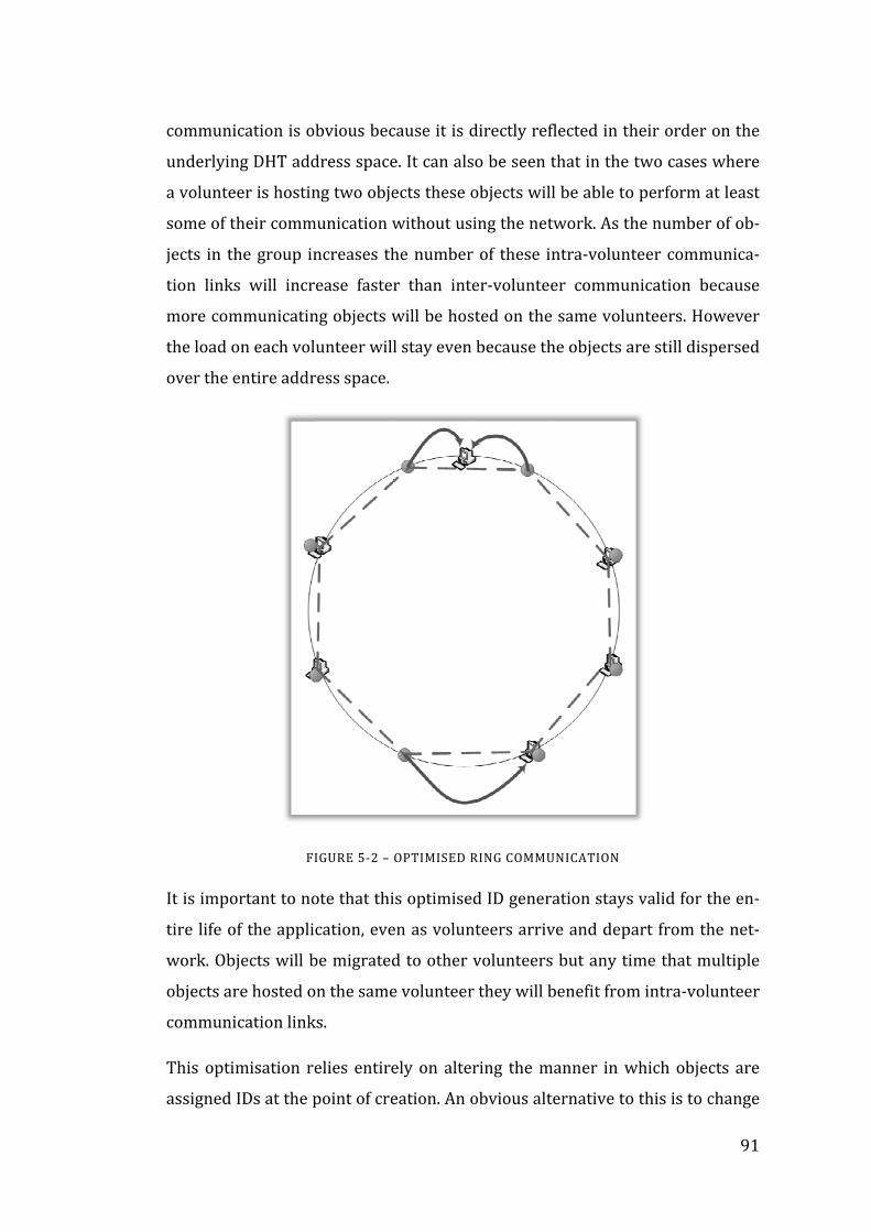
communi
underlyin
a volunte
some of t
jects in th
tion links
more com
the load o
over the e
It is impo
tire life o
work. Obj
objects ar
communi
This optim
assigned
cation is o
ng DHT add
er is hostin
heir comm
he group in
s will incr
mmunicatin
on each vol
entire addr
FI
ortant to no
f the appli
jects will b
re hosted o
cation link
misation re
IDs at the p
bvious bec
dress space
ng two obje
munication w
ncreases th
ease faster
ng objects w
unteer will
ress space.
IGURE 5‐2 –
ote that thi
cation, eve
be migrated
on the same
ks.
elies entire
point of cre
cause it is d
e. It can als
ects these o
without us
he number
r than inte
will be hos
l stay even
OPTIMISED R
is optimise
en as volun
d to other
e volunteer
ely on alte
eation. An o
directly ref
so be seen t
objects wil
ing the net
r of these i
er‐voluntee
sted on the
because th
RING COMMU
d ID gener
nteers arriv
volunteers
r they will b
ring the m
obvious alt
flected in th
that in the
l be able to
twork. As t
ntra‐volun
er commu
e same volu
he objects a
UNICATION
ration stays
ve and dep
s but any ti
benefit from
manner in w
ternative to
heir order
two cases
o perform a
he number
nteer comm
nication b
unteers. Ho
are still dis
s valid for t
part from th
ime that m
m intra‐vol
which obje
o this is to c
91
on the
where
at least
r of ob‐
munica‐
ecause
owever
persed
the en‐
he net‐
multiple
lunteer
cts are
change

92
an object’s ID during the execution of the application to take advantage of the
current communication patterns. However, updating objects’ IDs once they
have been assigned complicates G2:P2P’s communication mechanisms. Inter‐
object communication is addressed based on an object’s ID. This addressing
allows objects to be contacted even though their host volunteer may change as
volunteers come and go from the network. If an object’s ID is changed once
there are other references to that object on the network some method of redi‐
recting communication must be provided.
There are two options available for handling altered ObjectIDs:
1. Update all references to the object with the new ID, or
2. Leave a forwarding indicator at the object’s previous ID and forward
messages as they arrive.
Updating all the object references would potentially be a very expensive opera‐
tion. To do this the update message would either have to be passed to every
node in the network or a central list of all references would need to be kept.
Contacting every node in a large P2P network is prohibitively expensive and
hence not a reasonable option. Keeping reference lists would be possible but
would require close monitoring of all inter‐object messages to detect when
references are copied to other objects. Ultimately this would significantly in‐
crease the overhead of the G2:P2P communication system.
Message forwarding is a fairly simple approach and has been used in some
other distributed systems(51). However, message forwarding does require
each node to keep lists of forwarding addresses and increases the cost of com‐
munication by including more nodes in a message path. While message for‐
warding may be acceptable for small numbers of objects with limited reloca‐
tion the static method described here is significantly simpler and is suitable for
a large number of applications. Additionally, none of the optimisations de‐
scribed in this chapter preclude the future development of a dynamic reloca‐
tion system utilising message forwarding.

93
This optimisation significantly improves the locality of objects assigned to the
same volunteer but it does not address how objects that do not end up being
hosted on the same node can improve their communication performance.
However, the ObjectID ordering presented here forms the basis for further op‐
timisations presented later in this chapter which will improve inter‐volunteer
communication.
This optimised allocation scheme requires slightly more information than the
standard method. Previously the only information required to create a G2:P2P
object was the type of the object and any parameters to its constructor. To
generate a uniform distribution of ObjectIDs the ID generator needs objects to
be created as part of a group. These object groups are designated by the appli‐
cation programmer when they create the object. Initially just the size of the
group, m, is required so that the distance between each object in the address
space can be calculated by dividing the address space in m even segments.
Once the generator has this information each object in the group can be
created as usual. The generator generates a random ID for the first object then
allocates each subsequent object by adding the calculated distance to the pre‐
vious ID. This will ensure that each object in the group is evenly spaced be‐
tween its neighbours (that is, neighbours within the group not including other
non‐related objects). This generation process is handled entirely by the creat‐
ing node without the need for global coordination.
Since these object groups may coexist with other objects ObjectID clashes are
still possible for each individual object. These are handled in the usual manner
by allocating the closest available ID. The slight variation in distance caused by
these clashes will not significantly alter the locality properties.
This optimisation changes the basic manner in which application programmers
instantiate G2:P2P objects. Whereas previously they have simply used the
standard .NET “new” operator, they must now provide extra information when
objects groups which require this enhanced ObjectID assigned are created.
Whilst the current system requires application programmers to supply these

94
details manually, it is possible that some form of automated analysis, either
static or dynamic, could be used to generate these mappings. Such automated
analysis is beyond the scope of this thesis. Section 5.3 will outline how this op‐
timisation is made available to application developers.
5.2.2 Optimisation 2 – Object Collocation
The previous optimisation increases the chances that two objects that commu‐
nicate often will be located on the same volunteer, however it does not guaran‐
tee that they are always hosted together. The optimisation described in this
section is designed for situations in which a small set of objects communicate
so frequently with one another that they should always be collocated on the
same host.
Collocation is provided by adding extra bits to ObjectIDs, extending them
beyond the length of the NodeIDs. This can be thought of as turning ObjectID
into fixed point numbers rather than integers. Objects which share the same
integer part will always be mapped to the same volunteer.
Application programmers use this optimisation by indicating at instantiation
time that a group of objects should be collocated. This group of objects is then
assigned ObjectIDs with the same, randomly assigned, integer part, ensuring
they are placed on the same volunteer. The actual physical volunteer may
change over time as volunteers come and go, but the group of objects will al‐
ways be collocated. Note that this locality comes at the cost of load balance and
therefore parallelism. If a group of objects are assigned the same integer part,
they will always map to a single machine, even if there are a large number of
other nodes in the network which are completely unused. Usually, however,
these nodes will be populated by other objects used by the application or by
other applications.
An alternative method of achieving this optimisation is to encapsulate these
objects inside a single remote object container that forwards messages to them.
The advantage of the approach described above is that each of the objects in
the group remain individually addressable by remote clients. Whether or not a

95
set of objects should always be collocated is an performance optimisation
which ideally should be kept separate from the application logic and the ab‐
stractions used.
5.2.3 Optimisation 3 – Volunteer Balancing
The assignment of ObjectIDs and NodeIDs described so far will lead to approx‐
imately the same number of objects being allocated to each volunteer. In some
cases however, particularly with smaller networks, this balance may not be
reached. The third optimisation presented is used to improve load balancing,
particularly with networks with only a small number of volunteers. More im‐
portantly, this optimisation also provides a basis for the fourth optimisation
which directly addresses the physical relationship between volunteers.
The goal of this optimisation is to achieve a more uniform spread of volunteers
around the entire DHT address space. Currently volunteers are assigned ran‐
dom IDs when they join the network. While this random assignment provides a
reasonable distribution this optimisation aims to provide a much more even
spread of volunteers. Because the set of volunteers is continually changing this
optimisation is an ongoing process during the lifetime of the network.
As discussed earlier, it is extremely problematic to change an object’s ID after it
is initially assigned because references to that object may have spread
throughout the entire network. It is however possible for a volunteer’s NodeID
to change at a later time. A simple way to explain why this is possible is to view
the process as equivalent to a volunteer leaving the network and then imme‐
diately rejoining (with a new NodeID). Obviously performing a full depar‐
ture/arrival process for each NodeID change would be expensive, however
with a little ingenuity a process can be developed that is much more efficient
than the naïve implementation hinted at above.
Since G2:P2P is a decentralised system, the uniform volunteer distribution
must be obtained through a series of local operations performed by each vo‐
lunteer. From the point of view of an individual volunteer, uniform distribution
is demonstrated by being equidistant between its two immediate neighbours.

96
If each individual volunteer in the network adjusts itself so it is evenly spaced
between its neighbours then the entire network will move towards a stable
uniform distribution. The beauty of this approach is that even if new volun‐
teers join the network or old ones depart the process automatically adjusts to
incorporate these changes without any special cases. Obviously in a real net‐
work a perfect uniform distribution is unlikely to form if there are constant
changes in membership however a reasonable distribution should be quickly
obtained and still provide the improved load balancing that is being aimed for.
Since each volunteer in the network is making adjustments to its NodeID inde‐
pendently it may take a large number of small adjustments to get to a steady
state. This conversion may be sped up by making use of the extra information
each volunteer is holding in its leaf set. The leaf set allows the volunteer to
predict the changes that its neighbours will be making, most likely simulta‐
neously, to their NodeIDs. To allow for this, instead of a volunteer simply plac‐
ing itself halfway between its two immediate neighbours, it measures the dis‐
tances to all of its known neighbours and attempts to balance them. This ba‐
lancing is particularly effective if there are large gaps in the leaf set that are not
immediately adjacent to the volunteer.
The following formulas describe how volunteers calculate their incremental
NodeID changes.
2
1
,
" "
Where Wdir indicates the weight of the respective half of the leaf set and LSetdir
represents the set of volunteers in each half of the leaf set. Essentially Wclock

97
and Wanti calculate the force exerted on the volunteer by the nodes in the
clockwise and anti‐clockwise half leaf set. The term Sleafset ensures that volun‐
teers that are further away express less force than nearby volunteers. The new
position for the volunteer is calculated such that those two forces will be equa‐
lised.
A weighting factor (nweight) is also included on each volunteer. This weight al‐
lows the volunteer movement process to take into account volunteers that
have greater processing power than normal (e.g. a cluster computer rather
than a PC). Such volunteers will be responsible for a greater portion of the ad‐
dress space and hence will automatically be assigned more objects.
Since it is imperative that the relative order of the volunteers is maintained,
volunteer movement is further restricted so that any single move may not tra‐
vel more than half the distance to the next volunteer. Without this restriction
volunteers may “cross over” each other as they independently calculate their
moves. This restriction may slow down the progress towards the global optima,
however, once the network is well dispersed volunteer movements are gener‐
ally small anyway and this restriction is rarely encountered.
Now that it has been established that moving NodeIDs is a beneficial operation,
it is worth looking at a method of moving IDs which is more efficient than the
naive disconnect/reconnect approach described earlier in this section. It is es‐
sential that any enhanced moving scheme does not corrupt the routing infor‐
mation that each node maintains. In section 2.1.3 three categories of routing
information that is used by the Pastry network were described – the neigh‐
bourhood set, leaf set and routing table.
The neighbourhood set is not used directly in routing, rather it is used to pro‐
vide physical locality information and therefore cannot be corrupted by
changes in the virtual address of a node.
The leaf set holds the addresses of nodes whose NodeIDs are closest to the leaf
set’s owner. The leaf set is essential to the Pastry routing system. Provided the
leaf sets of all volunteers on the system stay valid then routing is guaranteed to

98
complete correctly. For this reason a volunteer keeps in regular contact with
its leaf set which means that any changes to a volunteer’s ID can be quickly
communicated to its leaf set. The one potential problem with moving a volun‐
teer’s ID is that it may change order of volunteers in the address space. If this
happens then the leaf set will become invalid and routing may be corrupted.
The volunteer balancing mechanism must therefore include safeguards to en‐
sure that volunteers do not move their IDs past either of their immediate
neighbours.
The routing table maintains links to various volunteers across the system and
is the primary routing mechanism in Pastry. Unlike the leaf set, a volunteer
does not know which routing tables it is part of and therefore can’t inform
them of any changes to its NodeID. While this would appear to be a significant
problem, when the role of the routing table is examined it is apparent that in
most cases changing NodeIDs will not cause ruinous problems. The routing ta‐
ble is used to quickly communicate a message to the general area of its target
node. Since it is expected that most changes to a NodeID should be relatively
small, at least once a network is up and established, even when a routing table
entry is selected for hopping a message the small differences in NodeID will
not alter the overall effect of the message hop. That is, the message will still be
significantly closer to its target than it previously was. Even in the worst case
when a NodeID has changed significantly, routing will not be broken by deli‐
vering to an incorrect entry in the routing table. The message may simply pass
through more intermediate nodes than it would do so ideally.
To maintain the routing state in the long term nodes should be informed if they
have an incorrect entry. Incorrect entries can be detected by simply including
the NodeID each individual hop was sent to as part of the hop. When a volun‐
teer receives a message and detects that it was sent to the wrong ID because of
a change in NodeID the volunteer reply to the previous node, providing it with
a new NodeID so it can update its state appropriately. The handling of the ac‐
tual message will continue normally.

99
So it can be seen that provided the volunteer movement mechanism maintains
the relative order of volunteers there is no need to disconnect and reconnect
the volunteers. When a volunteer changes its ID it simply needs to inform its
leaf set of the change. It also needs to monitor incoming messages to detect if
other volunteers have outdated information. When such inconsistencies are
discovered the volunteer simply sends updated details to the other node.
The volunteer’s routing state must also be updated to reflect the new NodeID.
The leaf set is not affected because the volunteers with adjacent NodeIDs are
guaranteed not to change. Similarly, the neighbourhood set is unchanged since
it is only related to physical locality, not the NodeID. The amount of the routing
table affected is directly related to the distance moved by the node. Generally
the top rows of the routing table will stay constant, while bottom rows will
need to be repopulated. Repopulation of these rows can generally be done by
obtaining leaf set members’ routing tables during standard heartbeat messages
without much extra overhead.
Since each NodeID movement requires a certain amount of overhead in com‐
municating the change to its leaf set, and may trigger other costly events such
as object migrations, there should be some attempt to limit the frequency of
these movements. At some point the benefit to load balancing gained from a
movement is outweighed by the cost of performing the movement. Each node
movement incurs a cost in communicating the new ID to its neighbour, but
more importantly, each movement may result in the migration of objects be‐
tween volunteers. These object migrations can be relatively expensive and
hence should be avoided if the gain is not significant. This cost is difficult to
quantify at the volunteer level since it requires global knowledge of the net‐
work layout and load, but it highlights the need to place a minimum threshold
for any single NodeID movement. If, once an ID movement is calculated, it is
found to be under this threshold the calculation is simply discarded and no
movement occurs.
The threshold used depends on the number of volunteers in the network and
the size of the address space. As the number of volunteers in the network in‐

100
creases there should be less gap between volunteers and so smaller move‐
ments become more important. Conversely, the larger the address space the
larger the gap between nodes and hence small movements become less impor‐
tant. The size of the address space is directly related to the length of the Node‐
IDs. The threshold, T, can be derived from these two relationships:
1
The constant c is a configuration value which represents the sensitivity of the
volunteer balancing mechanism. This sensitivity controls how quickly the vo‐
lunteers move to their optimum position. It is analogous to the Gain Factor in a
control system using proportional control. If the sensitivity is set too low the
volunteers will take a long time to reach their balanced position. While a high
sensitivity will cause the volunteers to quickly respond to changes in their bal‐
ance, but may cause them to never reach a steady state since even small
changes in their neighbours will cause movement. These two processes are
well understood in control theory and are referred to as overdamping and un
derdamping.
When calculating this threshold the limitation of no global knowledge is en‐
countered once again. A single node cannot know the current number of nodes
involved in a network. It can however approximate this value by examining
how much of the address space its leaf set is occupying and extrapolate to find
the total network size. This approximation actually becomes quite accurate as
the network is balanced via the volunteer balancing process.
Optimised Joining ID
When a node joins there is a significant opportunity to optimise its location be‐
fore it even advertises itself to other nodes. The standard Pastry join procedure
uses a randomly generated NodeID. This random NodeID helps to distribute
the nodes across the NodeID address space. However, with the addition of the

101
volunteer balancing scheme described above this random distribution is less
important. If a node could be placed equidistant between two neighbours in‐
stead of simply randomly assigned an ID then the network would already be
partially balanced and there would be less movement steps required to stabi‐
lise the network. Since each movement step requires extra communication
amongst the leaf set any reduction in movement results in less communication
overhead.
The standard Pastry join procedure starts with the new node routing a special
join message to its randomly generated NodeID. This join message is received
by the node whose ID is closest to the new position who then replies with con‐
firmation of the IDs acceptance and with some initial data to start populating
the node’s routing state. This join message can be used to detect NodeID con‐
flicts. If a node receives a join message for its own NodeID it simply replies
with a message indicating the NodeID is unavailable and the joining node se‐
lects a new ID to join with.
For the enhanced joining process the node needs to find two nodes which it
will position itself between then calculate their midpoint and select that as its
NodeID. Since there is no central body which can perform the calculation the
node must somehow select its own prospective neighbours. The existing join‐
ing process provides an effective method of doing this and allows the enhanced
process to be implemented with few changes.
The joining node generates a random NodeID as per usual and routes a join
message to that ID. When that join message is received it is processed slightly
differently. Instead of simply checking that the ID is valid and does not conflict
with existing IDs, the node now uses its leaf set to establish the new node’s
neighbours. The node then calculates the balanced position for the new node,
exactly as it would during a NodeID movement calculation. The node has suffi‐
cient information for this calculation because the new node’s leaf set will con‐
sist of the calculating node along with a subset of its own leaf set.

102
Once the balanced NodeID has been calculated the ID is returned in the join
message’s reply. When the joining node receives this reply it continues its join‐
ing process in the same manner it normally would, but with the new NodeID
returned from the join message.
In the enhanced scheme described so far the initial random NodeID is used to
select the neighbours of the joining node. However, this ID is simply used to
find the initial target of the join message. There is no reason why this join mes‐
sage can’t be redirected to a another position that offers a better balancing
prospect for the network if one can be found. The actual suitability of the ran‐
domly selected position is not known until the join message is received by its
target node. However, at that point the node can examine its leaf set and search
for better positions. The best position for a node to fill is the largest gap in the
address space between two nodes. While the receiving node does not know the
global best position, it can easily select the largest gap within its leaf set. Once
this is found it simply redirects the join message to the new position. The new
target node does not need to know that the join message had been redirected
and can perform the entire process again.
This redirection does however need to be limited somewhat. It is possible that
a join message may be redirected repeatedly, passing it gradually around the
node address space. In fact, because of the dynamic nature of the network –
there are regular node arrivals and departures and node’s IDs are being moved
– it is possible that the join message will never be actually processed. To pre‐
vent this a join message needs to keep a count of how many times it has been
redirected and redirection ceased after a certain threshold. It is not a signifi‐
cant issue if this threshold is reached as the goal of this enhancement is to
simply improve the initial joining position, not to select the absolute optimum.
5.2.4 Optimisation 4 – Node Ordering
The optimisation in section 5.2.1 describes how an alternate ObjectID assign‐
ment method can increase the chance that two objects that communicate often
will be located on the same machine. There are however usually situations

103
where objects that communicate often are located on different machines. If
these objects cannot be on the same machine (and indeed the entire goal of
G2:P2P is to distribute objects amongst multiple machines to benefit from ad‐
ditional computing power) then it is preferable that they are hosted on ma‐
chines that are physically close. This section describes a change to the layout of
Pastry nodes which allows physical locality to be reflected in the virtual Pastry
address space. By connecting the volunteer’s NodeIDs to their physical location
the uniform ObjectID distribution described in section 5.2.1 will benefit from
improved inter‐node communication along with the intra‐node communication
it already achieved.
Essentially what the optimisation proposes is to assign NodeIDs based on some
information which reflects the volunteer’s physical locality. For example, by
comparing two volunteer’s IP addresses some insight can be gained as to their
position within a network. Nodes with similar IP addresses, especially identical
subnets, presumably have good communication links, while totally unrelated
addresses are similarly unrelated in their communication links. Therefore, if
volunteers with similar IP addresses are assigned similar NodeIDs, the speed
of volunteers’ communication links will be reflected by the proximity of their
NodeIDs. Once a link is formed between NodeIDs and their physical proximity,
the previous ObjectID ordering optimisation can be used to place objects which
regularly communicate on physically close volunteers.
IP addresses can be converted to NodeIDs using any simple mapping function.
For example, if the NodeID is the same length (i.e. has the same number of bits)
as the IP address then a simple identity function will suffice. Otherwise some
form of truncation or zero‐padding can be used to adjust the IP address to the
correct size. In the case of truncation the standard G2:P2P joining procedure
will correctly handle NodeID clashes. The only important property of the map‐
ping function is that it must maintain the relative order of the IDs. That is, No‐
deIDs generated from IP addresses must be in the same order as their original
IP addresses were.

104
When volunteers are assigned IDs randomly, they are naturally distributed
across the entire address space. By tying the volunteers’ IDs to their IP address
this natural distribution will no longer occur and a severely unbalanced net‐
work could easily form. For this reason this optimisation must always be com‐
bined with the previous volunteer balancing optimisation. The volunteer ba‐
lancing process will overcome any imbalance caused by the systematic genera‐
tion of NodeIDs.
However, using the volunteer balancing technique complicates the joining
process. As volunteers adjust their IDs, they may find themselves moving sig‐
nificantly away from the ID that was generated based on their IP address.
While this is not a problem during the standard operation of the network, it
does present an issue when volunteers join. As usual, volunteers will send a
join message to their prospective NodeID (that is the ID generated from their
IP address). Without the volunteer balancing in effect that prospective NodeID
will place them amongst physically related volunteers. However, if those re‐
lated volunteers have moved since they joined, the generated ID and its
neighbours may have no physical relationship. This issue is entirely restricted
to join messages and hence does not require substantial changes to resolve.
The issue fundamentally comes down to the disconnect between a nodes cur‐
rent ID and its original ID. While normal communication messages use the cur‐
rent NodeID, the join messages need to be routed based on nodes’ original IDs.
Unfortunately the routing table maintained by each node is designed for stan‐
dard routing and hence can not be used for routing based on original IDs.
However, due to the properties of the volunteer balancing technique, the order
of current IDs will be identical to their original ID order. This means leaf sets
can be used to route messages, albeit with a worse case of N/2 network hops.
In practice, joining is generally performed by contacting a physically close node
and using it to initiate the join message. This means that regardless of how far
volunteers’ IDs move during execution, join messages will always be initiated
reasonably close to their final target.

105
There is one disadvantage of applying this optimisation. In a normal Pastry
network, nodes in a particular physical locality are likely to be widely spread
throughout the network’s address space. This means that if some fault in that
physical locality occurs (such as a local power loss or a local network issue)
then loss of nodes will be felt in a dispersed fashion across the network rather
than in a single large cluster. Pastry networks are designed to be able to recov‐
er from individual nodes disappearing unexpectedly, provided that other
nodes in the leaf set remain. So by changing this aspect of the pastry network
its ability to recover from local faults is decreased. This is obviously a trade‐off
that must be made between efficiency and reliability.
While this trade‐off may not be suitable for ad‐hoc networks hosted on the In‐
ternet, it would be of considerable use for networks spread across a number of
reliable sites with good interconnections. Each site’s nodes would be posi‐
tioned next to each other within the virtual address space and hence would
benefit from high speed communication links. These communication links
would be utilised by communicating objects, especially when combined with
the first optimisation presented in this chapter, but would also benefit the
standard upkeep of the network since most network overhead is performed
amongst leaf set nodes. Longer range routing would also benefit as a message
originating on one side of the network would very quickly arrive at the physi‐
cal destination site due to Pastry’s log(N) routing scheme and then efficiently
redirect to its ultimate target on the high speed internal network.
5.3 Programming Model Extensions
While most of the optimisations presented in this chapter require no special
effort by application developers, the first two optimisations – ObjectID order‐
ing and object collocation – do require some extra information to be provided.
In both cases the new features work with groups of objects. The improved ob‐
ject spacing takes a group of objects and assigns their IDs systematically to im‐
prove their locality. Similarly, the object collocation also takes a group of ob‐
jects, but instead ensures they are located on the same processing node. This

106
similarity allows us to provide a consistent programming interface for both op‐
timisations.
It is important that these optimisations do not limit how objects are created.
For instance, it would be possible to provide an API call which took a type pa‐
rameter and a parameter indicating the number of objects to create. The call
would simply create the indicated number of objects of the specified type as a
group, either uniformly dispersing the group as the first optimisation describes
or collocating them according to the second optimisation. However, this inter‐
face would only allow groups to contain a single object type and also does not
allow for parameters to be passed to the object constructors.
Arguably the simplest interface for creating object groups would be to provide
a method which takes an array of objects and groups them for spacing or collo‐
cation. Unfortunately, such an interface is impossible to implement. Any im‐
plementation of this method would require objects’ IDs to be altered to per‐
form the spacing or collocation. Changing ObjectIDs like this is impossible, as
was discussed earlier, making any post‐creation grouping of objects unattaina‐
ble.
It is the therefore necessary to ensure object groups are created at, or before,
creating the objects. To allow the maximum amount of flexibility it is important
that objects can be created using the standard “new” operator. Since the “new”
operator cannot easily be extended in .NET, the size of the group must be
communicated to the ObjectID generator prior to creating the objects. A simple
method call can supply the group size, n, to the generator before any objects in
the group are created. Once this call is made the generator is placed in a special
mode where it will generate the appropriate ObjectIDs (either spacing them or
collocating them) for the next n objects.
Listing 5‐1 demonstrates how the object spacing optimisation is used. This
sample generates a set of “Island” objects which are evenly spaced around the
network. In this case all of the objects are of the same type (Island) but each
object takes a different integer parameter which is used for identification.

107
Island[] islands = new Island[numIslands]; G2P2PChannel.Current.StartSpacingObjects(numIslands); for (int i = 0; i < numIslands; i++) islands[i] = new Island(i);
LISTING 5‐1 – USING THE OBJECT SPACING OPTIMISATION
Listing 5‐2 demonstrates how collocation is used. As expected the interface is
very similar to the object spacing interface. In this sample a group of 3 related
objects are collocated for improved communication. The group of objects that
are collocated consist of three different types, ClassA, ClassB and ClassC, and
take entirely different parameter lists. It is important to note that G2:P2P only
intercepts the “new” operator for G2:P2P objects, not standard .NET objects.
The only change from the original, unoptimised code is the addition of the
StartCollocatingObjects call. This is important as it allows the application de‐
veloper to take advantage of collocating objects without compromising the de‐
composition of their solution.
Once StartCollocatingObjects is called the next n objects on that thread are al‐
located using the collocation optimisation; this decision is made at runtime. An
alternative method, using a pair of StartCollocating/EndCollocating methods
could have been provided, but the single call was chosen instead to keep the
interface consistent with the object spacing optimisation. There is no technical
reason why a Start/End pair could not also be provided.
G2P2PChannel.Current.StartCollocatingObjects(3); ClassA a = new ClassA(new int[] {2, 3, 4}); ClassB b = new ClassB(a); ClassC c = new ClassC(b, c);
LISTING 5‐2 – USING THE OBJECT COLLOCATION OPTIMISATION
In summary, there are three distinct methods of allocating ObjectIDs in G2:P2P.
1. The original, random ID generation which provides load balancing by
distributing the objects around the entire address space. This is the de‐
fault allocation scheme in G2:P2P.

108
2. The object spacing optimisation which takes a group of objects and
evenly spaces them around the address space. This is activated through
a call to G2P2PChannel.Current.StartSpacingObjects as shown in Listing
5‐1.
3. The object collocation optimisation which takes a group of objects and
ensures they are hosted on the same volunteer machine. This is acti‐
vated through a call to G2P2PChannel.Current.StartCollocatingObjects as
shown in Listing 5‐2.
These additions to the programming model place some small burden on the
application programmer. These burdens are as small as possible – simply pro‐
viding the necessary information to the system for it to enact the optimisations.
The programmer is still free to employ their usual techniques for creating and
using objects. It is possible, though unlikely, that the number of objects being
created is not easily known when the calls to StartSpacingObjects or StartCol‐
locatingObjects must be made. If this was the case an alternative procedure
which marked the start and end of when the optimisations were to be applied
would be useful. This would be simple in the case of StartCollocatingObjects
but would be extremely difficult to implement in the StartSpacingObjects case.
For this reason the described method was chosen, keeping a common pattern
to both calls.
5.4 Conclusion
In this chapter I have presented four methods of optimising the performance of
applications running on a fully decentralised cycle stealing framework. These
optimisations are particularly useful to applications with inter‐object commu‐
nication, but also provide benefits for non‐communicating applications.
The first two optimisations use the concept of object locality, familiar from
other high‐performance computing endeavours, to improve inter‐object com‐
munication performance by systematically assigning their ObjectIDs. These op‐
timisations improve performance by increasing the probability that regularly
communicating objects are hosted on the same volunteer.

109
The final two optimisations alter the underlying decentralised network layer.
These optimisations adjust the layout of the volunteers in the virtual P2P ad‐
dress space to improve locality of objects hosted on different volunteers. These
optimisations build on the previous two to further improve communication
performance. Since these optimisations are implemented at the P2P layer they
are not coupled to cycle stealing and could be used by other fully decentralised
networks.

110
6 Evaluation
A prototype implementation of G2:P2P has been developed in C#. Although
this prototype has not been optimised for maximum performance, it provides a
reasonable test bed for evaluating the design of G2:P2P. Like G2:P2P, the pro‐
totype has been developed from scratch without any input from G2:Classic.
The entire prototype consists of 19 500 lines of code including tests. Sections
of the prototype are also of interest as separate modules. In particular the
TcpEx module – a bidirectional TCP channel for .NET ‐ has been released publi‐
cally under a BSD license.
Three test applications have been developed using this prototype. These ap‐
plications were then used to test the performance of the system on a typical
university computing lab. The third application was developed by Johan
Berntsson as part of research into distributed evolutionary computing(52) but
was not used during performance testing. These three applications demon‐
strate how G2:P2P handles a variety of different parallel application styles.
The prototype includes a complete implementation of the G2:P2P system as
described in Chapter 3 and the fault tolerance extensions described in Chapter
4. Additionally two of the four optimizations described in Chapter 5 – Objected
ordering and volunteer balancing – have been implemented and their effect
measured.
In this chapter I will evaluate the G2:P2P framework. Section 6.1 presents the
test applications. Section 6.2 evaluates the performance of the prototype
G2:P2P system and will include examining the effectiveness of the optimisa‐
tions presented in chapter 5. Section 6.3 evaluates the overhead of the fault to‐
lerance system presented in Chapter 4.
6.1 Test Applications
The first application is an embarrassingly parallel application for calculating
the Mandelbrot set. Embarrassingly parallel applications are common candi‐

111
dates for cycle stealing systems because they do not require inter‐task com‐
munication. As a test application it provides a basic example useful for measur‐
ing raw performance.
The second, more sophisticated application uses a lattice gas model to simulate
surface tension between two fluids. The application uses a cellular automaton
to run the simulation. Cellular automata use a considerable amount of struc‐
tured inter‐object communication. This test demonstrates how G2:P2P can be
used to address problems that were essentially impossible to approach with
traditional cycle stealing systems. The communication style is also similar to
other parallel applications such as finite element simulations which typically
are run on multi‐core or cluster machines. In addition, the cellular automata
provides a test bed for evaluating the efficacy of the locality optimisations in‐
troduced in Chapter 5.
G2:P2P was also used by Johan Berntsson to develop a cycle‐stealing genetic
algorithm framework called G2DGA (52). The library uses the parallel form of
genetic algorithm called the island model. While the island model can be cor‐
rectly implemented in an embarrassingly parallel form, the distributed object
form used by G2:P2P more closely reflects the structure of the island model.
G2DGA has not been used to gather performance data since it was developed
with an early version of G2:P2P, however its basic structure still conforms with
G2:P2P.
The following sections will examine the two test applications in detail.
6.1.1 Mandelbrot – Embarrassingly Parallel
The majority of existing cycle‐stealing applications are embarrassingly parallel.
Embarrassingly parallel problems are well suited to cycle‐stealing because the
only communication link required is between the task and the client (or the
broker if it is collecting results on the client’s behalf). Additionally, embarras‐
singly parallel designs do not require complex fault tolerance mechanisms. If
an error occurs with a single task the task can simply be restarted without af‐
fecting any other part of the application. Although embarrassingly parallel ap‐

proach
cludes
astrop
This t
the ca
plex n
region
ing wh
not. Th
the m
Figure
This te
but do
6.1.2
Cellula
own st
hes are on
s some
physics(53)
est applica
lculation o
number pla
n is assigne
hich portio
he results
anner typi
e 6‐1.
est applica
oes not mak
Lattice Ga
ar automat
tate(55). C
nly suitable
significan
).
ation uses
f the Mand
ane and di
d to a sepa
ns of that r
of this calc
ically used
tion uses t
ke use of in
FIGURE
as Simulat
ta are discr
ells change
e for some
t membe
an embarr
delbrot set.
issects it in
arate G2:P2
region are
culation ar
to visuali
the basic re
nter‐object
6‐1 – MAND
tion – Cellu
rete model
e states acc
e problems
ers inclu
rassingly p
The algori
nto a num
2P object w
part of the
re returned
se the Man
emote obje
communic
ELBROT VISU
ular Autom
ls consistin
cording to a
s, this set o
ding pro
arallel algo
ithm takes
mber of sub
which is resp
e Mandelbr
d to the clie
ndelbrot se
ct features
cation.
UALISATION
maton
ng of a set o
a set of rul
of problem
otein fold
orithm to p
a region o
b‐regions.
ponsible fo
rot set and
ent and dis
et (54) as
s supplied b
of cells eac
es which a
112
ms still in‐
ding and
parallelise
f the com‐
Each sub‐
or calculat‐
which are
splayed in
shown in
by G2:P2P
ch with its
re applied

in discret
areas incl
Lattice ga
of fluids a
lattice ga
allow mo
keep trac
teraction
applicatio
(see Figur
Cellular a
every cell
calculatio
immediat
in paralle
ue to its n
calculatio
kept cellu
te time ste
luding phys
as automat
at the part
as models a
re particles
ck of a num
potentials,
on is a sim
re 6‐2).
FIGURE 6
automata a
l in the au
on only req
te neighbou
el. Between
neighbours
on. Howeve
ular autom
eps. Cellula
sics, biolog
ta(56) are
ticle level.
allow strai
s to be sim
mber of con
, for each p
mulation of
6‐2 – LATTICE
are good c
utomaton is
quires the
urs. This m
n each time
s so they h
er, this req
mata out of
ar automat
gy and artifi
cellular au
Because ce
ightforwar
mulated than
tinuous va
particle. Th
f the intera
E GAS SIMUL
andidates
s inspected
cell’s curre
means that
step a cell
have suffici
uires frequ
f the reach
ta can be u
ficial life.
utomata use
ellular auto
d impleme
n finite ele
alues, such
he specific
action betw
LATION OF IM
for paralle
d and its n
ent state a
each cell c
l simply ne
ent inform
uent, direct
h of centra
used to m
ed to mode
omata are
entation on
ment mode
as position
problem so
ween two i
MMISCIBLE F
elisation. A
ew state is
and possibl
an potentia
eeds to com
mation to pe
t communi
alised cycle
odel a var
el the inter
entirely di
n compute
els which h
n, velocity a
olved by th
immiscible
LUIDS
At each tim
s calculated
ly the state
ally be pro
mmunicate
erform the
ication whi
e stealing
113
riety of
raction
iscrete,
rs and
have to
and in‐
his test
e fluids
me step
d. This
e of its
ocessed
its val‐
eir next
ich has
frame‐

114
works. Since G2:P2P provides direct inter‐volunteer communication a cycle
stealing implementation of cellular automata can now be realised.
Since the calculations required for each cell are typically very quick parallelis‐
ing at the cell level is too fine grained for cycle‐stealing. Instead, this test appli‐
cation splits the cells in to a finite set of groups. Each of these groups is as‐
signed to a separate G2:P2P object which will handle the calculation of all cells
in the group. This limits the amount of data that needs to be communicated be‐
tween objects to the states of the just the edge cells.
The test application has further reduced inter‐object communication by not
exchanging data on every time step. Each object calculates a number of steps
and then exchanges the data. This results in some replication of calculations
because there is a common area on each group’s border which must be calcu‐
lated by multiple objects. However, the decreases in the frequency that data
needs to be communicated more than compensates for this extra processing.
6.2 Speedup Tests
Two typical university computing laboratories were used to evaluate the per‐
formance of G2:P2P. The two labs consisted of a total of 56 desktop machines –
26 Core Duo 3GHz machines and 30 Pentium 4 3GHz machines connected by a
100Mbps Fast Ethernet network.
The two test applications described in Section 6.1 were run on this network.
The Mandelbrot test was run on an area of the complex plane between [‐2‐2j]
and [2+2j] at a resolution of 0.0001 units in both dimensions. The lattice gas
simulation was run on a 1600×1600 cellular automata for 50 steps. The objects
exchanged data on every fifth step. Both applications used 144 objects (a
12x12 grid).
Two optimisations have been implemented and tested within the prototype
G2:P2P system – the ObjectID ordering optimisation presented in Section 5.2.1
and the volunteer balancing optimisation presented in Section 5.2.3.

The first
patterns,
uses a lot
should ex
Figure 6‐3
automata
benefit w
FIGU
These res
machines
sons for t
The test n
chines we
lel. Howev
machines
nature of
optimisati
was tested
t of inter‐o
xpect consid
3 shows th
a. It shows
with networ
RE 6‐3 – SPE
sults show
s, however
hese result
network co
ere dual co
ver, the rem
s did have
f the applic
ion, orderin
d with the
object comm
derable ben
he effect of
that the o
rks of all siz
EEDUP OF OB
w that the s
this speedu
ts.
onsisted of
re machine
maining 30
hyper‐thr
cation prev
ng ObjectID
e cellular a
munication
nefits from
optimising
optimised f
zes.
JECT ORDER
system pro
up is less th
two sets o
es capable
0 machines
readed pro
vented hyp
Ds accordi
utomata a
n in a near
m this optim
g the order
form gains
ING OPTIMIS
ovides spee
han linear.
f disparate
of executin
had only a
ocessors, th
per‐threadi
ing to their
pplication.
rest neighb
misation.
of ObjectID
s a reasona
SED CELLULA
edup over
There are
e machines
ng multiple
a single cor
he comput
ing from p
r commun
This appl
bour patter
Ds on the c
able perfor
AR AUTOMAT
the entire
two prima
. The first 2
e objects in
re. While th
tationally i
roviding a
115
ication
ication
rn so it
cellular
rmance
TA
e set of
ary rea‐
26 ma‐
n paral‐
hese 30
intense
ny sig‐

116
nificant benefit. This disparity is apparent in the results between the 20 and 30
volunteers. By the 30 volunteer mark the slower single core machines had
started to be included in the network. These single core machines act as a bot‐
tleneck on the application reducing its overall performance.
The second issue affecting these results is the load balance of the system.
G2:P2P relies on the random generation of IDs for both volunteers and objects
to provide load balancing. However, on the small networks used in this test
there are insufficient volunteers to provide a good random distribution across
the entire address space. This load balancing is addressed by the volunteer ba‐
lancing optimisation which was also implemented in the prototype.
This volunteer balancing optimisation was tested with both the Mandelbrot
and cellular automata applications. Figure 6‐4 and Figure 6‐5 show the
speedup when using the volunteer balancing optimisation compared to an un‐
optimised test run. This optimisation provides considerable benefits for both
applications. This benefit is primarily due to the improved load balancing that
the optimisation provides. By spreading the nodes evenly around the address
space it has ensured that each node services approximately the same number
of objects. In the unoptimised tests the load balancing can be quite uneven re‐
sulting in the application’s results relying on the completion of one particular
volunteer.

FFIGURE 6‐4 – SPEEDUP OFF MANDELBRROT WITH VOOLUNTEER BA
ALANCING
117

F
With
speedu
moves
IGURE 6‐5 –
this optim
up line. Th
s below lin
Sd
SPEEDUP OF
misation ap
his reflects
near speed
0
5
10
15
20
25
30
35
0
Speedu
p
F CELLULAR A
pplied the
s the use o
dup again w
10
Num
AUTOMATA W
results sh
of the dual
when the
20
mber of Volun
WITH VOLUN
ow speedu
l core mac
30 volunte
NOptim
Optim
30
teers
NTEER BALAN
up above t
chines. The
eer mark i
ot mised
mised
40
118
NCING
the linear
e speedup
is reached

119
since these volunteers include single core processors and act as a bottleneck to
the system.
This bottleneck could be reduced by using the number of cores in the machine
as a parameter to the volunteer balancing formula presented in section 5.2.3.
This formula already supports a weight factor for each node. If this weight is
used to reflect the overall processing power of the node, including the number
of cores, it would automatically assign dual core machines more of the object
address space and hence assign them more objects to process.
Although the tests have only been performed on relatively small networks, sca‐
lability to 56 nodes is a good demonstration for G2:P2P. The structure of the
Pastry network that G2:P2P uses changes significantly as the network grows
larger than its leaf set. At 56 nodes the network will have achieved the same
structure it uses for any larger sizes.
6.2.1 MultiCore Speedup
G2:P2P also offers benefits when run on a single machine with multiple pro‐
cessors or multi‐core processors. Each G2:P2P object is run on its own thread.
On multi‐processor machines this means that multiple objects can be executed
in parallel. Application developers can take advantage of these processors by
using the G2:P2P programming model and running a volunteer on the same
machine as the actual application. Volunteers can be run in either a separate
process or hosted within the main application process.
Both test applications were run on a dual core machine with significant per‐
formance benefits. Figures Figure 6‐6 and Figure 6‐7 show the improvements
provided by running the Mandelbrot and cellular automata on a dual core ma‐
chine. In both cases G2:P2P almost halved the running time.

6.3 F
The m
its pot
FIGURE
FIGURE 6‐7
Fault To
main issue r
tential ove
Time (m
s)Time (m
s)
E 6‐6 – SPEED
7 – SPEEDUP
olerance
raised by th
erhead. Thi
0
100
200
300
400
500
600
0
200
400
600
800
1000
1200
1400
1600
DUP OF MAN
OF CELLULA
e Overh
he fault tol
is overhead
Sequential
Sequentia
NDELBROT ON
AR AUTOMAT
head
lerance sch
d has been
l
N DUAL‐CORE
TA ON DUAL‐
heme prese
n measured
Parallel
Parallel
E MACHINE
CORE MACHI
ented in Ch
d through t
120
INE
hapter 4 is
the proto‐

type impl
thod calls
the cellul
These me
ther proc
message t
Figure 6‐
on a G2:P
pected, th
overhead
FI
Like the r
fited from
mising th
its entire
lementatio
s the cellula
lar automa
essages act
cessing unt
transmissio
8 provides
P2P networ
he fault to
d the system
IGURE 6‐8 ‐ F
rest of the p
m any optim
he scheme.
data store
0
5
10
15
20
25
30
35
Speedu
p
on. Since th
ar automat
ata frequen
t as a synch
til they are
on could re
s the speed
rk with var
lerance sy
m still gains
FAULT TOLER
prototype s
misation w
In particu
e when it re
0
5
0
5
0
5
0
5
0
he system
ta applicati
ntly exchan
hronisation
e received.
esult in sign
dup values
rying fault
stem incur
s significan
RANCE OVER
system, the
work. There
lar the loca
eceives eac
10
Number
only introd
on was use
nge messa
n point in t
For this re
nificant per
when runn
tolerance
rs a slight
t speedup.
RHEAD FOR C
e fault toler
e is conside
al storage
ch message
20
of Volunteer
duces over
ed for testin
ages with t
the applica
eason, any
rformance
ning the ce
levels. It s
overhead,
CELLULAR AU
rance sche
erable opp
scheme cu
e. This was
No FaultToleranc
LocalRemote
30
s
rhead durin
ng. The obj
their neigh
ation, haltin
overhead
costs.
ellular auto
hows that,
but despit
UTOMATON
me has not
ortunity fo
urrently ser
s done to si
t ce
40
121
ng me‐
jects in
hbours.
ng fur‐
on the
omaton
, as ex‐
te that
t bene‐
or opti‐
rialises
implify

122
the implementation but could be improved to simply serialising the latest mes‐
sage which would significantly increase its performance.

123
7 Conclusions
This thesis demonstrates how a fully decentralised network model can offer a
number of benefits to cycle stealing. I have designed a scalable cycle stealing
framework using a fully decentralised network model. Previous cycle stealing
frameworks have used predominantly centralised network models. This cen‐
tralisation has placed significant limits on the frameworks, particularly in the
areas of scalability and inter‐volunteer communication. G2:P2P demonstrates
how a fully decentralised network can provide the basis for a cycle stealing
framework which naturally overcomes these limitations.
Chapter 3 described the design of G2:P2P. G2:P2P improves on existing cycle
stealing work by providing direct inter‐volunteer communication and by pro‐
viding scalability through its underlying network model. Since previous cycle
stealing work has not provided general purpose communication facilities, a
new programming model was required for G2:P2P. A distributed object based
model is presented which integrates with the .NET Remoting framework. This
allows non‐expert programmers to approach parallel, distributed computing
using a familiar programming model.
The direct communication provided by the decentralised model allows a wider
scope of applications to be developed when compared with centralised cycle‐
stealing frameworks. This has been demonstrated with the development of a
parallel genetic algorithm framework and a parallel cellular automata applica‐
tion. Whilst genetic algorithms have been performed with centralised methods,
the decentralised version allows for a more natural implementation of the isl‐
and model. Cellular automata have not been attempted on a cycle stealing sys‐
tem because of the large amount of communication required. The prototype
implementation of G2:P2P has proven effective at providing speedup for this
application
Chapter 4 addresses fault tolerance in G2:P2P. Stringent fault tolerance on de‐
centralised networks has not been required by previous decentralised applica‐

124
tions. For cycle stealing it is an essential aspect. I have developed a reliable
fault tolerance system which takes into account the restrictions of decentrali‐
sation. Since decentralised networks do not provide any reliable storage me‐
chanism, data must be stored by replicating it across multiple nodes. My fault
tolerance system is designed to minimise the amount of data that requires rep‐
lication while still ensuring recovery is possible.
Chapter 5 presents four optimisations for improving application performance
in G2:P2P. Two optimisations are specific to cycle stealing and concentrate on
altering object locality to improve communication performance. The other two
optimisations work at the underlying P2P layer to improve the layout of volun‐
teers in the virtual P2P address space. These optimisations have been imple‐
mented and provided significant performance benefits to applications running
on G2:P2P.
The aim of this research was to investigate how a fully decentralised network
model could be used to improve cycle stealing. A prototype system, G2:P2P,
was designed and developed which verifies that decentralised cycle stealing is
possible and yields benefits. This system extends the current cycle stealing
possibilities by providing direct inter‐object communication and by using an
underlying network model which naturally scales. I have addressed fault toler‐
ance on the network, which is essential for any cycle stealing framework, and
have introduced a number of optimisation techniques which significantly im‐
prove application performance.
7.1 Future Work
The performance testing of G2:P2P suggests that load balancing is currently
causing the largest performance degradation. While the volunteer balancing
optimisation presented in section 5.2.3 improves load balancing considerably,
there are other opportunities for overcoming this issue. There are a number of
potential methods of addressing this issue. The Javelin project uses a “work
stealing” process to improve load balancing. Although this concept does not

125
directly map to the distributed object programming model presented by
G2:P2P it could be adapted to some form of “object stealing” process.
While the distributed object programming model provided by G2:P2P is neces‐
sary for supporting its communication facilities, it does not support direct
porting of existing cycle stealing applications. A more functional style pro‐
gramming model could be developed for decentralised cycle stealing which fo‐
rego the communication facilities in exchange for easier porting of existing
cycle stealing applications. The decentralised network model would still pro‐
vide more natural scalability than the hybrid network models that systems like
Javelin have required.
The integration of G2:P2P into the .NET Remoting framework simplifies devel‐
opment of cycle stealing applications, however there are a significant number
applications which already use .NET Remoting which can not be directly
ported due to the restrictions of the G2:P2P programming model. Many of
these applications may benefit from being able to distribute their processing
across a cluster of computers for better scalability. Since most of the restric‐
tions introduced by G2:P2P are necessary to correctly support fault tolerance
with inter‐object communication, it may be possible to relax these restrictions
in exchange for limits on how the objects communicate. This would allow
G2:P2P to be used to easily distribute existing Remoting applications on large
clusters of machines by simply changing some configuration settings.
G2:P2P also offers benefits for multi‐core/multi‐processor machines by in‐
creasing performance while avoiding concurrency issues through its restricted
programming model. Since these machines are increasingly common there
could be significant benefits in further work on improving multi‐core/multi‐
processor performance using G2:P2P as a basis.
G2:P2P does not address how malicious volunteers or clients could affect the
system. There is considerable work which could be performed to address how
to protect applications from attacks at the framework layer. This work could
build from existing work in protecting P2P applications from malicious nodes.

126
Finally, G2:P2P also offers an alternative method of developing P2P applica‐
tions. Currently P2P applications require significant knowledge of networking
to perform the necessary communications. The distributed object program‐
ming model provided by G2:P2P could potentially be adapted to provide a
simple API for developing pure P2P applications.

127
Bibliography
1. Oram, A., ed. PeerToPeer Harnessing the Power of Disruptive Technologies.
First ed. 2001, O'Reilly & Associates.
2. Kelly, W., P. Roe, and J. Sumitomo. G2: A Grid Middleware for Cycle Donation
using .NET. Proceedings of the International Conference on Parallel and
Distributed Processing Techniques and Applications. 2002, pp. 699‐705.
3. Sumitomo, J., A Programming Model and Performance Model for Cycle Steal
ing, PhD Thesis, Queensland University of Technology, 2005.
4. Litzkow, M.J., M. Livny, and M.W. Mutka. Condor A Hunter of Idle Worksta
tions. in Proceedings of the 8th International Conference on Distributed
Computer Systems. San Jose, California, USA, 1988.
5. Mason, R. and W. Kelly. G2P2P: A Fully Decentralised FaultTolerant Cycle
Stealing System. in Proceedings of the 2005 Australasian workshop on Grid
computing and e‐research. Newcastle, New South Wales, Australia, 2005,
pp.33‐39
6. Mason, R. and W. Kelly. PeerToPeer Cycle Sharing via .NET Remoting. in
Proceedings of the Ninth Australian World Wide Web Conference. Gold
Coast, Queensland, Australia, 2003
http://ausweb.scu.edu.au/aw03/papers/mason/paper.html
7. Mason, R. and W. Kelly. Enhancing Data Locality in a Fully Decentralised P2P
CycleStealing Framework. in Proceedings of the Thirtieth Australasian
Computer Science Conference. Ballarat, Victoria, Australia, 2007
8. Kan, G., Gnutella, in PeertoPeer: Harnessing the Power of Disruptive Tech
nologies, A. Oram, Editor. 2001, O'Reilly & Associates, Inc.: Sebastopol. p.
94‐122.
9. Hong, T., Performance, in PeertoPeer: Harnessing the Power of Disruptive
Technologies, A. Oram, Editor. 2001, O'Reilly & Associates, Inc.: Sebastopol.
p. 203‐241

128
10. Gnutella2 Standard. Gnutella2 Developer Network [Online] January 16,
2006. [Cited: October 2, 2006],
http://www.gnutella2.com/index.php/Gnutella2_Standard.
11. Loo, Boon Thau, et al. Measurement and Analysis of Ultrapeerbased P2P
Search Networks. UC Berkeley Technical Report UCB/CSD‐03‐1277, 2003
12. Stoica, I., et al. Chord: A Scalable PeertoPeer Lookup Service for Internet
Applications. in Proceedings of the 2001 ACM Conference on Applications,
Technologies, Architectures, and Protocols for Computer Communication.
San Diego, California, 2001.
13. Ratnasamy, S., et al. A Scalable Content Addressable Network. in Proceedings
of the 2001 ACM Conference on Applications, Technologies, Architectures,
and Protocols for Computer Communication. San Diego, California, 2001.
14. Plaxton, C.G., R. Rajaraman, and A.W. Richa, Accessing Nearby Copies of Rep
licated Objects in a Distribute Environment, in ACM Symposium on Parallel
Algorithms and Architectures. 1997. p. 311‐320.
15. Rowstron, A. and P. Druschel. Pastry: Scalable, decentralized object location
and routing for largescale peertopeer systems. in 18th IFIP/ACM Interna‐
tional Conference on Distributed Systems Platforms (Middleware 2001).
Heidelberg, Germany, November 2001.
16. Zhao, B., et al. Tapestry: A Resilient Globalscal Overlay for Service Deploy
ment. IEEE Journal on Selected Areas in Communications, Vol. 22., 2004.
17. Anderson, D. P., et al., SETI@home: An Experiment in PublicResource Com
puting. Communications of the ACM, Vol. 45, pp. 56‐61.
18. distributed.net. distributed.net Homepage [Online] December 16, 2006
[Cited: March 20, 2007], http://www.distributed.net/.
19. Nichols, D. Using idle workstations in a shared computing environment. in
Proceedings of the Eleventh ACM Symposium on Operating Systems Princi‐
ples (Austin, Texas, United States). ACM Press, New York, NY, November 8‐
11, 1987.
20. Pruyne, J.and M. Livny, Interfacing Condor and PVM to harness the cycles of
workstation clusters. Future Generation Computer Systems, 1996. 12(1), pp.
67‐85.

129
21. Epema, D.H.J., et al., A Worldwide Flock of Condors: Load Sharing Among
Workstation Clusters. Journal on Future Generations of Computer Systems,
1995. 12(1), pp. 53‐65.
22. Carriero, N., et al., Adaptive Parallelism with Piranha. IEEE Computer, 1995.
28(1), pp. 40‐49.
23. Becker, D.J., et al. Beowulf: A Parallel Workstation for Scientific Computation.
in Proceedings, International Conference on Parallel Processing, 1995. pp.
11‐14.
24. Culler, D.E., et al. Parallel Computing on the Berkeley NOW. in Proceedings of
the 9th Joint Symposium on Parallel Processing (JSPP'97). Kobe, Japan,
1997.
25. Baratloo, A., et al., Charlotte: Metacomputing on the Web. in Proceedings of
the Ninth International Conference on Parallel and Distributed Computing
Systems, 1996.
26. Baratloo, A., et al. An Infrastructure for Network Computing with Java Ap
plets., Concurrency: Practice and Experience, Vol. 10, 1998, pp. 1029‐1041.
27. Alexandrov, A.D., et al., SuperWeb: Research Issues in JavaBased Global
Computing. Concurrency: Practice and Experience, 1997. 9(6): p. 535‐553.
28. Capello, P., et al., Javelin: InternetBased Parallel Computing Using Java. In
Proceedings of the Sixth ACM Symposium on Principles and Practice of Pa‐
rallel Programming, 1997.
29. Neary, M. O., et al., Javelin++: Scalability Issues in Global Computing. Concur‐
rency: Practice and Experience, Vol. 12, 2000, pp. 727‐753.
30. Cappello, P. and D. Mourloukos. CX: A Scalable, Robust Network for Parallel
Computing. in ACM Java Grande/ISCOPE Conference, 2001.
31. Anderson, D. P., BOINC: A System for PublicResource Computing and Storage.
5th IEEE/ACM International Workshop on Grid Computing. November 8,
2004, Pittsburgh, USA.
32. Collet, M., G. A., et al., A Framework for Distributed Evolutionary Algorithms.
in Proceedings of Parallel Problem Solving from Nature 2002, 2002.

130
33. Butt, A. R., et al., Java, PeertoPeer, and Accountability: Building Blocks for
Distributed Cycle Sharing. in Proceedings of the 3rd Virtual Machine Re‐
search and Technology Symposium, San Jose, California, 2004.
34. Awan, A., et al., Unstructured PeertoPeer Networks for Sharing Processor
Cycles. Parallel Computing, Vol. 32(2), 2006.
35. Jelasity, M., M. Preuss and B. Paechter, A Scalable and Robust Framework for
Distributed Applications. in Proceedings of the 2002 Congress on Evolution‐
ary Computing, 2002.
36. Sumitomo, J., W. Kelly, An Enhanced Programming Model for Internet Based
Cycle Stealing. in Proceedings of the 2003 International Conference on Par‐
allel and Distributed Processing Techniques and Applications. Las Vegas,
Nevada, 2003.
37. Rammer, I., Advanced .NET Remoting. Apress, Berkeley, CA. 2002. ISBN: 1‐
59059‐025‐2.
38. Cramer, C., Kutzner, K., and Fuhrmann T., Bootstrapping LocalityAware P2P
Networks. in Proceedings of the IEEE International Conference on Networks
(ICON), Singapore, 2004.
39. Cooney, D., P. Roe, Experiences with a Mobile Process Oriented Middleware.
in Proceedings of the Tenth Australian World Wide Web Conference. Gold
Coast, Queensland, Australia, 2004,
http://ausweb.scu.edu.au/aw04/papers/refereed/cooney/paper.html.
40. Anderson, D. P., et al., SETI@home: an experiment in publicresource com
puting. Communications of the ACM, 2002. 45(11), pp.56‐61.
41. Elnozahy, E., D. Johnson, and Y. Wang, A survey of rollbackrecovery proto
cols in messagepassing systems. 1996, Carnegie Mellon University.
42. Alvisi, L., et al., An Analysis of CommunicationInduced Checkpointing, in
Symposium on Fault‐Tolerant Computing. 1999. p. 242‐249.
43. Briatico, D., A. Ciuffoletti, and L. Simoncini. A Distributed Domino‐Effect
Free Recovery Algo‐rithm. in Proceedings of the IEEE International Sympo‐
sium on Reliability, Distributed Software, and Databases, Dec. 1984.

131
44. Hélary, J.M., A. Mostefaoui, and M. Raynal. Virtual Precedence in Asyn‐
chronous Systems: Concepts and Applications. in Proceedings of the 11th
Workshop on Distributed Algorithms, 1997.
45. Alvisi, L. and K. Marzullo. Trade‐Offs in Implementing Causal Message Log‐
ging Protocols. in Proceedings of the 1996 ACM SIGACT‐SIGOPS Symposium
on Principles of Distributed Computing Systems (PODC'96). Philadelphia,
PA, USA, 1996.
46. Plank, J. S., A Tutorial on ReedSolomon Coding for Faulttolerance in RAID
like Systems. Software Practice and Experience, Vol.27, 1997, pp. 995‐1012.
47. Luby, M. G., et al., Practical lossresilient codes. in Proceedings of the twenty‐
ninth annual ACM symposium on Theory of computing, 1997, pp. 150‐159.
48. Anderson, J. M. and Lam, M. S.Global optimizations for parallelism and local
ity on scalable parallel machines. In Proceedings of the ACM SIGPLAN 1993
Conference on Programming Language Design and Implementation (Albu‐
querque, New Mexico, United States, June 21 ‐ 25, 1993). ACM Press, New
York, NY, 1993, pp. 112‐125.
49. B. Maggs, F. Meyer auf der Heide, B. Voecking, M. Westermann. Exploiting
Locality for Data Management in Systems of Limited Bandwidth. In 38th An‐
nual Symposium on Foundations of Computer Science (FOCS '97), 1997. pp.
284
50. Thomas Fahringer, JavaSymphony: A System for Development of Locality
Oriented Distributed and Parallel Java Applications, p. 145, IEEE Interna‐
tional Conference on Cluster Computing (Cluster'00), 2000
51. G. Glass, ObjectSpace voyager— the agent ORB for Java, Lecture Notes in
Computer Science, 1998.
52. D. B. Lange and M. Oshima, Programming and Deploying Mobile Agents with
Java Aglets, Addison‐Wesley, Reading, MA, USA, Sept. 1998.
53. Philippsen, M. and M. Zenger, JavaParty – Transparent Remote Objects in
Java. Concurrency: Practice and Experience, Vol. 9, 1997, pp. 1225‐1242.
54. Berntsson, J., G2DGA: an adaptive framework for internetbased distributed
genetic algorithms, in Proceedings of the 2005 workshops on Genetic and
evolutionary computation, 2006, pp. 346‐349.

132
55. Choosing BOINC projects. University of California [Online] April 16, 2007.
[Cited: April 26, 2007], http://boinc.berkeley.edu/projects.php.
56. Douady, A., Julia Sets and the Mandelbrot Set in The Beauty of Fractals: Im
ages of Complex Dynamical Systems. H. O. Peitgen and D. H. Richter [ed],
Berlin: Springer‐Verlag, 1986.
57. Weisstein, Eric W. Cellular Automaton. From MathWorld‐‐A Wolfram Web
Resource. March 26, 2006, [Cited: April 26, 2007],
http://mathworld.wolfram.com/CellularAutomaton.html
58. Chopard, B., et al., Cellular automata and lattice boltzmann techniques: An
approach to model and simulate complex systems. Complex Systems, Vol. 5,
2002.