A framework for biomechanics simulations using four ...
17
A framework for biomechanics simulations using four-chamber cardiac models Arian Jafari, Edward Pszczolkowski, Adarsh Krishnamurthy ⇑ Mechanical Engineering Department, Iowa State University, United States article info Article history: Accepted 8 May 2019 Four-chamber human heart model Finite element analysis Cubic-hermite hexahedral elements Cardiac modeling Isogeometric analysis Myocardial infarction abstract Computational cardiac models have been extensively used to study different cardiac biomechanics; specifically, finite-element analysis has been one of the tools used to study the internal stresses and strains in the cardiac wall during the cardiac cycle. Cubic-Hermite finite element meshes have been used for simulating cardiac biomechanics due to their convergence characteristics and their ability to capture smooth geometries compactly–fewer elements are needed to build the cardiac geometry–compared to linear tetrahedral meshes. Such meshes have previously been used only with simple ventricular geome- tries with non-physiological boundary conditions due to challenges associated with creating cubic- Hermite meshes of the complex heart geometry. However, it is critical to accurately capture the different geometric characteristics of the heart and apply physiologically equivalent boundary conditions to repli- cate the in vivo heart motion. In this work, we created a four-chamber cardiac model utilizing cubic- Hermite elements and simulated a full cardiac cycle by coupling the 3D finite element model with a lumped circulation model. The myocardial fiber-orientations were interpolated within the mesh using the Log-Euclidean method to overcome the singularity associated with interpolation of orthogonal matri- ces. Physiologically equivalent rigid body constraints were applied to the nodes along the valve plane and the accuracy of the resulting simulations were validated using open source clinical data. We then simulated a complete cardiac cycle of a healthy heart and a heart with acute myocardial infarction. We compared the pumping functionality of the heart for both cases by calculating the ventricular work. We observed a 20% reduction in acute work done by the heart immediately after myocardial infarction. The myocardial wall displacements obtained from the four-chamber model are comparable to actual patient data, without requiring complicated non-physiological boundary conditions usually required in truncated ventricular heart models. Ó 2019 Elsevier Ltd. All rights reserved. 1. Introduction: Computational models of cardiac biomechanics can improve the fundamental understanding of the cardiovascular system by pro- viding access to different quantities of interest that cannot be directly measured or require invasive procedures. Computational models have been used to study normal cardiac physiology (Kerckhoffs et al., 2007) and pathological conditions such as heart failure (Kerckhoffs et al., 2010; Niederer et al., 2011), myocardial infarction (Wang et al., 2011), etc. Most existing computational biomechanics cardiac models focus only on specific regions of the heart such as the left ventricle or both ventricles without explicitly modeling the atria. The complex and irregular geometry of the left and right atria of the heart have restricted most model- ing and simulation to ventricular models. Excluding parts of the heart geometry necessitates the use of non-physiological boundary conditions that require extensive and tedious tuning to match the simulated cardiac motion with patient data. Advances in non- invasive imaging technology have made it feasible to generate patient-specific ventricular models (Aguado-Sierra et al., 2011; Krishnamurthy et al., 2013a), but it remains difficult to create high-quality meshes that include anatomic features such as valve annuli or atria automatically. A four-chamber cardiac model will enable the use of a wide variety of physiologically equivalent boundary conditions for each specific patient that can optimally match the cardiac motion with patient data. Cubic-Hermite finite element interpolation schemes have been popular in cardiac modeling because of their convergence proper- ties in finite element simulations of ventricular biomechanics https://doi.org/10.1016/j.jbiomech.2019.05.019 0021-9290/Ó 2019 Elsevier Ltd. All rights reserved. ⇑ Corresponding author. E-mail addresses: [email protected] (A. Jafari), [email protected] (E. Pszczolkowski), [email protected] (A. Krishnamurthy). Journal of Biomechanics 91 (2019) 92–101 Contents lists available at ScienceDirect Journal of Biomechanics journal homepage: www.elsevier.com/locate/jbiomech www.JBiomech.com
Transcript of A framework for biomechanics simulations using four ...

A framework for biomechanics simulations using four-chamber cardiacmodels
Arian Jafari, Edward Pszczolkowski, Adarsh Krishnamurthy ⇑
Mechanical Engineering Department, Iowa State University, United States
a r t i c l e i n f o
Article history:Accepted 8 May 2019
Four-chamber human heart modelFinite element analysisCubic-hermite hexahedral elementsCardiac modelingIsogeometric analysisMyocardial infarction
a b s t r a c t
Computational cardiac models have been extensively used to study different cardiac biomechanics;specifically, finite-element analysis has been one of the tools used to study the internal stresses andstrains in the cardiac wall during the cardiac cycle. Cubic-Hermite finite element meshes have been usedfor simulating cardiac biomechanics due to their convergence characteristics and their ability to capturesmooth geometries compactly–fewer elements are needed to build the cardiac geometry–compared tolinear tetrahedral meshes. Such meshes have previously been used only with simple ventricular geome-tries with non-physiological boundary conditions due to challenges associated with creating cubic-Hermite meshes of the complex heart geometry. However, it is critical to accurately capture the differentgeometric characteristics of the heart and apply physiologically equivalent boundary conditions to repli-cate the in vivo heart motion. In this work, we created a four-chamber cardiac model utilizing cubic-Hermite elements and simulated a full cardiac cycle by coupling the 3D finite element model with alumped circulation model. The myocardial fiber-orientations were interpolated within the mesh usingthe Log-Euclidean method to overcome the singularity associated with interpolation of orthogonal matri-ces. Physiologically equivalent rigid body constraints were applied to the nodes along the valve plane andthe accuracy of the resulting simulations were validated using open source clinical data. We thensimulated a complete cardiac cycle of a healthy heart and a heart with acute myocardial infarction.We compared the pumping functionality of the heart for both cases by calculating the ventricular work.We observed a 20% reduction in acute work done by the heart immediately after myocardial infarction.The myocardial wall displacements obtained from the four-chamber model are comparable to actualpatient data, without requiring complicated non-physiological boundary conditions usually required intruncated ventricular heart models.
! 2019 Elsevier Ltd. All rights reserved.
1. Introduction:
Computational models of cardiac biomechanics can improve thefundamental understanding of the cardiovascular system by pro-viding access to different quantities of interest that cannot bedirectly measured or require invasive procedures. Computationalmodels have been used to study normal cardiac physiology(Kerckhoffs et al., 2007) and pathological conditions such as heartfailure (Kerckhoffs et al., 2010; Niederer et al., 2011), myocardialinfarction (Wang et al., 2011), etc. Most existing computationalbiomechanics cardiac models focus only on specific regions ofthe heart such as the left ventricle or both ventricles without
explicitly modeling the atria. The complex and irregular geometryof the left and right atria of the heart have restricted most model-ing and simulation to ventricular models. Excluding parts of theheart geometry necessitates the use of non-physiological boundaryconditions that require extensive and tedious tuning to match thesimulated cardiac motion with patient data. Advances in non-invasive imaging technology have made it feasible to generatepatient-specific ventricular models (Aguado-Sierra et al., 2011;Krishnamurthy et al., 2013a), but it remains difficult to createhigh-quality meshes that include anatomic features such as valveannuli or atria automatically. A four-chamber cardiac model willenable the use of a wide variety of physiologically equivalentboundary conditions for each specific patient that can optimallymatch the cardiac motion with patient data.
Cubic-Hermite finite element interpolation schemes have beenpopular in cardiac modeling because of their convergence proper-ties in finite element simulations of ventricular biomechanics
https://doi.org/10.1016/j.jbiomech.2019.05.0190021-9290/! 2019 Elsevier Ltd. All rights reserved.
⇑ Corresponding author.E-mail addresses: [email protected] (A. Jafari), [email protected]
(E. Pszczolkowski), [email protected] (A. Krishnamurthy).
Journal of Biomechanics 91 (2019) 92–101
Contents lists available at ScienceDirect
Journal of Biomechanicsjournal homepage: www.elsevier .com/locate / jb iomech
www.JBiomech.com
(Costa et al., 1996). However, construction of cubic-Hermite geo-metric meshes has been limited to ventricular geometries belowthe valve plane due to difficulties in handling complex topologiesof the atria and great veins (Fig. 1). Recently, Land and Niederer(2018) extended their biventricular geometry which was built ini-tially using cubic-Hermite elements to a four-chamber modelusing the tetrahedral finite elements to overcome the more com-plex topology associated with atria and studied the effects of atrialcontraction on whole organ function. By applying different types ofboundary conditions they showed that ventricular pressure-volume curves do not change significantly. Krishnamurthy et al.(2016) made use of cubic-Hermite meshes with extraordinarynodes to model the complex geometry of the heart with valveannuli and perform biomechanics simulations. Here we extendthe same extraordinary node concept to construct a four-chamber cubic-Hermite finite element model and perform full-beat simulations.
Modeling the local fiber architecture of the heart muscles is achallenge, since it can be computationally expensive or inaccuratedepending on the interpolation method used. In addition, the fiberarchitecture of the atria is not that extensively studied as the ven-tricles (Gonzales et al., 2013). Detailed histological studies and dif-fusion tensor imaging of the ventricles show that the heart musclefibers rotate 120" from the epicardial to the endocardial surface(Wong and Kuhl, 2014) and this rotation can be reasonably consid-ered similar for a large group of individuals (Lombaert et al., 2011).On the other hand, there seems to be not much variation in thefiber direction through the atrial wall due to its thin structure.Among all the fiber mapping methods, using a coordinate-frameinterpolation scheme with the log-Euclidean transformation guar-antees smooth interpolation accounting for the shape and the sizeof the cardiac geometry (Krishnamurthy et al., 2013a). In this work,we make use of the cubic-Hermite mesh topology to orient thefibers in the atria and use the log-Euclidean transformation tointerpolate the fibers in the ventricles.
Simulating a complete cardiac cycle requires the correct cham-ber pressures to be applied to the four chambers. To perform this,the 3D finite element model needs to be coupled with a circulatorymodel that includes both pulmonary and systemic circulations(Kerckhoffs et al., 2006). Traditionally, the circulatory system ismodeled using a set of lumped-parameter Windkessel models.We make use of the CircAdapt circulation model (Arts et al.,2005) to model the circulation and couple it with the ventriclesof our finite element model.
Myocardial infarction is a leading cause of heart failure thatoccurs due to blood blockage to some regions of the heart, causing
damage to the heart muscles. Cardiac motion can be used as a diag-nostic tool to identify the effects of myocardial infarction. Cardiacsimulation can help understand the acute effect of myocardialinfarction on the cardiac motion. However, correctly replicatingthe motion of the heart after myocardial infarction requires corre-sponding changes to the active muscle properties in the infarctedregion and modeling the effect of atrial structures of the heart onthe deformations. In this work, we show that using a four-chamber model can help in assessing the acute impact of themyocardial infarction on the cardiac motion.
2. Methods
2.1. Geometric modeling of the four-chamber heart
We built the 3D atlas mesh for the current work based on a pre-viously constructed 3D biventricular mesh model (Zhang et al.,2012) and a biatrial model (Gonzales et al., 2013), both of whichare publicly available. The atria were attached to biventricularmodel manually by connecting the nodes along the valve annuli.This atlas mesh was then modified using the data from the litera-ture for healthy humans. The atlas mesh was imported as a 3D objformat in Blender. Using the imported mesh in Blender the ventric-ular and atrial walls were adjusted by moving cubic-Hermite meshnodes. However, we had to manually subdivide some elements,since creating a perfectly matched cubic-Hermite mesh includingall four chambers leads to skewed elements around the valveannuli. Skewed elements might cause divergence during the finiteelement analysis, therefore, we manually inserted newer elementswithout deviating too much from the actual geometry. The datafrom literature including the average unloaded volume of thehuman left and right ventricles (Hudsmith et al. (2005)) were usedto adjust the cardiac size after the geometry building process. Theunloaded volumes are 47 ml and 49 ml for the RV and LV, respec-tively. The number of nodes, elements, and the degrees of freedomare tabulated in Table 1.
The model includes both the left and the right ventricles, ori-fices and valve annuli, and both the left and the right atria in a reg-ular human heart. The model dimensions including the volume ofboth ventricles, the volume of both atria, and wall (myocardium)thickness were taken from the available literature. As stated ear-lier, The finite element mesh of the cardiac model was generatedwith an open-source 3D computer graphics software, ”Blender”,similar to the methods described by Krishnamurthy et al. (2015).Utilizing these user-defined tools makes geometry editing more
Fig. 1. Topologically complex four-chamber model and a four-chamber model with valve annuli at the end-diastolic and end-systolic states of the cardiac cycle. The leftventricle is shown on the right side due to better informative cut-section view.
A. Jafari et al. / Journal of Biomechanics 91 (2019) 92–101 93

efficient as complex repeated functions is automated and per-formed simultaneously. Compared to past methods of defininggeometry from patient data, which relied heavily on manuallyand meticulously placing individual nodes on cross-sectional car-diac images, this newmethod and tool-set has drastically cut downon model build time.
After generating the geometric mesh of the heart, we have todetermine an unloaded reference state (the state at which the ven-tricle cavity pressure in a passive state is zero) to accurately com-pute the stresses. Dimensional data obtained from clinical imagesin vivo are not in the unloaded state due to continuous heartmotion (Alastrue et al., 2008). Many researchers have tried to con-sider the end-systolic (Walker et al., 2005) or mid-diastolic(Sermesant and Razavi, 2010) geometry as the unloaded state,but it was shown later that the unloaded state deviates from boththese states (Klotz et al., 2006). The method developed byRajagopal et al. (2006) can be used to estimate the reference statefor a wide variety of problems by using inverse methods. We hadpreviously applied this method to compute the unloaded statefor biventricular models (Krishnamurthy et al., 2013a) from themeasured end-diastolic geometry, pressure, and passive materialproperties through an iterative method. However, in our case, wedo not have a patient-specific geometry at the end-diastolic stateto apply this method. Hence, we make use of the empirical formulaprovided by Klotz et al. (2006), which correlates the unloaded left-ventricular volume to the end-diastolic volume and pressure, torescale the ventricular geometry to the correct volume. We alsokeep the ventricular wall volume constant to account for theincompressibility in the simulations.
2.2. Modeling fiber orientation
Modeling the fiber architecture of both the ventricles and theatria is important for accurately capturing the cardiac deforma-tions. Krishnamurthy et al. (2013a) used the diffusion tensor D,which is a 3! 3 symmetric, positive-definite, covariance matrixrepresenting the local voxel-averaged distribution of the diffusionof water molecules to define the local fiber coordinate system. Byapplying a coordinate-frame interpolation, they were able to guar-antee a smooth interpolation of the fiber direction especiallyaround extraordinary vertices (Krishnamurthy et al., 2016). How-ever, it has been shown that the fiber orientation in the ventriclesvary from "60" to +60" with respect to the circumferential direc-tion. In addition, a recent statistical analysis (Lombaert et al.,2012) of fiber architecture variation in a population of humanhearts has revealed that fiber orientations are well preservedbetween individuals. Unlike ventricles, the thin structure of theatrial wall makes it difficult to measure its fiber angles. Therefore,a fixed fiber angle for the whole atria was used in previous works,which is based qualitatively on published diagrams of atrial fibertracts (Krueger et al., 2011; Gonzales et al., 2013). The significantchanges in the ventricles’ fiber angles in the transmural directionnecessitate an interpolation method to model the fiber orientationsaccurately and smoothly.
In this work, we make use of a coordinate-frame interpolationscheme that uses the log-Euclidean transformation (see AppendixC for details). This method provides a simple way to specify thecardiac fiber orientations in complex cardiac models. We calculate
the orthogonal matrix Fendo by calculating the circumferential,radial, and transverse direction and rotating it by +60"with respectto the circumferential direction and assigned to the endocardialnodes. Similarly the Fepi is calculated and assigned to the epicardialnodes. The circumferential, radial, and transverse directions areexplicitly calculated from the mesh, since the cubic Hermite ele-ments are oriented along these directions in our model. The log-Euclidean interpolation is then used to calculate the fiber orienta-tions at any position inside the cardiac wall. As can be seen in Fig. 2(a), the fiber orientations gradually rotates from +60" at the endo-cardium with respect to the circumferential direction to "60" atthe epicardium. On the other hand, we make use of the cubic-Hermite mesh topology to define the fibers in the atria (Fig. 2(b))which are transmurally constant.
2.3. Simulation of full cardiac cycle
A complete cardiac cycle was simulated by coupling the finiteelement mesh of a two-chamber human cardiac model with alumped-parameter closed-loop circulation model using the meth-ods described in Kerckhoffs et al. (2007). The pulmonary and sys-temic circulations are each modeled as two lumped Windkesselcompartments in series. The model couples both the 3D ventricularfinite element model and the lumped-parameter model with theassumption of constant blood volume inside the cardiovascularsystem. Convergence is achieved if the difference between the cal-culated ventricular volumes obtained from both models at eachtime step lies within a tolerance range (10"4).
We make use of the model developed by Holzapfel and Ogden(2009) to model the passive material properties of the cardiac tis-sue. The strain energy in this model is given by
w ¼ a2b
ebðI1"3Þ þaf2bf
ebf ðI4f"1Þ2 " 1! "
: ð1Þ
In Eq. (1), I1 corresponds to the first invariant of the right Cauchy-Green strain tensor, I4f corresponds to the components of the rightCauchy-Green strain tensor in the fiber direction. The parametervalues used for the simulations in this paper are listed in Table 2.
Javani et al. (2016) studied the passive mechanical properties ofa healthy ovine heart using a planar biaxial stretching system. Theyshowed that the stress-strain response of all four different cham-bers’ specimens is nonlinear both in fiber and cross-fiber direc-tions. Considering the Fung strain energy function to fit thematerial coefficients, they obtained stiffer behavior for atria com-pared to the ventricles (up to 1.5!). In the present work, weassumed that both the left and the right atria behave stiffer thanventricles (two times stiffer) by increasing the coefficients of thecorresponding strain energy function (af and bf ) in Eq. (1).
The active contraction model developed by Lumens et al. (2009)is used to model muscle contraction. This active contraction isdefined as a function of sarcomere length (Ls) and mechanical acti-vation (C) by
rf ;act ¼ ractCðLsc " Lsc0ÞLs " LscLse;iso
: ð2Þ
The details of the active contraction stress can be found in Lumenset al. (2009) and it is defined as a 1-D model. Assuming no shearstresses during contraction, this mid-wall tension is converted to
Table 1Comparison between the present work and Augustin et al. (2016) of a four-chamber cardiac finite element model.
Element type # nodes # elements # DOF
Present work Cubic-Hermite 968 480 30720Augustin et al. (2016) Tetrahedral – 184.6 ! 106 95.9 ! 106
94 A. Jafari et al. / Journal of Biomechanics 91 (2019) 92–101

a 3 dimensional transversely isotropic active stress with the trans-verse component being 30% of the fiber direction active stress(Guccione et al., 1991) as follows
Tactive ¼rf ;act 0 00 0:3rf ;act 00 0 0:3rf ;act
2
64
3
75: ð3Þ
The Tactive components in Eq. (3) is added to the passive stressmatrix calculated from the strain energy. The combined stressequation is then used to solve for the deformed geometry that willbe in equilibrium with the externally applied pressure boundaryconditions on the cardiac walls.
In this work, we consider the time-dependent variation of theatrial pressures, deformation, and contraction. The electrical signalgenerated in the sinoatrial node travels through the atria causingthe atrial muscles contract first while the ventricles contract120 ms later in a normal human heart. In the present work, weapplied the timing difference in atrial and ventricular contractionby modifying the corresponding active tension’s starting time(Eq. (2)). This modification in active tension for ventricular andatrial chambers let the atria contract 120 ms in advance of ventric-ular contraction. All regions of the ventricles were contractedsimultaneously.
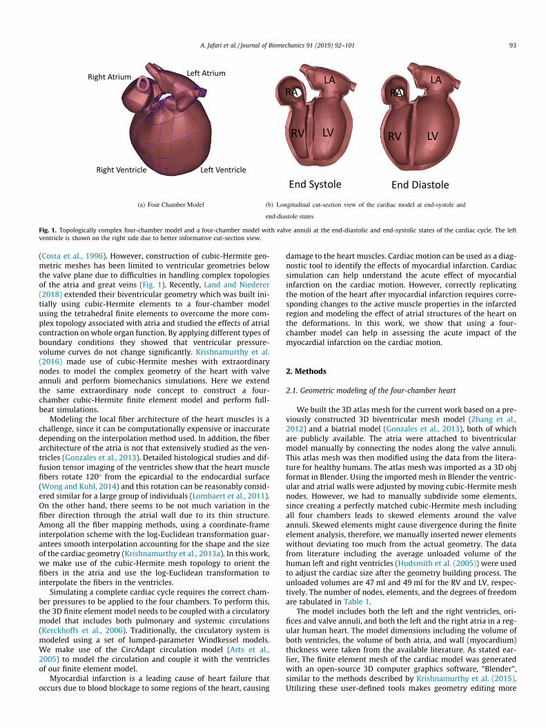
The circulation model is coupled to the two chambers of thefour-chamber model, since this coupling has to conserve the vol-ume of the ventricles due to the presence of valves. We ran thesimulation for seven full beat cycles, which was enough to achievea steady state for the cardiac simulations. The circulation modeloutputs the atrial pressure as well as the ventricular pressure val-ues, which are used as pressure boundary conditions to achieve thedeformation of the four-chamber cardiac model for the full beatcycle. Owing to the complex geometry of a four-chamber cardiacmodel, the necessary and proper boundary conditions need to becarefully applied to replicate the deformation of the heart. In ourmodel, both Mitral and Tricuspid valves (displayed in orange colorin Fig. 3(a)) were fixed along the x-axis (vertical direction) while
they can move freely in other directions (y-axis and z-axis). More-over, the first and second-cross derivatives with respect to y and zdirections were set to zero to prevent any non-planar deformationnear the valves. The Pulmonary artery and Aorta (displayed in bluecolor in Fig. 3(a)) are only fixed in y and z directions while they canmove freely along the x-axis (vertical direction). The first and sec-ond derivatives with respect to y and z directions are set to zero toavoid any non-planar deformations. The venae cavae and pul-monary veins are fixed in three directions without applying anyfirst or second order derivatives (green colored nodes). The Neu-mann pressure boundary conditions were applied on the inner sur-faces of all the four chambers as shown in Fig. 3(b). These boundaryconditions prevent any rigid body motion of the heart while notconstraining any other specific region, making them equivalentto the in vivo rigid body constraints.
2.4. Simulation with myocardial infarction
We studied a heart with an infarcted region (Fig. 5(a)) to inves-tigate the acute effects of MI on the ventricular efficiency and thecorresponding acute P-V loop. The volumetric ratio of the infarctedregion compared to the left ventricular wall volume is about 15%.MI leads to the stiffening (chronic effects) of the myocardium inthe infarcted region along with a reduction in its contractility(acute effects). We modeled the acute tissue damage by keepingthe muscle stiffness the same as the healthy heart, while reducingthe contractility ract in Eq. (2) down to ten times less than ahealthy heart (Genet et al., 2015).
3. Results
3.1. Validation of cardiac motion
The validity of the proposed rigid body constraints to replicatethe correct normal cardiac motion can be examined by comparingthe normalized apex-base and apex-atrium distances (with respect
Fig. 2. Fiber orientation from +60' (at endocardium) with respect to the circumferential direction to"60' (at epicardium) at ventricular region; the Atrial fiber angle is kept atzero everywhere, following the cubic-Hermite mesh topology.
Table 2Passive parameters of the Ogden-Holzapfel models.
a (kPa) b af (kPa) bf
Present work 0.684 (LV, RV) 9.726 0.51 (LV, RV) 15.7791.368 (LA, RA) 1.02 (LA, RA)
Krishnamurthy et al. (2013b) 0.684 9.726 0.51 15.779Holzapfel and Ogden (2009) 2.28 9.726 1.685 15.779
A. Jafari et al. / Journal of Biomechanics 91 (2019) 92–101 95
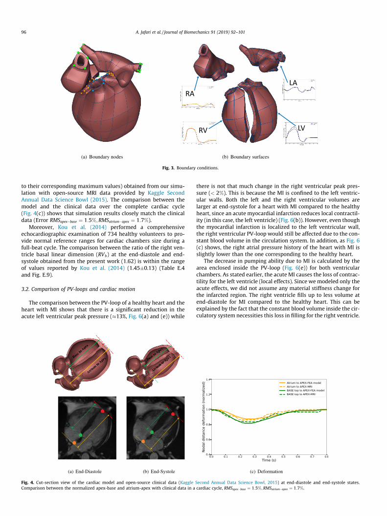
to their corresponding maximum values) obtained from our simu-lation with open-source MRI data provided by Kaggle SecondAnnual Data Science Bowl (2015). The comparison between themodel and the clinical data over the complete cardiac cycle(Fig. 4(c)) shows that simulation results closely match the clinicaldata (Error RMSapex"base ¼ 1:5%;RMSatrium"apex ¼ 1:7%).
Moreover, Kou et al. (2014) performed a comprehensiveechocardiographic examination of 734 healthy volunteers to pro-vide normal reference ranges for cardiac chambers size during afull-beat cycle. The comparison between the ratio of the right ven-tricle basal linear dimension (RVb) at the end-diastole and end-systole obtained from the present work (1.62) is within the rangeof values reported by Kou et al. (2014) (1.45(0.13) (Table E.4and Fig. E.9).
3.2. Comparison of PV-loops and cardiac motion
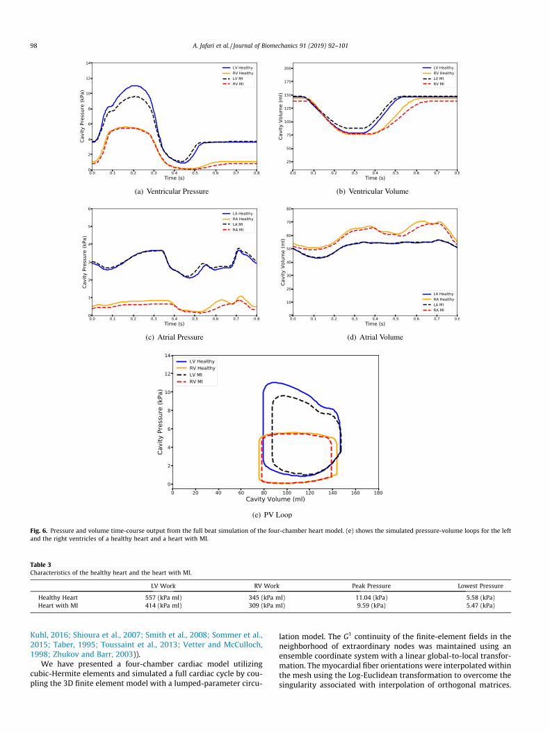
The comparison between the PV-loop of a healthy heart and theheart with MI shows that there is a significant reduction in theacute left ventricular peak pressure ()13%, Fig. 6(a) and (e)) while
there is not that much change in the right ventricular peak pres-sure (< 2%). This is because the MI is confined to the left ventric-ular walls. Both the left and the right ventricular volumes arelarger at end-systole for a heart with MI compared to the healthyheart, since an acute myocardial infarction reduces local contractil-ity (in this case, the left ventricle) (Fig. 6(b)). However, even thoughthe myocardial infarction is localized to the left ventricular wall,the right ventricular PV-loop would still be affected due to the con-stant blood volume in the circulation system. In addition, as Fig. 6(c) shows, the right atrial pressure history of the heart with MI isslightly lower than the one corresponding to the healthy heart.
The decrease in pumping ability due to MI is calculated by thearea enclosed inside the PV-loop (Fig. 6(e)) for both ventricularchambers. As stated earlier, the acute MI causes the loss of contrac-tility for the left ventricle (local effects). Since we modeled only theacute effects, we did not assume any material stiffness change forthe infarcted region. The right ventricle fills up to less volume atend-diastole for MI compared to the healthy heart. This can beexplained by the fact that the constant blood volume inside the cir-culatory system necessities this loss in filling for the right ventricle.
Fig. 3. Boundary conditions.
Fig. 4. Cut-section view of the cardiac model and open-source clinical data (Kaggle Second Annual Data Science Bowl, 2015) at end-diastole and end-systole states.Comparison between the normalized apex-base and atrium-apex with clinical data in a cardiac cycle, RMSapex"base ¼ 1:5%;RMSatrium"apex ¼ 1:7%.
96 A. Jafari et al. / Journal of Biomechanics 91 (2019) 92–101

Due to the less active cardiac cells in the heart with MI, its pump-ing ability is reduced by 20% compared to the healthy heart (16%reduction from the left ventricle and 4% from the right ventricle,see Table 3).
The changes in the left and the right ventricles’ deformation inthe heart with MI and the healthy heart at different states of thecardiac cycle is shown in Fig. 7. The left column shows the cross-sectional views of a healthy heart while the right column showsthe heart with MI. The nodal distance between the septum andthe left and the right ventricular free wall, denoted by dLV"Septum
and dRV"Septum, can be used to determine the effects of MI on thelocal ventricular deformation. As can be seen, the LV in a heart withMI fills as much as a healthy heart (Fig. 7 (a) and (b)) at end-diastole, while at peak pressure and the end-systolic state, it showsless contraction (Fig. 7 (c) and (d)) due to the weaker contractilityof the heart with MI. At lower pressure (Fig. 7 (g) and (h)), this dif-ference is negligible compared to the other cardiac state. On theother hand, the RV in a heart with MI expands less than the healthyheart at end-diastolic states. In addition, as a consequence, the RValso loses some of its contractility due to the Frank-Starlingmechanism.
Fig. 5(b) shows the history of dLV"Septum and dRV"Septum in the car-diac cycle. As can be seen the differences in dLV"Septum between aheart with MI and a healthy heart is more significant when theheart is contracting while the right ventricle shows greater devia-tion from the healthy heart during isovolumic contraction after theend-diastolic state. This shows that losing the contractility is morecritical for the LV at end-systolic state while the effects are moreprominent on the RV after the end-diastolic state.
4. Discussion
The heart’s complex geometry requires the implementation ofvery fine meshes on regions of high curvature, which makes simu-lations numerically expensive with linear elements. For instance,Augustin et al. (2016) presented an accurate high-resolution modelof the human heart electromechanics by using up to 184.6 milliontetrahedral elements to solve the nonlinear governing equations.However, the use of cubic-Hermite elements in our study helpsus to use fewer number of elements to capture the complex geom-etry. In addition, the mesh element sizes that we have employedfor our four-chamber model are refined enough to obtain con-verged mesh displacements and chamber volumes (see AppendixF for mesh size comparison and convergence of cubic-Hermite
elements for biomechanics). We had previously reported thatcubic-Hermite meshes require fewer Newton-Raphson iterationsto converge even in the presence of extraordinary nodes(Krishnamurthy et al., 2015). Recent comprehensive work doneby Vincent et al. (2015) compares the convergence behavior of dif-ferent interpolation methods for finite element simulations on acardiac monodomain equations for electrophysiology. These con-vergence analysis results show that cubic-Hermite meshes canaccurately capture the biomechanics of a cardiac geometry withfewer elements.
Fritz et al. (2014) built a four-chamber cardiac model from MRIdata of a healthy middle age volunteer to study the interactionbetween the ventricles, the atria, and the pericardium in a full-beat cycle. By developing a contact handling algorithm, they wereable to solve the contact between the epicardium and the peri-cardium. The apex, the openings of the pulmonary vein, and boththe inferior and the superior venae cavae, were fixed in their modelas well as the outer surface of the mesh of the surrounding tissue.They found out that, after including the pericardium, the contour ofthe outer surface of the heart of varied only minimally, althoughthe ventricles, as well as the atria, were significantly deformed.In this study, we have not included the effect of pericardiumdirectly. One possible way this can be included in our model is toapply direct pressure to the outer faces of the elements that cansimulate the effect of the pericardium. However, even without thiseffect included, we found that the apex-base displacement in ourmodel matches commonly observed values reported in the litera-ture. In addition, we post processed our deformation results tofix the apex instead of the valve plane (please see included full beatvideo, Online supplement Appendix D) The resulting deformationsmatch observed cardiac deformations in the chest cavity.
There have been several related work on computational cardiacmodeling. Please see the online supplement for a detailed discus-sion of these addditional related works (Arsigny et al., 2005;Bernus et al., 2002; Bourdin et al., 2007; Bradley et al., 1997;Catmull and Clark, 1978; Culver, 1966; DeRose, 1990; Doo andSabin, 1978; Du and Schmitt, 1990; Farin, 1982; Farin, 1986;Fillard et al., 2006; Freeman et al., 1985; Gasser and Forsell,2011; Holmes et al., 2000; Hughes et al., 2005; Land et al., 2017;Li et al., 2005; Liu and Hoschek, 1989; McLeod, 1977; Nielsenet al., 1991; Pathmanathan et al., 2012; Pennec et al., 2006; Perket al., 2012; Petitjean and Dacher, 2011; Pfaller et al., 2019;Remme et al., 2004; Rijcken et al., 1999; Ringenberg et al., 2014;Robb and Robb, 1942; Rogers and McCulloch, 1994; Sáez and
Fig. 5. Heart with myocardial infarction.
A. Jafari et al. / Journal of Biomechanics 91 (2019) 92–101 97
Kuhl, 2016; Shioura et al., 2007; Smith et al., 2008; Sommer et al.,2015; Taber, 1995; Toussaint et al., 2013; Vetter and McCulloch,1998; Zhukov and Barr, 2003)).
We have presented a four-chamber cardiac model utilizingcubic-Hermite elements and simulated a full cardiac cycle by cou-pling the 3D finite element model with a lumped-parameter circu-
lation model. The G1 continuity of the finite-element fields in theneighborhood of extraordinary nodes was maintained using anensemble coordinate system with a linear global-to-local transfor-mation. The myocardial fiber orientations were interpolated withinthe mesh using the Log-Euclidean transformation to overcome thesingularity associated with interpolation of orthogonal matrices.
Fig. 6. Pressure and volume time-course output from the full beat simulation of the four-chamber heart model. (e) shows the simulated pressure-volume loops for the leftand the right ventricles of a healthy heart and a heart with MI.
Table 3Characteristics of the healthy heart and the heart with MI.
LV Work RV Work Peak Pressure Lowest Pressure
Healthy Heart 557 (kPa ml) 345 (kPa ml) 11.04 (kPa) 5.58 (kPa)Heart with MI 414 (kPa ml) 309 (kPa ml) 9.59 (kPa) 5.47 (kPa)
98 A. Jafari et al. / Journal of Biomechanics 91 (2019) 92–101

Physiologically equivalent rigid body constraints were applied tothe nodes along the valve plane. We simulated a complete cardiaccycle of a healthy heart using this four-chamber model. Accuratelymodeling the geometric structures of the heart allows the applica-
tion of practical and physiologically equivalent rigid body con-straints. These, in turn, allows the model to replicate thedeformations of the different regions of the heart. The resultingdeformations were validated using open-source cardiac motion
Fig. 7. Cross-section views of the infarcted region at different cardiac cycle for healthy heart and the heart with MI.
A. Jafari et al. / Journal of Biomechanics 91 (2019) 92–101 99

data from the literature. Our four-chamber model has the capabil-ity to match patient-specific cardiac deformations, therebyimproving the state-of-the-art of patient specific cardiac modeling.
Declaration of Competing Interest
The authors confirm that there are no known conflicts of interestassociated with this publication and there has been no significantfinancial interests for this work that could have influenced itsoutcome.
Acknowledgments
We would like to thank Drs. Andrew McCulloch and W. PaulSegars for their suggestions on physiologically appropriate bound-ary conditions. This work has been funded in part by the NSF grant1750865 and the NIH grant 1 R01 HL131753.
Supplementary material
Supplementary data associated with this article can be found, inthe online version, at https://doi.org/10.1016/j.jbiomech.2019.05.019.
References
Aguado-Sierra, J., Krishnamurthy, A., Villongco, C., Chuang, J., Howard, E., Gonzales,M.J., Omens, J., Krummen, D.E., Narayan, S., Kerckhoffs, R.C., McCulloch, A.D.,2011. Patient-specific modeling of dyssynchronous heart failure: a case study.Prog. Biophys. Mol. Biol. 107, 147–155.
Alastrue, V., Martinez, M., Doblare, M., 2008. Modelling adaptative volumetric finitegrowth in patient-specific residually stressed arteries. J. Biomechanics 41,1773–1781.
Arsigny, V., Fillard, P., Pennec, X., Ayache, N., 2005. Fast and simple calculus ontensors in the log-Euclidean framework. In: Medical Image Computing andComputer-Assisted Intervention–MICCAI 2005, pp. 115–122..
Arts, T., Delhaas, T., Bovendeerd, P., Verbeek, X., Prinzen, F., 2005. Adaptation tomechanical load determines shape and properties of heart and circulation: theCircAdapt model. Am. J. Physiol.-Heart Circulat. Physiol. 288, H1943.
Augustin, C.M., Neic, A., Liebmann, M., Prassl, A.J., Niederer, S.A., Haase, G., Plank, G.,2016. Anatomically accurate high resolution modeling of human whole heartelectromechanics: a strongly scalable algebraic multigrid solver method fornonlinear deformation. J. Comput. Phys. 305, 622–646.
Bernus, O., Verschelde, H., Panfilov, A.V., 2002. Modified ionic models of cardiactissue for efficient large scale computations. Phys. Med. Biol. 47, 1947.
Bourdin, X., Trosseille, X., Petit, P., Beillas, P., 2007. Comparison of tetrahedral andhexahedral meshes for organ finite element modelling: An application to kidneyimpact. In: 20th International Technical Conference on the Enhanced Safety ofVehicles (ESV) National Highway Traffic Safety Administration 07–0424..
Bradley, C., Pullan, A., Hunter, P., 1997. Geometric modeling of the human torsousing cubic Hermite elements. Ann. Biomed. Eng. 25, 96–111.
Catmull, E., Clark, J., 1978. Recursively generated b-spline surface on arbitrarytopological meshes. Comput. Aided Des. 10, 350–355.
Costa, K., Hunter, P., Wayne, J., Waldman, L., Guccione, J., McCulloch, A., 1996. Athree-dimensional finite element method for large elastic deformations ofventricular myocardium: II-prolate spheroidal coordinates. J. Biomech. Eng.118, 464–472.
Culver, W.J., 1966. On the existence and uniqueness of the real logarithm of amatrix. Proc. Am. Math. Soc. 17, 1146–1151.
DeRose, T.D., 1990. Necessary and sufficient conditions for tangent plane continuityof Bézier surfaces. Comput.-Aided Geometric Des. 7, 165–179.
Doo, D., Sabin, M., 1978. Behaviour of recursive division surfaces near extraordinarypoints. Comput. Aided Des. 10, 356–360.
Du, W.-H., Schmitt, F.J., 1990. On the G1 continuity of piecewise Bézier surfaces: areview with new results. Comput. Aided Des. 22, 556–573.
Farin, G., 1982. A construction for visual c1 continuity of polynomial surfacepatches. Comput. Graphics Image Process. 20, 272–282.
Farin, G., 1986. Triangular bernstein-bézier patches. Comput. Aided Geometric Des.3, 83–127.
Fillard, P., Arsigny, V., Pennec, X., Ayache, N., 2006. Joint estimation and smoothingof clinical DT-MRI with a log-Euclidean metric. Res. Rep., RR-5584
Freeman, G.L., LeWinter, M.M., Engler, R.L., Covell, J.W., 1985. Relationship betweenmyocardial fiber direction and segment shortening in the midwall of the canineleft ventricle. Circul. Res. 56, 31–39.
Fritz, T., Wieners, C., Seemann, G., Steen, H., Dössel, O., 2014. Simulation of thecontraction of the ventricles in a human heart model including atria andpericardium. Biomech. Model. Mechanobiol. 13, 627–641.
Gasser, T.C., Forsell, C., 2011. The numerical implementation of invariant-basedviscoelastic formulations at finite strains. an anisotropic model for the passivemyocardium. Comput. Methods Appl. Mech. Eng. 200, 3637–3645.
Genet, M., Lee, L.C., Ge, L., Acevedo-Bolton, G., Jeung, N., Martin, A., Cambronero, N.,Boyle, A., Yeghiazarians, Y., Kozerke, S., et al., 2015. A novel method forquantifying smooth regional variations in myocardial contractility within aninfarcted human left ventricle based on delay-enhanced magnetic resonanceimaging. J. Biomech. Eng. 137, 081009.
Gonzales, M.J., Sturgeon, G., Krishnamurthy, A., Hake, J., Jonas, R., Stark, P., Rappel,W.J., Narayan, S.M., Zhang, Y., Segars, W.P., McCulloch, A.D., 2013. A three-dimensional finite element model of human atrial anatomy: new methods forcubic Hermite meshes with extraordinary vertices. Med. Image Anal. 17, 525–537.
Guccione, J., McCulloch, A., Waldman, L., 1991. Passive material properties of intactventricular myocardium determined from a cylindrical model. J. Biomech. Eng.113, 42.
Holmes, A., Scollan, D., Winslow, R., 2000. Direct histological validation of diffusiontensor MRI in formaldehyde-fixed myocardium. Magn. Reson. Med. 44, 157–161.
Holzapfel, G., Ogden, R., 2009. Constitutive modelling of passive myocardium: astructurally based framework for material characterization. Philos. Trans. Roy.Soc. A 367, 3445.
Hudsmith, L.E., Petersen, S.E., Francis, J.M., Robson, M.D., Neubauer, S., 2005. Normalhuman left and right ventricular and left atrial dimensions using steady statefree precession magnetic resonance imaging. J. Cardiovas. Magn. Resonance 7,775–782.
Hughes, T.J., Cottrell, J.A., Bazilevs, Y., 2005. Isogeometric analysis: CAD, finiteelements, NURBS, exact geometry and mesh refinement. Comput. MethodsAppl. Mech. Eng. 194, 4135–4195.
Javani, S., Gordon, M., Azadani, A.N., 2016. Biomechanical properties andmicrostructure of heart chambers: a paired comparison study in an ovinemodel. Ann. Biomed. Eng. 44, 3266–3283.
Kaggle Second Annual Data Science Bowl, 2015. The National Heart, Lung, and BloodInstitute. <https://www.kaggle.com/c/second-annual-data-science-bowl>(accessed 29 November 2018)..
Kerckhoffs, R., Neal, M., Gu, Q., Bassingthwaighte, J., Omens, J., McCulloch, A., 2007.Coupling of a 3D finite element model of cardiac ventricular mechanics tolumped systems models of the systemic and pulmonic circulation. Ann. Biomed.Eng. 35, 1–18.
Kerckhoffs, R., Omens, J., McCulloch, A., Mulligan, L., 2010. Ventricular dilation andelectrical dyssynchrony synergistically increase regional mechanicalnonuniformity but not mechanical dyssynchrony. Circul. Heart Failure 3, 528–536.
Kerckhoffs, R.C., Healy, S.N., Usyk, T.P., McCULLOCH, A.D., 2006. Computationalmethods for cardiac electromechanics. Proc. IEEE 94, 769–783.
Klotz, S., Hay, I., Dickstein, M.L., Yi, G.-H., Wang, J., Maurer, M.S., Kass, D.A., Burkhoff,D., 2006. Single-beat estimation of end-diastolic pressure-volume relationship:a novel method with potential for noninvasive application. Am. J. Physiol.-HeartCircul. Physiol. 291, H403–H412.
Kou, S., Caballero, L., Dulgheru, R., Voilliot, D., De Sousa, C., Kacharava, G.,Athanassopoulos, G.D., Barone, D., Baroni, M., Cardim, N., Gomez De Diego, J.J.,Hagendorff, A., Henri, C., Hristova, K., Lopez, T., Magne, J., De La Morena, G.,Popescu, B.A., Penicka, M., Ozyigit, T., Rodrigo Carbonero, J.D., Salustri, A., VanDe Veire, N., Von Bardeleben, R.S., Vinereanu, D., Voigt, J.-U., Zamorano, J.L.,Donal, E., Lang, R.M., Badano, L.P., Lancellotti, P., 2014. Echocardiographicreference ranges for normal cardiac chamber size: results from the norre study.Eur. Heart J. – Cardiovasc. Imaging 15, 680–690.
Krishnamurthy, A., Gonzales, M.J., Sturgeon, G., Segars, W.P., McCulloch, A.D., 2016.Biomechanics simulations using cubic hermite meshes with extraordinarynodes for isogeometric cardiac modeling. Comput. Aided Geometric Des. 43,27–38. Geometric Modeling and Processing 2016.
Krishnamurthy, A., Villongco, C., Beck, A., Omens, J., McCulloch, A., 2015. Leftventricular diastolic and systolic material property estimation from image data.In: Statistical Atlases and Computational Models of the Heart-Imaging andModelling Challenges. Springer, pp. 63–73.
Krishnamurthy, A., Villongco, C.T., Chuang, J., Frank, L.R., Nigam, V., Belezzuoli, E.,Stark, P., Krummen, D.E., Narayan, S., Omens, J.H., et al., 2013a. Patient-specificmodels of cardiac biomechanics. J. Comput. Phys., 244, 4–21. Multi-scaleModeling and Simulation of Biological Systems..
Krishnamurthy, A., Villongco, C.T., Chuang, J., Frank, L.R., Nigam, V., Belezzuoli, E.,Stark, P., Krummen, D.E., Narayan, S., Omens, J.H., et al., 2013b. Patient-specificmodels of cardiac biomechanics. J. Comput. Phys. 244, 4–21.
Krueger, M., Schmidt, V., Tobón, C., Weber, F., Lorenz, C., Keller, D., Barschdorf, H.,Burdumy, M., Neher, P., Plank, G., 2011. Modeling atrial fiber orientation inpatient-specific geometries: a semi-automatic rule-based approach. In:Functional Imaging and Modeling of the Heart, pp. 223–232..
Land, S., Niederer, S.A., 2018. Influence of atrial contraction dynamics on cardiacfunction. Int. J. Numer. Methods Biomed. Eng. 34, e2931.
Land, S., Park-Holohan, S.-J., Smith, N.P., dos Remedios, C.G., Kentish, J.C., Niederer,S.A., 2017. A model of cardiac contraction based on novel measurements oftension development in human cardiomyocytes. J. Mol. Cell. Cardiol. 106, 68–83.
Li, G., Ma, W., Bao, H., 2005. A new interpolatory subdivision for quadrilateralmeshes. Comput. Graphics Forum 24, 3–16.
Liu, D., Hoschek, J., 1989. GC1 continuity conditions between adjacent rectangularand triangular Bezier surface patches. Comput. Aided Des. 21, 194–200.
100 A. Jafari et al. / Journal of Biomechanics 91 (2019) 92–101
Lombaert, H., Peyrat, J., Croisille, P., Rapacchi, S., Fanton, L., Clarysse, P., Delingette,H., Ayache, N., 2011. Statistical analysis of the human cardiac fiber architecturefrom DT-MRI. In: Functional Imaging and Modeling of the Heart, pp. 171–179..
Lombaert, H., Peyrat, J.-M., Fanton, L., Cheriet, F., Delingette, H., Ayache, N., Clarysse,P., Magnin, I., Croisille, P., 2012. Statistical atlas of human cardiac fibers:comparison with abnormal hearts. In: Proceedings of the Second internationalconference on Statistical Atlases and Computational Models of the Heart:Imaging and Modelling Challenges. Springer-Verlag, pp. 207–213.
Lumens, J., Delhaas, T., Kirn, B., Arts, T., 2009. Three-wall segment (TriSeg) modeldescribing mechanics and hemodynamics of ventricular interaction. Ann.Biomed. Eng. 37, 2234–2255.
McLeod, R., 1977. Hermite interpolation over curved finite elements. J. Approx.Theory 19, 101–117.
Niederer, S., Plank, G., Chinchapatnam, P., Ginks, M., Lamata, P., Rhode, K., Rinaldi, C.,Razavi, R., Smith, N., 2011. Length-dependent tension in the failing heart andthe efficacy of cardiac resynchronization therapy. Cardiovasc. Res. 89, 336–343.
Nielsen, P., LeGrice, I., Smaill, B., Hunter, P., 1991. Mathematical model of geometryand fibrous structure of the heart. Am. J. Physiol.- Heart Circul. Physiol. 260,H1365.
Pathmanathan, P., Bernabeu, M., Niederer, S., Gavaghan, D., Kay, D., 2012.Computational modelling of cardiac electrophysiology: explanation of thevariability of results from different numerical solvers. Int. J. Numer. MethodsBiomed. Eng. 28, 890–903.
Pennec, X., Fillard, P., Ayache, N., 2006. A Riemannian framework for tensorcomputing. Int. J. Comput. Vision 66, 41–66.
Perk, J., De Backer, G., Gohlke, H., Graham, I., Reiner, Z., Verschuren, W.M., Albus, C.,Benlian, P., Boysen, G., Cifkova, R., et al., 2012. European guidelines oncardiovascular disease prevention in clinical practice (version 2012). Int. J.Behav. Med. 19, 403–488.
Petitjean, C., Dacher, J.-N., 2011. A review of segmentation methods in short axiscardiac mr images. Med. Image Anal. 15, 169–184.
Pfaller, M.R., Hörmann, J.M., Weigl, M., Nagler, A., Chabiniok, R., Bertoglio, C., Wall,W.A., 2019. The importance of the pericardium for cardiac biomechanics: Fromphysiology to computational modeling. Biomech. Model. Mechanobiol. 18, 503–529.
Rajagopal, V., Chung, J., Nielsen, P., Nash, M., 2006. Finite element modelling ofbreast biomechanics: directly calculating the reference state. In: IEEEEngineering in Medicine and Biology Society. IEEE, pp. 420–423..
Remme, E.W., Hunter, P.J., Smiseth, O., Stevens, C., Rabben, S.I., Skulstad, H.,Angelsen, B., 2004. Development of an in vivo method for determining materialproperties of passive myocardium. J. Biomech. 37, 669–678.
Rijcken, J., Bovendeerd, P., Schoofs, A., Van Campen, D., Arts, T., 1999. Optimizationof cardiac fiber orientation for homogeneous fiber strain during ejection. Ann.Biomed. Eng. 27, 289–297.
Ringenberg, J., Deo, M., Devabhaktuni, V., Berenfeld, O., Snyder, B., Boyers, P., Gold, J.,2014. Accurate reconstruction of 3d cardiac geometry from coarsely-sliced MRI.Comput. Methods Programs Biomed. 113, 483–493.
Robb, J.S., Robb, R.C., 1942. The normal heart. Am. Heart J. 23, 455–467.Rogers, J.M., McCulloch, A.D., 1994. A collocation-galerkin finite element model of
cardiac action potential propagation. IEEE Trans. Biomed. Eng. 41, 743–757.Sáez, P., Kuhl, E., 2016. Computational modeling of acute myocardial infarction.
Comput. Methods Biomech. Biomed. Eng. 19, 1107–1115.Sermesant, M., Razavi, R., 2010. Personalized computational models of the heart for
cardiac resynchronization therapy. In: Patient-specific modeling of thecardiovascular system. Springer, pp. 167–182.
Shioura, K.M., Geenen, D.L., Goldspink, P.H., 2007. Assessment of cardiac functionwith the pressure-volume conductance system following myocardial infarctionin mice. Am. J. Physiol. – Heart Circul. Physiol. 293, H2870–H2877.
Smith, R.M., Matiukas, A., Zemlin, C.W., Pertsov, A.M., 2008. Nondestructive opticaldetermination of fiber organization in intact myocardial wall. Microscopy Res.Tech. 71, 510–516.
Sommer, G., Schriefl, A.J., Andrä, M., Sacherer, M., Viertler, C., Wolinski, H.,Holzapfel, G.A., 2015. Biomechanical properties and microstructure of humanventricular myocardium. Acta Biomater. 24, 172–192.
Taber, L.A., 1995. Biomechanics of growth, remodeling, and morphogenesis. Appl.Mech. Rev. 48, 487–545.
Toussaint, N., Stoeck, C.T., Schaeffter, T., Kozerke, S., Sermesant, M., Batchelor, P.G.,2013. In vivo human cardiac fibre architecture estimation using shape-baseddiffusion tensor processing. Med. Image Anal. 17, 1243–1255.
Vetter, F., McCulloch, A., 1998. Three-dimensional analysis of regional cardiacfunction: a model of rabbit ventricular anatomy. Prog. Biophys. Mol. Biol. 69,157–183.
Vincent, K.P., Gonzales, M.J., Gillette, A.K., Villongco, C.T., Pezzuto, S., Omens, J.H.,Holst, M.J., & McCulloch, A.D., 2015. High-order finite element methods forcardiac monodomain simulations. Front. Physiol. 6..
Walker, J.C., Ratcliffe, M.B., Zhang, P., Wallace, A.W., Fata, B., Hsu, E.W., Saloner, D.,Guccione, J.M., 2005. Mri-based finite-element analysis of left ventricularaneurysm. Am. J. Physiol.-Heart Circul. Physiol. 289, H692–H700.
Wang, L., Wong, K.C., Zhang, H., Liu, H., Shi, P., 2011. Noninvasive computationalimaging of cardiac electrophysiology for 3-d infarct. IEEE Trans. Biomed. Eng.58, 1033–1043.
Wong, J., Kuhl, E., 2014. Generating fibre orientation maps in human heart modelsusing poisson interpolation. Comput. Methods Biomech. Biomed. Eng. 17,1217–1226.
Zhang, Y., Liang, X., Ma, J., Jing, Y., Gonzales, M.J., Villongco, C., Krishnamurthy, A.,Frank, L.R., Nigam, V., Stark, P., Narayan, S.M., McCulloch, A.D., 2012. An atlas-based geometry pipeline for cardiac Hermite model construction and diffusiontensor reorientation. Med. Image Anal. 16, 1130–1141.
Zhukov, L., Barr, A.H. (2003). Heart-muscle fiber reconstruction from diffusiontensor mri. In: Proceedings of the 14th IEEE Visualization 2003 (VIS’03). IEEEComputer Society, p. 79.
A. Jafari et al. / Journal of Biomechanics 91 (2019) 92–101 101

Appendix A. Additional Discussion
In this paper, we make use of a cubic-Hermite mesh with extraordinary nodes to construct a four-chamber cardiacmodel. We then demonstrate the versatility of the model to perform biomechanics simulations by simulating a fullbeat cycle of a ”healthy” and an ”infarcted” heart. The main contributions of the paper include:
• Constructing a four-chamber cardiac model using higher order cubic-Hermite meshes with extraordinary nodes.
• Accurately modeling the fiber architecture in a four-chamber cardiac model, including the atria.
• Performing full beat biomechanics simulations of four-chamber cardiac models using physiologically equivalentrigid body constraints.
• Investigating the e↵ects of acute myocardial infarction on the local deformation in a four-chamber cardiacmodel and the ventricular pumping ability.
We compared the deformation of a four-chamber heart with acute myocardial infarction with an healthy heart. Thetissue damage due to myocardial infarction is modeled using a reduced contractility in the infarcted region (no chronice↵ects of MI). We compared the acute pumping function of the heart for both cases by calculating the work done bythe ventricles (area enclosed inside the left and the right ventricular Pressure-Volume (P-V) loop). We observed a20% reduction in work done by the heart immediately after myocardial infarction. The comparison between thedisplacement of the infarcted region and the corresponding region in a healthy heart shows that the heart with MIloses its ability to contract depending on the location and strength of the infarcted region.
There are several improvements that can be made to our model to make it more accurate. We are planning toimprove our model by incorporating the following model details.
• Improving the current muscle contraction by applying a biophysically accurate human contraction model (forexample, Land et al. (2017)) and incorporating the spatial delay in contraction from apex to base of the ventri-cles.
• Improving the accuracy of the results by considering the pericardium pressure as an additional boundary con-dition (Pfaller et al., 2019).
Incorporating these elements will enable our four-chamber model to match patient-specific deformations.
(a) Original mesh (b) Mesh after one level of subdivision (c) Mesh after two levels of subdivision
Figure A.8: Four-chamber cardiac model cubic-Hermite meshes build in Blender from the original mesh to the two-level subdivided mesh.
1

Appendix B. Blender 3D model
The necessary derivatives for presenting a smooth geometry were also obtained using a Blender plug-in. Thisplug-in has an array of functions, one of which is able to perform subdivision of the domain and calculate the nodalderivatives. Blender is an open-source software which users can add their own written plug-in as a Python script,which improves functionality for work with complex geometries.
Due to the complex curvature and geometry of the human heart, extraordinary nodes are introduced in the finiteelement mesh in order to maintain smoothness and to capture specific details. At ordinary vertices, arc-length andG1 continuity is enforced as described by Gonzales et al. (2013). At extraordinary nodes, however, continuity ismaintained via new coordinate frames called ensemble coordinates, coupled with a local-to-global map transformingglobal ensemble derivatives into local element derivatives using a method also described by Gonzales et al. (2013).Estimation of the local element derivatives are obtained from nodes after subdividing the mesh twice to enforce C0
continuity.Figure A.8 shows the original model followed by two level subdivision to calculate the first, second, and cross
derivatives at each vertex. As can be seen, after the second level of subdivision a smooth geometry can be obtainedwhile guaranteeing the G1 continuity on every node including ordinary and extraordinary nodes.
Appendix C. Fiber Interpolation
In this section, we briefly describe a coordinate-frame interpolation scheme that uses the log-Euclidean transfor-mation ensuring the preservation of the shape and size of the geometry.
The fiber coordinate frame corresponds to the fiber and cross-fiber orientations at each node is represented using a3⇥ 3 orthogonal matrix, F whose columns represent the vectors along the three orthogonal coordinate directions. Thefirst step is converting matrix F to log-Euclidean space by taking the matrix logarithm. However, a real matrix has areal logarithm if and only if it is invertible and each Jordan block belonging to a negative eigenvalue occurs an evennumber of times, otherwise it has only non-real logarithms (Culver, 1966). The necessary conditions can be satisfiedby constructing a synthetic symmetric matrix, T whose eigenvalues are synthetic but unique and positive, as shownbelow,
T = F
2666666664
d11 0 00 d22 00 0 d33
3777777775 F
T (C.1)
In Equation C.1, the values of d11, d22, and d33 are chosen to be unique, positive, and in sorted order (d11 < d22 < d33,(5,10,20), for instance). The matrix T is then transformed to L by the matrix logarithm: L=log(T) while the symmetryand positive-definiteness of L is preserved. The calculated matrix logarithm is then used to interpolate the coordinateframe within an element. It is worth mentioning that the matrix logarithm of a positive definite matrix is symmetricwith only six independent components. The same basis functions are also used to estimate the matrix L’s componentsinterpolation, similar to scalar quantities in Euclidean space. We also take advantage of the local-to-global mappingto interpolate the six independent components of logarithm matrix in the presence of extraordinary nodes. At anyarbitrary point within the element, the coordinate frame can then be obtained by calculating the matrix exponential ofthe interpolated Le,
Te = e(Le) (C.2)
and then computing the eigenvectors, vi (i=1,2,3) of the resulting matrix and sorting them according to the eigenvaluesof Te. Sorting is necessary to keep the order of vectors in the coordinate frame unchanged. Since the eigenvalues areonly used for sorting the eigenvectors, there are no stability issues during interpolation as long as they are positive andunique.
2

Appendix D. Supplemental Videos
We have included a movie which shows the deformation of the four-chamber cardiac model in a full-beat cycleafter transferring the fixed boundary conditions to the apex instead of the base. The deformations shown here closelymatches the in vivo heart deformations. This shows that the boundary conditions that we applied are physiologicallyequivalent to the in vivo rigid body constraints.
We have also included another movie which shows the deformation of the four-chamber cardiac model in a full-beat cycle for both the healthy heart and the heart with myocardial infarction. As can be seen, the heart with myocar-dial infarction shows less contractility compared to the healthy heart.
Appendix E. Validation of Cardiac Motion
This section shows some additional validation of the cardiac motion. Figure E.9 shows the comparison in the RVdimension in the same orientation as Figure 4 from Kou et al. (2014).
𝒃
RV
Figure E.9: Right ventricle’s basal linear dimension. The orientation of the model corresponds to Figure 3 in Kou et al. (2014).
Table E.4: The comparison between the ratio of the right ventricle basal linear dimension (RVb) at the end-diastole and end-systole obtained fromthe present work and Kou et al. (2014).
Present Work Kou et al. (2014)
RVb(end�diastole)RVb(end�systole) 1.62 1.45 ± 0.13
Appendix F. Convergence Study
We performed a mesh refinement convergence study of the cubic-Hermite models with extraordiary nodes. For thispurpose, we created five di↵erent geometries of a single left ventricular model and inflated them to the end-diastolicpressure and compared the ventricular volumes and the apex-base distances at di↵erent pressure steps. Figure F.11shows the ventricular geometry with increasing refinement from left to right in either the radial, circumferential, orboth directions.
As can be seen in Figures 12(a)-12(b), there is not a significant change in the nodal deformations or the volumehistory with the increase in number of elements. We achieve an acceptable tolerance (for example, 0.016 mm fornodal displacement, comparable to 0.5 mm spatial resolution of the CT images with fewer mesh elements with cubic-Hermite elements. Moreover, Figure 12(c) shows that the LV end-diastolic volume obtained using di↵erent mesh
3
(a) 28 elements (b) 56 elments (c) 122 elments (d) 224 elments (e) 448 elements
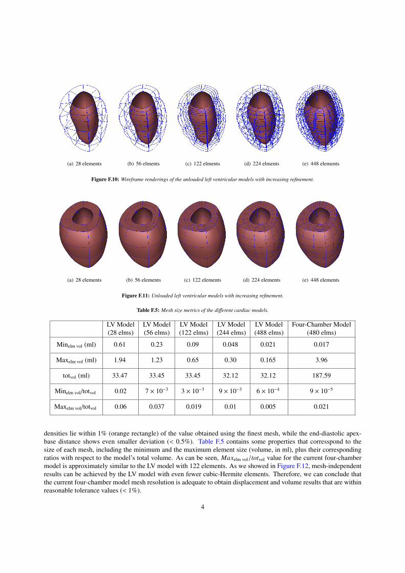
Figure F.10: Wireframe renderings of the unloaded left ventricular models with increasing refinement.
(a) 28 elements (b) 56 elements (c) 122 elements (d) 224 elements (e) 448 elements
Figure F.11: Unloaded left ventricular models with increasing refinement.
Table F.5: Mesh size metrics of the di↵erent cardiac models.
LV Model(28 elms)
LV Model(56 elms)
LV Model(122 elms)
LV Model(244 elms)
LV Model(488 elms)
Four-Chamber Model(480 elms)
Minelm vol (ml) 0.61 0.23 0.09 0.048 0.021 0.017
Maxelm vol (ml) 1.94 1.23 0.65 0.30 0.165 3.96
totvol (ml) 33.47 33.45 33.45 32.12 32.12 187.59
Minelm vol/totvol 0.02 7 ⇥ 10�3 3 ⇥ 10�3 9 ⇥ 10�3 6 ⇥ 10�4 9 ⇥ 10�5
Maxelm vol/totvol 0.06 0.037 0.019 0.01 0.005 0.021
densities lie within 1% (orange rectangle) of the value obtained using the finest mesh, while the end-diastolic apex-base distance shows even smaller deviation (< 0.5%). Table F.5 contains some properties that corresspond to thesize of each mesh, including the minimum and the maximum element size (volume, in ml), plus their correspondingratios with respect to the model’s total volume. As can be seen, Maxelm vol/totvol value for the current four-chambermodel is approximately similar to the LV model with 122 elements. As we showed in Figure F.12, mesh-independentresults can be achieved by the LV model with even fewer cubic-Hermite elements. Therefore, we can conclude thatthe current four-chamber model mesh resolution is adequate to obtain displacement and volume results that are withinreasonable tolerance values (< 1%).
4

(a) Apex to base distance history during LV inflation (b) LV volume during LV inflation
(c) ED volume with mesh density (d) ED apex-base distance with mesh density
Figure F.12: Mesh independence study of a single LV model. Both the chamber volume and the apex to base distance are within 1% of the valuescomputed using the finest mesh.
Appendix G. Additional Related Work
In this section, we provide additional references for related work on cardiac modeling and simulations.Most previous cardiac models using high-order meshes have been restricted to geometries described by a single
set of parametric coordinates that are topologically equivalent to a cylinder (Vetter & McCulloch, 1998). However,such meshes require special boundary conditions at the cardiac apex to enable multiple overlapping nodes or sector el-ements (Bradley et al., 1997) to close the mesh. The restriction of using a single set of parametric coordinates enablesenforcing continuity across element edges easier, but introduces element distortions. In the present work, we makeuse of cubic-Hermite functions using hexahedral elements to simulate the full beat cycle of a four-chamber healthyheart and a heart with myocardial infarction. Structured grids with hex or quad meshes (either regular or curvilin-ear) can be implemented using compact meshes and usually execute faster than algorithms that support unstructuredgrids (Bourdin et al., 2007). Our method requires fewer elements and results in a smaller sti↵ness matrix, leading tofaster solution while preserving a reasonable level of accuracy.
The popularity of cubic-Hermite meshes in isogeometric finite element analysis and computer graphics have grownup significantly in recent years due to its compactness and convergence advantages. They have shown to have betterconvergence properties compared to linear hexahedral and tetrahedral elements in cardiac electrophysiology simula-tions (Vincent et al., 2015). Although cubic-Bezier curves are widely used to create smooth curves, cubic-Hermiterepresentation makes it possible to store all degrees of freedoms (DOF) at the element corners without any additionalinformation stored in the element edges or body nodes. The complex geometries associated with biomechanics mod-eling of the heart necessitate the construction of cubic-Hermite surfaces which share at least a common tangent plane
5
(G1 continuity) along their boundaries (Farin, 1982, 1986). A number of researchers have worked to propose thenecessary and su�cient conditions for G1 continuity of rational surfaces. Liu & Hoschek (1989) were among thefirst who studied and proposed the necessary and su�cient conditions of G1 continuity condition for all four possiblecombinations of rectangular and triangular Bezier patches. Later DeRose (1990) improved their work and derived thenecessary and su�cient conditions forG1 continuity for cubic-Bezier patches which did not possess a large number ofindeterminate parameters (Liu & Hoschek, 1989). Finally, Du & Schmitt (1990) extended the geometric continuitiesbetween adjacent patches and presented new alternative approaches for modeling free-form G1 continuous surfacesincluding extraordinary nodes.
As a recently developed computational method, isogeometric analysis was first introduced and developed byHughes et al. (2005) and uses the basic functions from NURBS to analyze a wide variety of mathematical problemsincluding finite element analysis. Nielsen et al. (1991) developed a mathematical model of a canine cardiac architec-ture using the cubic-Hermite basis functions on a prolate spheroidal coordinate system. Since their model consideredonly the left and the right ventricles with myocardial fiber orientations, extraordinary nodes were not required. Thiswork extends their cubic-Hermite finite element analysis to model the full geometry of a human heart by consideringthe atria in addition to the ventricles. The complexity of the geometry necessitates the use of extraordinary nodes(nodes which are shared between three or more than four elements in two dimensions), which must be treated sep-arately to maintain continuity between the di↵erent patches of NURBS surfaces. Gonzales et al. (2013) developeda general framework to construct the bicubic and tricubic Hermite basis function to model the human atria with ex-traordinary nodes. This work is the extension of their model by simulating the inflation and full beat cycle of thehuman heart which was first introduced by Krishnamurthy et al. (2016) for isogeometric cardiac modeling. Moreover,they investigated the numerical error in their simulation in the presence of extraordinary nodes and found that a fasterconvergence can still be achieved.
Unlike Lagrange basis functions which only maintain the C0 continuity at adjacent elements, cubic-Hermite func-tions can also preserve the C1 continuity for regular nodes (non-extraordinary nodes). Moreover, better convergenceproperties of cubic-Hermite elements compared to other types of elements such as linear hexahedral or tetrahedralelements, make it more appropriate and compatible for biomechanics simulations (Bradley et al., 1997; McLeod,1977). Several researchers have studied the convergence of numerical electrophysiology solutions (Rogers & McCul-loch, 1994; Bernus et al., 2002; Pathmanathan et al., 2012). Recent comprehensive work done by Vincent et al. (2015)compares the convergence behavior of di↵erent interpolation methods for finite element simulations on a cardiac mon-odomain equations for electrophysiology. They investigated linear Lagrange, cubic Hermite, and cubic Hermite-styleserendipity meshes in their study and found that high-order methods with fewer degrees of freedom and longer ele-ment edge lengths converge better than conventional linear elements. They also introduced a dimensionless numberto determine the solution convergence not only dependent on element size, but on the ratio of the discretization lengthto the characteristic length of the monodomain equation.
Subdivision is a powerful technique in computer graphics and surface modeling and can create reasonably smoothsurfaces from relatively simple meshes. Two main subdivision categories can be classified as interpolating and ap-proximating depending on if they are required to interpolate the position of the vertices in the original mesh or not.Catmull & Clark (1978) and Doo & Sabin (1978) were among the well-known researchers who first developed andderived the approximating subdivision methods by generalizing bi-cubic and bi-quadratic B-spline to generate sur-faces with C2 continuity except at extraordinary vertices where they are C1 continuous. As stated earlier, a full modelof the human heart including both atria and ventricles necessitates the use of extraordinary vertices. Therefore we usethe subdivision scheme used by Gonzales et al. (2013), the Li-Kobbetl subdivision scheme (Li et al., 2005) to approx-imate the derivatives in the presence of extraordinary nodes. In order to have a natural adaptive mesh refinement, thismethod only adds ordinary vertices to the refined mesh while the number of extraordinary vertices remain unaltered.
Non-invasive clinical imaging techniques have become the standard means for diagnosing cardiac function, via-bility, and heart failure (Petitjean & Dacher, 2011; Ringenberg et al., 2014). These techniques can be classified intothree common categories: cardiac ultrasound (echocardiography), computed tomography (CT), and magnetic reso-nance imaging (MRI). Echocardiography, being less expensive and radiation free, makes it an acceptable modality forpatient-specific cardiac modeling over CT or MRI. In addition, the lower resolution of ultrasound images results in ageometric model with fewer degrees of freedom (DOFs) (Aguado-Sierra et al., 2011).
There have been many researches to model the distribution of fiber orientation within the cardiac wall (Zhukov& Barr, 2003; Rijcken et al., 1999; Gasser & Forsell, 2011; Robb & Robb, 1942; Freeman et al., 1985). Since the
6
availability of the in vivo human hearts except for transplantation surgeries is limited, Lombaert et al. (2011) studiedmore than ten ex vivo human hearts from DT-MRI. Their studies showed that the fiber orientation can be consideredreasonably the same for a large group of humans, however the apex shows a higher deviation. Postmortem radiographyand histological techniques show that fibers rotate around 120� from the epicardial (outside) surface to the endocardial(inside) surface with the fiber angle increasing linearly from -60� to 60� with respect to the circumferential direction.Other values were also reported for the fiber rotation such as 105.7±14.9� by Smith et al. (2008) in which they usenondestructive optical determination to overcome the limitation of histological sectioning (which might damage thetissue) and di↵usive tensor imaging (which is comparatively expensive). Numerous methods have been proposed(Toussaint et al., 2013; Wong & Kuhl, 2014; Gonzales et al., 2013) to overcome the complexity of creating the fiberorientation map for computational analyses, especially the interpolation of fiber angles in meshes with extraordinaryvertices. Interpolation of tensor fields in normal Euclidean space may result in null or non-positive-definite interpo-lated tensors (Fillard et al., 2006). On the other hand, a�ne invariant Reimannian framework is an alternative methodthat can alleviate these problems but is not computationally e�cient (Pennec et al., 2006). In the present work wemake use of Log-Euclidean (LE) framework (Arsigny et al., 2005), which is simpler to implement and preserves theorthogonality of the interpolated coordinate frame (Arsigny et al., 2005; Krishnamurthy et al., 2016).
Identifying the myocardial material properties is still an active ongoing research topic (Remme et al., 2004; Som-mer et al., 2015). Although the myocardial tissue appears to be viscoelastic (Taber, 1995), the short cardiac cycletime scale compared to the tissue relaxation time makes it less significant to be simulated as a viscoelastic mate-rial. Holzapfel & Ogden (2009) did a comprehensive study on morphology and structure of the myocardium andintroduced a new constitutive model for passive myocardium. Unlike previous models which were based on linearisotropic elasticity, the model developed by Holzapfel & Ogden (2009) is a transversely-isotropic form of the conven-tional Fung-type constitutive models (Holmes et al., 2000). In this model, the anisotropy in the fiber and cross-fiberdirections of the myocardium is modeled using a separate exponential term with di↵erent exponents.
Myocardial infarction (MI), also known as heart attack is a leading cause of heart failure which increases withage, lower physical activity, and socioeconomic status (Perk et al., 2012). MI occurs due to the blood blockage causedby buildup of plaque in coronary arteries leading in the lack of oxygen and nutrients supplies to left ventricle (Saez& Kuhl, 2016). MI is critical and can damage the heart muscles if it is not treated immediately. Angioplasty andclot-busting medicine are among the most common treatments to minimize or prevent the damage caused by MI. Theinfarcted regions lose their contractility and become sti↵er, therefore, unable to keep their contribution in conductingthe electrical signal and the pumping ability. P-V loop analysis has been shown to be an appropriate method toquantitatively evaluate the underlying degradation in cardiac function after MI (Shioura et al., 2007).
7