A FORENSIC FIBER EXAMINER TRAINING PROGRAM
219
Scientific Working Group for Materials Analysis (SWGMAT) Fiber Subgroup A FORENSIC FIBER EXAMINER TRAINING PROGRAM Dedicated to the memory of Mike Grieve, a golden thread in the tapestry of our lives. Federal Bureau of Investigation Laboratory Divsion 2501 Investigation Parkway Quantico, VA 22135 MAY 2004 Version
Transcript of A FORENSIC FIBER EXAMINER TRAINING PROGRAM
Scientific Working Group for Materials Analysis(SWGMAT)
Fiber Subgroup
A FORENSIC FIBER EXAMINER TRAINING PROGRAM
Dedicated to the memory of Mike Grieve, a golden thread in the tapestry of our lives.
Federal Bureau of Investigation Laboratory Divsion 2501 Investigation Parkway Quantico, VA 22135
MAY 2004 Version
i
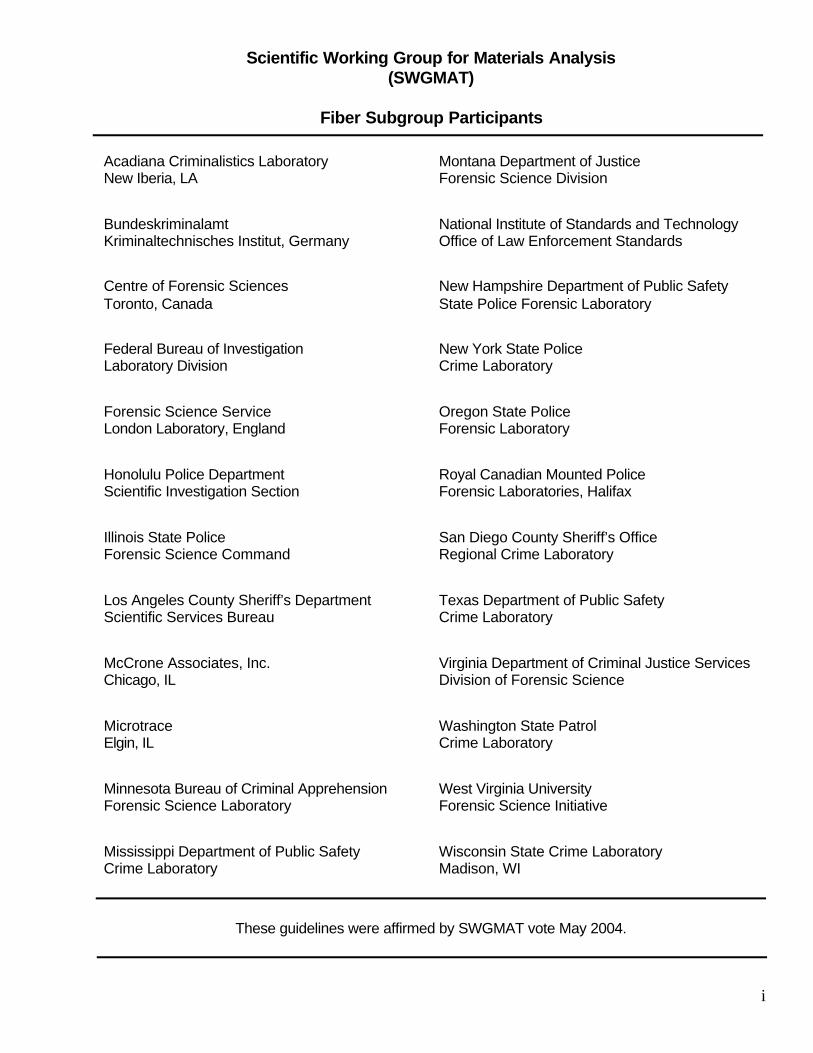
Scientific Working Group for Materials Analysis(SWGMAT)
Fiber Subgroup Participants
Acadiana Criminalistics Laboratory New Iberia, LA
Montana Department of Justice Forensic Science Division
Bundeskriminalamt Kriminaltechnisches Institut, Germany
National Institute of Standards and TechnologyOffice of Law Enforcement Standards
Centre of Forensic SciencesToronto, Canada
New Hampshire Department of Public SafetyState Police Forensic Laboratory
Federal Bureau of InvestigationLaboratory Division
New York State Police Crime Laboratory
Forensic Science ServiceLondon Laboratory, England
Oregon State PoliceForensic Laboratory
Honolulu Police Department Scientific Investigation Section
Royal Canadian Mounted PoliceForensic Laboratories, Halifax
Illinois State PoliceForensic Science Command
San Diego County Sheriff’s OfficeRegional Crime Laboratory
Los Angeles County Sheriff’s DepartmentScientific Services Bureau
Texas Department of Public SafetyCrime Laboratory
McCrone Associates, Inc.Chicago, IL
Virginia Department of Criminal Justice ServicesDivision of Forensic Science
MicrotraceElgin, IL
Washington State Patrol Crime Laboratory
Minnesota Bureau of Criminal ApprehensionForensic Science Laboratory
West Virginia UniversityForensic Science Initiative
Mississippi Department of Public SafetyCrime Laboratory
Wisconsin State Crime Laboratory Madison, WI
These guidelines were affirmed by SWGMAT vote May 2004.
Page 2 of 66
A FORENSIC FIBER EXAMINER TRAINING PROGRAM
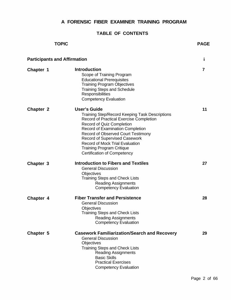
TABLE OF CONTENTS
TOPIC PAGE
Participants and Affirmation i
Chapter 1 Introduction 7Scope of Training Program Educational PrerequisitesTraining Program ObjectivesTraining Steps and ScheduleResponsibilitiesCompetency Evaluation
Chapter 2 User’s Guide 11Training Step/Record Keeping Task Descriptions Record of Practical Exercise CompletionRecord of Quiz CompletionRecord of Examination CompletionRecord of Observed Court Testimony Record of Supervised CaseworkRecord of Mock Trial Evaluation Training Program Critique Certification of Competency
Chapter 3 Introduction to Fibers and Textiles 27General DiscussionObjectivesTraining Steps and Check Lists
Reading AssignmentsCompetency Evaluation
Chapter 4 Fiber Transfer and Persistence 28General DiscussionObjectivesTraining Steps and Check Lists
Reading AssignmentsCompetency Evaluation
Chapter 5 Casework Familiarization/Search and Recovery 29General DiscussionObjectivesTraining Steps and Check Lists
Reading AssignmentsBasic SkillsPractical ExercisesCompetency Evaluation
Page 3 of 66
TOPIC PAGE
Chapter 6 Microscopy Review 33General DiscussionObjectivesTraining Steps and Check Lists
Reading AssignmentsBasic SkillsPractical ExercisesCompetency Evaluation
Practical Examination A
Chapter 7 Fiber Examinations/Preliminary Observations 35General DiscussionObjectivesTraining Steps and Check Lists
Reading AssignmentsBasic SkillsPractical ExercisesCompetency Evaluation
Chapter 8 Identification of Vegetable Fibers 37General DiscussionObjectivesTraining Steps and Check Lists
Reading AssignmentsBasic SkillsPractical ExercisesCompetency Evaluation
Chapter 9 Identification of Animal Textile Fibers 39General DiscussionObjectivesTraining Steps and Check Lists
Reading AssignmentsBasic SkillsPractical ExercisesCompetency Evaluation
Chapter 10 Identification of Inorganic Fibers 41General DiscussionObjectivesTraining Steps and Check Lists
Reading AssignmentsBasic SkillsPractical ExerciseCompetency Evaluation
Page 4 of 66
TOPIC PAGE
Chapter 11 Manufactured Fiber Examination - Optical Properties 43General DiscussionObjectivesTraining Steps and Check Lists
Reading AssignmentsBasic SkillsPractical ExercisesCompetency Evaluation
Chapter 12 Manufactured Fiber Examination - Cross Sections 45General DiscussionObjectivesTraining Steps and Check Lists
Reading AssignmentsBasic SkillsPractical ExercisesCompetency Evaluation
Chapter 13 Manufactured Fiber Examination - Solubility 47General DiscussionObjectivesTraining Steps and Check Lists
Reading AssignmentsBasic SkillsPractical ExercisesCompetency Evaluation
Chapter 14 Manufactured Fiber Examination - Thermal Microscopy 48General DiscussionObjectivesTraining Steps and Check Lists
Reading AssignmentsBasic SkillsPractical ExercisesCompetency Evaluation
Practical Examination B
Chapter 15 Manufactured Fiber Examination - Infrared Spectroscopy 50General DiscussionObjectivesTraining Steps and Check Lists
Reading AssignmentsBasic SkillsPractical ExercisesCompetency Evaluation
Page 5 of 66
TOPIC PAGE
Chapter 16 Fiber Examination - Comparison Microscopy 52General DiscussionObjectivesTraining Steps and Check Lists
Reading AssignmentsBasic SkillsPractical ExercisesCompetency Evaluation
Practical Examination C
Chapter 17 Fiber Examination - Fluorescence Microscopy 54General DiscussionObjectivesTraining Steps and Check Lists
Reading AssignmentsBasic SkillsPractical ExercisesCompetency Evaluation
Chapter 18 Fiber Examination - UV/VIS Microspectrophotometry 56General DiscussionObjectivesTraining Steps and Check Lists
Reading AssignmentsBasic SkillsPractical ExercisesCompetency Evaluation
Chapter 19 Fiber Examination - Dye Analysis/TLC 58General DiscussionObjectivesTraining Steps and Check Lists
Reading AssignmentsBasic SkillsPractical ExercisesCompetency Evaluation
Practical Examination D
Chapter 20 Fiber Examination - Other Techniques 60General DiscussionObjectivesTraining Steps and Check Lists
Reading AssignmentsCompetency Evaluation
Page 6 of 66
TOPIC PAGE
Chapter 21 Textile Examinations 61General DiscussionObjectivesTraining Steps and Check Lists
Reading AssignmentsBasic SkillsPractical ExercisesCompetency Evaluation
Chapter 22 Cordage Examinations 63General DiscussionObjectivesTraining Steps and Check Lists
Reading AssignmentsBasic SkillsPractical ExercisesCompetency Evaluation
Practical Examination E
Chapter 23 Interpretation and Presentation 65General DiscussionObjectivesTraining Steps and Check List
Reading AssignmentsInterpretive ExercisesCompetency Evaluation
Supervised Casework Mock Trial CourtWritten Examination
Appendix I Reading Assignments (pages 1 - 24)
Appendix II Practical Exercises (pages 1 - 128)
Page 7 of 66
Chapter 1 Introduction
Scope of Training Program
1. This training program manual is intended as a trainer’s and trainee’s guide through the training process. Itcontains pertinent assignments and exercises to be distributed to the trainee as required. Literature andsources of information other than those listed should also be considered. As time and monetary resourcespermit, trainees should be provided with appropriate additional training experiences such as off-site academiccourses and exposure to industrial manufacturing and analysis of materials.
This manual is designed in a modular format to be used as the basis for individual lesson plans, studentorientation, training program monitoring and evaluation. It may also be used to record the trainee’s progress,and prepare the trainee for assigned projects and examinations.
2. It is the intent of the training program to provide a foundation of theoretical knowledge and basic practicalskills for a trainee to become a fully qualified analyst capable of making appropriate analytical decisions,competent examinations, and proper interpretations of the analytical results. The modules cover the topics thatshould be included in a forensic fiber examiner training program. In some instances, modules or topics mayinclude methods and techniques, or alternative methods and techniques which are not currently employed inthe laboratory, or which may be considered antiquated. For those instances, while the trainee may not gainpractical skills, the trainee is expected to gain the theoretical knowledge about the alternative methods, theirlimitations, and/or their appropriate application.
3. Considering the overall possibilities, fibrous trace evidence may originate from many sources (e.g. textiles,cordage, building materials). Several fiber classification schemes exist that are utilized by forensic scientists,based largely on fiber production methods and end uses. It is imperative that the trainee and trainer understandthe scope and organization of this training program before commencing. The orientation and the emphasis ofthis training program is on fibers as used in textiles and textile products. This training program utilizes thegeneral classification scheme of natural versus manufactured fibers, and is further organized around theconcepts of how fibers and textiles are identified and compared.
Educational Requirements
The minimum academic level for a fiber trainee is a BA/BS degree in a natural or applied science.
Trainees are expected to have a good theoretical background in pertinent subjects and have successfullycompleted the following undergraduate or graduate courses:
A. one year (or equivalent) of General Chemistry with laboratory,B. one year (or equivalent) of Organic Chemistry with laboratory, and C. General Biology with laboratory.
If the following is not available at the undergraduate or graduate level, then completion throughstructured course work is required:
A. analytical/instrumental analysis,B. basic microscopy and polarized light microscopy, andC. fiber microscopy.

Page 8 of 66
Training Program Objectives
Through completion of this training, the trainee is expected to build on his/her formal educational backgroundand gain theoretical knowledge and practical skills in the following areas:
1. equipment and instrumentation use, routine maintenance, and functionality assessment;2. fiber and textile history, terminology, and usage including common end uses of different fiber, yarn,
fabric and cordage types;3. fiber and textile chemistry and manufacturing processes including chemical compositions, chemical
and mechanical treatments, and manufacturing mechanical, dyeing and finishing processes;4. search, recovery, preservation, and examination techniques including proper sample handling;
packaging and documention for fibrous materials associated with a variety of substrates;5. classification of natural and manufactured fibers used in textile materials;6. identification and/or comparison of natural and manufactured fibers by optical, chemical and
physical property examinations;7. examination and comparison of textiles for physical matches, physical construction, and fiber
composition; 8. fiber and textile physical wear, damage, and manufacturing artifacts assessment;9. accessing relevant literature and standards databases;
10. fiber and textile examination, identification and/or comparison results interpretations includingfactors affecting the analytical interpretation and the significance of the evidence with respect to fibertransfer and persistence;
11. proper laboratory report completion and testimonial evidence presentation; and 12. detection and assessment of other types of physical evidence which may be encountered during
fiber and textile examinations.
Training Steps and Schedule
1. With the aid of this manual, the trainee should gain theoretical knowledge and practical skills through the following methods:
A. readingB. personal instruction
1. lectures and discussions2. practical demonstration of basic skills
C. practical skills1. basic skills2. practical exercises3. assisting in and performing supervised casework
D. observing others 1. in casework2. in court
E. examinations1. oral and/or written quizzes2. practical examinations3. written examinations4. mock trial
2. The expected training period will be a minimum of 12 months, full time, for the inexperienced traineewith no prior forensic experience, and will include casework observation, supervised caseworkexaminations and mock trial. Flexibility in the duration of the expected training period may take intoaccount the trainee’s academic background, experience, and aptitude. A written schedule of expectedcompletion dates for training goals shall be determined and provided to the trainee.

Page 9 of 66
Responsibilities
It is the responsibility of each agency/laboratory to define “satisfactory completion” whenever used in thistraining program. Each trainee shall be assigned a trainer. The assigned trainer may not necessarily be thesupervisor of the Section/Unit, but must be a technically competent fiber examiner, internal or external to theagency.
The trainer shall be responsible for:1. introducing the trainee to the relevant technical literature, procedures, training material, and
reference or standards collections; to include the agency’s standard operating procedures;2. assisting the trainee in interpretation of the literature by discussion of technical methods and
foundational theory; 3. providing training in the performance of some basic practical skills and methods, and coordinating
training in other methods with other experienced analysts; 4. providing instruction in case management, including but not limited to,
a. chain of custody documentationb. evidence processing, preservation and storagec. decision making criteria, data interpretation and conclusionary statementsd. documentation of analysese. report writingf. laboratory safety practices
5. providing an example of ethical and proper professional conduct and communications;6. providing instruction on appropriate quality assurance and quality control procedures;7. providing instruction on proper court presentation and etiquette; and8. providing a written schedule of expected completion dates for training goals.
The trainer and supervisor shall be responsible for monitoring the trainee’s progress, and the thoroughness and correctness of the trainee’s education. All qualified members of the laboratory are expected to makethemselves available to the trainee for discussion of training topics.
The trainee shall be responsible for:1. meeting the training objectives within the specified training schedule;2. self-study of the relevant technical literature;3. practicing basic skills, analytical methods and techniques on non-case samples;4. completing the practical exercises;5. observing casework;6. satisfactory completion of sponsored course work or its equivalent; and7. performing casework under supervision.
Competency Evaluations
The trainee should be continuously evaluated throughout the training for comprehension and competency intheoretical knowledge, basic practical skills and critical thinking skills. Training is progressive and continuouslybuilds on and reinforces prior learning. Deficiencies on any of the training steps may occur during the course ofthe training and should be rectified. It is important that these deficiencies be openly and promptly discussedamong the trainee, trainer and supervisor, as appropriate. Repeating training steps and testing may benecessary to satisfactorily complete this training program.
It is imperative that competency testing, of any type indicated below, be prepared and evaluated by the trainerand/or other technically qualified staff members to ensure the relevancy of questions, as well as thecorrectness, thoroughness and directness of answers.

Page 10 of 66
The trainer shall discuss the training progress with the trainee and supervisor on a regular basis. Thesupervisor and trainer shall evaluate training and competency of a trainee by way of:
1. oral and/or written quizzes,2. written examinations,3. practical examination of unknowns,4. supervised casework, and 5. mock trial
Documentation of all of the trainee’s tests shall be in written form and retained in the laboratory’s files.

Page 11 of 66
Chapter 2 User’s Guide
Training Steps and Record Keeping Task Descriptions
The Table of Contents preceding the Introduction outlines the segments of the training program manual byChapter and Section. Amendments to this manual may be issued periodically or may be developed and issuedby a laboratory in order to meet their specific needs. Each laboratory’s procedures or methods manuals maybe incorporated into this training program. It is the responsibility of each laboratory to maintain a currenttraining program manual, record of amendments, and record of additional requirements beyond thoserecommended by this program.
Each Chapter is divided into sections including:1. General Discussion - a general module subject description including a statement of the intended
scope of topic coverage2. Objectives - defined learning results3. Training Steps and Teaching Point Check List
a. reading assignmentsb. basic skills tablec. practical exercises
4. Competency Testing - guide for the topical area in the form of suggested application of quizzes, writtenexaminations, and/or practical examinations
During the training period, the trainer shall:1. ensure that reading assignments material, supplies and equipment for practical exercises are available;2. provide personal instruction, discussion and practical demonstrations as necessary;3. monitor the trainee’s check sheets to ensure adequate progress is being made and documented, and
schedule expected completion dates;4. ensure that the trainee adequately reviews previous chapter and section material to reinforce topics,
introduce new perspectives to topics, and adequately integrate topics that were studied separately;5. be available to answer trainee questions;6. critically evaluate when a trainee can satisfactorily perform each of the basic skills;7. review and critically discuss completed practical exercises, then initial the appropriate space on the list
when satisfactorily completed;8. prepare, administer and grade oral/written quizzes, written examinations and practical examinations,
discuss the examination results with the trainee and rectify any deficiencies;9. keep management informed of the trainee’s progress; and
10. communicate the agency’s policy on the requirements for satisfactory completion of the training modules.
During the training period, the trainee shall:1. complete all required reading assignments and take notes as appropriate;2. carefully observe all demonstrated practical basic skills;3. practice the basic skills until they are competent in the skill;4. perform the practical exercises and make appropriate notes on such;5. satisfactorily complete oral and written examinations, discussing and correcting any deficiencies; and6. provide a critical evaluation of the training program.
Page 12 of 66
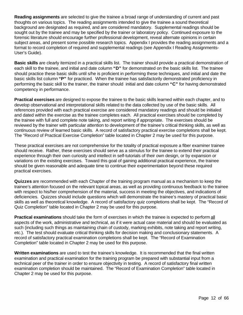
Reading assignments are selected to give the trainee a broad range of understanding of current and pastthoughts on various topics. The reading assignments intended to give the trainee a sound theoreticalbackground are designated as required, and are considered mandatory. Supplemental readings should besought out by the trainee and may be specified by the trainer or laboratory policy. Continued exposure to theforensic literature should encourage further professional development, reveal alternate opinions in certainsubject areas, and present some possible research topics. Appendix I provides the reading assignments and aformat to record completion of required and supplemental readings (see Appendix I Reading Assignments-User’s Guide).
Basic skills are clearly itemized in a practical skills list. The trainer should provide a practical demonstration ofeach skill to the trainee, and initial and date column “D” for demonstrated on the basic skills list. The traineeshould practice these basic skills until s/he is proficient in performing these techniques, and initial and date thebasic skills list column “P” for practiced. When the trainee has satisfactorily demonstrated proficiency inperforming the basic skill to the trainer, the trainer should initial and date column “C” for having demonstratedcompetency in performance.
Practical exercises are designed to expose the trainee to the basic skills learned within each chapter, and todevelop observational and interpretational skills related to the data collected by use of the basic skills. Allreferences provided with each practical exercise are considered mandatory readings and should be initialedand dated within the exercise as the trainee completes each. All practical exercises should be completed bythe trainee with full and complete note taking, and report writing if appropriate. The exercises should bereviewed by the trainer with particular attention to development of the trainee’s critical thinking skills, as well ascontinuous review of learned basic skills. A record of satisfactory practical exercise completions shall be kept.The “Record of Practical Exercise Completion” table located in Chapter 2 may be used for this purpose.
These practical exercises are not comprehensive for the totality of practical exposure a fiber examiner traineeshould receive. Rather, these exercises should serve as a stimulus for the trainee to extend their practicalexperience through their own curiosity and intellect in self-tutorials of their own design, or by expansion orvariations on the existing exercises. Toward this goal of gaining additional practical experience, the traineeshould be given reasonable and adequate time to continue their experimentation beyond these requiredpractical exercises.
Quizzes are recommended with each Chapter of the training program manual as a mechanism to keep thetrainee’s attention focused on the relevant topical areas, as well as providing continuous feedback to the traineewith respect to his/her comprehension of the material, success in meeting the objectives, and indications ofdeficiencies. Quizzes should include questions which will demonstrate the trainee’s mastery of practical basicskills as well as theoretical knowledge. A record of satisfactory quiz completions shall be kept. The “Record ofQuiz Completion” table located in Chapter 2 may be used for this purpose.
Practical examinations should take the form of exercises in which the trainee is expected to perform allaspects of the work, administrative and technical, as if it were actual case material and should be evaluated assuch (including such things as maintaining chain of custody, marking exhibits, note taking and report writing,etc.). The test should evaluate critical thinking skills for decision making and conclusionary statements. Arecord of satisfactory practical examination completions shall be kept. The “Record of ExaminationCompletion” table located in Chapter 2 may be used for this purpose.
Written examinations are used to test the trainee’s knowledge. It is recommended that the final writtenexamination and practical examination for the training program be prepared with substantial input from atechnical peer of the trainer in order to ensure objectivity in testing. A record of satisfactory final writtenexamination completion should be maintained. The “Record of Examination Completion” table located in Chapter 2 may be used for this purpose.
Page 13 of 66
Court testimony observation is a valuable learning tool for the trainee. The trainee should attempt to observea variety of examiners testify on a range of offenses and types of examinations. The number and frequency ofsuch observations will be dictated by circumstances and the trainer’s judgement. The testimony should bediscussed with the trainee after each observation. A record of the observed court testimony shall be kept. Recommended points of observation and discussion, and a “Record of Observed Court Testimony” formlocated in Chapter 2 may be used for this purpose. The trainer should consider using review of trial transcriptsto supplement court testimony observations when an adequate number of trial observations are logisticallydifficult in your laboratory’s circumstances (e.g. testimony is too infrequent or excessive distances).
Supervised casework and assisting in casework is expected throughout the training period. Initially, thetrainee will observe other members of the laboratory who are working relevant cases. As training progresses,the trainee may be asked to assist others in their casework. It is expected that the levels of responsibility andassistance will be increased until the trainee is able to perform supervised casework, and complete casesindependently by the end of the training period. A record of supervised casework shall be kept. The “Record ofSupervised Casework” form located in Chapter 2 may be used for this purpose.
If laboratory policy does not permit trainees to assist in casework prior to performing supervised casework, then the trainer should expose the trainee to this facet of training by inserting simulated casework practical exercises designed to develop reasoning skills, analytical performance and responsibility.
Mock trials should be held using separate individuals for the various roles, and using simulated caseworkmaterial analyzed and interpreted by the trainee. Satisfactory completion of the mock trial should be byconcurrence of all participants, including the trainee. Some suggested evaluation points are provided on the“Record of Mock Trial Evaluation” form located in Chapter 2. A written record of satisfactory completion of themock trial shall be kept and the Mock Trial Evaluation Form may be used for this purpose.
Final competency evaluation for satisfactory completion of the training program shall be in written form andmaintained in the laboratory files. The Certification of Competency form located in Chapter 2 may be used forthis purpose.

Page 14 of 66
RECORD OF PRACTICAL EXERCISE COMPLETION
Name of Trainee: Date training commenced:
Name of Trainer:
Name of Supervisor:
Chapt Satisfactory Practical Exercise Completion Trainee Initialsand Date
Trainer Initialsand Date
5 5-1 Fiber Transfer and Persistence
5-2 Collecting Fibers on Tape
6 6-1 Familiarization with the Stereomicroscope
6-2 Familiarization with the Compound Light Microscope
6-3 Familiarization with the Polarized Light Microscope
7 7-1 Fiber Manipulations
7-2 Observing Effects of Mounting Media
7-3 Observing Fiber Shape, Surface and Internal Structure
7-4 Observing Color and Pleochroism
7-5 Distinguishing Natural and Manufactured Fiber Classes
8 8-1 Microscopy of Non-woody Vegetable Fibers
8-2 Determining Natural Fiber Twist
9 9-1 Examining the Cuticle of Animal Hairs
9-2 Introduction to Examining Fibers of Animal Origin
10 10-1 Identification of Asbestos Fibers
11 11-1 Determining the Sign of Elongation
11-2 Measuring Birefringence
11-3 Measuring Refractive Indices by the Immersion Method
12 12-1 Cross-sectioning and Interpretation of Cross Sections
12-2 Determining the Modification Ratio
13 13-1 Solubility Testing of Acetate and Triacetate Fibers
14 14-1 Thermal Microscopy - Use of a Hot Stage
(Continued on next page)
Page 15 of 66
Chapt Satisfactory Practical Exercise Completion Trainee Initialsand Date
Trainer Initialsand Date
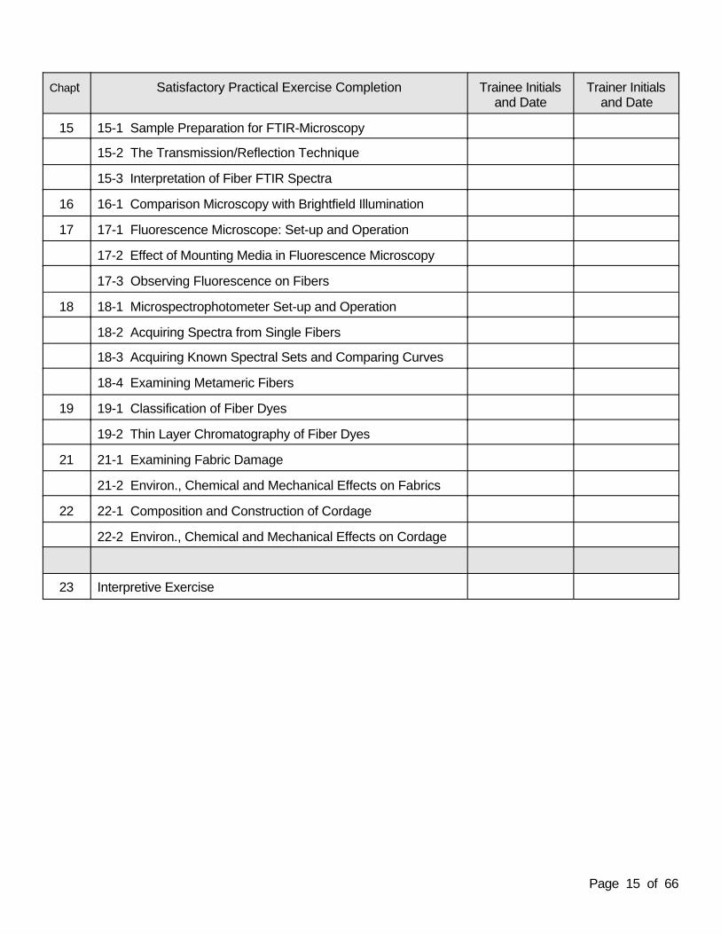
15 15-1 Sample Preparation for FTIR-Microscopy
15-2 The Transmission/Reflection Technique
15-3 Interpretation of Fiber FTIR Spectra
16 16-1 Comparison Microscopy with Brightfield Illumination
17 17-1 Fluorescence Microscope: Set-up and Operation
17-2 Effect of Mounting Media in Fluorescence Microscopy
17-3 Observing Fluorescence on Fibers
18 18-1 Microspectrophotometer Set-up and Operation
18-2 Acquiring Spectra from Single Fibers
18-3 Acquiring Known Spectral Sets and Comparing Curves
18-4 Examining Metameric Fibers
19 19-1 Classification of Fiber Dyes
19-2 Thin Layer Chromatography of Fiber Dyes
21 21-1 Examining Fabric Damage
21-2 Environ., Chemical and Mechanical Effects on Fabrics
22 22-1 Composition and Construction of Cordage
22-2 Environ., Chemical and Mechanical Effects on Cordage
23 Interpretive Exercise

Page 16 of 66
RECORD OF QUIZ COMPLETION
Name of Trainee: Date training commenced:
Name of Trainer:
Name of Supervisor:
Satisfactory Quiz Completionby Chapter
Trainee Initials and Date Trainer Initials and Date
3
4
5
6
7
8
9
10
11
12
13
14
15
16
17
18
19
20
21
22

Page 17 of 66
RECORD OF EXAMINATION COMPLETION
Name of Trainee: Date training commenced:
Name of Trainer:
Name of Supervisor:
Satisfactory Examination Completion Trainee Initials and Date Trainer Initials and Date
Practical Examination A Evidence Recovery (at end of Chapter 6)
Practical Examination B Fiber Identification (at end of Chapter 14)
Practical Examination C Fiber Identification and Comparison (at end of Chapter 16)
Practical Examination D Fiber Identification and Comparison (at end of Chapter 19)
Practical Examination E Textile and Cordage Examinations (at end of Chapter 22)
Final Written Examination (at end of Chapter 23)

Page 18 of 66
RECORD OF OBSERVED COURT TESTIMONY
Name of Trainee: Date training commenced:
Name of Trainer:
Name of Supervisor:
The trainee should discuss the salient points of providing court testimony such as:
1. What did you learn about legal proceedings?
2. What questions were asked by the prosecutor?
3. What questions were asked by the defense attorney?
4. Were there redirect questions and, if so, what were they?
5. What were the salient points of the testimony?

Page 19 of 66
RECORD OF SUPERVISED CASEWORK
I have observed and evaluated in the management and analysis of (Name of trainee)
casework from case .
S/he competently performed all duties of a fiber examiner throughout this casework. (signed and dated by evaluator).
or
S/he displayed some inadequacies in the management and analysis of this casework. I recommend that therebe remedial training in the area(s) of: (signed and dated by evaluator).
Page 20 of 66
RECORD OF SUPERVISED CASEWORK
I have observed and evaluated in the management and analysis of (Name of trainee)
casework from case .
S/he competently performed all duties of a fiber examiner throughout this casework. (signed and dated by evaluator).
or
S/he displayed some inadequacies in the management and analysis of this casework. I recommend that therebe remedial training in the area(s) of: (signed and dated by evaluator).
I have observed and evaluated in the management and analysis of (Name of trainee)
casework from case .
S/he competently performed all duties of a fiber examiner throughout this casework. (signed and dated by evaluator).
or
S/he displayed some inadequacies in the management and analysis of this casework. I recommend that therebe remedial training in the area(s) of: (signed and dated by evaluator).
I have observed and evaluated in the management and analysis of (Name of trainee)
casework from case .
S/he competently performed all duties of a fiber examiner throughout this casework. (signed and dated by evaluator).
or
S/he displayed some inadequacies in the management and analysis of this casework. I recommend that therebe remedial training in the area(s) of: (signed and dated by evaluator).

Page 21 of 66
RECORD OF MOCK TRIAL EVALUATION
Name of Trainee: Date Held:
Other Participants:
Suggested evaluation points include:
1. Was the witness able to clearly state his/her qualifications?
2. Was the witness prepared for testimony?
3. Was the testimony clear and explicit?
A. -at the lay juror level?
B. -at the expert technical level?
C. Were the limitations/significance of the evidence properly explained?
4. How was the witness’s demeanor and appearance?
5. Any suggested points of improvement?
Date and participant signatures upon satisfactory completion:

Page 22 of 66
TRAINING PROGRAM CRITIQUE
Name of Trainee: Date training commenced:
Name of Trainer: Date training completed:
Name of Supervisor:
Part I: Circle the letter of the response which most closely fits your impression.
A. Personal Instruction 1. The amount of personal instruction received from your supervisor/trainer and others in the section was:
(a) about right (b) too little (c) too much 2. The quality of personal instruction received from your supervisor/trainer and others in the section was:
(a) very good (b) adequate (c) poor
B. Reading Assignments 1. The number of papers included in the reading assignments was:
(a) about right (b) too few (c) too many
2. In general, I thought that the reading assignments were:(a) excellent (b) adequate (c) irrelevant
C. Practical Exercises
1. The number of practical exercises was:(a) about right (b) too few (c) too many
2. In general, I thought that the practical exercises were:(a) excellent (b) adequate (c) irrelevant
D. External Resources 1. The number of external resource people and materials used was:
(a) about right (b) too few (c) too many
2. The external resource materials were:(a) excellent (b) adequate (c) irrelevant
3. Specify external resource people or materials that were particularly noteworthy, good or bad:

Page 23 of 66
E. Audio/visual Materials
1. The audio/visual materials used were:(a) excellent (b) adequate (c) irrelevant
2. Specify audio/visual materials that were particularly noteworthy, good or bad:
F. In-house Discussions
1. The frequency of in-house discussions and round-tables was:(a) about right (b) too few (c) too many
2. The in-house discussions and round-tables were:(a) excellent (b) adequate (c) irrelevant
G. Practical Examinations
1. The number of practical examinations was:(a) about right (b) too few (c) too many
2. The level of complexity of the practical examinations was:(a) about right (b) too easy (c) too difficult
3. In general, I thought that the practical examinations were:(a) valuable (b) irrelevant
H. Quizzes/Written Examinations
1. The number of quizzes/written examinations was:(a) about right (b) too few (c) too many
2. The level of complexity of the quizzes/written examinations was:(a) about right (b) too easy (c) too difficult
3. In general, I thought that the quizzes/written examinations were:(a) relevant (b) irrelevant
I. Mock Trial(s)
1. The number of mock trials was:(a) about right (b) too few (c) too many
2. The level of complexity of the mock trials was:(a) about right (b) too easy (c) too difficult
3. In general, I thought that the mock trials were:(a) valuable (b) irrelevant

Page 24 of 66
J. General
1. The length of training was:(a) about right (b) too short (c) too long
2. The coverage of the material was:(a) good (b) adequate (c) deficient in areas
3. In general, I thought that this training program was:(a) good (b) adequate (c) needs improvement
Part II: Use the back of this sheet or additional pages if necessary.
A. Reading Assignments 1. The following reading assignments, if any, were particularly good:
2. The following reading assignments, if any, should be deleted:
3. The following reading assignments or papers, if any, should be added:
B. General 1. The coverage of the following topics or areas, if any, should be expanded:
2. The coverage of the following topics or areas, if any, should be reduced:
3. Additional comments by trainee:

Page 25 of 66
Part III Comments by the trainer and supervisor:
1. Indicate any areas in Part I or II where you strongly agree or disagree with the trainee.
2. Make any additional, general comments on the training program.
Signature of Trainee:
Signature of Trainer:
Signature of Supervisor:
Date of Training Program :

Page 26 of 66
CERTIFICATION OF COMPETENCY
I have reviewed the training records, skills inventory, practical exercises, examinations, supervised casework,
and court presentation skills, and have discussed the final assessment of competence for fiber and textile
examinations with the trainee and trainer . (Name) (Name)
is approved to independently conduct fiber and textile examinations. (Name)
_____________________________________________________________ Supervisor Date
Page 27 of 66
Chapter 3 Introduction to Fibers and Textiles
General Discussion
This training module will introduce the trainee to the basic concepts and theoretical knowledge of fiber andtextile product manufacture and use, commercial and forensic classifications, and an overview of forensicexaminations for identification and comparisons. It is intended to be historical as well as contemporary, and toprovide the theoretical foundation upon which practical analytical skills will be built in the subsequent modules.
Objectives
Through completion of this module the trainee will develop the theoretical knowledge to be conversant in:1. fiber and textile history, usage and manufacturing,2. fiber and textile technology and terminology,3. chemistry and manufacturing processes of fibers and dyes,4. fiber classification schemes, and5. identification vs. comparison of fibers and textiles.
Training Steps and Check List
1. Reading Assignments: Complete Chapter 3 reading assignments listed in Appendix I.
2. Additional training may be obtained from textile museum or industrial manufacturing plant tours, videotapesof textile processing, visits to fabric and carpet stores, etc. A record of additional training resources used (e.g.tours, museums) should be noted and maintained.
Competency Evaluation
The trainee shall be evaluated by quizzes on theoretical knowledge as specified in the module objectives todemonstrate comprehension of the reading assignments. The quizzes should include any questions which willdemonstrate theoretical or practical knowledge acquired through additional training means such as industrialand museum tours.
Page 28 of 66
Chapter 4 Fiber Transfer and Persistence
General Discussion
This training module will introduce the trainee to the basic concepts and theoretical knowledge of fiber transferand persistence from two perspectives. First, it is transfer and persistence that imparts a value to textile fibersas associative trace evidence. Second, it is transfer and persistence that can result in fibrous evidencecontamination and loss. It is intended that the trainee demonstrate a sound theoretical foundation of thecontamination and loss concepts before exposure to actual evidentiary materials and practical basic skills.
Objectives
Through completion of this module the trainee will develop the theoretical knowledge to be conversant in:1. Locard’s Exchange Principle;2. the potential significance of fibers as associative trace evidence in forensic cases;3. textile fiber sheddability;4. fiber transfer mechanisms and factors affecting transfer; 5. fiber persistence mechanisms and factors influencing persistence, and 6. techniques utilized to prevent or reduce fibrous evidence contamination and loss from the time of field examinations through laboratory analyses including:
a. limiting contacts between items and individuals,b. wearing appropriate protective apparel, c. proper packaging, handling and labeling, d. cleaning equipment and work surfaces, e. maintaining controlled environments,f. separation of evidence from different sources by location and/or time.
Training Steps and Check List
1. Reading Assignments: Complete Chapter 4 reading assignments listed in Appendix I.
Competency Evaluation
The trainee shall be evaluated by quizzes on theoretical knowledge as specified in the module objectives todemonstrate comprehension of the reading assignments.

Page 29 of 66
Chapter 5 Casework Familiarization/Search and Recovery
General Discussion
This training module serves as a guide for introducing the basic procedures and techniques for properdocumentation, detection, collection and preservation of fibrous and other trace evidence from crime scenes,individuals and items submitted to the laboratory for examination. The trainee should be exposed to a wide variety of casework throughout the training period. This exposure will include the trainee’s assistance in exhibitsearching, observation of subsequent analyses, discussion of data generated, results obtained, andconclusions drawn. This module should be completed in conjunction with Chapter 6 Microscopy Review for proper operation of stereomicroscopes.
The trainee should become proficient with the format and procedures pertaining to casework administrative andtechnical documentation, and report writing as outlined in the laboratory’s procedures manual.
Objectives
Upon satisfactory completion of this training module, the trainee will have acquired introductory theoretical andpractical knowledge of:
1. the significance and use of trace physical evidence from the scientific perspective, and an overview ofthe types of information one may obtain from analyzing different types of trace evidence;
2. general evidence detection, collection and preservation techniques;3. guidelines for evaluating, prioritizing and coordinating processing of items for multiple types of evidence
from the administrative and scientific perspectives;4. the administrative, legal and scientific requirements for case documentation and reporting;5. evidence security requirements and practices;6. health and safety requirements and practices; and7. quality assurance requirements and practices.
Upon satisfactory completion of this training module, the trainee will have developed and demonstratedtheoretical knowledge and practical skills to:
1. search, recover, and preserve fibrous evidence from a variety of substrates;2. prevent contamination and loss of evidence during search and recovery;3. document searches and recoveries; and4. provide testimony on the learned practical skills.
Training Steps and Check Lists
1. Reading Assignments: Complete Chapter 5 reading assignments listed in Appendix I.
2. Observe casework in progress to include examination of case documentation and final reports. Discusswork in progress with the examiner regarding decision making criteria in case processing and reporting. Thetrainee and examiner should use the following topical outline as a reference for discussion:
1. significance and usea. integrity of evidenceb. other forms of trace evidence

Page 30 of 66
2. documentation a. case file documentation per laboratory policy to include notes containing: date, initials, item
description, unique identifier, sketches, measurements and imagesb. chain of custodyc. labeling items and packagesd. record maintenance, storage and security
3. contamination and loss practicesa. limiting contact between items and individualsb. appropriate protective apparelc. limiting evidence handling and exposure to contaminantsd. collecting, packaging and sealing in appropriate packaginge. controlled environmentsf. clean equipment and work surfacesg. separation of evidence from different sources by location and/or timeh. documenting any situation which could have contaminated or compromised the evidencei. consideration of associated evidentiary items from other disciplines
4. detection, collection and preservation techniquesa. criteria for selection of technique and processing sequence b. recording techniques c. visual searches, with or without magnification, to include oblique lighting and alternate light
sourcesd. using the most direct and least intrusive collection methods: picking, tape lifting, scraping,
vacuuming, combing and cuttinge. appropriate packaging for wet items, use of temporary packages, and proper packaging
material 5. questioned versus known samples, and collection of representative known samples6. laboratory analyses
a. identificationb. comparisonc. sourcesd. destructive versus non-destructive testinge. documentation including notes, sketches and imagesf. maintaining evidence integrity and security
7. health and safety in laboratory and non-laboratory settingsa. mechanical hazardsb. chemical hazardsc. biological hazards
8. crime scene/field evidencea. site and item identificationb. observations and documentationc. searches/collectionsd. interpretationse. evidence disposition
9. laboratory examination report writinga. case identification b. items received and methods of analysis usedc. examination results and conclusions
10. court testimony 11. quality assurance/quality control of examinations, reports and testimony

Page 31 of 66
Trainee record of observed and discussed casework in progress (adequate number specified by trainer orlaboratory policy):
Case Identifier Date and Examiner Observed
1.
2.
3.
4.
5.
6.
3. Basic Skills
Basic Skills in Exhibit Searching D P C
1. contamination and loss prevention techniques when actually manipulating evidentiary items
2. visual searching, using alternate light sources
3. stereomicroscopical searching
4. fibrous evidence recovery by: a. picking b. tape lifting c. scraping d. vacuuming e. combing f. cutting
5. documenting and packaging
4. Practical Exercises: Complete these exercises located in Appendix II.
5-1 Fiber Transfer and Persistence5-2 Collecting Fibers on Tape

Page 32 of 66
Competency Evaluation
The trainee shall be evaluated by quizzes on theoretical knowledge and basic practical skills as specified in themodule objectives. The quizzes should include questions on the significance and use of trace evidence, andquestions that assess the trainee’s ability to properly reason through and perform general trace evidencedetection, collection, preservation, and documentation.

Page 33 of 66
Chapter 6 Microscopy Review
General Discussion
This module is intended as a guide to familiarize the trainee with the operating theory and care of microscopesused in the laboratory. Emphasis is placed on proper illumination, calibration and preliminary observationsmade with stereomicroscopes and polarized light microscopes (PLM), which are the instruments typically usedfirst in any fibrous evidence examinations.
Objectives
Upon satisfactory completion of this training module, the trainee will have developed and demonstratedtheoretical knowledge and/or practical skills to:
1. understand microscope optics;2. properly operate and maintain each microscope and its accessories including adjustments, cleaning
and diagnosing problems;3. establish proper microscope illumination including adjustment for Köhler illumination;4. calibrate the ocular micrometer, and acquire proper measurements utilizing ocular and stage
micrometers; and5. select appropriate microscopes and accessories for the observational task required.
Training Steps and Check Lists
1. Reading Assignments: Complete Chapter 6 reading assignments listed in Appendix I.
2. Basic Skills
Basic Skills in Microscopy: D P C
1. operating, adjusting and cleaning a microscope
2. centering stages and objectives
3. setting up Köhler illumination
4. measuring with ocular and stage micrometers
5. observing relative refractive index by Becke line
6. distinguishing isotropic and anisotropic substances
7. determining extinction positions
8. observing interference colors
9. taking photomicrographs
Page 34 of 66
3. Practical Exercises: Complete these exercises located in Appendix II.
6-1 Familiarization with the Stereomicroscope 6-2 Familiarization with the Compound Light Microscope
Part 1 Köhler IlluminationPart 2 Basic Micrometry and Calibrating an Ocular Micrometer
6-3 Familiarization with the Polarized Light MicroscopePart 1 Refractive Index by Becke Line ObservationsPart 2 Observation of Extinction Positions and Interference Colors in Crossed Polars
Competency Evaluation
The trainee shall be evaluated by quizzes on theoretical knowledge and basic practical skills as specified in themodule objectives. The quizzes should include practical skills questions such as measuring fiber dimensionsof length and diameter.
Practical Examination A: Trace Evidence Detection, Collection and Preservation
The trainee should be given simulated case materials to screen for trace evidence. This competency test is tobe general in nature and should not cover fiber examination analytical techniques. The trainee should have theskills to perform generalized trace evidence searches and collections upon satisfactory completion of thepractical examination.

Page 35 of 66
Chapter 7 Fiber Examinations/Preliminary Observations
General Discussion
This module is intended as a guide to familiarize the trainee with fibrous evidence handling and mountingtechniques. The trainee will be taught the proper visual and microscopical preliminary observations andexaminations to distinguish between natural and manufactured fibers as broad categories.
Objectives
Upon satisfactory completion of this training module, the trainee will have developed and demonstratedtheoretical knowledge and/or practical skills to:
1. select proper mounting media and tools for making these preliminary observations;2. properly handle fibrous evidence during recovery, mounting, examination, and de-mounting while
maintaining control and integrity of the items;3. discern fiber shape, surface features, internal structure, and color, and apply accepted terminology to
the features observed;4. classify fibers as manufactured, animal or vegetable based on preliminary observation of
the macroscopic and microscopic fiber features; and5. measure fiber diameter and observe color and pleochroism.
Training Steps and Check Lists
1. Reading Assignments: Complete Chapter 7 reading assignments listed in Appendix I.
2. Basic Skills
Basic Skills in preliminary fiber examinations: D P C
1. removing fibers from tape
2. mounting fibers for microscopical examination
3. qualitative bright field and PLM examinations
4. assessing color and pleochroism
5. assessing shape, surface and internal features by optical cross-sectioning
6. de-mounting and securing fibers
Page 36 of 66
3. Practical Exercises: Complete these exercises located in Appendix II.
7-1 Fiber Manipulations: Removing Fibers from Tape and Mounting7-2 Observing Effects of Mounting Media 7-3 Observing Fiber Shape, Surface and Internal Structure7-4 Observing Color and Pleochroism7-5 Distinguishing Natural and Manufactured Fiber Classes
Competency Evaluation
The trainee shall be evaluated by quizzes on theoretical knowledge and basic practical skills as specified in themodule objectives. The quizzes should include practical skills questions such as distinguishing natural frommanufactured fibers and vegetable and animal fibers, making qualitative PLM observations, etc.
Page 37 of 66
Chapter 8 Identification of Vegetable Fibers
General Discussion
This module is intended as a guide to familiarize the trainee with techniques utilized in the identification of theplant fibers which are commonly used in textile products and cordage (cotton, flax, ramie, jute, hemp, etc.). The scope of this module is not intended to include other botanical identifications. This module should bereviewed/reworked in conjunction with several other chapters of the training program manual in order to fullyintegrate all topics.
Objectives
Upon satisfactory completion of this training module, the trainee will have developed and demonstratedtheoretical knowledge and/or practical skills to:
1. use bright field and polarized light microscopy to identify plant tissue and cellular structural features thatallow for the classification of the fiber(s) as vegetable, and as bast (stem) fibers, leaf fibers, or seed(fruit) fibers;
2. determine the plant cell wall spiral thickening’s direction of twist and apply this information to a botanicalidentification;
3. make a botanical identification of the fiber source as specifically as possible using reference sources and comparisons; and
4. have an understanding of the processing, dyeing techniques, and end use products of the variousvegetable fibers.
Training Steps and Check Lists
1. Reading Assignments: Complete Chapter 8 reading assignments listed in Appendix I.
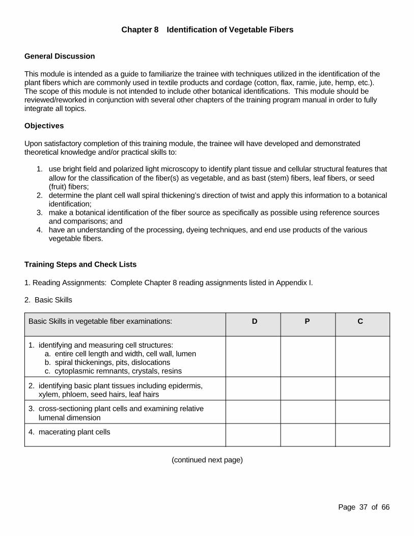
2. Basic Skills
Basic Skills in vegetable fiber examinations: D P C
1. identifying and measuring cell structures: a. entire cell length and width, cell wall, lumen b. spiral thickenings, pits, dislocations c. cytoplasmic remnants, crystals, resins
2. identifying basic plant tissues including epidermis, xylem, phloem, seed hairs, leaf hairs
3. cross-sectioning plant cells and examining relative lumenal dimension
4. macerating plant cells
(continued next page)

Page 38 of 66
Basic Skills in vegetable fiber examinations: D P C
5. determining sign of elongation and direction of twist with first order red plate/PLM
6. determining direction of twist with the drying twist test
7. microchemical testing for degree of lignification
8. ashing
3. Practical Exercises: Complete these exercises located in Appendix II.
8-1 Microscopy of Non-woody Vegetable Fibers8-2 Determining Natural Fiber Twist
Part 1 The Herzog EffectPart 2 The Drying Twist Test
(Note: these exercises should be completed in conjunction with or subsequent to learning the material presented in Chapter 11 and Chapter 12.)
Competency Evaluation
The trainee shall be evaluated by quizzes on theoretical knowledge and basic practical skills as specified in themodule objectives. The quizzes should include practical skills questions such as vegetable fiber identification.
Page 39 of 66
Chapter 9 Identification of Animal Textile Fibers
General Discussion
This module is intended as a guide to familiarize the trainee with techniques used in the identification of animaltextile fibers. These may include silk, leather and animal hairs. This module is not intended to include animalhair species identifications. The trainee will find it useful to review animal hair features from various domesticand local wild animals as an educational exercise in comparison and exclusion of these animals as sources oftextile fibers.
Objectives
Upon satisfactory completion of this training module, the trainee will have developed and demonstratedtheoretical knowledge and/or practical skills to:
1. identify and distinguish “wild type” and “cultivated type” silk by physical and optical properties; 2. identify the major morphological and structural features of animal hairs including, but not limited to, root,
cortex, medulla, scales, and shield as appropriate for fur hairs or guard hairs;3. distinguish human from non-human animal hairs, and identify and/or be conversant in the 3 major
human hair “look-a-likes” of cattle, horse and bear (some of which may be used in textile products suchas felts);
4.4. identify the major animal hairs and hides which are commonly used in textile products by theirdistinguishing morphological features, including but not limited to, wool, fibers from the goat family(mohair, cashmere), fibers from the camel family (camel, alpaca, vicuna), rabbit (angora), and furanimals (such as mink, ermine and chinchilla);
5. have an understanding of processing, grading, finishing, and dyeing techniques, and end use productsof the various animal hairs; and
6. have an understanding of appropriate animal taxonomy and morphological terminology.
Training Steps and Check Lists
1. Reading Assignments: Complete Chapter 9 reading assignments listed in Appendix I.
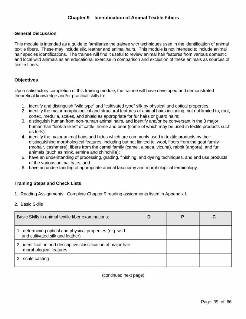
2. Basic Skills
Basic Skills in animal textile fiber examinations: D P C
1. determining optical and physical properties (e.g. wild and cultivated silk and leather)
2. identification and descriptive classification of major hair morphological features
3. scale casting
(continued next page)

Page 40 of 66
Basic Skills in animal textile fiber examinations: D P C
4. scale counting techniques
5. cross-sectioning hairs
6. medullary clearing techniques
7. measuring shield size and sub-shield strictures
3. Practical Exercises: Complete these exercises located in Appendix II.
9-1 Examining the Cuticle of Animal Hairs Part 1 Scale Margin Distance by Scale CountsPart 2 Scale Margin Appearance and Pattern by Scale Casting
9-2 Introduction to Examining Natural Fibers of Animal OriginPart 1 Examining Animal HairsPart 2 Examining Silk and Leather
(Note: this exercise should be completed in conjunction with or subsequent to learning the material presented in Chapter 11 and Chapter 12.)
Competency Evaluation
The trainee shall be evaluated by quizzes on theoretical knowledge and basic practical skills as specified in themodule objectives. The quizzes should include practical skills questions such as animal textile fiberidentification.

Page 41 of 66
Chapter 10 Identification of Inorganic Fibers
General Discussion
This module is intended to familiarize the trainee with inorganic fibers. Some classification schemes utilize theterm “mineral” fiber which can include fiber types encountered in textile products such as asbestos, glass wool,some anti-static fibers, and metallic fibers. As used in this training program manual, these fibers areconsidered manufactured and should be studied within the manufactured fiber chapters.
The use of asbestos in textile products has declined significantly due to health risks associated with thesefibers. Nevertheless, the trainee should be familiar with these inorganic fibers for thoroughness in theoreticalknowledge and for instances in which they may be encountered as fibrous evidence from sources such asbuilding and insulation products, in old textile products or the few textile products in which chrysotile may occur. This module should be completed in conjunction with Chapter 11 in which the trainee is exposed to thedetermination of fiber optical properties.
Objectives
Upon satisfactory completion of this training module, the trainee will have developed and demonstratedtheoretical knowledge and/or practical skills to:
1. be conversant in processing practices and end uses of the asbestos minerals including chrysotile,amosite, crocidolite, fibrous tremolite/actinolite, and fibrous anthophyllite from both historical and currentperspectives;
2. be conversant in the crystalline nature, chemistry and differences between layer silicates and chainsilicates;
3. determine the optical properties of asbestos fibers by polarized light microscopy, and use of thedispersion staining technique;
4. identify and classify asbestos, particularly chrysotile, based on optical properties; and5. be conversant in the applicability of infrared spectroscopy, X-ray diffraction and elemental composition examinations with respect to inorganic fiber identification.
Training Steps and Check Lists
1. Reading Assignments: Complete Chapter 10 reading assignments listed in Appendix I.
2. Basic Skills
Basic Skills in asbestos optical property examinations: D P C
1. determining refractive indices, sign of elongation, birefringence by PLM (see also Chapter 11)
2. dispersion staining
3. asbestos type identification by comparison to reference materials
Page 42 of 66
3. Practical Exercise: Complete this exercise located in Appendix II.
10-1 Identification of Asbestos Fibers
(Note: this exercise should be completed in conjunction with or subsequent to learning the material presented in Chapter 11.)
Competency Evaluation
The trainee shall be evaluated by quizzes on theoretical knowledge and basic practical skills as specified in themodule objectives. The quizzes should include practical skills questions such as determination of opticalproperties and fiber identification.

Page 43 of 66
Chapter 11 Manufactured Fiber Examinations - Optical Properties
General Discussion
This module is intended to teach the trainee proper techniques and the appropriate observations fordetermining the optical properties of manufactured fibers. Manufactured fibers include fibers that are man-made by chemical synthesis (e.g. thermoplastics, glass, steel), regenerated natural polymers (e.g. rayons), orderived from chemically modified natural polymers (e.g. cellulose acetates). Textile fibers such as fiberglass, anti-static fibers, ceramic fibers, metal fibers or metal-coated decorative threads should be included within thescope of the training. The appropriate determination and interpretation of optical properties with reference tonatural fibers is addressed in the applicable natural fiber chapters of this training program manual.
Objectives
Upon satisfactory completion of this training module, the trainee will have developed and demonstratedtheoretical knowledge and/or practical skills to:
1. determine refractive indices, sign of elongation and birefringence of fibers;2. reveal internal structures in fibers by use of appropriate mounting media;3. obtain optical property values of reference materials from literature and/or standard collection; and4. classify manufactured fibers into generic classes based on optical properties.
Training Steps and Check Lists
1. Reading Assignments: Complete Chapter 11 reading assignments listed in Appendix I.
2. Basic Skills
Basic Skills in optical property examinations: D P C
1. determining refractive indices (parallel and perpendicular) by immersion method
2. determining sign of elongation with compensators
3. determining birefringence with compensator and quartz wedge
3. Practical Exercises: Complete these exercises located in Appendix II.
11-1 Determining the Sign of ElongationPart 1 Using the First Order Red CompensatorPart 2 Using the Quartz Wedge
11-2 Measuring Fiber Birefringence 11-3 Measuring Fiber Refractive Indices by the Immersion Method

Page 44 of 66
Competency Evaluation
The trainee shall be evaluated by quizzes on theoretical knowledge and basic practical skills as specified in themodule objectives. The quizzes should include practical skills questions such as determination of opticalproperties and fiber identification.

Page 45 of 66
Chapter 12 Manufactured Fiber Examination - Cross Sections
General Discussion
This module is intended to familiarize the trainee with various fiber cross-sectioning techniques and the type ofinformation obtained from these techniques. Along with physical shape, cross sections reveal the distributionof internal structures and dye penetration. The trainee will develop proficiency in optical and physical cross-sectioning techniques.
Objectives
Upon satisfactory completion of this training module, the trainee will have developed and demonstratedtheoretical knowledge and/or practical skills to:
1. obtain satisfactory physical cross sections from single fibers, multiple fibers and fiber tufts;2. determine the modification ratio of multi-lobed fibers;3. describe observed fiber features, such as: shape, delustrant, pigment particle distribution, presence and size of spherulites or voids, dye penetration depth, and bi-component fibers;4. compare and contrast the types and quality of information obtained from optical cross-sectioning versus physical cross-sectioning; and5. observe the relationship of fiber cross-sectional shape to generic class and end usage.
Training Steps and Check Lists
1. Reading Assignments: Complete Chapter 12 reading assignments listed in Appendix I.
2. Basic Skills
Basic Skills in cross-sectioning: D P C
1. techniques for cross-sectioning multiple fibers and fiber tufts
2. techniques for cross-sectioning single fibers
3. measuring fiber dimensions in cross section
4. measuring fiber diameter and determining shape from longitudinal sections
5. calculating modification ratio from cross sections
6. observing, in cross and longitudinal sections: a. delustrant, voids, spherulites, b. pigment particles, dye penetration, c. shapes and surface treatment
Page 46 of 66
3. Practical Exercises: Complete these exercises located in Appendix II.
12-1 Cross-Sectioning Fibers and Interpretation of Cross Sections12-2 Determining the Modification Ratio of Multi-lobed Fibers
Competency Evaluation
The trainee shall be evaluated by quizzes on theoretical knowledge and basic practical skills as specified in themodule objectives. The quizzes should include practical skills questions such as determination of opticalproperties and modification ratios from fiber cross sections.

Page 47 of 66
Chapter 13 Manufactured Fiber Examination - Solubility
General Discussion
This module is intended to familiarize the trainee with solubility testing and the judicious use of this destructivetechnique. The trainee should be aware of the applicability of solubility testing in which it can provideinformation for fiber identification or distinctions that cannot easily be provided by other techniques.
Objectives
Upon satisfactory completion of this training module the trainee will have developed and demonstratedtheoretical knowledge and/or practical skills to:
1. understand the practice and applications of solubility testing;2. use solubility testing to determine fiber generic class distinctions;3. identify those situations in which solubility testing is appropriate and select appropriate tests; and4. recognize solvent reactions indicative of bi-component/bi-constituent fiber compositions.
Training Steps and Check Lists
1. Reading Assignments: Complete Chapter 13 reading assignments listed in Appendix I.
2. Basic Skills
Basic Skills in solubility testing: D P C
1. micro-sampling an appropriately sized fiber segment
2. observing and describing solubility test reactions (total/partial solubility, insolubility, swelling, shrinking, gelling, color change, and bi-component fiber differential reactions).
3. solvent washing and clearing on slide and cover slip
4. side-by-side solubility testing for comparisons
3. Practical Exercise: Complete this exercise located in Appendix II.
13-1 Solubility Testing of Acetate and Triacetate Fibers
Competency Evaluation
The trainee shall be evaluated by quizzes on theoretical knowledge and basic practical skills as specified in themodule objectives. The quizzes should include practical skills questions such as preliminary fiber identificationand distinction based on performance of solubility testing.

Page 48 of 66
Chapter 14 Manufactured Fiber Examination - Thermal Microscopy
General Discussion
This module is intended to familiarize the trainee with the use of a polarized light microscope equipped with ahot stage to observe the effect of heat on thermoplastic fibers and to determine fiber melting point. The traineeshould be aware of the applicability and the judicious use of this destructive technique.
Objectives
Upon satisfactory completion of this training module the trainee will have developed and demonstratedtheoretical knowledge and/or practical skills to:
1. set up, operate and calibrate a hot stage;2. use the hot stage for melting point determinations and observe reactivity (e.g. softening, charring,
melting, etc.); 3. identify those situations in which thermal microscopy is appropriate;4. obtain melting point values from reference materials and the literature; and5. understand alternative methods of melting point determination.
Training Steps and Check Lists
1. Reading Assignments: Complete Chapter 14 reading assignments listed in Appendix I.
2. Basic Skills
Basic Skills in melting point range determination: D P C
1. proper hot stage and microscope set-up, operation, and calibration
2. micro-sampling an appropriately sized fiber segment
3. observing and describing thermal reactions: a. droplet formation, contraction, softening, charring, melting, and b. differential reactions in bi-component or bi-constituent fibers
4. evaluating and comparing data
3. Practical Exercise: Complete this exercise located in Appendix II.
14-1 Use of a Hot Stage Part 1 Determining Melting Range of a Manufactured FiberPart 2 Identifying and Discriminating Nylon 6 and 6,6 by Melting PointsPart 3 Comparing Fibers by Melting Points
Page 49 of 66
Competency Evaluation
The trainee shall be evaluated by quizzes on theoretical knowledge and basic practical skills as specified in themodule objectives. The quizzes should include practical skills questions on the determination of melting pointranges and fiber classifications using literature references and comparison to the generated data.
Practical Examination B:
The trainee shall complete a fiber identification practical examination. The test fibers should include natural andmanufactured fibers. The trainee should be instructed to identify the fiber as completely as possible based onthe appropriate application of all methods and techniques learned to date and your laboratory’s identificationprotocol. Some fibers may be identified as to generic type, sub-generic type, or manufacturer.

Page 50 of 66
Chapter 15 Manufactured Fiber Examination - Infrared Spectroscopy
General Discussion
This module is intended to familiarize the trainee with the use of infrared spectroscopy (IR) for fiber identification and comparison by interpretation of absorption spectra. The IR is typically used in theidentification of manufactured fibers. Cellulosic fibers are indistinguishable from one another using IR. Whilethis technique does not provide sufficient information for a complete identification of cellulosic fibers, the traineewill find it useful to use IR on natural fibers to gain experience from the spectral information obtained by thistechnique.
Objectives
Upon satisfactory completion of this training module, the trainee will have developed and demonstratedtheoretical knowledge and/or practical skills to:
1. properly operate and maintain an IR and its accessories;2. have an understanding of the optical and vibrational physics of infrared absorption;3. have an understanding of the operational capabilities and limitations of the spectrometer and its accessories;4. understand the differences between conventional dispersive IR and Fourier Transform IR;5. identify those situations in which infrared analysis is appropriate;6. prepare samples by a variety of techniques; and7. obtain spectra from samples, run spectral library searches, and interpret the spectra.
Training Steps and Check Lists
1. Reading Assignments: Complete Chapter 15 reading assignments listed in Appendix I.
2. Basic Skills
Basic Skills in infrared spectroscopy: D P C
1. setting up and operating the bench and microscope, checking performance and calibration
2. adjusting apertures, objectives and condensers for optimum performance
3. sample preparation techniques
4. sample alignment and acquiring spectra
5. interpreting spectra and searching reference libraries
Page 51 of 66
3. Practical Exercises: Complete these exercises located in Appendix II.
15-1 Sample Preparation for FTIR-MicroscopyPart 1 The Effect of Fiber ThicknessPart 2 Reducing the Interference Fringes in Spectra
15-2 The Transmission/Reflection Technique15-3 Interpretation of Fiber FTIR Spectra
(Note: These exercises require substantial preparation by the trainer, see exercise preparation section.)
Competency Evaluation
The trainee shall be evaluated by quizzes on theoretical knowledge and basic practical skills as specified in themodule objectives. The quizzes should include basic skills questions such as obtaining acceptable spectrafrom samples and comparisons to reference spectra.

Page 52 of 66
Chapter 16 Fiber Examination - Comparison Microscopy
General Discussion
This module is intended to familiarize the trainee with the use of the comparison microscope and techniquesfor comparisons. This method is essential for the comparisons of physical and optical properties of fibers.
Objectives
Upon satisfactory completion of this training module, the trainee will have developed and demonstratedtheoretical knowledge and/or practical skills to:
1. prepare known fiber samples;2. properly operate and maintain the comparison microscope and its accessories;3. have an understanding of the comparison microscope optics (e.g. magnification, balancing illumination);4. perform comparison of fiber features (e.g. morphology, color, delustering agents, diameter); and5. interpret the significance of the compared fiber features.
Training Steps and Check Lists
1. Reading Assignments: Complete Chapter 16 reading assignments listed in Appendix I.
2. Basic Skills
Basic Skills in comparison microscopy: D P C
1. setting up, operating and adjusting the microscopes
2. color balancing the light sources for similar visual response to color, clarity, brightness
3. performing side-by-side fiber comparisons
4. taking photomicrographs
3. Practical Exercise: Complete this exercise located in Appendix II.
16-1 Using the Comparison Microscope with Brightfield IlluminationPart 1 Making Slides to Assist in Balancing the IlluminationPart 2 Color and Morphological Feature Comparison
(Note: This exercise requires substantial preparation by the trainer, see Part 2 preparation section.)
Page 53 of 66
Competency Evaluation
The trainee shall be evaluated by quizzes on theoretical knowledge and basic practical skills as specified in themodule objectives. The quizzes should include basic skills questions on fiber comparisons.
Practical Examination C:
The trainee shall complete a fiber identification and comparison practical examination. The trainee should beinstructed to identify and compare the fibers based on the appropriate application of all methods and techniqueslearned to date and your laboratory’s identification protocol. The test fibers should include natural andmanufactured fibers. The quantity and quality of test fibers provided for the practical examination should bevaried, but within the realm of realistic case submissions. The trainee shall be evaluated not only for achievinga correct answer as to fiber identification and comparison of known and questioned fibers, but also for criticalthinking in the selection of tests performed and the sequence in which they are performed.

Page 54 of 66
Chapter 17 Fiber Examination - Fluorescence Microscopy
General Discussion
This module is intended to familiarize the trainee with the use of the fluorescence microscope and fluorescencemicroscopy techniques. Fluorescence microscopy can be applicable to natural as well as manufacturedfibers.
Objectives
Upon satisfactory completion of this training module, the trainee will have developed and demonstratedtheoretical knowledge and/or practical skills to:
1. prepare samples and select appropriate mounting media;2. properly operate and maintain the fluorescence microscope and its accessories;3. have an understanding of the optical properties of fluorescence and the fluorescence microscope;4. perform visual examinations and comparisons to assess the presence/absence of fluorescence and its dependence on various excitation conditions;5. distinguish between fluorescence originating from dyes and that originating from optical brighteners;6. recognize fluorescence from adherent material;7. interpret the significance of the fluorescence observed during comparison; and8. understand the factors which may or may not affect fluorescence.
Training Steps and Check Lists
1. Reading Assignments: Complete Chapter 17 reading assignments listed in Appendix I.
2. Basic Skills
Basic Skills in fluorescence microscopy: D P C
1. setting up and operating the fluorescence microscope
2. optimizing the high intensity light source
3. using excitation and barrier filters
4. observing fluorescence, noting both color and intensity
5. taking photomicrographs
Page 55 of 66
3. Practical Exercises: Complete these exercises located in Appendix II.
17-1 The Fluorescence Microscope: Set-up and Operation17-2 The Effects of Mounting Media in Fluorescence Microscopy17-3 Observing Fluorescence on Fibers
Part 1 Optical BrightenersPart 2 Dyed Fibers Part 3 Contaminants
Competency Evaluation
The trainee shall be evaluated by quizzes on theoretical knowledge and basic practical skills as specified in themodule objectives. The quizzes should include basic skills questions on practical examination and comparisonof fibers, using fluorescent properties.

Page 56 of 66
Chapter 18 Fiber Examination - UV/VIS Microspectrophotometry
General Discussion
This module is intended to familiarize the trainee with the use of ultraviolet/visible light microspectrophotometryas a qualitative, quantitative and objective method of color analysis. Color analysis can be applicable to naturalas well as manufactured fibers. The calculation of complementary chromaticity coordinates is not required forcolor comparisons. However, the trainee should obtain theoretical knowledge of colorimetry for thoroughnessin understanding color analysis.
Objectives
Upon satisfactory completion of this training module, the trainee will have developed and demonstratedtheoretical knowledge and/or practical skills to:
1. properly operate and maintain the microspectrophotometer and its accessories;2. understand the optical properties of the microspectrophotometer;3. identify those situations in which microspectrophotometry is appropriate;4. prepare samples and select appropriate mounting media;5. evaluate the number of fibers required within a control sample to yield representative spectra; 6. interpret and compare spectra; and7. have an understanding of colorimetry (e.g. color intensity, hue, calculation of chromaticity coordinates).
Training Steps and Check Lists
1. Reading Assignments: Complete Chapter 18 reading assignments listed in Appendix I.
2. Basic Skills
Basic Skills in UV/VIS microspectrophotometry: D P C
1. setting up and operating the instrument, checking performance and calibration
2. adjusting illumination and detector apertures
3. setting up Köhler illumination
4. sample preparation and selection of mounting media
5. acquiring spectra and maintaining measuring parameters throughout analysis
6. interpreting and comparing spectra
Page 57 of 66
3. Practical Exercises: Complete these exercises located in Appendix II.
18-1 Microspectrophotometer Set-up and Operation 18-2 Acquiring Spectra From Single Fibers18-3 Acquiring Known Spectral Sets and Comparing Spectral Curves18-4 Examining Metameric Fibers
Competency Evaluation
The trainee shall be evaluated by quizzes on theoretical knowledge and basic practical skills as specified in themodule objectives. The quizzes should include basic skills questions on obtaining acceptable spectra andspectral curve comparisons.

Page 58 of 66
Chapter 19 Fiber Examination - Dye Analysis/Thin Layer Chromatography
General Discussion
This module is intended to familiarize the trainee with the proper application of thin layer chromatography (TLC)for fiber dye analysis and comparison. The use of TLC is applicable to natural as well as manufactured fibers.
Objectives
Upon satisfactory completion of this training module, the trainee will have developed and demonstratedtheoretical knowledge and/or practical skills to:
1. understand the physical and chemical principles of TLC;2. identify those situations in which TLC analysis is appropriate;3. use standard dye mixtures for testing eluent, extraction chemical and system performance;4. classify dyes based on fiber type and extraction reactions in various solvents; 5. select optimum eluent systems; 6. extract dyes from a variety of sample sizes;7. record and compare chromatograms for colors, fluorescence, position and intensity of bands; and8. interpret the significance of the observed chromatogram.
Training Steps and Check Lists
1. Reading Assignments: Complete Chapter 19 reading assignments listed in Appendix I.
2. Basic Skills
Basic Skills in thin layer chromatography: D P C
1. extracting dye from single fibers and bulk samples
2. effective sample application to plates
3. developing plates using appropriate eluents
4. evaluating plates with UV and VIS light
5. comparing results
Page 59 of 66
3. Practical Exercises: Complete these exercises located in Appendix II.
19-1 Classification of Fiber Dyes19-2 Thin Layer Chromatography of Fiber Dyes
Part 1 Testing of Eluents and ExtractantPart 2 TLC of Basic Dyed Acrylic Fiber Bulk SamplesPart 3 TLC of Basic Dyed Acrylic Fibers of Differing Lengths
Competency Evaluation
The trainee shall be evaluated by quizzes on theoretical knowledge and basic practical skills as specified in themodule objectives. The quizzes should include basic skills questions on sample application, plate developmentand interpretation of bands.
Practical Examination D:
The trainee shall complete a fiber identification and comparison practical examination. The trainee should beinstructed to use all applicable and appropriate methods and techniques learned to date. The test shouldinclude natural and manufactured fibers. The quantity and quality of test fibers provided for the practicalexamination should be varied, but within the realm of realistic case submissions. The trainee shall beevaluated not only for achieving a correct answer as to fiber identification and comparison, but also for criticalthinking in the selection of tests and the sequence in which they were performed.

Page 60 of 66
Chapter 20 Fiber Examination - Other Techniques
General Discussion
This module is intended to familiarize the trainee with a variety of other instrumental techniques that may beapplied to fiber and textile examinations. This module is written as a development of the trainee’s theoreticalknowledge of these techniques. If your laboratory uses any of these methodologies, then the trainer shallamend this module to include specifically stated learning objectives, reading assignments, basic skillsdemonstrations, and practical exercises.
Objectives
Upon satisfactory completion of this training module, the trainee will have developed theoretical knowledge ofthe applicability and use of alternative methodologies in fiber examinations including, but not limited to, the useof:
1. scanning electron microscopy/energy dispersive spectroscopy;2. pyrolysis-gas chromatography, pyrolysis-mass spectrometry, pyrolysis-FTIR;3. capillary electrophoresis and high-performance liquid chromatography for dye analysis; and4. Raman spectroscopy and emission spectroscopy.
Training Steps and Check Lists
1. Reading Assignments: Complete Chapter 20 reading assignments listed in Appendix I.
Competency Evaluation
The trainee shall be evaluated by quizzes on the theoretical knowledge as specified in the module objectives. Ifthis module has been amended (as described above) to include specifically stated objectives, readingassignments and basic skills, then the quizzes should include basic practical skills questions relevant to theamendment.

Page 61 of 66
Chapter 21 Textile Examinations
General Discussion
This module is designed to familiarize the trainee with the examination and comparison of yarns, threads,fabrics and buttons. This will include the identification and possible cause of physical damage to textilematerials, physical matching, and fabric impressions.
Objectives
Upon satisfactory completion of this training module, the trainee will have developed and demonstratedtheoretical knowledge and/or practical skills to:
1. understand textile terminology, examination and comparison techniques for physical construction and composition of yarns, threads, fabrics and buttons;
2. identify and assess characteristics of physical damage to textile materials;3. describe characteristics used to assess taphonomy of physical damage;4. examine and compare fabric impressions; and5. examine textile materials for physical matches.
Training Steps and Check List
1. Reading Assignments: Complete Chapter 21 reading assignments listed in Appendix I.
2. Basic Skills
Basic Skills in textile examinations: D P C
1. examining and comparing textile yarns and threads
2. examining and comparing fabrics
3. comparing buttons
4. determining type of physical damage
5. assessing taphonomy of physical damage
6. examining and comparing fabric impressions
7. examining textiles for physical matches
Page 62 of 66
3. Practical Exercises: Complete these exercises located in Appendix II.
21-1 Examining Fabric Damage 21-2 Environmental, Chemical and Mechanical Effects on Fabrics
Competency Evaluation
The trainee shall be evaluated by quizzes on the theoretical knowledge and basic practical skills as specified inthe module objectives. The quizzes should include practical skills questions on identification of fabric: physicalconstruction, pattern, identification of warp and weft, fiber content, and fabric impressions, etc.

Page 63 of 66
Chapter 22 Cordage Examinations
General Discussion
This module is designed to familiarize the trainee with the examination and comparison of cordage, to includeconstruction and fiber content. This module is not intended to teach the trainee identification of knots. Thecordage terminology used may vary within the literature.
Objectives
Upon satisfactory completion of this training module, the trainee will have developed and demonstratedtheoretical knowledge and/or practical skills to:
1. understand cordage terminology, examination and comparison techniques for physical construction and composition;
2. identify and assess characteristics of physical damage to cordage materials;3. determine characteristics used to assess taphonomy of physical damage;4. examine and compare cordage impressions; and5. examine cordage for physical matches.
Training Steps and Check Lists
1. Reading Assignments: Complete Chapter 22 reading assignments listed in Appendix I.
2. Basic Skills
Basic Skills in cordage examinations: D P C
1. physical description of cordage
2. examining and comparing cordage
3. examining and comparing cordage impressions
4. determining types of physical damage
5. assessing taphonomy of physical damage
6. examining cordage for physical matches
3. Practical Exercises: Complete these exercises located in Appendix II.
22-1 Composition and Physical Construction of Natural and Manufactured Fiber Cordage22-2 Environmental, Chemical and Mechanical Effects on Natural and Manufactured Fiber Cordage
Page 64 of 66
Competency Evaluation
The trainee shall be evaluated by quizzes on theoretical knowledge and basic practical skills as specified in themodule objectives. The quizzes should include practical skills questions on the determination of cordageconstruction and fiber content.
Practical Examination E:
The trainee shall complete a textile and cordage practical examination which should include construction andcomposition, physical matching, physical impressions, and assessment of damage and wear. The traineeshould be instructed to use all applicable and appropriate methods and techniques in compliance withlaboratory protocol. The textile and cordage samples should include those composed of natural fibers as wellas those composed of manufactured fibers. The quantity and quality of test materials provided for the practicalexamination should be varied, but within the realm of realistic case submissions. The trainee shall beevaluated not only for achieving a correct answer, but also for critical thinking in the selection of testsperformed and the sequence in which they are performed.
Page 65 of 66
Chapter 23 Interpretation and Presentation
General Discussion
This module is designed to serve as a mechanism for the trainee to integrate the factors that affect evidenceinterpretations and the significance of fiber evidence. Although these topics should have been routinelyaddressed in each chapter throughout the training, the intent is to perform some academic exercises to drawall topics together at the end of the training period. The trainee is directed to review and interpret casedocumentation. The trainee is then to write a report of his/her findings. The trainer should review and discussthese results with the trainee.
Objectives
Upon satisfactory completion of this training module, the trainee will have developed and demonstratedtheoretical knowledge and/or practical skills to:
1. draw appropriate conclusions from analytical data;2. understand the factors affecting the data and its interpretation;3. understand the significance of fiber evidence;4. understand the application of statistics;5. write complete and unbiased analytical reports with appropriate conclusions and opinions; and6. provide appropriate testimony.
Training Steps and Check Lists
1. Reading Assignments: Complete Chapter 23 reading assignments listed in Appendix I.
2. Interpretive Exercises:
The trainee should be given a predetermined number of “cases” for analysis, composed of either analyticaldata, case evidence or simulated evidence depending on what is available in the laboratory. Any material givenshould be handled as evidence under laboratory protocol. The number of interpretive exercises or re-examinations should be determined by the trainer and laboratory policy.
Based on the provided or generated information, the trainee should prepare an analytical report for each case. The examination notes and report prepared by the trainee should be evaluated for completeness and discussedwith the trainee. The trainee’s report should be compared to the report prepared by the experienced examinerand discussed with the trainee as part of the evaluation when appropriate.
A written record of the satisfactory completion of this Interpretive Exercise should be maintained and may berecorded in the Practical Exercise completion table provided in Chapter 2. Individual exercise assignmentsmay be noted below as a record of casework interpretive exercises or casework re-examinations.

Page 66 of 66
Case or Exercise Identifier Date Assigned Satisfactory Completion (date and initials of trainer and trainee)
1.
2.
3.
4.
5.
6.
Competency Evaluation
The final progression to certification of competency as an independent fiber examiner shall be reviewed asspecified in Chapter 2 of this training program manual. In accordance with those specifications, the traineeshall complete:
1. Supervised Casework
The trainee should be prepared to perform all aspects of supervised casework after satisfactory completion ofall readings, basic skills acquisitions, practical exercises and examinations specified in this training program tothis point. Upon concurrence of the trainer and laboratory management, the trainee should begin all aspects ofsupervised casework. The number of cases to be completed by the trainee should be determined by yourlaboratory’s protocol. A complete record of these cases and casework evaluations should be maintained andmay be recorded as provided for in Chapter 2.
2. Mock Trial
At least one mock trial should be conducted as part of this training program. Mock trial(s) shall be conducted inaccordance with your laboratory’s protocol and may be recorded as provided for in Chapter 2.
3. Written Examination
The final written examination for this training program shall be administered and may be recorded as providedfor in Chapter 2.
4. Certification of Competency
The trainee shall be evaluated by review of all training records generated through this training program, andshall receive a written certificate of competency before performance of independent casework. A suggestedformat for final competency certification is provided in Chapter 2.
APPENDIX I Page 1 of 24
APPENDIX IREADING ASSIGNMENTS
TOPIC PAGE
READING ASSIGNMENT USER’S GUIDE 2
READING ASSIGNMENTS
Chapter 3 Introduction to Fibers and Textiles 3
Chapter 4 Fiber Transfer and Persistence 4
Chapter 5 Casework Familiarization/Search and Recovery 5
Chapter 6 Microscopy Review 6
Chapter 7 Fiber Examinations/Preliminary Observations 7
Chapter 8 Identification of Vegetable Fibers 8
Chapter 9 Identification of Animal Textile Fibers 9
Chapter 10 Identification of Inorganic Fibers 10
Chapter 11 Manufactured Fiber Examination - Optical Properties 11
Chapter 12 Manufactured Fiber Examination - Cross Sections 12
Chapter 13 Manufactured Fiber Examination - Solubility 13
Chapter 14 Manufactured Fiber Examination-Thermal Microscopy 14
Chapter 15 Manufactured Fiber Examination - Infrared Spectroscopy 15
Chapter 16 Fiber Examination - Comparison Microscopy 16
Chapter 17 Fiber Examination - Fluorescence Microscopy 17
Chapter 18 Fiber Examination - UV/VIS Microspectrophotometry 18
Chapter 19 Fiber Examination - Dye Analysis/TLC 19
Chapter 20 Fiber Examination - Other Techniques 20
Chapter 21 Textile Examinations 22
Chapter 22 Cordage Examinations 23
Chapter 23 Interpretation and Presentation 24
APPENDIX I Page 2 of 24
READING ASSIGNMENTS USER’S GUIDE
Reading assignments are selected to give the trainee a broad range of understanding of current and pastthoughts on various topics. The reading assignments intended to give the trainee a sound theoreticalbackground are designated as required, and are considered mandatory. Supplemental readings should besought out by the trainee and may be specified by the trainer or laboratory policy. Continued exposure to theforensic literature should encourage further professional development, reveal alternate opinions in certainsubject areas, and present some possible research topics. Some reading assignments may appear redundant. However, re-reading some assignments is thought to be beneficial because the trainee will have some newlylearned skills, practical experience and/or perspectives which will make the literature more meaningful.
The reading assignments are designated by Chapter. The trainee should place their initials and date in thespace provided to the left of each Required Reading reference upon completion of the reading assignment aspart of the training record. Space is provided for addition of a written record of Supplemental Readingscompleted by the trainee. The references and bibliographies in the required readings are a good source ofmaterial for the supplemental readings.
A number of general reference texts, including dictionary and encyclopedic sources, should be made availablefor the trainee’s use throughout the training period. The trainee should refer to the General Reference books forall material relevant to each Chapter topic. These readings should also be recorded as SupplementalReadings in the space provided upon completion. The following texts are recommended:
American Fabrics and Fashions Magazine, editor. Encyclopedia of Textiles, 3rd edition. Englewood Cliffs,NJ: Prentice-Hall, 1980.
Brady GS, Clauser HR, Vaccari JA. Materials Handbook, 15th edition. New York: McGraw-Hill ProfessionalPublishing, 2002.
Dictionary of Fiber and Textile Technology. Charlotte, NC: Hoechst-Celanese Corp.,1990.
Grayson M, editor. Encyclopedia of Textiles, Fibers, and Nonwoven Fabrics. New York: John Wiley & Sons,Inc., 1984.
Hall D. Practical Fiber Identification Auburn, AL: Auburn University, 1982.
Hatch KL. Textile Science. Minneapolis, MN: West Information Publishing Group, 1993.
Heyn ANJ. Fiber Microscopy: A Textbook and Laboratory Manual. New York: Interscience Publishers, 1954.
Kuehni RG. Color: An Introduction to Practice and Principles. New York: Wiley Interscience, Inc., 1997.
Luniak B. Identification of Textile Fibres, Qualitative and Quantitative Analysis of Fibre Blends, 2nd edition.London: Pitman, 1953.
Mauersberger H, editor. Matthews’ Textile Fibers, 6th edition. New York: John Wiley & Sons, Inc., 1975.
Raheel M, editor. Modern Textile Characterization Methods, New York: Marcel Dekker Publisher, 1996.
The Textile Institute. Identification of Textile Materials, 7th edition. Portsmouth NJ: Grosvenor Press, 1975.
APPENDIX I Page 3 of 24
Chapter 3 Introduction to Fibers and Textiles Reading Assignment
Completion ReferenceDate & Initials
Required Readings
David SK, Pailthorpe MT. Classification of textile fibres: production, structure, and properties. In:Robertson J, Grieve MC, editors. Forensic Examination of Fibres, 2nd edition. London: Francis & Taylor,1999;1-31.
Gaudette B. The forensic aspects of textile fiber examination. In: Saferstein R, editor. ForensicScience Handbook, Vol. II. Englewood Cliffs, NJ: Prentice-Hall Inc., 1988; 209-214.
Grieve MC, Wiggins KG. Fibers under fire: suggestions for improving their use to provide forensicevidence. J Forensic Sci 2001;46(4):835-843.
Joseph ML. Joseph’s Introductory Textile Science, 6th edition. New York: International ThomsonPublishing, 1992.
Scientific Working Group for Materials Analysis (SWGMAT). Forensic Fiber Examination Guidelines,Chapter 1 Introduction to fiber examinations. Forensic Sci Commun Apr 1999; 1(1) available on theInternet at www.fbi.gov .
Supplemental Readings
APPENDIX I Page 4 of 24
Chapter 4 Fiber Transfer and Persistence Reading Assignment
Completion ReferenceDate & Initials
Required Readings
Akulova V, Vasiliauskiene D, Talaliene D. Further insights into the persistence of transferred fibres onoutdoor clothes. Sci Justice 2002; 42(3):165-171.
Annis PA, Bresee RR, Cooper TR. Influence of textile structure on single fiber transfer from wovenfabrics. Textile Research J 1992; 65(2):293-301.
Coxon A, Grieve M, Dunlop J. A method of assessing the fibre shedding potential of fabrics. J ForensicSci Soc 1992; 32:151-158.
Gaudette B. The forensic aspects of textile fiber examination. In: Saferstein R, editor. ForensicScience Handbook, Vol. II. Englewood Cliffs, NJ: Prentice-Hall Inc., 1988; 214-221, 255-259.
Grieve MC, Dunlop J, Haddock PS. Transfer experiments with acrylic fibres. Forensic Sci Int 1989;40:267-277.
Palmer R. The retention and recovery of transferred fibers following the washing of recipient clothing. J Forensic Sci 1997; 43(3):502-504.
Pounds C A, Smalldon KW. The transfer of fibres between clothing materials during simulatedcontacts and their persistence during wear, part I. J Forensic Sci Soc 1975;15:17-27.
Pounds C A, Smalldon KW. The transfer of fibres between clothing materials during simulatedcontacts and their persistence during wear, part II. J Forensic Sci Soc 1975;15:29-7.
Pounds C A, Smalldon KW. The transfer of fibres between clothing materials during simulatedcontacts and their persistence during wear, part III. J Forensic Sci Soc 1975;15:197-207.
Robertson J, Roux C. Transfer, persistence and recovery of fibres. In: Robertson J, Grieve MC,editors. Forensic Examination of Fibres, 2nd edition. London: Francis & Taylor, 1999; 89-100.
Robertson J, Lloyd AK. Redistribution of textile fibres following transfer during simulated contacts. J Forensic Sci Soc 1984; 24:3-7.
Salter MT, Cook R, Jackson AR. Differential shedding from blended fabrics. Forensic Sci Int 1987; 33:155-164.
Scientific Working Group for Materials Analysis (SWGMAT). Trace Evidence Recovery Guidelines, Part4 Contamination and loss. Forensic Sci Commun Oct 1999; 1(3) available on the Internet atwww.fbi.gov .
Supplemental Readings
APPENDIX I Page 5 of 24
Chapter 5 Casework Familiarization/Search and Recovery Reading Assignment
Completion ReferenceDate & Initials
Required Readings
All applicable parts of your laboratory’s policy and standard operating procedures manuals covering thetopics of:
• health and safety practices• quality assurance• general evidence handling, analytical, and reporting procedures
Biermann TW. Fiber finder systems. In: In: Robertson J, Grieve MC, editors. Forensic Examination ofFibres, 2nd edition. London: Francis & Taylor, 1999;135-152.
Farley MA. Legal standards for the admissibility of novel scientific evidence. In: Saferstein R, editor.Forensic Science Handbook, Vol. III. Englewood Cliffs, NJ: Prentice-Hall Inc., 1993; 1-23.
Gaudette B. The forensic aspects of textile fiber examination. In: Saferstein R, editor. ForensicScience Handbook, Vol. II. Englewood Cliffs, NJ: Prentice-Hall Inc., 1988; 218-272.
Dignan SJ, Murphy KJ. Fibre evidence from fingernail clippings. Can Soc For Sci J 2002; 35(1):17-21.
Grieve MC Influential factors, quality assurance, report writing and case examples. In: Robertson J,Grieve MC, editors. Forensic Examination of Fibres, 2nd edition. London: Francis & Taylor, 1999; 343-361.
Moore JE, Jackson G, Firth M. Movement of fibres between working areas as a result of routineexamination of garments. J For Sci Soc 1986; 26:433-440.
Palenik S. Microscopy and microchemistry of physical evidence. In: Saferstein R, editor. ForensicScience Handbook, Vol. II. Englewood Cliffs, NJ: Prentice-Hall Inc., 1988; 161-208.
Robertson J. Protocols for fibre examination and initial preparation. In: Robertson J, Grieve MC,editors. Forensic Examination of Fibres, 2nd edition. London: Francis & Taylor, 1999;116-134.
Roux C, Huttuen J, Rampling K, Robertson J. Factors affecting the potential for fibre contamination inpurpose-designed forensic search rooms. Sci Justice 2001; 41:135-144.
Springer F. Collection of fibre evidence from crime scenes. In: Robertson J, Grieve MC, editors.Forensic Examination of Fibres, 2nd edition. London: Francis & Taylor, 1999;101-115.
Scientific Working Group for Materials Analysis (SWGMAT). Trace Evidence Recovery Guidelines.Forensic Sci Commun Oct 1999; 1(3) available on the Internet at www.fbi.gov .
Scientific Working Group for Materials Analysis (SWGMAT). Trace Evidence Quality AssuranceGuidelines. Forensic Sci Commun Jan 2000; 2(1) available on the Internet at www.fbi.gov .
Supplemental Readings
APPENDIX I Page 6 of 24
Chapter 6 Microscopy Review Reading Assignment
Completion ReferenceDate & Initials
Required Readings
DeForest PR. Foundations of forensic microscopy. In: Saferstein R, editor. Forensic ScienceHandbook, Vol. I, 2nd edition. Englewood Cliffs, NJ: Regents/Prentice-Hall Inc., 2002; 215-319.
McCrone WC, McCrone LB, Delly JB. Polarized Light Microscopy. Chicago: McCrone ResearchInstitute, 2002.
Palenik S. Microscopical examination of fibres. In: Robertson J, Grieve MC, editors. ForensicExamination of Fibres; 2nd edition. London: Taylor & Francis, 1999; 153-177.
The instruction manuals provided by the manufacturer(s) of your laboratory’s stereomicroscope,transmitted light and polarized light microscopes.
Your laboratory’s standard operating procedures and quality assurance procedures governingmicroscope operation and maintenance.
Supplemental Readings
APPENDIX I Page 7 of 24
Chapter 7 Fiber Examinations/Preliminary Observations Reading Assignment
Completion ReferenceDate & Initials
Required Readings
David SK, Pailthorpe MT. Classification of textile fibres: production, structure, and properties. In:Robertson J, Grieve MC, editors. Forensic Examination of Fibres, 2nd edition. London: Francis & Taylor,1999;1-31.
Gaudette B. The forensic aspects of textile fiber examination. In: Saferstein R, editor. ForensicScience Handbook, Vol. II. Englewood Cliffs, NJ: Prentice-Hall Inc., 1988; 222-230, 238-241.
Palenik S. Microscopical examination of fibres. In: Robertson J, Grieve MC, editors. ForensicExamination of Fibres, 2nd edition. London: Francis & Taylor, 1999;153-177.
Robertson J. Protocols for fibre examination and initial preparation. In: Robertson J, Grieve MC,editors. Forensic Examination of Fibres, 2nd edition. London: Francis & Taylor, 1999;116-134.
Scientific Working Group for Materials Analysis (SWGMAT), Forensic fiber examination guidelines,Chapter 2 Microscopy of textile fibers. Forensic Sci Apr 1999; 1(1) available on the Internet atwww.fbi.gov .
Your laboratory’s fiber standard operating procedures governing preliminary examinations,interpretation and reporting.
Supplemental Readings
APPENDIX I Page 8 of 24
Chapter 8 Identification of Vegetable Fibers Reading Assignment
Completion ReferenceDate & Initials
Required Readings
Catling D, Grayson J. Identification of Vegetable Fibres. London: Chapman and Hall, 1982.
David SK, Pailthorpe MT. Classification of textile fibres: production, structure, and properties. In:Robertson J, Grieve MC, editors. Forensic Examination of Fibres, 2nd edition. London: Francis & Taylor,1999;1, 8-15.
Palenik S. Microscopical examination of fibres. In: Robertson J, Grieve MC, editors. ForensicExamination of Fibres, 2nd edition. London: Francis & Taylor, 1999;156-159.
Robertson J. Protocols for fibre examination and initial preparation. In: Robertson J, Grieve MC,editors. Forensic Examination of Fibres, 2nd edition. London: Francis & Taylor, 1999;124-128.
Wiggins K. Ropes and cordage. In: Robertson J, Grieve MC, editors. Forensic Examination of Fibres,2nd edition. London: Francis & Taylor, 1999; 59.
Your laboratory’s fiber standard operating procedures governing vegetable fiber examinations,interpretation and reporting.
Supplemental Readings
General References Specific to Natural Fibers
Cook JG. Handbook of Textile Fibres-Natural Fibres, 5th edition, Durham UK: Merrow, 1984.
Friesen PL Natural Fibers Information Guide, 2nd edition, Dennisport, MA: Crane, 1994.
APPENDIX I Page 9 of 24
Chapter 9 Identification of Animal Textile Fibers Reading Assignment
Completion ReferenceDate & Initials
Required Readings
David SK, Pailthorpe MT. Classification of textile fibres: production, structure, and properties. In:Robertson J, Grieve MC, editors. Forensic Examination of Fibres, 2nd edition. London: Francis & Taylor,1999;1-31.
Gaudette B. The forensic aspects of textile fiber examination. In: Saferstein R, editor. ForensicScience Handbook, Vol. II. Englewood Cliffs, NJ: Prentice-Hall Inc., 1988; 209-214, 239-241.
Your laboratory’s fiber standard operating procedures governing animal fiber examinations,interpretation and reporting.
Supplemental Readings
General References Specific to Fibers of Animal Origin
Appleyard HM. Guide to the Identification of Animal Fibres. Leeds, UK: WIRA, the research and services centrefor textiles and clothing, 1978.
Debrot S. Atlas Des Poils De Mammiferes D’Europe. Pereux, Suisse: Imprimerie de l’Ouest S.A., 1982.
Moore TD, Spence LE, Dubnolle CE. Identification of the Dorsal Guard Hairs of Some Mammals of Wyoming.Cheyenne, WY: Wyoming Game and Fish Department, Bulletin No. 14, 974.
APPENDIX I Page 10 of 24
Chapter 10 Identification of Inorganic Fibers Reading Assignment
Completion ReferenceDate & Initials
Required Readings
Deer WA, Howie RA, Zussman J. An Introduction to the Rock-Forming Minerals. New York: Addison-Wesley Publishing, 1992. (Note: read sections on asbestiform minerals; specific pages vary in differenteditions.)
McCrone WC, Asbestos Identification, 2nd edition. Chicago: McCrone Research Institute, 1987.
McCrone WC, McCrone LB, Delly JB. Polarized Light Microscopy. Chicago: McCrone ResearchInstitute, 2002; 169-196.
Your laboratory’s fiber standard operating procedures governing inorganic fiber examinations,interpretation and reporting.
Supplemental Readings
APPENDIX I Page 11 of 24
Chapter 11 Manufactured Fiber Examination - Optical Properties Reading Assignment
Completion ReferenceDate & Initials
Required Readings
Gaudette B. The forensic aspects of textile fiber examination. In: Saferstein R, editor. ForensicScience Handbook, Vol. II. Englewood Cliffs, NJ: Prentice-Hall Inc., 1988; 223-230.
McCrone WC, McCrone LB, Delly JB. Polarized Light Microscopy. Chicago: McCrone ResearchInstitute, 2002; 142-149.
Palenik S. Microscopical examination of fibres. In: Robertson J, Grieve MC, editors. ForensicExamination of Fibres, 2nd edition. London: Francis & Taylor, 1999;153-177.
Robertson J. Protocols for fibre examination and initial preparation. In: Robertson J, Grieve MC,editors. Forensic Examination of Fibres, 2nd edition. London: Francis & Taylor, 1999;116-134.
Your laboratory’s fiber standard operating procedures governing fiber microscopical examinations,interpretation and reporting.
Supplemental Readings
APPENDIX I Page 12 of 24 PPENDIX I Page 11 of 24
Chapter 12 Manufactured Fiber Examination - Cross Sections Reading Assignment
Completion ReferenceDate & Initials
Required Readings
Gaudette B. The forensic aspects of textile fiber examination. In: Saferstein R, editor. ForensicScience Handbook, Vol. II. Englewood Cliffs, NJ: Prentice-Hall Inc., 1988; 228-231.
Grieve MC. New Fibre types. In: Robertson J, Grieve MC, editors. Forensic Examination of Fibres, 2nd edition. London: Francis & Taylor, 1999;399-419.
Palenik S. Microscopical examination of fibres. In: Robertson J, Grieve MC, editors. ForensicExamination of Fibres, 2nd edition. London: Francis & Taylor, 1999;161-163.
Your laboratory’s fiber standard operating procedures governing fiber crosssection examinations,interpretation and reporting.
Supplemental Readings
APPENDIX I Page 13 of 24
Chapter 13 Manufactured Fiber Examination - Solubility Reading Assignment
Completion ReferenceDate & Initials
Required Readings
David SK, Pailthorpe MT. Classification of textile fibres: production, structure, and properties. In:Robertson J, Grieve MC, editors. Forensic Examination of Fibres, 2nd edition. London: Francis & Taylor,1999;1-31.
Gaudette B. The forensic aspects of textile fiber examination. In: Saferstein R, editor. ForensicScience Handbook, Vol. II. Englewood Cliffs, NJ: Prentice-Hall Inc., 1988; 236-237.
Your laboratory’s fiber standard operating procedures governing solubility examinations, interpretationand reporting.
Supplemental Readings
APPENDIX I Page 14 of 24
Chapter 14 Manufactured Fiber Examination - Thermal Microscopy Reading Assignment
Completion ReferenceDate & Initials
Required Readings
Gaudette B. The forensic aspects of textile fiber examination. In: Saferstein R, editor. ForensicScience Handbook, Vol. II. Englewood Cliffs, NJ: Prentice-Hall Inc., 1988; 233, 236.
Palenik S. Microscopical examination of fibres. In: Robertson J, Grieve MC, editors. ForensicExamination of Fibres, 2nd edition. London: Francis & Taylor, 1999;170-172.
The instruction manuals provided by the manufacturer(s) of your laboratory’s microscope(s) and hotstage apparatus.
Your laboratory’s fiber standard operating procedures governing thermal microscopy examinations,interpretation and reporting.
Supplemental Readings
APPENDIX I Page 15 of 24
Chapter 15 Manufactured Fiber Examination - Infrared Spectroscopy Reading Assignment
Completion ReferenceDate & Initials
Required Readings
Bartick EG, Tungol MW. Infrared microscopy and its forensic applications. In: Saferstein R, editor.Forensic Science Handbook, Vol. III. Englewood Cliffs, NJ: Prentice-Hall Inc., 1993: 196-252.
Cho L, Reffner JA, Gatewood BM, Wetzel DL. Single fiber analysis by internal reflectionmicrospectroscopy. J Forensic Sci 2001; 46(6):1309-1314.
Cho L, Reffner JA, Gatewood BM, Wetzel DL. A new method for fiber comparison using polarizedinfrared microspectroscopy. J Forensic Sci 1999; 44(2):275-282.
Cho L, Reffner JA, Wetzel DL. Forensic classification of polyester fibers by Infrared dichroic ratiopattern recognition. J Forensic Sci 1999; 44(2):283-291.
Katon JE. Infrared microscopy. A review of fundamentals and applications. Micron, 1996; 27: 303-314.
Kirkbride KP, Tungol MW. Infrared microscopy of fibres. In: Robertson J, Grieve MC, editors. ForensicExamination of Fibres, 2nd edition. London: Francis & Taylor, 1999;179-222.
Scientific Working Group for Materials Analysis (SWGMAT). Forensic Fiber Examination Guidelines,Chapter 6 Infrared analysis of textile fibers. Forensic Sci Commun Apr 1999; 1(1) available on theInternet at www.fbi.gov .
The instruction manuals provided by the manufacturer(s) of your laboratory’s IR instrumentation.
Your laboratory’s fiber standard operating procedures governing infrared spectroscopy examinations,interpretation and reporting.
Supplemental Readings
APPENDIX I Page 16 of 24
Chapter 16 Comparison Microscopy Reading Assignment
Completion ReferenceDate & Initials
Required Readings
DeForest PR. Foundations of forensic microscopy. In: Saferstein R, editor. Forensic ScienceHandbook, Vol. I, 2nd edition. Englewood Cliffs, NJ: Regents/Prentice-Hall Inc., 2002; 232, 234.
Gaudette B. The forensic aspects of textile fiber examination. In: Saferstein R, editor. ForensicScience Handbook, Vol. II. Englewood Cliffs, NJ: Prentice-Hall Inc., 1988; 241-245.
Robertson J. Protocols for fibre examination and initial preparation. In: Robertson J, Grieve MC,editors. Forensic Examination of Fibres, 2nd edition. London: Francis & Taylor, 1999;121-124.
The instruction manuals provided by the manufacturer of your laboratory’s comparison microscope.
Your laboratory’s fiber standard operating procedures governing comparison microscopyexaminations, interpretation and reporting.
Supplemental Readings
APPENDIX I Page 17 of 24
Chapter 17 Fluorescence Microscopy Reading Assignment
Completion ReferenceDate & Initials
Required Readings
Abramowitz M. Fluorescence Microscopy, The Essentials”, Vol. 4, Basics and Beyond Series. Melville,NY: Olympus America Inc., 1993; 1-22.
McCrone WC, McCrone LB, Delly JB. Polarized Light Microscopy. Chicago: McCrone ResearchInstitute, 2002; 64-68.
The instruction manuals provided by the manufacturer of your laboratory’s fluorescence microscope.
Your laboratory’s fiber standard operating procedures governing fluorescence microscopyexaminations, interpretation and reporting.
Supplemental Readings
APPENDIX I Page 18 of 24
Chapter 18 Fiber Examination - UV/VIS Microspectrophotometry Reading Assignment
Completion ReferenceDate & Initials
Required Readings
Adolf FP, Dunlop J. Microspectrophotometry/colour measurement. In: Robertson J, Grieve MC,editors. Forensic Examination of Fibres, 2nd edition. London: Francis & Taylor, 1999;1252-289.
Gaudette B. The forensic aspects of textile fiber examination. In: Saferstein R, editor. ForensicScience Handbook, Vol. II. Englewood Cliffs, NJ: Prentice-Hall Inc., 1988; 245-248.
Grieve MC, Biermann TW, Davignon M. The evidential value of black cotton fibres. Sci Justic 2001;41(4):245-260.
Scientific Working Group for Materials Analysis (SWGMAT). Forensic Fiber Examination Guidelines,Chapter 3 Visible spectroscopy of textile fibers. Forensic Sci Commun Apr 1999; 1(1) available on theInternet at www.fbi.gov .
The instruction manuals provided by the manufacturer of your laboratory’s instrumentation.
Your laboratory’s fiber standard operating procedures governing microspectrophotometryexaminations, interpretation and reporting.
Supplemental Readings
General References Specific to Color
McLaren K. The Colour Science of Dyes and Pigments. Bristol, UK: Adam Hilger, 1983.
Venkataraman K. The Analytical Chemistry of Synthetic Dyes. New York: John Wiley & Sons, 1977.
APPENDIX I Page 19 of 24
Chapter 19 Fiber Examination - Dye Analysis/TLC Reading Assignment
Completion ReferenceDate & Initials
Required Readings
Gaudette B. The forensic aspects of textile fiber examination. In: Saferstein R, editor. ForensicScience Handbook, Vol. II. Englewood Cliffs, NJ: Prentice-Hall Inc., 1988; 248-254.
Scientific Working Group for Materials Analysis (SWGMAT). Forensic Fiber Examination Guidelines,Chapter 4 Thin layer chromatography of non-reactive dyes in textile fibers. Forensic Sci Commun Apr1999; 1(1) available on the Internet at www.fbi.gov .
Wiggins KG. Thin layer chromatographic analysis for fibre dyes. In: Robertson J, Grieve MC, editors.Forensic Examination of Fibres, 2nd edition. London: Francis & Taylor, 1999; 291-310.
Your laboratory’s fiber standard operating procedures governing fiber dye analysis and TLC examinations, interpretation and reporting.
Supplemental Readings
General References Specific to TLC or Dyes
Hamilton R, Hamilton S. Thin Layer Chromatography. Chichester, UK: John Wiley & Sons, Inc., 1987.
Sherma J, Fried B, editors. Handbook of Thin Layer Chromatography. New York: Marcel Dekker Publishers,1990.
Society of Dyers and Colourists. The Colour Index, 4th edition, Vols. 1-6, Research Triangle Park, NC: AATCC,1985.
Stahl E. Thin Layer Chromatography. New York: Springer Verlag, 1969.
APPENDIX I Page 20 of 24
Chapter 20 Fiber Examination - Other Techniques Reading Assignment
Completion ReferenceDate & Initials
Required Readings
The instruction manuals provided by the manufacturer(s) of your laboratory’s instrumentation whichmay be applicable under this chapter topic.
Your laboratory’s standard operating procedures governing any examinations, interpretation andreporting that may be applicable under this chapter topic.
CE
Robertson J. Capillary electrophoresis. In: Robertson J, Grieve MC, editors. Forensic Examination ofFibres, 2nd edition. London: Francis & Taylor, 1999; 328-336.
HPLC
Davila-Jimenex, Elizalde-Gonzalez, Gutierrez-Gonzalez, Pelaez-Cid. Electrochemical treatment oftextile dyes and their analysis by high-performance liquid chromatography with diode array detection. J Chromatography 2000; 889 (1-2): 253-259.
Kretschmer K, Kelbig W. Differentiation of commercial polyester fibers using two dimensional high-performance liquid chromatography (HPLC) and multivariate pattern recognition techniques. J ForensicSci 1992; 37(3):727-737.
Griffin R, Speers J. High-performance liquid chromatography. In: Robertson J, Grieve MC, editors.Forensic Examination of Fibres, 2nd edition. London: Francis & Taylor, 1999; 311-327.
Pyrolysis
Challinor JM. Fibre identification by pyrolysis techniques. In: Robertson J, Grieve MC, editors.Forensic Examination of Fibres, 2nd edition. London: Francis & Taylor, 1999; 223-238.
Scientific Working Group for Materials Analysis (SWGMAT). Forensic Fiber Examination Guidelines,Chapter 5 Pyrolysis-gas chromatography of textile fibers. Forensic Sci Commun Apr 1999; 1(1)available on the Internet at www.fbi.gov .
SEM
Roux C. Scanning electron microscopy and elemental analysis. In: Robertson J, Grieve MC, editors.Forensic Examination of Fibres, 2nd edition. London: Francis & Taylor, 1999; 239-250.
Spectroscopy:
Cho L, Reffner JA, Gatewood BM, Wetzel DL. A new method for fiber comparison using polarizedinfrared microspectroscopy. J Forensic Sci 1999; 44(2):275-282.
APPENDIX I Page 21 of 24
Haberhaus-Troyer, Crnoja, Rosenberg, and Grasserbauer. Surface characterization of commercialfibers for solid-phase microextraction and related problems in their applications. J Anal Chem 2000;366(4):329-331.
Howell HE, Davis JR. Qualitative identification of fibers using NIR spectroscopy. Textile Chemist andColorist 1991; 23(9):69-72.
Keen I, White G, Fredericks P. Characterization of fibers by Raman microprobe spectroscopy. JForensic Sci 1998; 43(1):82-89.
Kokot S, Tuan NA, Rintoul L. Discrimination of reactive dyes on cotton fabric by Raman spectroscopyand chemometrics. Applied Spectroscopy 1997; 51(3):387-395.
Lang, Katon, O’Keefe, and Schiering. The identification of fibers by infrared and Ramanmicrospectroscopy. Microchemical Journal 1986; 34:319-331.
White P. Surface enhanced resonance Raman scattering spectroscopy. In: Robertson J, Grieve MC,editors. Forensic Examination of Fibres, 2nd edition. London: Francis & Taylor, 1999; 337-342.
Supplemental Readings
General Reference Specific to Other Techniques Topic
Mastura R, editor, Modern Textile Characterization Methods. New York: Marcel Dekker Publisher, 1996;Chapter 3 Surface Characterization of Textiles Using SEMChapter 4 Investigation of Textiles by Analytical PyrolysisChapter 5 Liquid Chromatographic Techniques in Textile Analysis
APPENDIX I Page 22 of 24
Chapter 21 Textile Examinations Reading Assignment
Completion ReferenceDate & Initials
Required Readings
Adolf FP. The structure of textiles: an introduction to the basics. In: Robertson J, Grieve MC, editors.Forensic Examination of Fibres, 2nd edition. London: Francis & Taylor, 1999; 33-54.
Amick JF, Beheim CW. Screen-printing ink transfer in a sexual assault case. J Forensci Sci 2002:47(3):619-624.
Scientific Working Group for Materials Analysis (SWGMAT). Forensic Fiber Examination Guidelines,Chapter 7 Fabrics and Cordage. Forensic Sci Commun Apr 1999; 1(1) available on the Internet atwww.fbi.gov .
Taupin JM, Adolf FP, Robertson J. Examination of damage to textiles. In: Robertson J, Grieve MC,editors. Forensic Examination of Fibres, 2nd edition. London: Francis & Taylor, 1999; 65-87.
Your laboratory’s fiber standard operating procedures governing textile, fabric impressions andphysical match examinations, interpretation and reporting.
Supplemental Readings
APPENDIX I Page 23 of 24
Chapter 22 Cordage Examinations Reading Assignment
Completion ReferenceDate & Initials
Required Readings
Scientific Working Group for Materials Analysis (SWGMAT). Forensic Fiber Examination Guidelines,Chapter 7 Fabrics and Cordage. Forensic Sci Commun Apr 1999; 1(1) available on the Internet atwww.fbi.gov .
Wiggins KG. Ropes and cordage. In: Robertson J, Grieve MC, editors. Forensic Examination ofFibres, 2nd edition. London: Francis & Taylor, 1999; 55-64.
Your laboratory’s fiber standard operating procedures governing cordage and physical matchexaminations, interpretation and reporting.
Supplemental Readings
APPENDIX I Page 24 of 24
Chapter 23 Interpretation and Presentation Reading Assignment
Completion ReferenceDate & Initials
Required Readings
Champod C, Taroni F. The Bayesian approach. In: Robertson J, Grieve MC, editors. ForensicExamination of Fibres, 2nd edition. London: Francis & Taylor, 1999; 379-398.
Cook R, Evett IW, Jackson G, Jones P, Lambert JA. A model for case assessment and interpretation.Sci Justice 1998; 38(3):151-156.
Evett IW, Jackson G, Lambert JA, McCrossan S. The impact of the principles of evidence interpretationon the structure and content of statements. Sci Justice 2000: 40:233-239.
Gaudette B. The forensic aspects of textile fiber examination. In: Saferstein R, editor. ForensicScience Handbook, Vol. II. Englewood Cliffs, NJ: Prentice-Hall Inc., 1988; 255-261.
Grieve MC. A survey on the evidential value of fibres and on the interpretation of the findings in fibretransfer cases. Part 1-fibre frequencies. Sci Justice 2000; 40(3):189-200.
Grieve MC. A survey on the evidential value of fibres and on the interpretation of the findings in fibretransfer cases. Part 2-interpretation and reporting. Sci Justice 2000; 40(3):201-209.
Grieve MC. Influential factors, quality assurance, report writing and case examples. In: Robertson J,Grieve MC, editors. Forensic Examination of Fibres, 2nd edition. London: Francis & Taylor, 1999; 343-361.
Houck M. Statistics and trace evidence: the tyranny of numbers. Forensic Sci Commun Oct 1999; 1(3) available on the Internet at www.fbi.gov .
Sapir G. Legal aspects of forensic science. In: Saferstein R, editor. Forensic Science Handbook, Vol. I, 2nd edition. Englewood Cliffs, NJ: Regents/Prentice-Hall Inc., 2002; 1-39.
Starrs J. Mountebanks among forensic scientists. In: Saferstein R, editor. Forensic ScienceHandbook, Vol. II. Englewood Cliffs, NJ: Prentice-Hall Inc., 1988; 1-37.
Tontarski RE. What you see is what you believe. J Forensic Sci Soc 1991; 31(2):279-281.
Web-Salter M, Wiggins KG. Aids to interpretation. In: Robertson J, Grieve MC, editors. ForensicExamination of Fibres, 2nd edition. London: Francis & Taylor, 1999; 364-378.
Your laboratory’s fiber standard operating procedures governing examination, interpretation andreporting.
Supplemental Readings
APPENDIX II Page 1 of 128
APPENDIX IIPRACTICAL EXERCISES
TOPIC PAGE
PRACTICAL EXERCISE USER’S GUIDE 3
PRACTICAL SAFETY ISSUES 4
PRACTICAL EXERCISES
Chapter 5 Casework Familiarization/Search and Recovery5-1 Fiber Transfer and Persistence 55-2 Collecting Fibers on Tape 7
Chapter 6 Microscopy Review6-1 Familiarization with the Stereomicroscope 106-2 Familiarization with the Compound Light Microscope 136-3 Familiarization with the Polarized Light Microscope 17
Chapter 7 Fiber Examinations/Preliminary Observations7-1 Fiber Manipulations: Removing Fibers from Tape and Mounting 227-2 Observing Effects of Mounting Media 257-3 Observing Fiber Shape, Surface and Internal Structure 287-4 Observing Color and Pleochroism 317-5 Distinguishing Natural and Manufactured Fiber Classes 33
Chapter 8 Identification of Vegetable Fibers8-1 Microscopy of Non-woody Vegetable Fibers 368-2 Determining Natural Fiber Twist 39
Chapter 9 Identification of Animal Textile Fibers9-1 Examining the Cuticle of Animal Hairs 429-2 Introduction to Examining Natural Fibers of Animal Origin 45
Chapter 10 Identification of Inorganic Fibers
10-1 Identification of Asbestos Fibers 49
Chapter 11 Manufactured Fiber Examination - Optical Properties11-1 Determining the Sign of Elongation 5211-2 Measuring Fiber Birefringence 5611-3 Measuring Fiber Refractive Indices by the Immersion Method 59
Chapter 12 Manufactured Fiber Examination - Cross Sections12-1 Cross-sectioning Fibers and Interpretation of Cross Sections 6212-2 Determining the Modification Ratio of Multi-lobed Fibers 65
Chapter 13 Manufactured Fiber Examination - Solubility13-1 Solubility Testing of Acetate and Triacetate Fibers 68
APPENDIX II Page 2 of 128
TOPIC PAGE
Chapter 14 Manufactured Fiber Examination - Thermal Microscopy 14-1 Use of a Hot Stage 71
Chapter 15 Manufactured Fiber Examination - Infrared Spectroscopy15-1 Sample Preparation for FTIR-Microscopy 7415-2 The Transmission/Reflection Technique 7815-3 Interpretation of Fiber FTIR Spectra 81
Chapter 16 Fiber Examination - Comparison Microscopy16-1 Using the Comparison Microscope with Brightfield Illumination 87
Chapter 17 Fiber Examination - Fluorescence Microscopy17-1 The Fluorescence Microscope: Set-up and Operation 9117-2 The Effects of Mounting Media in Fluorescence Microscopy 9417-3 Observing Fluorescence on Fibers 96
Chapter 18 Fiber Examination - UV/VIS Microspectrophotometry18-1 Microspectrophotometer Set-up and Operation 9918-2 Acquiring Spectra from Single Fibers 10218-3 Acquiring Known Spectral Sets and Comparing Spectral Curves 10518-4 Examining Metameric Fibers 109
Chapter 19 Fiber Examination - Dye Analysis/TLC19-1 Classification of Fiber Dyes 11119-2 Thin Layer Chromatography of Fiber Dyes 114
Chapter 21 Textile Examinations21-1 Examining Fabric Damage 11821-2 Environmental, Chemical and Mechanical Effects on Fabrics 121
Chapter 22 Cordage Examinations22-1 Composition and Construction of Cordage 12422-2 Environmental, Chemical and Mechanical Effects on Cordage 127
APPENDIX II Page 3 of 128
PRACTICAL EXERCISE USER’S GUIDE
These practical exercises are designed to expose the trainee to the basic skills learned within each chapter,and to develop observational and interpretational skills related to the data collected by use of the basic skills. These practical exercises are not comprehensive for the totality of practical exposure a fiber examiner traineeshould receive. Rather, these exercises should serve as a stimulus for the trainee to extend their practicalexperience through their own curiosity and intellect in self-tutorials of their own design, or by expansion orvariations on the existing exercises. Toward this goal of gaining additional practical experience, the traineeshould be given reasonable and adequate time to continue their experimentation beyond these requiredpractical exercises.
All practical exercises should be completed by the trainee with full and complete note-taking, and report writing,if appropriate. The exercises should be reviewed by the trainer with particular attention to development of thetrainee’s critical thinking skills, as well as continuous review of learned basic skills.
The practical exercises are all organized with the following format and intent:
• Subject the title and topic of the exercise
• Time the anticipated minimum time required to perform the hands-on work; additionaltime shall be allotted for reading, preparation and note-taking
• Objective brief statement of the purpose of the exercise
• Theory brief statement(s) of the theoretical knowledge basis for the exercise, meant todirect the trainee’s attention and to highlight the relevant points in the literatureand exercise
• References mandatory readings that should be initialed and dated when completed
• Preparation statement of activities required prior to beginning the exercise
• Materials statement of supplies and equipment needed
• Safety good laboratory safety practices are always expected, a brief statement here ismeant to alert a trainee to some safety issues that they may not have routinelyencountered before (see comments below)
• Directions instructions for performing the exercise
• Observations statement(s) to direct the trainee’s attention to appropriate types of observations,note-taking and data organization; statements may be reiterative with instructionsgiven in the Directions section in some exercises
• Discussion a brief discussion of the pertinent observations, information, interpretations andconclusions that the trainee should have made if the exercise was performedcorrectly; including a statement of the exercise’s relevance to other topics in thetraining program and suggestions for additional self-directed explorations in someexercises
A record of satisfactory practical exercise completions shall be kept. The “Record of Practical ExerciseCompletion” table located in Chapter 2 may be used for this purpose.

APPENDIX II Page 4 of 128
PRACTICAL SAFETY ISSUES
Fiber examiners (and trainees) come into contact with virtually all of the potentially dangerous physical(temperature, radiations and voltages), chemical and biological hazards present in the laboratory. Thefollowing brief reminders are made to draw particular attention to a few issues that a trainee should be aware ofas a supplement to any existing laboratory policies and procedures, and/or safety manuals.
1. Appropriate health and safety practices should always be considered mandatory. Review your laboratory’spolicies and procedures on these topics.
2. Know where your laboratory’s safety equipment (e.g. eye washes, safety showers, first aid kits, spill kits, fireextinguishers, etc.) is located, how to properly use the equipment and when/under what circumstances to usethe equipment.
3. Always wear any personal protective equipment that is appropriate for the task(s) at hand. Utilize anyappropriate engineering and/or work place practices to minimize risk.
4. All instrumentation should be inspected at least annually to ensure that all optical, mechanical and electricalcomponents are in clean and safe operating condition. Heed all manufacturer’s warnings about the safehandling, use and maintenance procedures of any instrumentation.
5. Material Safety Data Sheets (MSDS) or other relevant safety information should be reviewed for allchemicals an individual intends to use.
6. Virtually all mounting media could be considered hazardous. Different mountants contain volatile materials,corrosive compounds, teratogenic or carcinogenic materials, acute poisons, halogenated hydrocarbons orpolychlorinated biphenyls (PCB’s). Individuals should consider that microscopy will bring them, and othersworking near them, into close tactile and respiratory contact with these chemicals.
7. Be cognizant of the possibility that the evidentiary item(s) you are working with may have biological andchemical hazards associated with them, or may have chemical residues from previous examinations.
8. Special eye protection should be worn whenever using some alternate light sources such as intense UVlight and lasers.
9. Explosion proof face shielding and hand protection should be worn while handling high pressure lampassemblies such as xenon or mercury vapor lamps or hot lamp housings. The protection should be sufficientto protect against both thermal and fragmentation wounds. Do not attempt to handle or replace these or otherlight sources until you have been properly trained to do so.
10. Always use “sharps” with extra caution, following any recommended engineering and work practices tominimize the hazard they pose. Dispose of “sharps” with extra caution in a proper “sharps” disposal container.
11. Warning signs should be posted whenever chemicals or radiation may pose a hazard to individualsentering the work area.
12. Immediately report any health and safety problem of which you become aware. Take other action toremedy the problem or minimize risk in those situations in which it is appropriate and possible.
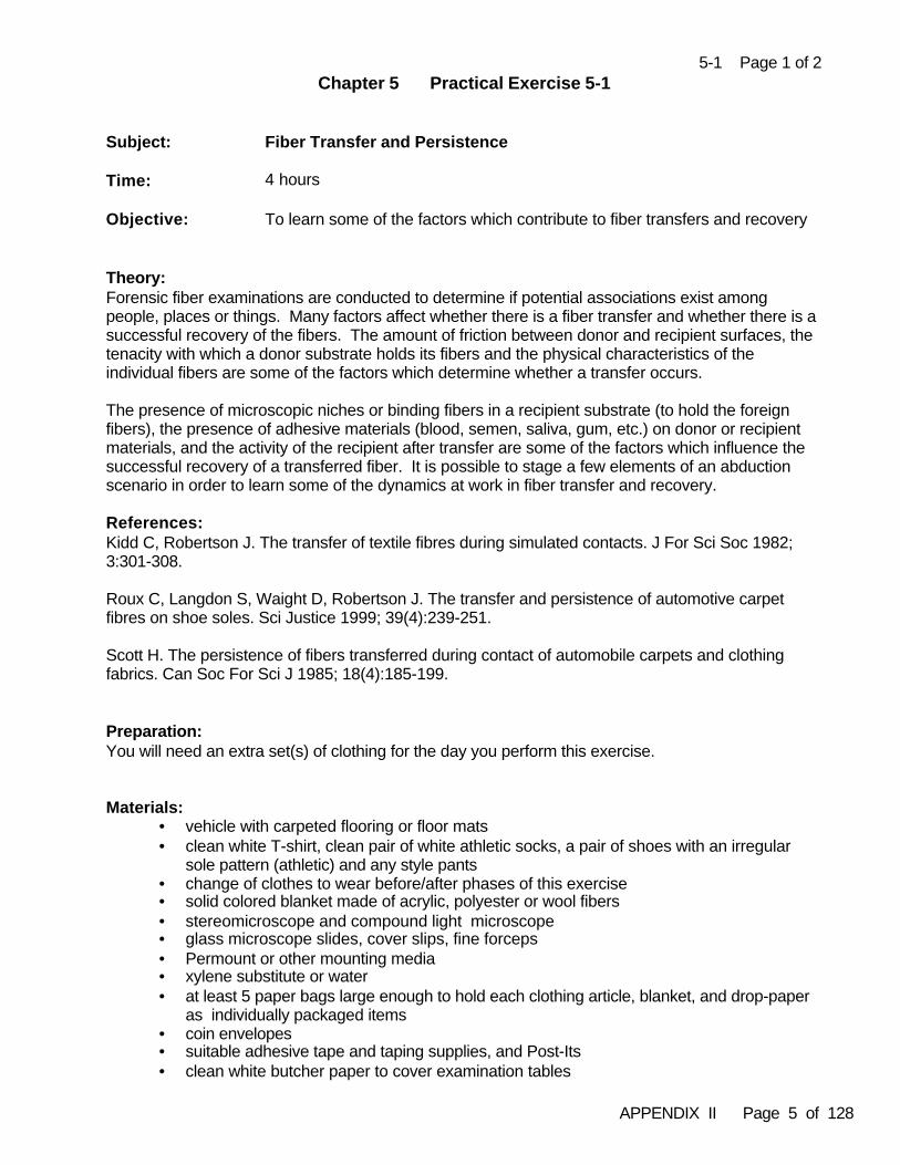
APPENDIX II Page 5 of 128
5-1 Page 1 of 2Chapter 5 Practical Exercise 5-1
Subject: Fiber Transfer and Persistence
Time: 4 hours
Objective: To learn some of the factors which contribute to fiber transfers and recovery
Theory: Forensic fiber examinations are conducted to determine if potential associations exist amongpeople, places or things. Many factors affect whether there is a fiber transfer and whether there is asuccessful recovery of the fibers. The amount of friction between donor and recipient surfaces, thetenacity with which a donor substrate holds its fibers and the physical characteristics of theindividual fibers are some of the factors which determine whether a transfer occurs.
The presence of microscopic niches or binding fibers in a recipient substrate (to hold the foreignfibers), the presence of adhesive materials (blood, semen, saliva, gum, etc.) on donor or recipientmaterials, and the activity of the recipient after transfer are some of the factors which influence thesuccessful recovery of a transferred fiber. It is possible to stage a few elements of an abductionscenario in order to learn some of the dynamics at work in fiber transfer and recovery.
References:Kidd C, Robertson J. The transfer of textile fibres during simulated contacts. J For Sci Soc 1982;3:301-308.
Roux C, Langdon S, Waight D, Robertson J. The transfer and persistence of automotive carpetfibres on shoe soles. Sci Justice 1999; 39(4):239-251.
Scott H. The persistence of fibers transferred during contact of automobile carpets and clothingfabrics. Can Soc For Sci J 1985; 18(4):185-199.
Preparation: You will need an extra set(s) of clothing for the day you perform this exercise.
Materials:
• vehicle with carpeted flooring or floor mats • clean white T-shirt, clean pair of white athletic socks, a pair of shoes with an irregular
sole pattern (athletic) and any style pants• change of clothes to wear before/after phases of this exercise• solid colored blanket made of acrylic, polyester or wool fibers• stereomicroscope and compound light microscope • glass microscope slides, cover slips, fine forceps• Permount or other mounting media• xylene substitute or water• at least 5 paper bags large enough to hold each clothing article, blanket, and drop-paper
as individually packaged items • coin envelopes• suitable adhesive tape and taping supplies, and Post-Its• clean white butcher paper to cover examination tables
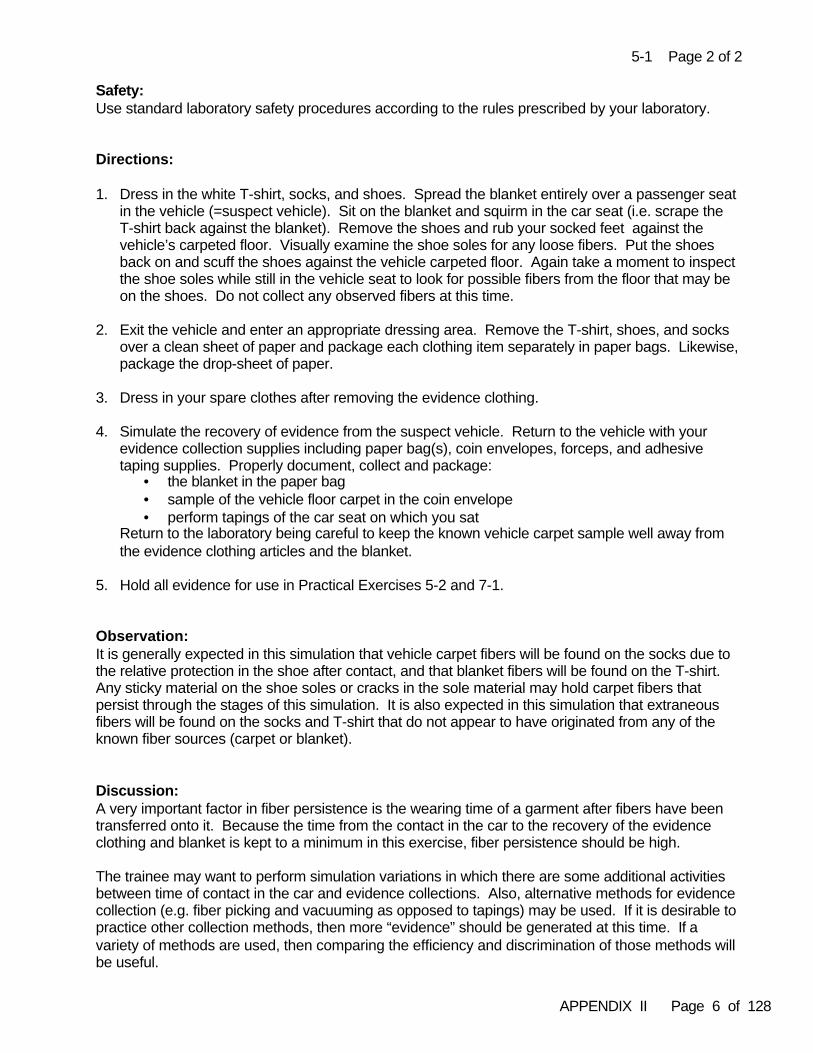
APPENDIX II Page 6 of 128
5-1 Page 2 of 2
Safety:Use standard laboratory safety procedures according to the rules prescribed by your laboratory.
Directions:
1. Dress in the white T-shirt, socks, and shoes. Spread the blanket entirely over a passenger seatin the vehicle (=suspect vehicle). Sit on the blanket and squirm in the car seat (i.e. scrape the T-shirt back against the blanket). Remove the shoes and rub your socked feet against thevehicle’s carpeted floor. Visually examine the shoe soles for any loose fibers. Put the shoesback on and scuff the shoes against the vehicle carpeted floor. Again take a moment to inspectthe shoe soles while still in the vehicle seat to look for possible fibers from the floor that may beon the shoes. Do not collect any observed fibers at this time.
2. Exit the vehicle and enter an appropriate dressing area. Remove the T-shirt, shoes, and socksover a clean sheet of paper and package each clothing item separately in paper bags. Likewise,package the drop-sheet of paper.
3. Dress in your spare clothes after removing the evidence clothing.
4. Simulate the recovery of evidence from the suspect vehicle. Return to the vehicle with yourevidence collection supplies including paper bag(s), coin envelopes, forceps, and adhesivetaping supplies. Properly document, collect and package:
• the blanket in the paper bag• sample of the vehicle floor carpet in the coin envelope• perform tapings of the car seat on which you sat
Return to the laboratory being careful to keep the known vehicle carpet sample well away fromthe evidence clothing articles and the blanket.
5. Hold all evidence for use in Practical Exercises 5-2 and 7-1.
Observation:It is generally expected in this simulation that vehicle carpet fibers will be found on the socks due tothe relative protection in the shoe after contact, and that blanket fibers will be found on the T-shirt.Any sticky material on the shoe soles or cracks in the sole material may hold carpet fibers thatpersist through the stages of this simulation. It is also expected in this simulation that extraneousfibers will be found on the socks and T-shirt that do not appear to have originated from any of theknown fiber sources (carpet or blanket).
Discussion: A very important factor in fiber persistence is the wearing time of a garment after fibers have beentransferred onto it. Because the time from the contact in the car to the recovery of the evidenceclothing and blanket is kept to a minimum in this exercise, fiber persistence should be high.
The trainee may want to perform simulation variations in which there are some additional activitiesbetween time of contact in the car and evidence collections. Also, alternative methods for evidencecollection (e.g. fiber picking and vacuuming as opposed to tapings) may be used. If it is desirable topractice other collection methods, then more “evidence” should be generated at this time. If avariety of methods are used, then comparing the efficiency and discrimination of those methods willbe useful.
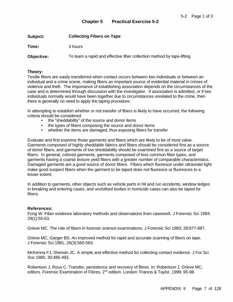
APPENDIX II Page 7 of 128
5-2 Page 1 of 3Chapter 5 Practical Exercise 5-2
Subject: Collecting Fibers on Tape
Time: 3 hours
Objective: To learn a rapid and effective fiber collection method by tape-lifting
Theory: Textile fibers are easily transferred when contact occurs between two individuals or between anindividual and a crime scene, making fibers an important source of evidential material in crimes ofviolence and theft. The importance of establishing association depends on the circumstances of thecase and is determined through discussion with the investigator. If association is admitted, or if twoindividuals normally would have been together due to circumstances unrelated to the crime, thenthere is generally no need to apply the taping procedure.
In attempting to establish whether or not transfer of fibers is likely to have occurred, the followingcriteria should be considered:
• the “sheddability” of the source and donor items• the types of fibers composing the source and donor items• whether the items are damaged, thus exposing fibers for transfer
Evaluate and first examine those garments and fibers which are likely to be of most value. Garments composed of highly sheddable fabrics and fibers should be considered first as a sourceof donor fibers, and garments of low sheddability should be examined first as a source of targetfibers. In general, colored garments, garments composed of less common fiber types, andgarments having a coarse texture yield fibers with a greater number of comparable characteristics. Damaged garments are a good source of donor fibers. Fibers which fluoresce under ultraviolet lightmake good suspect fibers when the garment to be taped does not fluoresce or fluoresces to alesser extent.
In addition to garments, other objects such as vehicle parts in hit and run accidents, window ledgesin breaking and entering cases, and unclothed bodies in homicide cases can also be taped forfibers.
References:Fong W. Fiber evidence laboratory methods and observations from casework. J Forensic Sci 1984;29(1):55-63.
Grieve MC. The role of fibers in forensic science examinations. J Forensic Sci 1983; 28:877-887.
Grieve MC, Garger BS. An improved method for rapid and accurate scanning of fibers on tape. J Forensic Sci 1981; 26(3):560-563.
McKenna FJ, Sherwin JC. A simple and effective method for collecting contact evidence. J For SciSoc 1985; 30:485-493,
Robertson J, Roux C. Transfer, persistence and recovery of fibres. In: Robertson J, Grieve MC,editors. Forensic Examination of Fibres, 2nd edition. London: Francis & Taylor, 1999; 95-98.
APPENDIX II Page 8 of 128
5-2 Page 2 of 3
Preparation:Separate the items to be taped by source i.e. victim, suspect and scene. Ensure that each item youhave been given is properly sealed in its own container. Items from different sources should betaped in different rooms to ensure that airborne transfer of fibers between sources does not occur. A different laboratory coat must be worn for taping items from different sources. Clean theexamination tables in each room thoroughly.
Materials:• three clean laboratory coats• disposable gloves• several acetate document protectors, or equivalent• adhesive tape• permanent marker• brush• two clothing items reportedly from the victim• two clothing items reportedly from the accused• one bed sheet from the scene• the packaged evidence items you collected during Practical Exercise 5-1• evidence packaging material
Safety:Disposable gloves must be worn to avoid possible contact with body fluids present on the clothingitems to be examined.
Directions:
1. Collect control tapings of the table surface prior to opening any of the items to be taped. Labelan acetate sheet with the proper markings and discard the exposed portion of tape from the tapedispenser. Remove approximately eight inches of tape, holding each end between index fingerand thumb. Press the tape firmly against the table surface in several areas until the tape haslost most its stickiness. Press the tape onto the interior portion of the acetate sheet. Repeat theprocedure until all areas of the table have been sampled.
2. Brush off the outside of the item container to remove adhering contaminant fibers prior to placingit on the clean examination table. Remove the item from its packaging and spread it out on thetable. Prepare acetate sheets with the appropriate markings for each area to be taped.Systematically tape the entire garment by area following the basic tape handling procedure asdescribed above. Once taping is complete, sample a portion of the garment for use as a knownsample by cutting out a square piece of fabric and retain it in a properly sealed and labeledcontainer.
3. Return the item to its packaging ensuring that it is properly resealed. Clean the examinationtable thoroughly, change gloves, and repeat the procedure for the other item from the samesource. Remove your laboratory coat when completed and leave it in the examination room.
4. Repeat steps 1 through 3 to examine and tape the items from the other sources. Each sourceshould be examined in a separate room, using new and clean laboratory coats for each room.
APPENDIX II Page 9 of 128
5-2 Page 3 of 3
5. Prepare acetate sheets for comparison purposes containing fibers on tape taken from theknown samples.
6. Examine your tape-lifts visually and with a magnifying glass. Do you see any evidence ofsample contamination?
7. Once you are confident that you can perform the tape-lifting technique without contamination andloss, repeat this exercise using the questioned and known samples that you collected whileperforming Practical Exercise 5-1. Examine your tape-lifts visually and with a magnifying glass.Do you see preliminary evidence of possible fiber transfers?
8. Save all of your tape-lift samples for use in Practical Exercise 7-1.
Observations:If the examination table surface was properly cleaned before starting, then the control tapes shouldbe almost completely fiber free. If a paper towel or cotton rag was used to wipe the table surface,then a small amount of fibers corresponding to the towel or rag will be observed on the controltapes.
Observing the tapings from the clothing and blanket should reveal a medium to high number offibers adhering to the tapings. The bulk of these fibers will be from the fabric that composes thesearticles, with transferred fibers being present in much smaller quantities. A thorough examinationutilizing a stereomicroscope will reveal the transferred or target fibers, which can then be removedfrom the tapes for analyses.
If you performed Practical Exercise 5-1 and attempted to collect fibers by methods such as pickingand vacuuming, then generally compare the efficiency and discrimination capabilities of the picking,taping and vacuuming recovery methods.
Discussion:Tape-lifting is generally a rapid and efficient method for recovering transferred fibers. Single fibersmay appear colorless when viewed under a stereomicroscope. Different colored backgrounds(usually black and white) and different illuminating conditions should be used to make the targetfibers more visible.
Other fiber recovery methods can be used and the choice of method is based, in part, on thecircumstances of the investigation. Picking single fibers during a visual search is highlydiscriminatory but can be time consuming. Vacuuming is rapid but so indiscriminate that use of thistechnique is often discouraged.
APPENDIX II Page 10 of 128
6-1 Page 1 of 3Chapter 6 Practical Exercise 6-1
Subject: Familiarization with the Stereomicroscope
Time: 4 hours
Objective: To learn the basic components, limitations and value of the stereomicroscope
Theory: An initial step in the preliminary examination of evidence should include an overall viewing of theitems in question. This can be accomplished through stereomicroscopical examination. In contrastto the restricted stage-objective distance with compound microscopes, the open stage area of thestereomicroscope allows greater flexibility for viewing large samples. Evidence can be freelyrotated and moved to obtain information from all angles. The lower magnification of a stereo-microscope also provides a greater viewing area of the evidence offering an opportunity to put thedamaged or altered area in perspective with the item as a whole. Objects viewed through thestereomicroscope are not reversed as with the compound microscope. Viewed items will retaintheir three-dimensional characteristics under stereomicroscopical examination due to separateoptical systems for each eye. These qualities in conjunction with the reflected light source will allowviewing of the evidence in its naturally perceived state, varied only by magnification. The low level ofmagnification still allows fiber characterizations, such as reflected light color, crimp, length, relativediameter and damage. In addition, it allows the discrimination of natural, synthetic or inorganicfibers. Yarn and fabrics can also be examined for basic construction.
References:Scientific Working Group for Materials Analysis (SWGMAT). Forensic Fiber Examination Guidelines,Chapter 2 Microscopy of textile fibers. Forensic Sci Commun Apr 1999; 1(1) available on the Internetat www.fbi.gov .
Taupin J M, Adolf FP, Robertson J. Examination of damage to textiles. In: Robertson J, Grieve MC,editors. Forensic Examination of Fibres, 2nd edition. London: Francis & Taylor, 1999; 66, 82.
Preparation:Take one (1) five-inch square of the knit fabric and snugly fit it over the head of a hammer. Securethe fabric by twisting a rubber band several times around the hammer neck. With the fabricsecured, forcefully hit the fabric-covered hammerhead onto a painted surface at an angle ofapproximately 45 degrees. Repeat striking, if necessary, until an impression is visible. Repeat theprocedure with woven fabric sections, to include plain and twill.
Materials:• stereomicroscope• blunt tip forceps• dissecting needles or sharp tip forceps• rubber bands• one (1) five inch square section of dyed plain woven fabric sample• one (1) five inch square section of dyed woven twill fabric sample• one (1) five inch square section of knit fabric sample• painted surface (section of car, bicycle or wood)• hammer

APPENDIX II Page 11 of 128
6-1 Page 2 of 3
Safety:Use standard laboratory safety procedures according to the rules prescribed by your laboratory. Use caution when wielding the hammer, make sure your hands and other people are not withinstriking range.
Directions:If there is a need to move the stereomicroscope for use, then carry the microscope with one handsupporting the base and the other hand holding the arm.
1. Place the hammer head on the microscope stage and view for possible fiber transfer. If thelight source is free standing, then the angle of the light path may be changed to provide bettervisualization.
2. Remove the hammer and place one of the fabric sections onto the stage area inside thecircle of light. Higher quality stereomicroscopes are equipped with a zoom lens system or arotating drum containing multiple objectives that are use to increase and decrease overallmagnification. Select an objective magnification. Your selection will depend upon the detailnecessary for the examination.
3. Note the construction of the fabric. Move the fabric around on the stage until all areashave been viewed. Flip the fabric over and repeat your observations.
4. Using blunt tweezers to hold the fabric down, take the dissecting needles or sharp tipforceps and push apart the yarns at the cut edge. Note the direction of twist for the yarn. Note whether all fibers appear similar within the yarn.
5. Separating out a single fiber, note the color and compare this to your color interpretationfor the complete piece of fabric.
6. Move the fabric section around on the stage to view the damaged area. While changing themagnification, observe and record the damage to yarns/fibers and the impression made. Take measurements to compare with the measurement of the hammer head. Note thedegree and form of paint transfer.
7. Repeat with the remaining fabric sections.
Observations: The color hue of an individual fiber may appear the same as the color for the whole fabric samplewhen using stereomicroscopic magnification. But, this is not necessarily true in all instances,especially with lightly colored fabrics. Fibers from fabrics that were dyed or printed afterconstruction will show “white” areas where dye was blocked due to the overlapping of another fiber. Fibers that were dyed prior to construction will show a continuance of color over the length of thestrand. If the fabric was printed, then there will be a multitude of color changes along the fiberlength.
Woven fabric damage occurs through all yarns. Did the fabric damage created by the hammerhead result in a crescent shaped separation? The yarn tips appear frayed and uneven, an exampleof blunt damage. The damage with knit fabrics results in “holes” or “thinning” due to the reinforcedlayering of yarns from the knitting stitch. In part, the amount of force used will determine whethersufficient detail is present for comparison between the damaged area and the hammer.
Paint transfer does occur, and can be viewed on the individual fabric surface yarns or embedded inthe fabric.
APPENDIX II Page 12 of 128
6-1 Page 3 of 3
Discussion:The stage area of the stereomicroscope provides an excellent tool for gross observations. Largeitems are easily handled, and collected debris samples from clothing scrapings or crime scenerecovery can be readily searched. At this point any noted debris attached to the fabric, yarn or fibercan be used to determine the direction of the examination. Minute traces of paint, grease, glass, soilor other debris may provide invaluable associative information overlooked by the investigatingagency. This debris may also be used in conjunction with the fiber analysis to associate aquestioned sample to a known source.
At this level of stereomicroscopic examination it may be determined that the evidentiary fiber exhibitscharacteristics (such as the color, diameter, crimp or adhering debris) that are significantly differentfrom the known source and, thus, will eliminate the need for further examination.
Fiber color represents a readily apparent trait allowing easy fiber recognition and recovery. The eyenaturally is attracted to bright or different color hues and because of this, manufacturers provide considerable variability in fiber colors.
Fabric construction (woven, knit or pressed) can be compared to evidentiary fabric pattern transfersas may occur in hit-and-run cases, or in cases involving contact transfer with wet fabric. Thestereomicroscope is an invaluable resource when conducting physical matches. A questionedsection of fabric or cordage is aligned with the known fabric or cordage through systematicdemonstration of yarn absence or extension from one piece to another.
The fiber examiner should recognize the importance of basic microscopical examination. Whileincreased magnification is important for fiber examination, many informative characteristics can beobtained from stereomicroscopic examination, including characteristics that would be missed iffibers were to be immediately prepared for instrumental analysis.
APPENDIX II Page 13 of 128
6-2 Page 1 of 4Chapter 6 Practical Exercise 6-2
Subject: Familiarization with the Compound Light Microscope
Time: 6 hours
Objective: To learn the proper procedures for correct illumination of a compoundtransmitted light microscope and calibrating the ocular micrometer
Theory:In order to obtain the best resolving power and specimen contrast that your microscope will allow,proper illumination of that instrument must be obtained. The most readily accepted technique toobtain this is Köhler Illumination. This technique is based on positioning and alignment of thevarious optical elements of your microscope (lamp condenser, substage condenser, objective,ocular, and light source) to produce two sets of conjugate images. One image is observedorthoscopically (no Bertrand lens) and the other conoscopically (with the Bertrand lens or anequivalent in place). In the orthoscopic view with good Köhler Illumination, the field diaphragm,specimen and ocular front focal plane (cross hairs or micrometer) are simultaneously in good focuson the retina and centered on the microscope axis. In the conoscopic view with good KöhlerIllumination, the lamp filament, substage aperture diaphragm, objective back focal plane and ocularback focal plane are simultaneously in good focus on the retina and centered on the microscopeaxis.
Many modern microscopes are now equipped with a ground glass diffuser in the illumination systemso that the lamp filaments cannot be observed and are usually not adjustable. Therefore, trueKöhler illumination cannot be obtained.
The measurement of particle size is an important tool for microscopists. Measurements of fiberdiameter can be used, in part, to determine fiber generic class and end uses, and is a physicalfeature used in fiber comparisons. Fibers and other particles can be accurately measured by usingthe linear scales (micrometer) in the microscope ocular. However, the scales must be calibratedbefore use.
References:Goldberg O. Köhler illumination. The Microscope 1980;28:15-2.
McCrone W C. Checklist for true Köhler illumination. American Laboratory 1980;12(1):96-98.
McCrone WC, McCrone LB, Delly JB. Polarized Light Microscopy. Chicago: McCrone ReasearchInstitute, 2002; 30-34 (illumination), 99-107 (micrometry).
Preparation: Obtain the following premounted fiber samples from your trainer:
• colorless, round, moderately delustered polyester• dyed, round, moderately delustered polyester• colorless trilobal nylon• dyed trilobal nylon
APPENDIX II Page 14 of 128
6-2 Page 2 of 4
Materials: • compound transmitted light or polarized light microscope• microscope objectives of various magnification (e.g. 4X,10X, 20X, 40X and 100X)• a focusing eyepiece with micrometer scale• a stage micrometer (2mm long with intervals = 0.01mm)• mounted fiber samples
Safety:Use standard laboratory safety procedures according to the rules prescribed by your laboratory. Becautious of the microscope level of illumination to avoid eye damage until you are familiar with thevariable light intensities.
Directions:Part 1--Köhler Illumination
1. Place a mounted fiber sample onto the microscope stage and focus on the sample with a 10Xobjective. Set the light intensity at the suggested operating voltage. Depending on the featuresof the instrument you are using, the microscope may have a centerable rotating stage and/orcenterable objectives. If the microcope has a centerable stage, then it should be centered atthis time. If the microscope has centerable objectives, then they should be centered at thistime. Objectives held in a rotating nosepiece should be moved into the viewing position bygrasping the ring of the rotating nosepiece and not the objectives themselves. Why?
2. Using the 10X objective, close the field diaphragm and focus on diaphragm edges by adjustingthe substage condenser focus control knob.
3. Center the field diaphragm image by centering the condenser with its centering screws. Openthe field diaphragm to just beyond the field of view.
4. Remove the fiber from the optical path.
5. If you have a Bertrand lens, then insert it. If you do not have a Bertrand lens, then you cansimply remove one ocular to see the objective back focal plane.
6. Focus the image of the lamp filament by moving the lamp fixture back or forth along the lampaxis relative to the lamp condenser. The lamp filament should also be centered by using theadjustment knobs on the lamp housing if so equipped, or by manually adjusting the lamphousing. If your microscope is equipped with a ground glass diffuser, then you will not be ableto focus on the lamp filament. Some diffusers may be removable.
7. Remove the Bertrand lens (or replace the ocular) and again focus on your fiber sample. Usethe substage aperture diaphragm to adjust the contrast and resolution to optimal appearance. Do not use this diaphragm to adjust light intensity. Adjusting the light intensity should be donewith the light intensity rheostat, or use a neutral density filter.
8. Record your observations about the fiber including color, structure, and clarity of the detail.
APPENDIX II Page 15 of 128
6-2 Page 3 of 4
9. Change your magnification. Adjustments, by the opening or closing of the field diaphragm and the substage diaphragm, should be performed as needed when changing to a differentmagnification objective. Again examine and record your observations about the fiber includingcolor, structure, and clarity of the detail.
10. Repeat this process at the various magnifications available on your microscope, and repeat thisprocedure with the other mounted fibers.
11. Rack down the condenser and fully open the substage iris diaphragm. Repeat yourobservations of the mounted fibers and compare the visible detail to that seen under the properlighting conditions.
Part 1 - Observations:Record and diagram your detailed observations of each fiber type, at various magnifications, withthe microscope illumination adjusted properly and with the microscope illumination adjustedimproperly. There will be a significant difference in what you are able to discern.
Part 2- Basic Micrometry and Calibrating an Ocular Micrometer
Remember to return your microscope to proper Köhler illumination. Calibration requirescomparison of the unknown ocular scale with a stage micrometer having known dimensions.
1. Line up the stage micrometer and ocular scales. It may be easier to read the scales if they arenot directly overlapping, but slightly offset. Focus.
2. Using as much of each scale as possible in order to increase accuracy:• Count the number of large divisions of the stage scale (ssd).• Count how many ocular scale divisions (osd) equals the above stage scale divisions (ssd).
3. Knowing that each stage scale has divisions 100 micrometers (0.1 mm) apart, calculate theocular scale divisions for that objective by using the following formula:
Observe # osd = # ssd x 100 µm or
1 osd = #ssd x 100 µm / # osd
The number generated from this equation will be the calibrated measurement for each division ofthe ocular micrometer for that specific objective. Record your calculated result.
4. Repeat steps 1 through 3 for each microscope objective. You should repeat this entireprocedure for each microscope you may use. For convenience, keep the calibration valuesposted nearby each microscope.
5. Take each of the 4 mounted fiber slides in turn, and measure the fiber diameter using thecalibrated ocular micrometer at each available magnification. Properly document eachmeasurement including the magnification used, the observed number of ocular scale divisionsand calculation/conversions to microns. Evaluate the data by comparing diametermeasurements taken at different magnifications.
APPENDIX II Page 16 of 128
6-2 Page 4 of 4
Part 2 - Observations:
Microscope Identification:
Objective #osd #ssd #ssd x 100 µm / #osd 1 osd (µm)
4 X
10 X
20 X
40 X
100 X
Properly document each fiber diameter measurement including the magnification used, theobserved number of ocular scale divisions and calculation/conversions to microns. Did you get thesame diameter value at each magnification for a given fiber? Why? How did you measure thediameter of the trilobal fiber?
Discussion:The resolution of detail observed in a microscopical image depends on the illuminating conditions ofthe microscope, as well as the condition of the microscope optics, the specimen contrast, and thequality of the human eye.
The calibration of the eyepiece micrometer remains the same unless there is a change in theobjectives, tube length, or other part of the microscope that would result in a magnification change. Generally, this calibration procedure needs to be done only once for each microscope. However,your laboratory’s quality assurance policies and procedures may require periodic calibration checks. Calibration or calibration checks may be necessary more often particularly if you are not the soleuser of a particular microscope and/or objectives are moved among microscopes in your laboratory. The accuracy and precision of your fiber diameter measurements depend on a number of factorsincluding proper microscope illumination for the best resolution and fiber contrast, the magnificationat which you are taking measurements, your ability to focus in the proper plane for taking themeasurement, and your ability to perceive the cross-sectional shape and points of maximum orminimum diameter from the longitudinal view.
Practice measuring “thickness” in fibers that are not of round cross-sectional shape such asflattened (ribbon-like), kidney-bean shaped, and irregular. Fiber cross-sectional shape andthickness are important discriminating factors in and of themselves. Additionally, fiber thicknessinfluences other optical properties used in comparisons. These concepts will be explored further inlater Practical Exercises.
APPENDIX II Page 17 of 128
6-3 Page 1 of 5Chapter 6 Practical Exercise 6-3
Subject: Familiarization with the Polarized Light Microscope
Time: 6 hours
Objective: To become familiar with the basic components of a polarized lightmicroscope, and to make preliminary observations of Becke lines,interference colors and extinction points
Theory: In the ordinary polarizing method, the microscope system is quite simple. A “polarizer” is placedbelow the sample, usually in a rotatable carrier just beneath the condenser. An “analyzer” is placedabove the specimen, typically at the back of the objective lens. There is no difference between thepolarizing elements of the polarizer and the analyzer. They are only given different names todistinguish their location in the microscope. They are most frequently used in a crossed position(“crossed polars”) with their vibration directions perpendicular to one another so that the field ofview, when no sample is present, appears dark. However, when a transparent sample such as afiber is present in the field of view and the microscope’s polarizer and analyzer are crossed, the fibermay interact with the beam and appear bright with colors on a dark background, or cannot be seenat all (the field remains dark) when viewed in all orientations of polarized light.
Fibers (and other transparent substances) that interact and appear colored at some orientationbetween crossed polars are termed “anisotropic”. Anisotropic substances have two or more“refractive indices”. Synthetic fibers typically have two refractive indices. Polarized light allows twoviews of a fiber: (1) where the optical axis of the fiber is parallel to the orientation of the polarizingmaterial, and (2) where the optical axis of the fiber is perpendicular to the orientation of the polarizingmaterial. This creates two different refractive indices termed “n-parallel” and “n-perpendicular”. Therefractive indices of the axes are helpful in identifying the generic classes of fibers. (This conceptwill be discussed further in Chapter 11.) Fibers which are aligned with either filter’s orientationappear black. This is because the light passing through them is aligned with either of the filters. These positions are called “extinction positions”.
Some substances have no effect on a polarized light beam, regardless of their orientation, and willremain dark between crossed polars. These substances are called “isotropic”. Isotropicsubstances have only one refractive index, meaning that light travels through the material at thesame speed in all directions.
It is important to remember that interference colors are intrinsic to anisotropic samples. This is howsamples can be characterized using polarized light. The interference colors are determined by boththe thickness of the sample and the degree of anisotropism or “birefringence” (the numericaldifference between the refractive indices which is covered in greater detail in Chapter 11).
For a particular transparent medium, the ratio of the speed of light in a vacuum to the speed of lightin that medium is termed its “refractive index”. Fibers vary in shape, but are almost always thickerin the center than near the edges. As a result, they act as crude lenses, either concentrating ordispersing the light that passes through them. If a fiber has a higher index than the mountingmedium, then it acts as a converging lens and concentrates light within the fiber image. If the fiberhas a lower index than the mounting medium, then it acts as a diverging lens and the light raysdiverge from the fiber.
APPENDIX II Page 18 of 128
6-3 Page 2 of 5
In most fibers, the light rays only slightly converge or diverge and thus appear as a thin bright linecalled the “Becke line” at the interface between the fiber and the mounting medium. The Becke lineresembles a halo and is seen when the microscope is focused through best focus. The Becke lineis observed with only the polarizer in place (the analyzer is not in the light path) which allows it to beilluminated with plane-polarized light. To examine the refractive index parallel to the length of thefiber (n-parallel), rotate the fiber until its length is parallel to the vibration direction of the polarizer. Toexamine the refractive index perpendicular to the length of the fiber (n-perpendicular), rotate the fiberuntil its length is perpendicular to the vibration direction of the polarizer. If the fiber is mounted in aliquid that shares the same refractive index as the fiber, then no Becke line will be visible and thefiber edges will become “invisible”.
In summary, if the fiber has the higher refractive index, then the Becke line moves toward the fiberas the working distance is increased. If the mounting medium has the higher index, then the Beckeline moves toward the medium (away from the fiber) as the working distance is increased. TheBecke line moves toward the medium of higher refractive index as the working distance isincreased. Therefore, using the mounting medium as a reference, fibers can be classified ashaving a refractive index of greater than or less than the medium in which they are mounted byobserving the Becke line behavior.
References:Delly JG. Photography Through the Microscope, 9th edition. Rochester, NY: Eastman KodakCompany, 1988.
McCrone WC, McCrone LB, Delly JB. Polarized Light Microscopy. Chicago: McCrone ReasearchInstitute, 2002; 69-94, 167-168 (photomicrography), 126-127 (Becke test), 143 (extinction), 145(interference colors).
Preparation: It is necessary for polarizied light microscopes to have accessories that are not standard onordinary transmitted light microscopes. For this practical exercise, the important features are tworemovable polarizing filters and a rotatable stage. The polarizer is located between the light sourceand the sample, usually just beneath the condenser lens. The analyzer is above the sample,somewhere between the sample and the eye. At least one of the polarizing filters should be capableof being rotated so that the crossed polar position can be set at extinction (dark field of view). Therotatable stage is necessary so the specimen can be oriented for maximum brightness between thecrossed polars. Typically fibers are examined in the diagonal position between the perpendicularpolarizing filters, at a 45 degree angle to both filters. For later practical exercises, it will benecessary to locate additional features such as an accessory slot placed at a 45 degree angle to theplane of polarization for both the polarizer and the analyzer above the objective lens, and a filter orslot for a filter located in the light path before the condenser lens to allow for the production ofmonochromatic light.
Locate the following components on your polarized light microscope: light source, filter, polarizer,condenser lens, rotatable stage, objective lens, accessory slot, analyzer, eyepiece. Discuss thefunction of each of these components with your trainer.
Materials: • microscope with polarized light capabilities• the image capture system used in your laboratory for taking photomicrographs• mounted samples of undyed nylon, polyester, olefin, rayon, acrylic, acetate, cotton, silk

APPENDIX II Page 19 of 128
6-3 Page 3 of 5
Safety: Use standard laboratory safety procedures according to the rules prescribed by your laboratory.
Directions:
1. Examine any four of the manufactured (synthetic) fiber samples at 200X under the followingconditions and note your observations:
• with both the polarizer and analyzer removed• with the polarizer in place and the analyzer removed• with the polarizer removed and the analyzer in place• with the polarizer and analyzer in the crossed position• with the polarizer and analyzer parallel to each other
2. Examine the nylon and cotton fibers. While viewing each sample, rotate the movable polarizingfilter 360 degrees slowly and note your observations.
3. Perform the following tasks for each part and record your observations on the chart provided inthe Observations section of this exercise. Take photomicrographs to document yourobservations.
Part 1 - Refractive Index by Becke Line Observations
1. Determine the orientation of the polarizer on your microscope.2. Using the mounted nylon fiber, place the fiber parallel to the orientation of the polarizer (analyzer
should be out).3. Increase the working distance between the stage and the objective lens (focus up). Observe if
the Becke line moves towards the fiber or away from the fiber.4. Record your observation in the n-parallel column as follows:
• If the Becke line moves AWAY from the fiber, then record observation as “<“.• If the Becke line moves TOWARD the fiber, then record observation as “>”.• If there is no Becke line, then record as “=”.
5. Rotate the fiber perpendicular to the orientation of the polarizer and record the refractive index (as <, >, or =) again in the n-perpendicular column.
6. Repeat this procedure with the remaining fibers and record your observations.
Part 2 - Observation of Extinction Positions and Interference Colors in Crossed Polars
1. Using the mounted nylon fiber, align the fiber with the orientation of the polarizer.2. Place the analyzer in position (the field of view, including the fiber, should appear black).3. Rotate the fiber 90 degrees and view again (the field of view should still be black).
• Does the fiber go to extinction?• Record “Yes” or “No” in the extinction positions column.
4. Place the fiber at a 45 degree angle (in the diagonal position between the crossed polars). Thefiber should appear to have colors or be light gray, the fiber should not be completely dark.Describe and record the appearance of the colors (their brightness as dull to vivid, location, etc.)you observe in the fiber in the interference colors column.
5. Repeat these steps and record your observations of the remaining fibers.

APPENDIX II Page 20 of 128
6-3 Page 4 of 5
Observations:
fibertype
n-parallel
n-perpendicular
extinction positions
interferencecolors
nylon
polyester
olefin
rayon
acrylic
acetate
cotton
silk
Discussion:Because a polarizing filter only allows light to travel through it in a single plane, polarizing filters thatare placed at right angles to each other do not permit any light to pass and the field of view willappear black. The lenses of Polaroid sunglasses have this effect. You can demonstrate foryourself that this is true with two pairs of Polaroid sunglasses or two polarizing lenses from yourpolarizing microscope. If the two lenses are placed one on top of the other so that the axes ofpolarization coincide, then light passes through both normally. If one lens is rotated 90 degrees withrespect to the other, then no light passes through (field of view goes dark). This is the sameconcept that makes polarized light microscopy useful in forensic laboratories.
Upon completion of this practical exercise, you will have had initial exposure to the following: • polarized light• components of a polarized light microscope • anisotropic and isotropic substances• the effect of polarized light on anisotropic and isotropic substances• refractive indices and the Becke line method of observing refractive indices• extinction positions• interference colors• the practical use of and problems with your image capture system in polarized light

APPENDIX II Page 21 of 128
6-3 Page 5 of 5
You should be able to answer the following questions:
• Is human vision capable of differentiating between ordinary light and polarized light?
• What effect does crossing the orientation of two polarizing filters have on the field of viewthrough the filters?
• What are the necessary components of a polarized light microscope?
• How would you differentiate between isotropic and anisotropic transparent samples?
• What is observed when an anisotropic substance is placed between crossed polars and rotated? Why?
• What is observed when an isotropic substance is place between crossed polars androtated? Why?
• What is the Becke line method?
APPENDIX II Page 22 of 128
7-1 Page 1 of 3Chapter 7 Practical Exercise 7-1
Subject: Fiber Manipulations: Removing Fibers from Tape and Mounting
Time: 5 hours
Objective: To learn best practices for selecting and removing target fibers from tape, andto become familiar with microscope slide preparation techniques
Theory: Fibers may be transferred when individuals come in contact with each other and with crime scenes. Fibers are an important source of associative physical evidence. This is especially true if a numberof similar fibers or a number of different fiber types and colors are identified in a one-way transfer, orif two-way transfers of fibers are established. Target fibers can be easily identified on tapings usingstereomicroscopy, and these can easily be retrieved from the tapings for subsequent analysis. Once retrieved from tapings, fibers are mounted on microscope slides for examination andcomparison. Details of fiber morphology, color and fluorescence can be accurately visualized whenfibers are examined in an appropriate mounting medium. A variety of mounting media are availablefor these purposes. Fibers may be preserved and stored for a long period of time when mounted inthe appropriate medium.
References:Choudhry MY. A novel technique for the collection and recovery of foreign fibers in forensicscience case work. J Forensic Sci 1988; 33(1):249-253.
Grieve MC, Garger EF. An improved method for rapid and accurate scanning of fibers on tape. J Forensic Sci 1981; 26:560-563.
Preparation:Thoroughly clean the work area inside a fume hood or an exhaust cabinet large enough toaccommodate a stereomicroscope. Set-up the stereomicroscope and allow spacing to scan thefiber tapings. Pour a fresh supply of mounting medium in a working container.
Materials:• stereomicroscope• compound light microscope • scalpel • dissecting needles and fine tip forceps• slides and cover slips (25 mm x 40mm suggested)• mounting medium (use one of the media typically used in your laboratory)• spot plates• xylene or equivalent• the tape-lifts that you made in Practical Exercise 5-2
Safety:Know the hazards associated with the mounting media and chemicals used, and handle themaccording to the rules prescribed in your laboratory. The entire procedure must be conducted under
APPENDIX II Page 23 of 128
7-1 Page 2 of 3
vented conditions to prevent exposure to xylene fumes. Always clean your forceps with disinfectantand change your scalpel blade prior to beginning any procedure. After completion, any unwantedmicroscope slides and cover slips should be put in the used glass container. Scalpel blades shouldbe discarded in a sharps disposal container.
Directions:
1. Examine the known sample tapings collected in Practical Exercise 5-2 under the stereomicro-scope. Familiarize yourself with the color, shape and size of the known fibers.
2. Scan each questioned fiber taping collected in Practical Exercise 5-2 for fibers from the othertwo sources. Search for one fiber type at a time and use the known sample tapings as abackdrop for comparison purposes. For optimum efficiency and good discrimination, adjust thestereomicroscope magnification so that the width of the tape occupies the entire field of view(provided that you aren’t using wide tape). Select fibers that are close in color, diameter andmorphology to the source fibers for which you are looking.
3. Identify the selected fibers with a unique identifier for each type of fiber. This can be done bycircling each fiber type with different colored ink markers, or by using different shapes (i.e. circle,triangle, square, etc.) for each type. Keep a record of assigned shapes or colors. Thesemarkings are best made on the outside of the document protector to avoid running of the inklater when removing fibers with xylene.
4. Once all target fibers have been identified, remove them from the tapes one fiber type at a time.With a scalpel, make a V-shaped incision through the tape at the fiber site and place a drop ofxylene along the incision. Raise the V-shaped flap to expose the fiber and remove it with fineforceps. Place the retrieved fibers in a spot plate depression containing a few drops of xylene.Use a different spot plate depression for each taping and each type of fiber. Keep a record ofthe source for each.
5. Allow the xylene in the spot plates containing the retrieved fibers to evaporate close to dryness.
6. Mount the fibers on microscope slides by placing fibers from different sources on differentslides, with a maximum of ten fibers per slide. Place a large drop of mounting medium in thecenter of the slide. Retrieve the fibers from the spot plate with forceps and place them in thecenter of the mounting medium. Holding the cover slip tilted at a 45 degree angle, make contactwith the outer edge of the mounting medium drop. Gently lower the rest of the cover slip so thatno air inclusions are formed.
7. Allow the preparation to settle for a few minutes. If areas of the preparation are not infiltrated bythe mounting medium, then you may add a small drop of mounting medium at the edge of thecover slip and allow it to infiltrate by capillary action.
8. Thoroughly clean the forceps with xylene between uses. Repeat the procedure until all fibershave been mounted on slides. Ensure that all slides are properly labeled as to source, andplace the slides in slide trays for drying.
9. Prepare microscope slides of each of the known fiber samples taken from the source items inPractical Exercise 5-2. Remove one warp yarn and one weft yarn from the fabric sample andplace these on a microscope slide. Tease each yarn apart using a probe and forceps. Selectseveral fibers from each and mount them on slides. Return the unmounted fiber portions to thesample container.

APPENDIX II Page 24 of 128
7-1 Page 3 of 3
10. After the prepared slides have dried for the recommended amount of time based on themounting medium that you used, examine your prepared slides with the compound lightmicroscope and evaluate the quality of your preparation.
Observations: What is the quality of your mounts? Are there air bubbles and/or foreign debris present? Was toomuch or too little mountant used? Did the fibers remain where you placed them on the slide? Arethe fibers placed in a good viewing position, or are they right at the edge of or hanging out fromunder the cover slips? How skilled were you at handling the fibers? Is there any evidence that yousquashed the fibers with too much pressure from the forceps?
Discussion:It is important that the supply of xylene and mountant be, and remain, clean and free of fibers toavoid contamination.
A variety of adhesive tapes are suitable for tape-lifting procedures. The choice of tape used willdepend, in part, on the properties desired for the recovery and subsequent examination, andpersonal preference. For example, some examiners prefer clear backed tapes and others preferfrosted backed tapes; some taping tasks may be more easily handled with a wide tape or a narrowtape. Some suitable tapes have adhesives that are less sticky than others. Using tape with a lesssticky adhesive may enable you to remove fibers from the tape without the use of xylenes.
When mounting questioned fibers in casework, it is beneficial to mount the fibers in such a way thatthey can be easily retrieved for further testing. The number of fibers mounted per slide may vary bycase circumstances, the number and types of fibers recovered, laboratory protocols, and examinerpreference.
The choice of mounting medium used will depend on the properties desired for the examination being conducted. For example, in fluorescence comparison microscopy it is important to select amounting medium with low background fluorescence. A water based mountant is most suitable fortemporary mounts such as those used for microspectrophotometry in the UV range. The refractiveindex of the mounting medium should also be considered for grouping fibers on the basis of theiroptical properties. Other factors to consider are ease of handling, drying properties, color and lackof interference with fiber dyes. It is not always possible to conduct all fiber examinationssatisfactorily with a single mountant as no single mountant currently available possesses the idealproperties for all of the fiber examinations routinely conducted. The techniques and solvents youmay use to retrieve mounted fibers will depend on the mountant used. Practice demounting andretrieving your mounted fibers.
If the known yarns were a blend of fiber types, then what sampling techniques and strategies couldbe used to ensure all component fiber types are revealed during an examination?
APPENDIX II Page 25 of 128
7-2 Page 1 of 3Chapter 7 Practical Exercise 7-2
Subject: Observing Effects of Mounting Media
Time: 4 hours
Objective: To observe the visible differences in fibers due to the refractive indices of themounting media
Theory: In order to microscopically study the internal structure of fibers it is necessary that the sample betransparent. The refractive index (n) of a substance is a measure of the extent that light is sloweddown as it passes through that substance. If a fiber is examined in air (n = 1.00), then a largedifference will exist between the refractive index of the fiber and the medium and there will be totalreflection of light at the air-fiber interface. Transparency is improved by placing the fibers inmounting media (other than air) with refractive indices closer to that of the fiber. If there is a largedifference between the refractive index of the mounting medium and fiber, then there will be greatercontrast at the boundary between the mounting medium and the edge of the fiber. Excessivecontrast at the external boundary may obscure observation of internal fiber features. Differentaspects of the fibers’ (and hairs’) external and internal features can be best examined bymanipulating the contrast through selection of various mounting media.
References:Cook R, Norton D. An evaluation of mounting media for use in forensic textile fibre examinations. J For Sci Soc 1982; 22(1):57-63.
Grieve MC, Deck S. A new mounting medium for the forensic microscopy of textile fibers. Sci Justice 1995; 35(2):109-112.
Loveland RP, Centifano YM. Mounting media for microscopy. The Microscope 1986; 34:181-242.
Roe GM, Cook R, North C. An evaluation of mountants for use in forensic hair examinations. J ForSci Soc 1991; 31:59-65.
Preparation: Calibrate the ocular micrometer for the various objectives on the microscope you will be using if thishas not been done by you previously. Adjust the microscope for proper Köhler illumination.
Materials:• polarized light microscope with several different objectives (e.g. 4X, 10X, 20X, 40X), and
a focusing eyepiece with micrometer scale• stage micrometer• dissecting needles and fine tip forceps• slides and cover slips (25 mm x 40mm suggested)
(list continues)
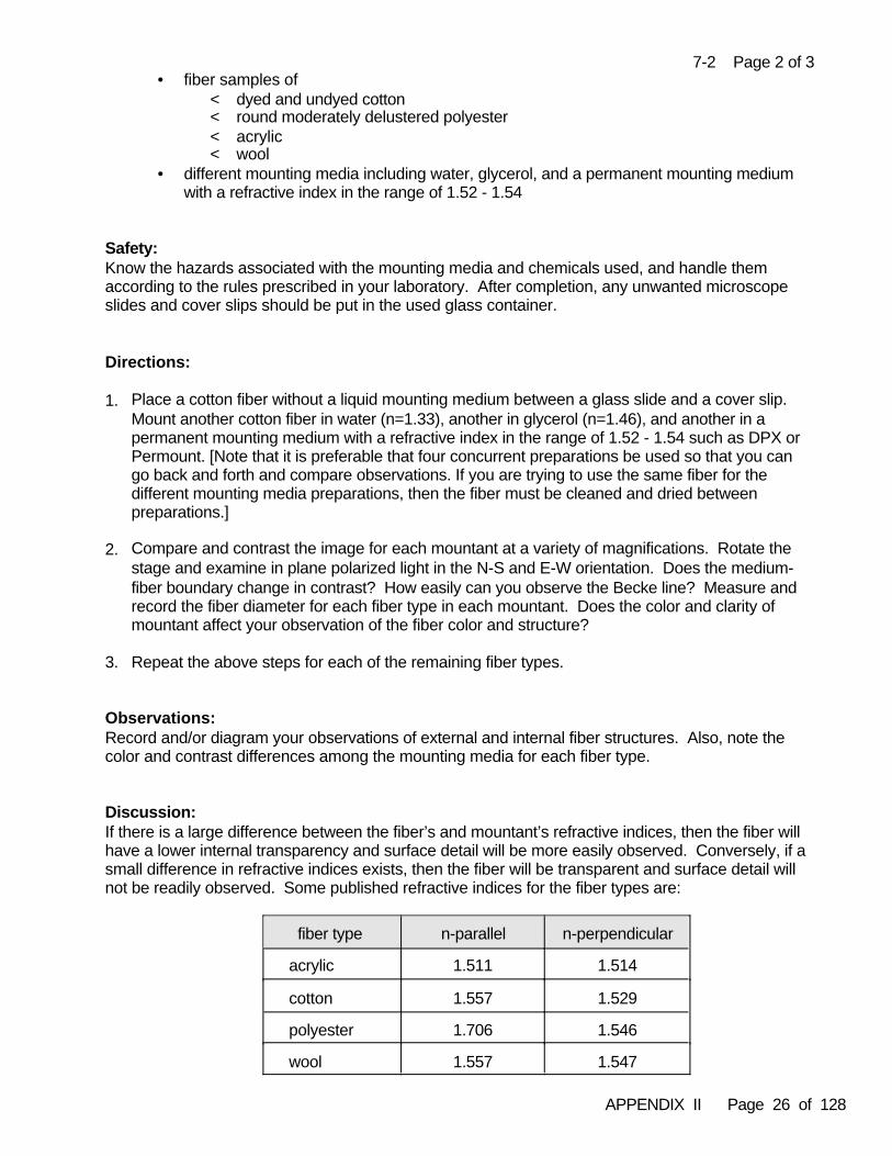
APPENDIX II Page 26 of 128
7-2 Page 2 of 3• fiber samples of
< dyed and undyed cotton< round moderately delustered polyester< acrylic < wool
• different mounting media including water, glycerol, and a permanent mounting mediumwith a refractive index in the range of 1.52 - 1.54
Safety:Know the hazards associated with the mounting media and chemicals used, and handle themaccording to the rules prescribed in your laboratory. After completion, any unwanted microscopeslides and cover slips should be put in the used glass container.
Directions:
1. Place a cotton fiber without a liquid mounting medium between a glass slide and a cover slip. Mount another cotton fiber in water (n=1.33), another in glycerol (n=1.46), and another in apermanent mounting medium with a refractive index in the range of 1.52 - 1.54 such as DPX orPermount. [Note that it is preferable that four concurrent preparations be used so that you cango back and forth and compare observations. If you are trying to use the same fiber for thedifferent mounting media preparations, then the fiber must be cleaned and dried betweenpreparations.]
2. Compare and contrast the image for each mountant at a variety of magnifications. Rotate thestage and examine in plane polarized light in the N-S and E-W orientation. Does the medium-fiber boundary change in contrast? How easily can you observe the Becke line? Measure andrecord the fiber diameter for each fiber type in each mountant. Does the color and clarity ofmountant affect your observation of the fiber color and structure?
3. Repeat the above steps for each of the remaining fiber types.
Observations: Record and/or diagram your observations of external and internal fiber structures. Also, note thecolor and contrast differences among the mounting media for each fiber type.
Discussion:If there is a large difference between the fiber’s and mountant’s refractive indices, then the fiber willhave a lower internal transparency and surface detail will be more easily observed. Conversely, if asmall difference in refractive indices exists, then the fiber will be transparent and surface detail willnot be readily observed. Some published refractive indices for the fiber types are:
fiber type n-parallel n-perpendicular
acrylic 1.511 1.514
cotton 1.557 1.529
polyester 1.706 1.546
wool 1.557 1.547
APPENDIX II Page 27 of 128
7-2 Page 3 of 3
For cotton you should have noted a dark band at the interface between fiber and air. The internalstructure cannot be seen. As you increase the refractive index, from water to glycerol to permanentmedia, transparency will increase and contrast at the interface will decrease. Cross-markings aremore easily seen in the higher refractive index liquids. With plane polarized light it is difficult to seethe difference between n-parallel and n-perpendicular when the sample is mounted in low refractiveindex liquids such as water and glycerol. The difference in the fiber refractive indices should beeasily observed when in a higher refractive index medium such as 1.52.
For wool you should have observed that there is less contrast at the medium-fiber interface as therefractive index of the mountant is increased. Scales are easily seen in the water mount. Therefractive index of glycerol (n~1.46) is too low compared to wool (n~1.55) to allow for anexamination of the interior of the hair, and the outside portion of the hair (scales) is more readilyobserved. Differences in n-parallel and n-perpendicular of the wool fiber can be discerned atrefractive indices close to that of the wool.
For the manufactured fibers you should have also observed changes in boundary contrast and fibertransparency based on the relative difference in refractive index. If the fibers are mounted in amedium with the same refractive index as the fiber, then the boundary contrast becomes zero andthe fiber seems to disappear. As transparency of the fiber is improved the internal structures suchas delusterant should have become more apparent. In exceedingly high boundary contrastsituations it may be difficult to see the Becke line and measure fiber diameter. A mountant withn~1.52 -1.54 should result in a very high contrast for the polyester fiber in the n-parallel position andless contrast in the n-perpendicular position. With some practice, the amount of boundary contrastcan be used to suggest how different the refractive index of the medium is from those of the fiber. This becomes useful when trying to identify a fiber generic class and selecting mounting media todetermine the fiber refractive indices. These concepts will be explored more in PracticalExercise 11-3.
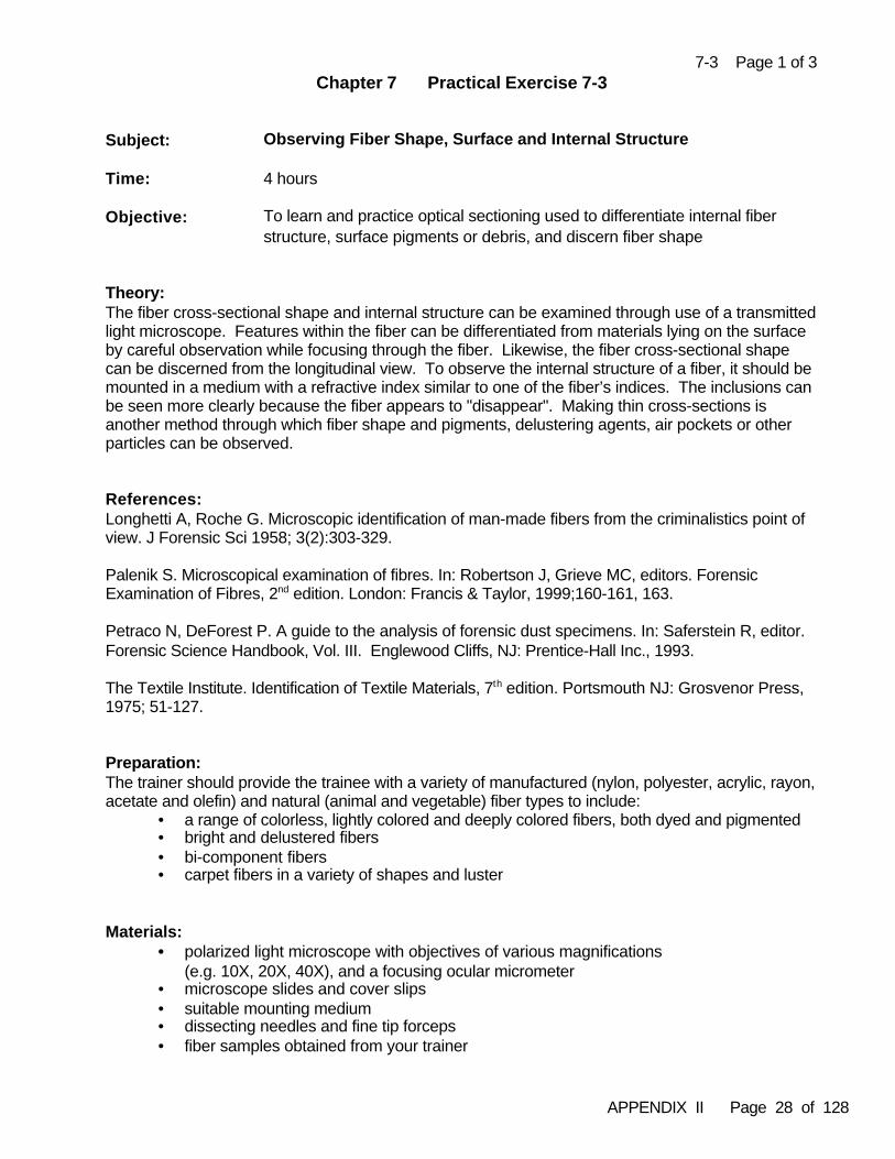
APPENDIX II Page 28 of 128
7-3 Page 1 of 3Chapter 7 Practical Exercise 7-3
Subject: Observing Fiber Shape, Surface and Internal Structure
Time: 4 hours
Objective: To learn and practice optical sectioning used to differentiate internal fiberstructure, surface pigments or debris, and discern fiber shape
Theory: The fiber cross-sectional shape and internal structure can be examined through use of a transmittedlight microscope. Features within the fiber can be differentiated from materials lying on the surfaceby careful observation while focusing through the fiber. Likewise, the fiber cross-sectional shapecan be discerned from the longitudinal view. To observe the internal structure of a fiber, it should bemounted in a medium with a refractive index similar to one of the fiber’s indices. The inclusions canbe seen more clearly because the fiber appears to "disappear". Making thin cross-sections isanother method through which fiber shape and pigments, delustering agents, air pockets or otherparticles can be observed.
References:Longhetti A, Roche G. Microscopic identification of man-made fibers from the criminalistics point ofview. J Forensic Sci 1958; 3(2):303-329.
Palenik S. Microscopical examination of fibres. In: Robertson J, Grieve MC, editors. ForensicExamination of Fibres, 2nd edition. London: Francis & Taylor, 1999;160-161, 163.
Petraco N, DeForest P. A guide to the analysis of forensic dust specimens. In: Saferstein R, editor.Forensic Science Handbook, Vol. III. Englewood Cliffs, NJ: Prentice-Hall Inc., 1993.
The Textile Institute. Identification of Textile Materials, 7th edition. Portsmouth NJ: Grosvenor Press,1975; 51-127.
Preparation: The trainer should provide the trainee with a variety of manufactured (nylon, polyester, acrylic, rayon,acetate and olefin) and natural (animal and vegetable) fiber types to include:
• a range of colorless, lightly colored and deeply colored fibers, both dyed and pigmented• bright and delustered fibers • bi-component fibers • carpet fibers in a variety of shapes and luster
Materials: • polarized light microscope with objectives of various magnifications
(e.g. 10X, 20X, 40X), and a focusing ocular micrometer• microscope slides and cover slips• suitable mounting medium• dissecting needles and fine tip forceps• fiber samples obtained from your trainer
APPENDIX II Page 29 of 128
7-3 Page 2 of 3
Safety:Know the hazards associated with the mounting media used and handle them according to the rulesprescribed in your laboratory. After completion, any unwanted microscope slides and cover slipsshould be put in the used glass container.
Directions:
1. Ensure that the ocular micrometer is properly calibrated for use at low, medium and highmagnifications, and that the microscope is adjusted for Köhler illumination. Mount the fibersusing Permount or other suitable mounting medium with a known refractive index of 1.50 + .05.
2. Begin by observing the mounted fiber under low magnification. Slowly focus up and downthrough the fiber in both parallel and perpendicular directions. Carefully observe the structuraldetail in each focal plane while focusing from the top surface of the fiber through to the bottomsurface of the fiber. Record your observations. In a like manner, observe the mounted fiberunder medium and high magnifications.
3. Repeat step 2 for all the fiber types.
Observations:Record and diagram your observations of each fiber type. Observations to make include notation of:
• any surface debris, pigment particles, fiber surface textures or other treatments• internal inclusions, voids, draw marks and striations • the amount, size, shape and distribution of each observed feature• mentally assemble the series of 2-dimensional focal plane images of the fiber surface
into a 3-dimensional cross-sectional shape
If you are unsure of what you are seeing, then try this as a starting point. Olefin fibers usually can’tbe dyed so if they are colored, then pigment is generally added to the polymer mixture during fiberproduction making these fibers likely candidates to observe pigment within the fibers. Olefin wouldalso be a good synthetic fiber to observe air pockets and any draw marks spreading from thosevoids.
Evaluate your observational skills with your trainer by comparing your observations of shape andstructure to those known or previously documented for the fiber samples you were given.
Discussion:The fiber cross-sectional shape and the amount, size, shape and distribution of the internalstructures or inclusions are important features used to identify and discriminate fibers. Duringmanufactured fiber production, pigments and delustrants may be added to the polymer solution.Internally pigmented fibers differ greatly from dyed and surface pigmented fibers. Voids anddelustrants may be confused at low power, but the properties of each can be discriminated andcompared at higher magnifications with careful focusing and observation. Draw marks andstriations are often easily apparent as part of the surface structure of the fiber. Fabric productionand finishing processes may result in visible fiber surface texture, pigmentation and other additives.
APPENDIX II Page 30 of 128
7-3 Page 3 of 3
The drawing of the polymer may produce internal structures and striations which can be seen underthe microscope as markings within the fiber. Pigment granules added for coloring the fiber mayhave air pockets surrounding them in the polymer solution. During drawing, air pockets maybecome elongated to appear like cones on either side of a pigment granule or agglomerate. Theseinclusions are in the fiber itself and are easily differentiated from outside debris and pigment lying onthe surface.
Voids are collapsed air spaces formed inside of the fiber during spinning. Draw marks, similar tothose which may appear from the air pocket surrounding pigment granules, may be formed fromvoids. These draw marks appear as "<0>" in melt spun fibers, sometimes called a fish eyebecause of the shape.
Many organic polymer manufactured fibers crystallize as spherulites. The crystals’ sphericalsymmetry elongates along the fiber axis when the fiber is drawn. Some spherulites, particularly inlarge denier nylon carpet fibers, may be large enough to be seen with the light microscope. Theywill appear as elongated streaks inside the fiber when viewed with the fiber in a longitudinal mount. If you have found any fibers with possible spherulites while performing this exercise, then you shouldretain them for further examination in physical cross section Practical Exercise 12-1.
Inclusions are relatively large objects added to the polymer mix before spinning. Pigments anddelustrants are the most prevalent forms of inclusions found in fibers. The most common delustrantis rutile titanium dioxide while a less common form is anatase titanium dioxide. Pigment observationand comparison includes the color of the pigment, which is a highly discriminating characteristic,and the size and shape of the granule or aggregate.
Become familiar with the longitudinal appearance of various cross-sectional shapes. Thesemounted and unmounted fiber samples should be retained and used in a self-study adjunct toPractical Exercise 12-1. This will be useful from two perspectives. First, you can re-examine thelongitudinal mounts and review your notes from this exercise. Hopefully you will demonstrate toyourself that your observational skills have improved over time and practice. Second, you canphysically cross section the unmounted samples and compare your longitudinal view observationsto the cross-sectional view as additional practice and experience.
APPENDIX II Page 31 of 128
7-4 Page 1 of 2Chapter 7 Practical Exercise 7-4
Subject: Observing Color and Pleochroism
Time: 3 hours
Objective: To observe dyed color and pleochroism in fibers
Theory: Textile fibers may be dyed or pigmented. Dyes are soluble materials that are incorporated intofibers by chemical reaction, absorption or dispersion. Pigments are insoluble, finely groundmaterials incorporated into the fiber polymer, or adhering to fibers’ exterior surfaces. About 8,000 dyes and pigments are available to the textile industry. Any one color is nearly always derivedfrom more than one dye. The range of colors possible in the textile industry is almost infinite,making color an important characteristic for discriminating between fibers of the same genericclass. Textiles are colored in batches and the variation between batches adds to the potentialsignificance of a fiber comparison.
Pleochroism is the phenomenon of an object displaying different colors depending upon itsorientation when viewed in polarized light. Of the manufactured fibers, only those which are highlyoriented have the capacity to display pleochroism. The dye molecules become aligned with thefibers' micelles and respond differentially to the vibrations of light in the two directions of light. Pleochroism may be called dichroism when referring to fibers because they have two optical axesand are, therefore, only capable of displaying two colors. The range of pleochroism may beanywhere from a slight change of color shade to completely different colors. Rayon, particularly,may exhibit almost no color in n-perpendicular and a deep color in n-parallel. It is important toobserve and record pleochroism in fiber examinations and comparisons because not all fibers arepleochroic, and of those that are, not all are pleochroic to the same degree.
References:Aspland JR. What are dyes? What is dyeing?. AATCC Dyeing Primer. Research Triangle Park,NC:American Association of Textile Chemists and Colorists, 1981.
Connelly RL. Colorant formation for the textile Industry. In: Color Technology in the Textile Industry,1997; 91-96.
Frei-Sulzer M. Coloured fibres in criminal investigation with special reference to natural fibers. In:Curry AS, editor. Methods of Forensic Science, Vol. IV. New York: Interscience Publishers Inc.1965;152-164.
Preparation: Obtain samples of colored natural and manufactured fibers to include as many generic types aspossible. Dyed fibers, pigmented fibers and printed textiles should be examined. Mount the fibersusing a suitable mounting medium.
APPENDIX II Page 32 of 128
7-4 Page 2 of 2Materials:
• polarized light microscope• microscope slides and cover slips• suitable mounting medium• dissecting needles and fine tip forceps• fiber samples
Safety:Know the hazards associated with the mounting media used and handle them according to the rulesprescribed in your laboratory. After completion, any unwanted microscope slides and cover slipsshould be put in the used glass container.
Directions: 1. Ensure that the microscope is properly set-up and adjusted for Köhler illumination.
2. Observe each fiber sample in whole mount under (non-polarized) transmitted light noting thefollowing:
• color of the fiber• uniformity of the color (even, cloudy, patchy, streaky, blotchy, etc)• whether the fiber appears dyed, pigmented, or printed• whether variations exist between the colors of the fibers in the same sample
3. View the same samples under polarized light (analyzer out) in the perpendicular and parallelorientations noting the following:
• the color of the fiber in each of the two orientations • the intensity of the color(s) in each of the two orientations• if any of the natural fibers exhibit pleochroism • if any differences in pleochroism exist between fibers of the same generic type and color,
or between differently colored fibers of the same generic type
Observations:Record your observations of each fiber type noting in particular the items listed in the Directions.
Discussion:Not all fibers accept the same dye(s) uniformly and the quality of the final textile product isdependent on hundreds of variables. This variability works in the fiber examiner's favor fordistinguishing between fibers that would otherwise appear similar. The goal of textile producers is tohave uniform products that fall within predetermined standards. Dyeing is one of the most variableprocesses in textile production. Natural fibers, in particular, exhibit variation in the uptake of certaindyes and this can lead to undesirable final products which are off-shade or even the wrong color. The main focus of the dyeing industry is to limit this variation as much as possible to repeatedlyyield a uniform product.
In general, manufactured fibers will take dyes more uniformly than natural fibers. This generalizationwas one of the motivating factors in the development of manufactured fibers.
Although natural fibers generally do not exhibit pleochroism, some dyed cottons and bast fibers do. Not all manufactured fibers exhibit pleochroism. In manufactured fibers, pleochroism is seen mostoften in highly oriented fibers such as rayon, nylon and polyester.
APPENDIX II Page 33 of 128
7-5 Page 1 of 3Chapter 7 Practical Exercise 7-5
Subject: Distinguishing Natural and Manufactured Fiber Classes
Time: 3 hours
Objective: To observe, compare and distinguish among the natural and manufacturedfibers by basic morphological features
Theory: Natural fibers come from organic renewable resources and can be broadly classified as animal, vegetable, or mineral in origin. Manufactured fibers are produced by extensive chemical andmanufacturing processes. Any of these fiber types may be found in textile products of forensicinterest. One of the first steps in a forensic fiber examination is for the fiber examiner to be able todistinguish between natural and manufactured fibers when they are viewed under the microscope.
Fibers of animal origin include hairs, silk, leather and spider silk. The most commonly encounteredanimal fibers of forensic interest are hairs. Hairs are recognized by the presence of surface scales,internal medullation, and the overall shape. Vegetable fibers can originate from any part of a plantincluding the stem or bast (e.g. flax, ramie, jute, hemp), leaf (e.g. sisal, manila hemp [= abaca,Musa textilis]), fruit (e.g. coir, kapok), and seed (e.g. cotton, akund). Many of the vegetable fibersthat are too coarse to be used in textiles are used in different types of cordage or consumerproducts such as doormats (coir) and various paper products. Vegetable fibers can be recognizedby the presence of cellulosic walls, features of the cell wall (dislocations, pits and spiralthickenings), various crystals, and the central cavity called a lumen. Compared to natural fibers,manufactured fibers are fairly uniform and regular in their microscopic appearance as a result of thematerials and processes used in manufacturing. Useful clues that a fiber is manufactured include:the absence of features typically associated with animal and vegetable fibers (i.e. no scales, no cellwalls), its cross-sectional shape and usually uniform shape, diameter and thickness along the fiberlength, the presence of interference color bands parallel to the long axis that only vary when the fiberis stretched or bent, and the presence of delustrant.
References:Carroll G R. Forensic fibre microscopy. In: Roberston J, editor. Forensic Examination of Fibres, 1st edition. London: Ellis Horwood Ltd.,1992; 99-105.
Gaudette B. The forensic aspects of textile fiber examination. In: Saferstein R, editor. ForensicScience Handbook, Vol. II. Englewood Cliffs, NJ: Prentice-Hall Inc., 1988; 211-213, 238-241.
Joseph ML. Introductory Textile Science, 3rd edition. New York: Holt, Rinehart and Winston, 1977;41-50, 88-111,184-187.
The Textile Institute. Identification of Textile Materials, 7th edition. Portsmouth NJ: Grosvenor Press,1975; 136.
Preparation: Obtain authenticated and commercial samples of natural and manufactured fibers to include: cotton(mercerized and unmercerized), flax, hemp, sisal, wool, silk, mohair, rabbit, suede, fiber glass,rayon, nylon and polyester. There should be colorless, dyed and/or pigmented representatives of
APPENDIX II Page 34 of 128
7-5 Page 2 of 3
each fiber type. The manufactured fibers should include bright and delustered representatives ofeach.
Materials: • stereomicroscope and polarized light microscope• microscope slides and cover slips• suitable mounting media• dissecting needles and fine tip forceps• fiber samples
Safety:Know the hazards associated with the mounting media used and handle them according to the rulesprescribed in your laboratory. After completion, any unwanted microscope slides and cover slipsshould be put in the used glass container.
Directions:
1. Ensure that the polarized light microscope is properly set-up and adjusted for Köhler illumination.
2. Place small quantities of one fiber type on a clean glass slide. Examine the fiber(s) under thestereomicroscope. Tease the fibers apart if necessary to obtain a clear view of theirmorphological features at this level of magnification. Record your observations.
3. Mount the fibers using a suitable mounting medium. Observe each fiber sample with planepolarized transmitted light and with crossed polars. As a minimum, you should examine eachfiber sample at 100X and 200X. Note the fiber’s gross morphological features as well as theinternal and external structures used to characterize the natural (animal and vegetable) versusmanufactured general categories. Record your observations.
4. Repeat steps 2 and 3 for each fiber sample.
Observations:Make a chart of the various features you can use to distinguish animal, vegetable, mineral andmanufactured fibers. Record your observations relative to these features for each fiber sample youexamined. Sketch the appearance of the fibers and features observed.
Discussion:Fibers can be screened and class categorized as natural (animal, vegetable, mineral) versusmanufactured by microscopical examination of the longitudinal view alone with time and practice. Differentiating among these groups is fairly straightforward if you are familiar with the variousmicroscopic characteristics each class of fiber possesses. It is the initial evaluation and grouping offibrous material in casework that helps determine which items are probative, and which analyticalschemes to pursue.
Caution should be used when examining fibers that have been heavily dyed or processed, such asmercerization, which could alter or obscure characteristic morphological features. Also, consider
APPENDIX II Page 35 of 128
7-5 Page 3 of 3
the level of magnification necessary to ensure you were clearly seeing the features necessary tocategorize the fiber. How many of the characteristic morphological features can you clearly see anddescribe when using the stereomicroscope? Can you categorize any of the fibers you examinedbased on the stereomicroscopic examination or is higher magnification necessary to confirm yourinitial observations? Is that true for all the fiber types you examined?
Silk is one fiber type that may present some observational confusion. Silk, a fiber of animal originthat is not a hair, will have a smooth appearance usually without visible internal structures, and hasinterference color bands parallel to the long axis. Silk may exhibit “cross-over marks” that areoblique flattened areas along the fiber, or may exhibit internal striated or granular appearancedepending on the type of silk you examined. Were there other fibers or fiber features that presentedobservational confusion?
In this particular exercise you may have started with fiber samples that contained multiple fibers ortufts of material. In casework material you cannot assume or rush to judge all fibers in the sampleto be similar without the appropriate level of examination.
APPENDIX II Page 36 of 128
8-1 Page 1 of 3Chapter 8 Practical Exercise 8-1
Subject: Microscopy of Non-woody Vegetable Fibers
Time: 8 hours
Objective: To learn microscopic features of bast, leaf and seed fibers used indifferentiation or identification of the source
Theory: Differentiation and identification of non-woody vegetable fibers is largely based on the recognition ofdistinguishing microscopic features of the fiber cells. Observations of the crystalline inclusions andthe morphological appearance of the cells in longitudinal and cross-sectional mounts can providesufficient discriminating and identifying features of these fiber types, whether the fiber cells occurindividually or grouped in bundles.
References:Catling D, Grayson J. Identification of Vegetable Fibres. London: Chapman and Hall, 1982.
The Textile Institute. Identification of Textile Materials, 7th edition. Portsmouth, NJ: Grosvenor Press1975;14-20, 74-91, 136-137, 167-170, 223-225.
Preparation: Obtain authenticated fiber samples of cotton, coir, flax, hemp, ramie, jute, sisal, henequen, andmanila hemp. Note that you will need a sufficient amount of fiber samples to use in this exercise aslongitudinal mounts and for cross-sectioning, and still have some unmounted fiber sample for use inPractical Exercise 8-2.
Materials: • stereomicroscope (for initial observation and mounting slides)• polarized light microscope with various objectives (e.g. 4X,10X, 20X, 40X and 100X) and
calibrated ocular micrometer• microscope slides and cover slips• suitable mounting medium• dissecting needles and fine tip forceps• fiber cross-sectioning supplies• authenticated fiber samples
Safety: Know the hazards associated with the mounting media used and handle them according to the rulesprescribed in your laboratory. After completion, any unwanted microscope slides and cover slipsshould be put in the used glass container. Use caution when using razor blades and place usedblades in a sharps disposal container.
APPENDIX II Page 37 of 128
8-1 Page 2 of 3
Directions:
1. Prepare longitudinal mounts of the known fiber samples by mounting several (~ two centimeterslong) fiber strands of each on microscope slides using Permount or another appropriatemounting medium (i.e. XAM). Some of the “fibers” will actually be bundles of multiple cells andmay require teasing of the sample to obtain a reasonable microscopic mount for properobservations.
2. Examine each fiber sample in longitundinal mount. Note:• the presence or absence of transverse dislocations• the longitudinal variation in the cell wall thickness and lumen dimension• the fiber cell wall and lumen diameters• the relative size of the lumen compared to the fiber diameter• whether the cells readily separate out of the bundles, or not• shape of the cell tips• the presence of any other striations, markings, pits or spiral cell wall thickenings• the presence, shape and position of crystalline inclusions [Note that some crystalline
inclusions are more readily visible with crossed polars.]
3. Record your observations for each fiber type.
4. Compare and contrast your observations for each fiber type. Can you or can you not distinguishamong all of the fiber types by longitudinal observations? Re-examine each fiber sample inlongitudinal mount from the perspective of comparing and contrasting among the samples. Save your longitudinal mounts for use in Practical Exercise 8-2.
5. Prepare acceptable cross sections of each fiber type and mount them for microscopicalexamination.
6. Examine each of the fiber types in cross section with at least 200X magnification. Note:• how each of the features viewed in longitudinal mount appear in cross section• the thickness of the cell and the cell wall relative to the lumen size and shape• cross-sectional shape of the single fiber cells (=ultimates)• presence of any radial cracks in the cell wall• how the ultimates are arranged within the bundles• variation of ultimates within the fiber bundles of the same plant species
7. Record and diagram your observations and differentiate the samples based on the featuresrevealed in the cross sections.
Observations:Prepare a table of observed morphological features for each fiber type including appropriatediagrams for both the longitudinal and cross-sectional views. Re-examine the fiber samplescomparing and contrasting morphological features. Specifically identify any morphological featuresthat:
• differentiate the bast, leaf or seed fiber types as to their plant part origin• would allow discrimination or segregation among fibers with similarly appearing features• are sufficiently distinctive for identification of a particular fiber type
APPENDIX II Page 38 of 128
8-1 Page 3 of 3
Discussion:Vegetable fibers encountered in forensic casework can originate from a variety of end use productsincluding cordage, burlap bags, carpet backing, and clothing articles. Some of the most commonlyencountered vegetable fibers originate from textile articles composed of cotton, ramie, flax andhemps.
Microscopical observation of plant cell cross sections and longitudinal mounts should be used inconjunction with microchemical methods to identify vegetable fibers. Bast fibers (ramie, flax, jute,hemp, kenaf, roselle, sunn hemp, urena) originate from the plant stem vascular tissue (phloem andxylem) and have microscopically distinctive structures characteristic of the tissue and of the plantwhen seen in longitudinal view. However, discrimination among these fibers is perhaps betteraccomplished with the best-view observation of the plant cell wall and lumen in prepared crosssections. Particularly important are the shape of the fiber bundles, shape of the cells, size andshape of the cell lumen, size of lumen relative to the overall cell size, and thickness of the cell wall.
As technical fibers, flax, ramie and jute are examples of fiber types that may appear similar inlongitudinal mount, but can be differentiated by observation of the cross section. Ramie fiberultimates are thick walled with slit-like lumina, and have flattened oval cross-sectional shapes. Flaxfiber ultimates are very thick walled with very small rounded lumina, and have polygonal cross-sectional shapes. Jute fiber ultimates appear similar to flax fibers except that jute fibers have largerrounded lumina.
Distinctive crystals are often visible in longitudinal mounts making destructive ashing of samplesunnecessary. Sisal, henequen and manila hemp may appear very similar morphologically, butsome discrimination is possible based upon crystalline inclusions. Sisal and henequen have similarfusiform shaped crystals usually occurring singly, while manila has silica-based crystals ofrectangular shape with a peripheral central depression usually occurring in multiples along a row.
The trainee is encouraged to examine more of the vegetable fiber types than were specificallycovered in this exercise, and to examine dyed or pigmented fiber samples. Familiarity andexperience of the examiner with the observation of the microscopical features of vegetable fibers arethe primary analytical tools used for fiber discrimination and identification. There can be significantvariation within some of the fiber types due to the inherent variability of a natural source fiber, anddifferences in the quality controls in fiber preparation or manufacturing processes. In addition,possible artifacts can be caused by manufacturing processes (e.g. commercial bleaching,mercerization) or poor sample preparation (e.g. incomplete mountant infiltration, fiber bundlecompression distortions during cross-sectioning).
APPENDIX II Page 39 of 128
8-2 Page 1 of 3Chapter 8 Practical Exercise 8-2
Subject: Determining Natural Fiber Twist
Time: 3 hours
Objective: To learn the Herzog effect and the drying twist test
Theory: Vegetable fiber cell walls are composed of parallel microfibrils running in a longitudinal spiral. Thesefibers can be categorized according to the direction of fibril twist. Fibers having a left-hand twist(e.g. flax and ramie) are designated as having an “S-twist”. Conversely, fibers having a right-handtwist (e.g. hemp, jute and sisal) are referred to as having a “Z-twist”. The direction of twist can beascertained through the use of polarized light microscopy or by the drying twist test.
Identification of vegetable fibers is accomplished primarily through the recognition of distinguishingbotanical characteristics that are unique to a particular type of vegetable fiber. Unfortunately, somevegetable fiber types exhibit similar gross botanical characteristics thereby making theiridentification more difficult. Differentiation of vegetable fibers which have similar gross botanicalfeatures may be accomplished by observing the effect the fiber has on polarized light, referred to asthe Herzog effect, as a result of the differences in their microfibril orientation. Interference colors areobserved when vegetable fibers are examined between crossed polars. These colors result fromthe destructive interference of light waves of certain wavelengths and their consequent removal fromwhite light. When a first order red compensator (~530 nm) is inserted into the microscope betweenthe fiber sample and the analyzer, the resultant change in the interference colors displayed by thefiber will be additive or subtractive because of the microfibril orientation.
References:Carroll GR. Forensic fibre microscopy. In: Robertson J, editor. Forensic Examination of Fibres, 1st edition. London: Ellis Horwood Ltd., 1992; 101-102.
DeForest PR. Foundations of forensic microscopy. In: Saferstein R, editor. Forensic ScienceHandbook, Vol. I. Englewood Cliffs, NJ: Prentice-Hall Inc., 1982; 487-488.
The Textile Institute. Identification of Textile Materials, 7th edition. Portsmouth, NJ: Grosvenor Press1975;168-169, 225.
Valaskovic GA. Polarized light in multiple birefringent domains: a study of the Herzog effect. TheMicroscope 1991; 39:269-286.
Preparation: You should use remaining unmounted fiber samples and the longitudinal mounts of fibers preparedin Practical Exercise 8-1. If the mounted samples are no longer available or could be improved, thenprepare new longitudinal mounts of authenticated fiber samples of cotton, coir, flax, hemp, ramie,jute, sisal, henequen, and manila hemp.
APPENDIX II Page 40 of 128
8-2 Page 2 of 3
Materials:• stereomicroscope (for initial observation and mounting slides)• polarized light microscope with various objectives (e.g. 4X,10X, 20X, 40X and 100X)• first order red plate (530-570 nm compensator)• microscope slides and cover slips (if new slide mounts are made)• suitable mounting medium (if new slide mounts are made)• dissecting needles and fine tip forceps• hot plate and beaker of warmed water• authenticated fiber samples, mounted and unmounted
Safety: Know the hazards associated with the mounting media used and handle them according to the rulesprescribed in your laboratory. After completion, any unwanted microscope slides and cover slipsshould be put in the used glass container. Use caution when holding material over the hot plate.
Directions:
Part 1 - The Herzog Effect
1. Place the mounted fiber sample on the microscope stage between crossed polars. 2. Orient the longitudinal axis of the fiber ultimate parallel to the vibration direction of the analyzer.3. Insert the compensator plate into the microscope between the sample and the analyzer.4. Observe and record the resultant color of the fiber ultimate. It should be either orange or blue.5. Repeat steps 1-4 for each of the mounted fiber samples.
Part 2 - The Drying Twist Test
1. Take a sample of unmounted fiber, large enough to be seen visually, and place it in the beaker ofwarm water. Note that too large of a fiber bundle can result in equivocal results. Someexperimentation may be needed to determine optimal sample size.
2. Remove the fiber from the water bath by holding one end with forceps, directing the other endtoward you as an axial view, over and near the hot plate heated surface.
3. As the fiber dries note whether it rotates clockwise, counterclockwise or has some otherresponse.
4. Record the drying rotation observation and relate it to the observed Herzog effect.
Observations:The resultant color of the fiber should be either orange or blue. The S-twist fibers will demonstratean additive effect, having a second order blue appearance. The Z-twist fibers will demonstrate asubtractive effect, having a first order orange appearance. Record the axial view rotation directionfor each fiber during the drying twist test. Compare and contrast the drying twist test and Herzogeffect observations.
Discussion:Vegetable fibers are identified primarily through a microscopical examination of morphologicalcharacteristics. Some vegetable fibers have distinctive botanical features that can be consideredunique thus leading to discrimination and identification of the fiber type. Other vegetable fibers

APPENDIX II Page 41 of 128
8-2 Page 3 of 3
have observable features that are less discriminating. The twist of these natural fibers is anothercharacteristic which can be used to characterize and/or identify the type or origin. The microfibrilstructure and direction of twist is not directly observable by transmitted light microscopy. TheHerzog effect observed with polarized light and the drying twist tests are methods by which themicrofibril twist can be indirectly observed and deduced. In some instances this allows the analystto differentiate between two vegetable fibers with similar microscopical appearances but differentbotanical origins.
The Herzog effect and drying twist test are simple, inexpensive and nondestructive methods thatcan be used in conjunction with other botanical identification characteristics for differentiatingbetween similar types of vegetable fibers. Neither test should be considered definitive foridentification purposes. Some authors have warned that the drying twist test observed results canbe influenced by fiber finishing processes, and observation of the Herzog effect works best withundyed fibers. The literature reports the following fiber twists:
S Twist Fibers Z Twist Fibers
flax hemp
ramie jute
coir sisal
manila hemp
henequen
Were your observations in both tests consistent with these reported data? Note that cotton exhibitsboth S and Z twist characteristics.
APPENDIX II Page 42 of 128
Page 1 of 3Chapter 9 Practical Exercise 9-1
Subject: Examining the Cuticle of Animal Hairs
Time: 8 hours
Objective: To learn scale casting and counting techniques used in the examinationof animal hair cuticles
Theory: Natural fibers of animal origin that are typically used in textile products include the animal hairsreferred to as the under hairs (as opposed to guard hairs), the specialty furs, silk and leather. Detailed microscopical examination of the morphological features is the basic analytical tool usedfor identification of these natural fiber types.
For the examination of fibers that are of animal hair origin, the cuticular scales are examined forscale margin appearance, scale margin distance and scale pattern. Scale margin appearance andscale pattern are the physical appearance or characterization of the scale shapes. Scale margindistance is the physical separation of the scales, determined by counting the number of scalespresent on a hair for a given length.
Examining cuticular scales can be accomplished by mounting the hairs in a medium with arefractive index that allows visualization of the hair exterior (but hinders the examination of the hairinterior structures), or by scale casting. Two commonly employed casting techniques use eitherclear fingernail polish or Polaroid film coater as the replicating medium.
References:Bruner H, Coman B. The Identification of Mammalian Hair. Melbourne:Inkata Press, 1974; 1-18.
Ogle RR, Mitosink BA, Mitosinka GT. A rapid technique for preparing hair cuticular scale casts. J Forensic Sci 1973;18:82.
Petraco N. The replication of hair cuticle scale patterns in meltmounts. The Microscope 1986; 34:341-345.
Petraco N. A microscopical method to aid in the identification of animal hair. The Microscope 1987;35:83-92.
Robertson J. Protocols for fibre examination and initial preparation. In: Robertson J, Grieve MC,editors. Forensic Examination of Fibres, 2nd edition. London: Francis & Taylor, 1999; 128-133.
Preparation: Calibrate the ocular micrometer for the microscope and objectives that you will be using if this hasnot already been done.
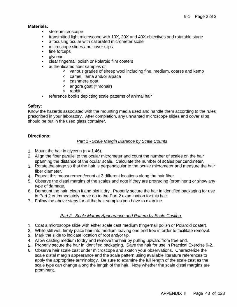
APPENDIX II Page 43 of 128
9-1 Page 2 of 3
Materials: • stereomicroscope • transmitted light microscope with 10X, 20X and 40X objectives and rotatable stage• a focusing ocular with calibrated micrometer scale• microscope slides and cover slips• fine forceps• glycerin• clear fingernail polish or Polaroid film coaters• authenticated fiber samples of
< various grades of sheep wool including fine, medium, coarse and kemp< camel, llama and/or alpaca< cashmere goat< angora goat (=mohair)< rabbit
• reference books depicting scale patterns of animal hair
Safety:Know the hazards associated with the mounting media used and handle them according to the rulesprescribed in your laboratory. After completion, any unwanted microscope slides and cover slipsshould be put in the used glass container.
Directions: Part 1 - Scale Margin Distance by Scale Counts
1. Mount the hair in glycerin (n = 1.46). 2. Align the fiber parallel to the ocular micrometer and count the number of scales on the hair
spanning the distance of the ocular scale. Calculate the number of scales per centimeter. 3. Rotate the stage so that the hair is perpendicular to the ocular micrometer and measure the hair
fiber diameter. 4. Repeat this measurement/count at 3 different locations along the hair fiber. 5. Observe the distal margins of the scales and note if they are protruding (prominent) or show any
type of damage.6. Demount the hair, clean it and blot it dry. Properly secure the hair in identified packaging for use
in Part 2 or immediately move on to the Part 2 examination for this hair.7. Follow the above steps for all the hair samples you have to examine.
Part 2 - Scale Margin Appearance and Pattern by Scale Casting
1. Coat a microscope slide with either scale cast medium (fingernail polish or Polaroid coater). 2. While still wet, firmly place hair into medium leaving one end free in order to facilitate removal. 3. Mark the slide to indicate location of root and/or tip.4. Allow casting medium to dry and remove the hair by pulling upward from free end. 5. Properly secure the hair in identified packaging. Save the hair for use in Practical Exercise 9-2.6. Observe hair scale cast under microscope and sketch your observations. Characterize the
scale distal margin appearance and the scale pattern using available literature references toapply the appropriate terminology. Be sure to examine the full length of the scale cast as thescale type can change along the length of the hair. Note whether the scale distal margins areprominent.
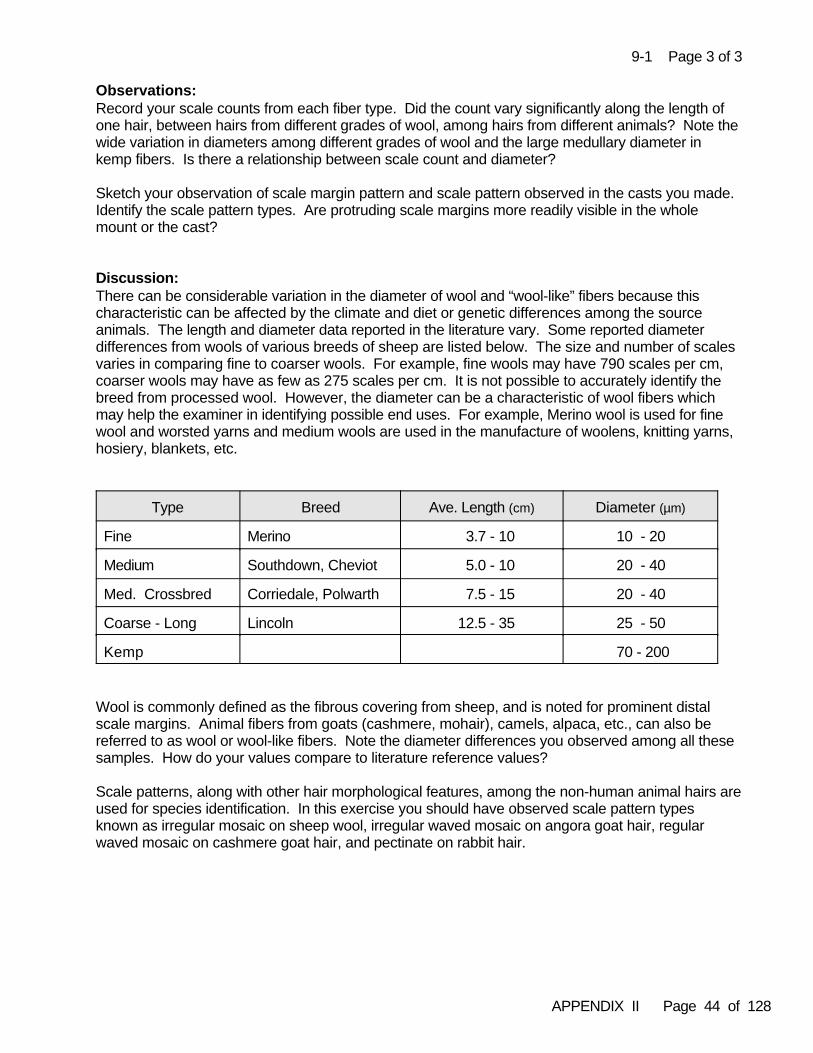
APPENDIX II Page 44 of 128
9-1 Page 3 of 3 Observations:Record your scale counts from each fiber type. Did the count vary significantly along the length ofone hair, between hairs from different grades of wool, among hairs from different animals? Note thewide variation in diameters among different grades of wool and the large medullary diameter inkemp fibers. Is there a relationship between scale count and diameter?
Sketch your observation of scale margin pattern and scale pattern observed in the casts you made. Identify the scale pattern types. Are protruding scale margins more readily visible in the wholemount or the cast?
Discussion:There can be considerable variation in the diameter of wool and “wool-like” fibers because thischaracteristic can be affected by the climate and diet or genetic differences among the sourceanimals. The length and diameter data reported in the literature vary. Some reported diameterdifferences from wools of various breeds of sheep are listed below. The size and number of scalesvaries in comparing fine to coarser wools. For example, fine wools may have 790 scales per cm,coarser wools may have as few as 275 scales per cm. It is not possible to accurately identify thebreed from processed wool. However, the diameter can be a characteristic of wool fibers whichmay help the examiner in identifying possible end uses. For example, Merino wool is used for finewool and worsted yarns and medium wools are used in the manufacture of woolens, knitting yarns,hosiery, blankets, etc.
Type Breed Ave. Length (cm) Diameter (µm)
Fine Merino 3.7 - 10 10 - 20
Medium Southdown, Cheviot 5.0 - 10 20 - 40
Med. Crossbred Corriedale, Polwarth 7.5 - 15 20 - 40
Coarse - Long Lincoln 12.5 - 35 25 - 50
Kemp 70 - 200
Wool is commonly defined as the fibrous covering from sheep, and is noted for prominent distalscale margins. Animal fibers from goats (cashmere, mohair), camels, alpaca, etc., can also bereferred to as wool or wool-like fibers. Note the diameter differences you observed among all thesesamples. How do your values compare to literature reference values?
Scale patterns, along with other hair morphological features, among the non-human animal hairs areused for species identification. In this exercise you should have observed scale pattern typesknown as irregular mosaic on sheep wool, irregular waved mosaic on angora goat hair, regularwaved mosaic on cashmere goat hair, and pectinate on rabbit hair.
APPENDIX II Page 45 of 128
9-2 Page 1 of 4Chapter 9 Practical Exercise 9-2
Subject: Introduction to Examining Natural Fibers of Animal Origin
Time: 12 hours (Part 1 ~8 hrs, Part 2 ~4 hrs)
Objective: To learn the basic morphological and optical features used to discriminateand identify the natural fibers of animal origin
Theory: Natural fibers of animal origin that are typically used in textile products include the animal hairsreferred to as the under hairs (as opposed to guard hairs), the specialty furs, silk and leather. Detailed microscopical examination of the morphological features is the basic analytical tool usedfor identification of the fiber types which originate from animal hairs. Determination of the opticaland physical properties is the basic analytical tool used for discrimination and identification of silkand leather.
All mammalian hair has three basic morphological components: the cuticle, the cortex and themedulla. Hair is primarily composed of the protein keratin and is considered a staple fiber. Once afiber is recognized as a hair, the next task is to determine if the hair is of human or non-humanorigin. The distinction between human and non-human hairs as well as species of origin among thenon-human hairs is made based on the detailed examination and characterization of all of themorphological components.
Silk and leather originate as protein secretions from animals and, therefore, are not hairs. Silk iscomposed of the protein fibroin and leather is composed primarily of the protein collagen. Thesetwo fiber types of animal origin are typically identified by their optical and physical propertiesobserved with polarized light microscopy and cross-sectional shape.
References:Bruner H, Coman B. The Identification of Mammalian Hair. Melbourne:Inkata Press, 1974; 1-18.
Hicks J. Microscopy of Hairs: A Practical Guide and Manual. Washington DC: FBI, 1977; 1-5, 28-40.
Palenik S. Light microscopy of medullary micro-structure in hair identification. The Microscope 1983;31:129-136.
Robertson J. Protocols for fibre examination and initial preparation. In: Robertson J, Grieve MC,editors. Forensic Examination of Fibres, 2nd edition. London: Francis & Taylor, 1999; 128-133.
Preparation: Calibrate the ocular micrometer for the microscope and objectives that you will be using if this hasnot already been done. This exercise assumes that the trainee can identify the basic structuralfeatures of hair and has an understanding of the characteristics used to distinguish human fromnon-human hair. It should be noted that for some hairs, infiltration of the mounting media may beslow. If you are working with hairs in which this appears to be the case, then it may be necessary toallow the preparations to sit for an extended period of time, continuing with the microscopical examination on another day.
APPENDIX II Page 46 of 128
9-2 Page 2 of 4Materials:
• stereomicroscope• polarized light microscope with 10X, 20X and 40X objectives and rotatable stage• a focusing ocular with calibrated micrometer scale• microscope slides and cover slips• adhesive tape• fine forceps• hot plate• glycerin• glycerin-alcohol mix (65:35)• scale casting supplies• fiber cross-sectioning supplies• mounting media with n~1.52-1.54• authenticated fiber samples of:
< various grades of sheep wool including fine, medium, coarse and kemp< camel, llama and/or alpaca< cashmere goat< angora goat (=mohair)< rabbit< any specialty fur hairs that your agency or environment is likely to encounter< human head hair and pubic hair< gummed and de-gummed silk (wild and cultivated types)< suede leather fibers
• reference books depicting animal hair structures and morphology of cuticle, cortex andmedulla
Safety:Know the hazards associated with the mounting media used and handle them according to the rulesprescribed in your laboratory. Use appropriate safety precautions when working with sharps and thehot plate. After completion, any unwanted microscope slides and cover slips should be put in theused glass container and used razor blades should be discarded in sharps disposal.
Directions: Part 1 - Examining Animal Hairs
1. Examine each hair with a stereomicroscope. Identify and characterize the root, shaft, shield, tip,overall profile and curl, and color banding. Measure the hair length for complete hairs.
2. Examine each hair cuticle by the methods learned in Practical Exercise 9-1 for those hairswhich you did not previously examine in that exercise. If your preparations in Practical Exercise9-1 could be improved upon, then make new scale casts as these may be kept in your personalcollection for later reference.
3. Mount each hair longitudinally in an appropriate medium with n~1.52-1.54. Observe the root,shaft, shield, tip and coloration along the length of the hair at higher magnification. Characterizethe medullary features along the length of the hair, such as size, form or type, and pigmentation. Characterize the cortical features along the length of the hair, including size, texture and pigmentation.
4. For each hair type you have (each species of origin), take another hair and clear the medulla bysplitting the hair and mounting in glycerin/alcohol according to the instructions found in Palenik,1983.
5. Compare and contrast the morphological features visible in the cleared hair with observablefeatures in the uncleared hair.
APPENDIX II Page 47 of 128
9-2 Page 3 of 4
Part 2 - Examining Silk and Leather
1. Observe and characterize the appearance of each fiber type with a stereomicroscope.2. Mount each fiber type longitudinally in an appropriate medium with n~1.52-1.54.3. Examine each fiber type by transmitted light microscopy and characterize the fiber color, shape,
surface and internal structure by optical sectioning. Measure the fiber diameter. (Recall thepreliminary observational techniques you learned in Practical Exercises 7-3 and 7-4.)
4. Examine each fiber type by polarized light microscopy and characterize their optical properties(refractive index, birefringence and sign of elongation) utilizing skills learned in Practical Exercise6-3, and found in Practical Exercises 11-1, 11-2 and 11-3.
5. Cross section each fiber type, mount the sections and observe the cross-sectional shape, size,internal structure and surface materials. (Refer to techniques found in Practical Exercise 12-1.)
Observations:Record and diagram your observations for each animal hair. Using appropriate reference literatureapply the correct terminology to each of the characterizations. Knowing the species of origin, doyour observations match illustrations from the literature used to typify hair fibers from thoseanimals?
Record your observations of the optical and physical properties of silk and leather. Although theseare considered natural fibers, their examination is similar to what you have learned for the characterization of manufactured fiber optical and physical properties. How do your observationaldata compare to published data for these fiber types?
Discussion:Familiarity with the longitudinal view of animal hair morphological features, and the optical/physicalproperties of silk and leather will often suffice for the rapid categorization and generic identification ofthese natural fiber types for the most commonly encountered textile products. Keratin, fibroin andcollagen will produce characteristic infrared spectra but they are not species specific.
Although this training program emphasizes fibers associated with textile products, reality is thatmost fiber examiners will encounter animal hairs in casework as associative trace evidence whichoriginate from common wild and domestic animals. The identification of species of origin requiressubstantial additional exposure to animal hair identification methods and taxonomy, and is usuallyconsidered a sub-specialty area of expertise. As time permits, the trainee can continue to examineanimal hairs, and to explore the information revealed by physical cross sections.
Silk is usually recognized by its characteristic optical properties, rounded deltoid cross section, lackof visible internal structure, and presence of surface cross-over marks. Leather originates from thepart of animal skin known as the dermis. Dermis is composed of bundles of collagen fibers whichare very low birefringent fibers. The dimensions and orientations of these fibers varies with theanimal species of origin, the somatic site of origin, and even environmental stress that the siteunderwent during and after the fiber deposition. Collagen fibers are not cells. Collagen is arepeating protein structure so there may be faint transverse striations visible on the fibers due to the molecular organization. In some animals there may be strands of skeletal muscle extending intothe dermis which remain in the leather product. These muscle fibers may appear microscopicallysimilar or indistinguishable to collagen to the untrained observer, but they are in fact different. Thesemuscle fibers also have a transverse banding pattern originating from the molecular alignments formuscle contraction.
APPENDIX II Page 48 of 128
9-2 Page 4 of 4
Any natural fibers of animal origin may be artificially dyed or pigmented, or may receive otherprocessing for use in textile products. These treatments, as with any other natural or manufacturedfiber type, are also subject to characterization, identifications and/or comparisons.
APPENDIX II Page 49 of 128
10-1 Page 1 of 3Chapter 10 Practical Exercise 10-1
Subject: Identification of Asbestos Fibers
Time: 4 hours
Objective: To learn to identify different types of asbestos fibers by using polarized lightmicroscopy with dispersion staining and other optical techniques, and tolearn to distinguish asbestos from other fibrous materials used in insulation,construction, textiles and papers
Theory: Most natural and manufactured fibers can be conclusively identified and distinguished from oneanother based upon their morphological and optical properties as examined using a polarized lightmicroscope. Among the optical properties that can be used to identify and distinguish fibers arerefractive indices, birefringence, sign of elongation, extinction, pleochroism and dispersion stainingcolors. The various types of asbestos (which include a number of naturally occurring fibrousmineral silicates) are readily identified in bulk samples by polarized light microscopy, particularlywhen used in conjunction with dispersion staining.
References:Deer WA, Howie RA, Zussman J. An Introduction to the Rock-Forming Minerals. New York: Addison-Wesley Publishing, 1992. [Note: read sections on asbestiform minerals; specific pagesvary in different editions.]
McCrone WC. Asbestos Identification, 2nd edition. Chicago: McCrone Research Institute, 1987.
McCrone WC, McCrone LB, Delly JB. Polarized Light Microscopy. Chicago: McCrone ResearchInstitute, 2002; 169-196.
Preparation: Before performing dispersion staining examinations on the asbestos reference materials, it may beuseful for the trainee to practice judging dispersion staining colors using known isotropic materialsfor which dispersion curves are available.
Materials: • stereomicroscope• polarized light microscope, dispersion staining objective, dispersion staining color chart• forceps, glass slides, cover slips, • high dispersion refractive index oils (including 1.550, 1.605 and 1.680)• authenticated standards of asbestos, other natural and manufactured fibers and
building/insulation materials. The following standards should be available:< Asbestos Materials: Crocidolite, chrysotile, amosite, fibrous tremolite, fibrous
actinolite, fibrous anthophyllite< Natural and manufactured fibers: Cotton, leather, paper, polyethylene
(pulped), Kevlar (pulped), glass wool, mineral wool, refractory ceramic fibers,Ryton (polyphenylene sulfide), other manufactured textile fibers as needed
< Other Fibrous Mineral Materials: Brucite, wollastonite, talc

APPENDIX II Page 50 of 128
10-1 Page 2 of 3
Safety:Asbestos samples and materials known to contain asbestos fibers should be handled and preparedin a hood with sufficient airflow to prevent the introduction of asbestos fibers into the laboratoryenvironment. Trainees should be familiar with the proper procedures before attempting to mountthese fibrous materials.
Directions:
1. Prepare microscopical mounts of known asbestos materials, as well as other standards ofsynthetic fibers and fibrous mineral materials. Use oils of one or more refractive indices, suchas 1.53 or 1.55.
2. Examine the morphological characteristics of each type of fiber and note the features that tendto distinguish asbestos fibers from most other types:
a. the presence of fiber bundles of widely varying diameters; and b. fiber ends which tend to fray down to individual fibrils smaller than 1 µm in diameter.
Also note differences in optical properties such as refractive indices relative to the mountant,birefringence and sign of elongation.
3. Prepare mounts of each of the six asbestos materials in high dispersion refractive index oils withindices of 1.550, 1.605 and 1.680. Observe each sample using the dispersion staining objective(central stop) with fibers oriented both parallel and perpendicular to the polarizer.
Using the dispersion staining color chart as a reference, record the colors observed in theparallel and perpendicular positions for each asbestos fiber type in each mountant. Note that forsome of the sample preparations, the matching wavelength for the fibers and oil will be welloutside the visible region, giving either black or very pale dispersion staining colors.
Perform the same observations for any of the fibrous mineral materials or other references thatwere difficult to distinguish from asbestos by normal PLM examination.
4. Compare the dispersion staining colors that you recorded for the samples to those listed inTable XIV, p 127, in Asbestos Identification. If your recorded colors differ from those in theTable, then re-examine your samples and the dispersion staining color chart. It may take somepractice to properly judge the colors.
5. When you are satisfied that you can correctly judge the parallel and perpendicular dispersionstaining colors for each asbestos sample, work through the Analytical Scheme for Asbestossupplied on page 157 of Asbestos Identification with each sample, until you are able todistinguish each of the six types. Alternatively, the condensed flowchart on page 167 for abestosidentification or another appropriate analytical scheme may be used.
6. Have your trainer prepare a series of unknown samples from the asbestos and other referencesets. Using the asbestos identification flowcharts and your experience from examining thereference samples, identify each unknown.
Observations:The manufactured fibers that are most likely to be confused with asbestos based on morphology arepulped polyethylene and pulped Kevlar. Leather may also be confused with asbestos. The traineeshould be familiar with the features that distinguish these fibers from asbestos. The differences in
APPENDIX II Page 51 of 128
10-1 Page 3 of 3
optical properties such as refractive indices relative to the mountant, birefringence and sign ofelongation should generally serve to fully distinguish asbestos fibers from all other fiber types.
Discussion:Having completed this exercise, the trainee should be capable of determining whether a fibroussample contains asbestos or other types of natural or manufactured fibers. The trainee should alsobe capable, if necessary, of determining what particular type(s) of asbestos fibers are present. Theidentification of specific asbestos types may be important in comparing evidence samples ofinsulation material, old textile products or the few textile products in which chrysotile may currentlyoccur.
APPENDIX II Page 52 of 128
11-1 Page 1 of 4Chapter 11 Practical Exercise 11-1
Subject: Determining the Sign of Elongation
Time: 4 hours (Part 1 ~2 hrs, Part 2 ~2 hrs)
Objective: To learn simple techniques for determining the sign of elongation of amanufactured fiber using a first order red plate or a quartz wedge
Theory: Polarized light is limited to a single vibration direction for any position of the polarizer. A crystal canbe oriented so that a particular crystallographic direction is parallel to the vibration direction of thepolarized light. The elongation of a manufactured fiber depends on the orientation of the moleculesalong its length. If the refractive index for light polarized parallel to the fiber length exceeds that forlight polarized perpendicular to the fiber length, then the elongation is said to be positive. If thereverse is true, then the fiber is said to have negative elongation. If the two refractive indices aredetermined by an immersion technique using liquids of known refractive index, then the sign can bedetermined by subtraction (n-parallel minus n-perpendicular). The sign of elongation can also bedetermined by inserting a compensator into the optical path of a polarized light microscope betweenthe specimen and the analyzer. Determining the sign of elongation is the first step toward establishing fiber identity.
Compensators are made from anisotropic crystalline material. That is to say, they have differentrefractive indices for light passing through them parallel and perpendicular to the crystal axes. Theslow direction will be that with the greater refractive index, and is usually marked as the “z” ray onthe body of the compensator. The compensators are inserted in the microscope tube at an angle of45 degrees from the vibration direction of the polarizer and analyzer. The interference colorsproduced will be at maximum brightness in this position. The colors produced will depend on therefractive indices of the substance as it is oriented and its thickness. If the thickness is variable,then several colors may be observed.
The first order red compensator (or λ plate) is a layer of selenite or quartz of a thickness which willproduce a retardation of ~530 to 570 nm (first order - magenta). It is useful for determining the signof elongation of fibers having low birefringence (exhibit a grey-white color under crossed polars).
As its name implies, a quartz wedge is made from a quartz crystal which gradually increases inthickness. It can, therefore, produce variable retardation resulting in different interference colors insequence known as Newton’s series. The further the wedge is pushed in, the higher the order ofinterference colors exhibited. The higher the order, the paler the colors become. The color series isrepresented on the Michel-Lévy chart. Wedges can be purchased that exhibit different numbers oforders. The least expensive will cover four orders.
Quartz wedges are used to determine the sign of elongation of fibers with a range of birefringencefrom about 0.015 - 0.100. The wedge is used to compensate the retardation produced by the fiber.Under these circumstances, the center of the fiber will appear black. Retardation can only beachieved when the slow vibration direction of the wedge lies perpendicular to the slow vibrationdirection of the fiber. By measuring the fiber thickness and using the Michel-Lévy chart to estimateretardation, the birefringence can be calculated. Tables of optical values for the commonlyencountered types of manufactured fibers can be found in Palenik, 1999.
APPENDIX II Page 53 of 128
11-1 Page 2 of 4
References:Heyn AJN. Fiber Microscopy. New York:Interscience Publishers, 1954:289-351.
McCrone WC, McCrone LB, Delly JB. Polarized Light Microscopy. Chicago: McCrone ReasearchInstitute, 2002; 142-149.
Palenik S. Microscopical examination of fibres. In: Robertson J, Grieve MC, editors. ForensicExamination of Fibres; 2nd edition. London: Taylor & Francis, 1999; 163-170.
Stoeffler S. A flowchart for the identification of common synthetic fibers by polarized lightmicroscopy. J Forensic Sci1996; 41:297-299.
Preparation:Make permanent microscope preparations of undyed fibers from authenticated samples as directedbelow. They can be retained and used for reference purposes and will last you for years if you lookafter them. You will need these same slides to complete Practical Exercise 11-2.
1. Select a single acetate fiber and fasten one end to a slide with adhesive tape. Draw the fiber tautand fasten down the other end. Add a small drop of mounting medium and holding the edge of acover slip in the medium with the forceps lower it gently to make a permanent mount without airbubbles in it. Select a single acrylic fiber and repeat the process with a new slide and cover slip. Make a third preparation, mounting an acrylic fiber and an acetate fiber parallel to each other and asclose together as possible on a single slide so that their behavior under polarized light can beobserved simultaneously. These prepared slides will be used in Part 1 below.
2. Make four permanent microscope slide preparations as you did above, one each ofauthenticated, undyed samples of nylon, polyester, viscose rayon and polypropylene. Make a fifthpreparation, mounting these four fiber types side by side and as close together as possible on asingle slide so that their behavior under polarized light can be observed simultaneously. Theseprepared slides will be used in Part 2 below.
Materials:• polarized light microscope with rotatable stage and 10X, 20X and 40X objectives• first order compensator• quartz wedge compensator• Michel-Lévy chart• slides, cover slips, and adhesive tape• fine forceps and fine scissors• suitable fiber mounting medium (Permount, XAM, etc.)• authenticated samples of undyed acetate, acrylic, nylon, polyester, viscose rayon and
polypropylene fibers
Safety: Know the hazards associated with the mounting media used and handle them according to the rulesprescribed in your laboratory. After completion, any unwanted microscope slides and cover slipsshould be put in the used glass container.
APPENDIX II Page 54 of 128
11-1 Page 3 of 4Directions:
Part 1 - Determining the Sign of Elongation Using the First Order Red Compensator
1. Make sure the microscope is correctly set up for Köhler illumination. Insert the polarizer, andnote the vibration direction. Align it in the E-W or N-S position, so that it is oriented at 90 degreesfrom the analyzer’s vibrational direction. [Note that currently manufacturers are consistentlyorienting the polarizer in the E-W vibrational direction. This has not always been the case andsome microscopes have N-S oriented polarizers. Consult your instrument’s user’s manual todetermine your microscope’s polarizing filters’ configurations.]
2. Place the mounted acetate fiber slide on the stage so that the fiber lies at 45 degrees to thepolarizer’s vibrational direction. Insert the analyzer. Observe the fiber under crossed polars(black background). Note the color of the fiber. Rotate the stage through 45 degrees so that thefiber is in one of the extinction positions. Note what happens to the fiber color.
3. Rotate the fiber through 45 degrees back to its original position. Insert the first order redcompensator into the compensator slot. Note the background color which should be an intensereddish purple. Locate this color on your Michel-Lévy chart. It appears with a path difference of530-570 nm and lies in the first order. Note that the colors on the chart on either side of this areorange and blue.
4. Note the interference color of the acetate fiber.
5. Rotate the fiber through 90 degrees. Note the color of the fiber. Make a diagram illustrating yourobservations.
6. Place the mounted acrylic fiber slide on the stage and repeat steps 2-5. Note the color of thefiber in the various positions, making diagrams to illustrate your observations.
7. Place the slide with both the acetate and acrylic fibers on the stage. Repeat the procedure whileobserving both fiber types simultaneously and confirm your observations.
Part 2 - Determination of Sign of Elongation Using the Quartz Wedge
1. Make sure the microscope is correctly set up for Köhler illumination. Insert the polarizer, andnote the vibration direction. Align it in the E-W or N-S position, so that it is oriented at 90 degreesfrom the analyzer’s vibrational direction.
2. Place the slide with the four fiber types (viscose rayon, polypropylene, nylon, polyester) on thestage so that the fibers’ lengths lie at 45 degrees to polarizer’s vibrational direction. Insert theanalyzer. Observe the interference colors produced under crossed polars in each of the fourfiber types. Observe how the interference colors produced under crossed polars differ amongeach other in four fiber types and how these differ from those you observed with the acrylic andacetate fibers.
3. Remove this slide and place the slide with the mounted viscose rayon fiber on the stage so thatthe fiber lies at 45 degrees to the polarizer’s vibrational direction with the center of the fiberbeneath the cross hairs. Insert the analyzer. Note the interference colors produced.
4. Insert the quartz wedge into the compensator slot between the polarizer and analyzer. ObserveNewton’s series of colored bands produced by the wedge which appear behind the fiber. Asyou slowly push the wedge in, observe how these colors successively follow the colors throughthe orders on the Michel -Lévy chart. Does the center of the fiber become black?
APPENDIX II Page 55 of 128
11-1 Page 4 of 4
5. Rotate the stage through 90 degrees. What is the color of the center of the fiber? Note theposition of the wedge at which the center of the fiber becomes black. This position is known as“compensation”. Compensation can only occur when the slow directions of the fiber and thewedge are perpendicular to each other. Because the slow direction of the wedge is known, byobserving whether compensation occurs perpendicular to the fiber length or parallel to the fiberlength, the fast and slow directions of the fiber can be determined. Thus, the elongation can bedetermined (negative when n-perpendicular > n-parallel, and vice versa for positive). Determine and record the sign of elongation for the fiber type you are examining.
6. Repeat steps 3-5 for each of the other mounted fiber types (polypropylene, nylon, polyester).
Observations:Record your observations as requested in the directions. Produce appropriate colored illustrationsto document your observations.
Discussion:When two anisotropic substances are superimposed (fiber and compensator) addition orsubtraction of their retardations can occur. If both substances are placed in the brightness position(45 degrees away from the vibration direction of the polarizer and analyzer) and their slowercomponents are parallel, then the two retardations are added. The resulting interference color ishigher than that of either substance alone and is the numerical sum of the retardations. If the slowcomponents are perpendicular to each other, then subtraction of the retardations will occur. Theresulting interference color will be of a lower order than that of either component and numericallyequal to the difference in retardation of the two substances.
In completing these exercises the trainee should see clearly that the directions of the fast and slowrays differ for acrylic and acetate fibers. Compensators have their slow direction indicated on theholder. The compensator is inserted into the body of the microscope at an angle of 45 degrees tothe vibration direction of polarizer and analyzer. By rotating the stage and fiber, the fiber’s slowdirection can be successively placed parallel and perpendicular to those of the compensator.
In an orientation where slow directions of fiber and red plate are parallel to one another, addition willoccur and a second order blue color will result. In an orientation where the slow directions of thefiber and red plate are perpendicular to each other, subtraction will occur and a first order orange-yellow color will result. The slide with both the acrylic and actetate fibers on it allows simultaneousviewing of both situations. For the acrylic fiber n-perpendicular exceeds n-parallel (the slow vibrationdirection will be perpendicular to the fiber length), and it has a negative sign of elongation. For theacetate fiber n-parallel exceeds n-perpendicular (the slow vibration direction will be parallel to thefiber length) and it has a positive sign of elongation.
The trainee should be capable of determining the sign of elongation of all fibers which are weaklybirefringent (i.e. exhibit a grey-whitish appearance when viewed by themselves under crossedpolars) after completing Part 1 of this exercise. This will include acrylics, modacrylics, acetates,and chlorofibers (vinyon). All manufactured fiber types with a birefringence over 0.015 exhibit brightinterference colors under crossed polars and all have positive sign of elongation. This should bedetermined using the quartz wedge.
As time permits, obtain and examine as many authenticated reference samples of modified acrylic, cellulose diacetate and triacetate as possible. The elongation within these generic types can bepositive, negative or zero (fiber exhibits same color as background). Also practice determining thesign of elongation on dyed samples of the appropriate fiber types.
APPENDIX II Page 56 of 128
11-2 Page 1 of 3Chapter 11 Practical Exercise 11-2
Subject: Measuring Fiber Birefringence
Time: 2 hours
Objective: To learn one of the techniques for determining fiber birefringence
Theory:Birefringence is the numerical difference between the refractive indices of a fiber. Retardation of alight beam increases linearly with sample thickness and with the birefringence. These opticalparameters are related by the formula:
r = 1000 t X B where r = retardation in nm; t = thickness of fiber in µm; B= the numerical difference in refractive indices.
If any two of the formula parameters are known, then the third can be calculated. All of theseparameters are used to examine, characterize, identify and compare fibers in forensic casework.
In polarized light microscopy, the quartz wedge is used to produce variable retardation resulting indifferent interference colors which occur in a sequence known as Newton´s series. The further thewedge is pushed in (increasing the thickness of quartz in the optical path), the higher the order ofthe interference colors that will be exhibited and the paler the colors will become. Quartz wedgesare used to determine the sign of elongation of fibers with a range of birefringence from about 0.015 - 0.100. The wedge is used to compensate the retardation produced by the fiber.Compensation can only occur when the slow rays of the fiber and wedge are perpendicular to oneanother. Compensators have their slow direction marked on the holder. The compensator isinserted into the body of the microscope between the polarizer and analyzer and at an angle of 45 degrees to their vibration directions. By rotating the stage and the fiber, the slow directions canbe successively placed parallel and perpendicular to those of the compensator. When compensation is achieved the center of the fiber will appear black. Birefringence can be determinedby estimating the retardation, from the corresponding interference colors, using the Michel-Lévychart and by measuring the fiber thickness. If the cross-sectional shape of the fiber is not round,then care must be taken to estimate the actual thickness of the fiber. Exactly how this is done willdepend upon its shape.
References:Carroll G. The use of optical compensators in forensic fiber examination. Proceedings of the 10th
Meeting of the International Association of Forensic Sciences, Oxford, England, 1983.
Gorski A, McCrone W. Birefringence of fibers. The Microscope 1998; 46:3-16.
Johri MC, Jatar DP. Identification of some synthetic fibers by their birefringence. J Forensic Sci1979; 24:692-697.
McCrone W. Refractive indices and birefringence of fibers. The Microscope 1991; 39:57-58.
Sieminski MA. A note on the measurement of Birefringence. The Microscope 1975; 23:35-36.
The Textile Institute. Identification of Textile Materials, 7th edition. Portsmouth NJ: Grosvenor Press,1975; 138-141.
APPENDIX II Page 57 of 128
11-2 Page 2 of 3Preparation:You should still have the microscope slides that you prepared from authenticated fiber samples inPractical Exercise 11-1. If for some reason they are no longer available or could be improved, then repeat the preparation. Make four permanent microscope slides, one each of authenticated undyedsamples of nylon, polyester, viscose rayon and polypropylene using the instructions in PracticalExercise 11-1.
Materials:• polarized light microscope with rotatable stage and 10X, 20X and 40X objectives• quartz wedge compensator covering 4 orders• Michel-Lévy chart• previously prepared mounted slide of authenticated nylon, polyester, viscose rayon and
polypropylene, or if preparing new slides • slides, cover slips and adhesive tape• fine forceps and fine scissors• suitable fiber mounting medium (Permount, XAM, etc.)• authenticated samples of nylon, polyester, viscose rayon and polypropylene fiber
Safety:Know the hazards associated with the mounting media used and handle them according to the rulesprescribed in your laboratory. After completion, any unwanted microscope slides and cover slipsshould be put in the used glass container.
Directions:
1. Make sure the microscope is correctly set up for Köhler illumination. Insert the polarizer, andnote the vibration direction. Align it in the E-W or N-S position, so that it is oriented at 90 degreesfrom the analyzer’s vibrational direction.
2. Place the slide with the viscose rayon fiber on the stage so that the fiber’s length lies at 45 degrees to polarizer’s vibrational direction. Insert the analyzer. Observe the interferencecolors produced under crossed polars.
3. Insert the quartz wedge into the compensator slot between the polarizer and analyzer. ObserveNewton’s series of colored bands produced by the wedge which appear behind the fiber. As youslowly push the wedge in, observe how these colors successively follow the colors through theorders on the Michel-Lévy chart.
4. Note the position of the wedge at which the center of the fiber becomes black. This position isknown as compensation. Rotate the stage through 90 degrees and observe what happens tothe black color.
5. Determine and record the sign of elongation.
6. Look at the background color immediately behind the fiber at the point where compensation hasoccurred. Locate the color on the Michel-Lévy chart and determine the value for the pathdifference in nm on the abscissa. The order of the color can be noted by observing how manytimes that background color is passed when the wedge is slowly withdrawn.
7. Measure the fiber thickness using the calibrated ocular micrometer. Be sure to take into account the appropriate fiber cross-sectional shape before making this measurement.
APPENDIX II Page 58 of 128
11-2 Page 3 of 3
8. Determine the birefringence value using the Michel-Lévy chart. Draw a line from the originthrough the point coordinate where the thickness and retardation values meet on the chart andproject it to transect the ordinate scale on the bottom or right hand side of the chart.
Observations:Construct a chart showing the sign of elongation and the birefringence values that you have obtainedfrom your observations of the four fiber samples.
Discussion:After completing this exercise the trainee should be able to use the quartz wedge to determine thebirefringence of any manufactured fiber exhibiting birefringence between 0.015 and 0.100. Theinterference colors seen under crossed polars are characteristic for particular fiber generic types. Ifas many samples as possible from a reference collection are examined, then the trainee will beginto recognize these characteristics and this will make the identification of manufactured fibers easierin the future.
Examining deeply dyed fibers can be difficult as the dye may mask the interference colors to someextent. It may be possible to improve the situation by looking for an area where the fiber is slightlysquashed, increasing the illumination, or by concentrating on the edges of the fiber. The trainee isencouraged to examine as many dyed fibers as possible so that s/he becomes familiar with thedifficulties deep dying presents and is able to overcome these difficulties by using the suggestedimprovement techniques.
It would be particularly useful to repeat this quartz wedge exercise using a slide preparation of aregular tenacity rayon fiber mounted parallel to a high tenacity rayon (polynosic) or lyocell fiber toobserve how the interference colors and birefringence differ.
There are other types of compensators which you may encounter:• The quarter wave plate is made from a thin mica plate of uniform thickness which can be
used to produce a retardation of about 125 nm. It can be used for compensation studiesfor fibers having very low (first order) birefringence.
• The Berek Compensator is a tilting compensator made from a 0.1 mm thick calcite orquartz plate that can be tilted with a micrometer screw so that progressively thickersections of the plate are placed in the light path. The tilting axis is parallel to the tube slot.The effect is the same as that of the quartz wedge. Compensation must be achievedand the angle of tilt read using the micrometer. There is a mathematical relationshipbetween the angle of tilt and the retardation for which tables are available. The thicknessof the fiber must also be measured. The retardation divided by the thickness will give thebirefringence. Berek compensators may cover up to ten orders and allow more accuratemeasurements for fibers with higher birefringence such as polyesters.
• The Ehringhaus Compensator is a tilting compensator containing two quartz or calciteplates of exactly the same thickness that are cemented together in the subtractionposition and cut parallel to the crystal axis. The measuring range is 20 orders.
• The Senarmont Compensator is an elliptical compensator based on a quarter wave platethat can be rotated around the microscope axis. The quarter wave plate is adjustedexactly in the extinction position, and the object in a diagonal position (SW-NE). Compensation is obtained by rotating the analyzer. Normally this compensator is usedfor measuring phase differences of up to 1 order. Measurement must be carried out inmonochromatic light at a wavelength of 546 nm.
APPENDIX II Page 59 of 128
11-3 Page 1 of 3Chapter 11 Practical Exercise 11-3
Subject: Measuring Fiber Refractive Indices by the Immersion Method
Time: 3 hours
Objective: To learn the Becke Line method of measuring fiber refractive indices
Theory:Manufactured fibers can be differentiated by their refractive indices. The maximum and minimumrefractive indices of a fiber can be measured by examining the fiber parallel and perpendicular to theplane of polarization, using a polarized light microscope.
The refractive index is a measure of how much light is slowed down as it passes through asubstance. Fibers have two refractive indices for light polarized parallel or perpendicular to the fiberaxis. The refractive indices can be determined microscopically by successively immersing thefibers in liquids of known refractive index. The fiber will show minimal contrast or its edges willbecome invisible in one such liquid when the refractive index of the liquid is close to or equals therefractive indices of the fiber.
The Becke line is a bright line appearing at the boundary of the fiber. It arises from total internalreflection at the boundary of the two media. It moves with respect to that boundary as themicroscope is focused up or down. As the working distance of the microscope is increased theBecke line will move toward the medium with the higher refractive index. A false Becke line maysometimes be observed as a second bright line which moves in the opposite direction to the Beckeline. This occurs especially when the difference between the refractive index of the specimen andthe immersion liquid is low and the true Becke line is faint. This phenomenon of a false Becke linecan be weakened by closing down the substage iris diaphragm.
References:Carroll GR, Demers J. Technical note: a new method for determining the refractive indices andbirefringence of textile fibres. Can Soc For Sci J 1993; 26:15-117.
Grieve,MC. The use of melting point and refractive index determination to compare colourlesspolyester fibres. For Sci Int 1983: 22:31-48.
The Textile Institute. Identification of Textile Materials, 7th edition. Portsmouth NJ: Grosvenor Press,1975; 217-219.
Heyn AJN. Fiber Microscopy. New York Interscience Publishers 1954; 298-302.
Heuse O, Adolf FP. Non-destructive identification of textile fibres by interference microscopy. J ForSci Soc 1982; 22:103-122.
Preparation: None.
APPENDIX II Page 60 of 128
11-3 Page 2 of 3
Materials:• polarized light microscope with rotatable stage and 10X, 20X and 40X objectives• monochromatic light filter - sodium light (589 nm)• solid black watch glass (or equivalent for contrast with undyed fibers)• ethanol for washing fibers• slides and cover slips• fine forceps and fine scissors• fume hood (portable)• Cargille refractive index liquids:
< Series A, varying in steps of 0.002 and covering the R.I. range 1.460 - 1.640< Series B, varying in steps of 0.004 and covering the R.I. range 1.644 - 1.700< Series C, varying in steps of 0.005 and covering the R.I. range 1.705 - 1.800
• sample of round polyester fiber - Dacron• sample of partially oriented (partially drawn) polyester yarn
Safety:Know the hazards associated with the Cargille refractive index liquids and handle them according tothe rules prescribed in your laboratory. The Cargille liquids must be kept in a safety storage cabinet.Only one bottle of the liquids should be opened at a time and handled under a portable fume hood. Slides contaminated with the liquids should be put in a closed chemical waste container after use.
Directions:
1. Use the polarized light microscope in conjunction with the appropriate circular filter to produce amonochromatic light source. Set up the microscope to produce plane polarized light, and closedown the condenser’s iris diaphragm until only a small aperture remains.
2. Place a length of Dacron fiber on a clean slide under a cover slip.
3. Switch on the portable fume hood and leave it on while working with the refractive index liquids.
4. Choose one of the refractive index liquids expected to correspond approximately with n-parallel for the polyester fiber (e.g. 1.720). Allow a drop of the liquid to flow under the cover slip andimmerse the fiber.
5. Place the slide on the microscope stage with the length of the fiber oriented parallel to thepolarizer’s vibrational direction. Examine the fiber at high magnification.
6. Using the fine focus, rack up and down from the position of sharp focus, and observe the edgesof the fiber. The Becke line is a bright line which appears inside or outside the edge of the fiberwhen the microscope is slightly out of focus and when the refractive index differs from that of themedium. The line will move toward the medium with the higher refractive index when themicroscope working distance is increased.
7. Repeat with different refractive index liquids until you find the liquid in which the Becke linebecomes invisible. Before trying a new liquid, the fiber must be cleaned in a little ethanol in asolid black watch glass and then blotted dry. Determine which liquid to try next based upon theresults. For example, is the refractive index higher or lower than the current Cargille liquid andhow strong is the contrast?
APPENDIX II Page 61 of 128
11-3 Page 3 of 3
8. Rotate the fiber through 90 degrees so that it lies perpendicular to the polarizer’s vibrationaldirection and repeat the refractive index measurement beginning with a liquid close to theexpected value of n-perpendicular (e.g. for polyester 1.540).
9. Record the refractive indices for the two positions.
10. Repeat the exercise steps 2-9 using the partially oriented polyester yarn (POY).
11. Hold a length of the POY between finger and thumb. Pull the yarn to stretch or draw it out. Then repeat the exercise steps 2-9 using the POY you have stretched.
Observations:Construct a chart showing the refractive indices that you have obtained from your observations ofthe fiber samples. What was the effect of drawing the POY? Why do you think this happens?
Discussion:Differentiation by refractive index can be particularly useful with some fiber groups such as theround polyesters in which there may be a very large variance in this optical property. As timepermits, practice this technique with other fiber generic types and on dyed fiber samples.
The birefringence of a fiber will depend on the degree of molecular orientation of the microcrystallinestructure. As fibers are stretched the degree of orientation will increase. It can quickly be seen thatin the polyester yarn that is not fully stretched the n-parallel value is indeed far lower than in normallystretched polyester fibers. Polyesters that are produced for use in tire cords are deliberatelyproduced with a high stretch that in turn will be reflected in a high n-parallel value.
It is possible to make more accurate measurements of fiber refractive indices using interferencemicroscopy, according to the method of Heuse and Adolf (1982) by which the exact position of thefiber on a standard diagram can be determined. New Interference microscopes are not beingmanufactured at present.
APPENDIX II Page 62 of 128
12-1 Page 1 of 3Chapter 12 Practical Exercise 12-1
Subject: Cross-Sectioning Fibers and Interpretation of Cross Sections
Time: 8 hours
Objective: To learn different techniques used to cross section fibers
Theory: The examination and comparison of the cross-sectional shape of fibers is an integral part of fiberexamination. Often times, the cross-sectional shape of a fiber can be determined longitudinally. However, more detail and information can be obtained from sectioning a fiber, and examining thecross section. A fiber cross section may provide information about the manufacturer, spinningprocess used, end use, fiber quality, and dyeing method and quality. Through time and technology,the variety of cross-sectional shapes has increased. A fiber manufacturer can change the appealand end use of a fiber simply by modifying the cross section.
References:Barna CE, Stoeffler SF. A new method for cross-sectioning single fibers. J Forensic Sci 1987;32:761-767.
Craven BJ. Cross-sectional measurement of cellulose acetate fibers using scanning electronmicroscopy and image analysis. The Microscope 1993; 41:115-117.
Fong W, Inami S. Simple, rapid, and unique hand techniques for cross-sectioning fibers and hairs. J Forensic Sci 1988; 33:305-309.
Mauersberger H, editor. Matthews’ Textile Fibers, 6th edition. New York: John Wiley and Sons, Inc.,1975; 987-989.
Palenik S, Fitzsimmons C. Fiber cross-sections: Part I. The Microscope 1990; 38:187-195.
Palenik S, Fitzsimmons C. Fiber cross-sections: Part II A simple method for sectioning singlefibers. The Microscope 1990; 38:313-320.
Preparation: Obtain a variety of dyed and undyed fibers (nylon, polyester, acrylic, rayon, acetate and olefin) fromdifferent end uses (carpet, clothing, upholstery, automobile interiors) including bi-component fibers.
Materials: • stereomicroscope, polarized light microscope and comparison microscope • polyethylene sheet • razor blade, hot plate, microscope slides • Jolliff plates, filler yarn, needle threader• variety of dyed and undyed fibers
APPENDIX II Page 63 of 128
12-1 Page 2 of 3Safety: Use caution when using razor blades and place used blades in a sharps disposal container.
Directions: Perform steps 1 through 5 below. After you have obtained satisfactory cross sections of single,multiple and tufts of fibers, practice using case-sized samples of fibers (~ 4 mm).
1. Mount fibers to examine them longitudinally.
2. Examine fibers microscopically (longitudinally). Document all information obtained from opticalexamination of fiber including diameter, delustrant (size, shape, concentration), voids,spherulites, pigment particles (size, shape, concentration), dye penetration, shape, and surfacetreatment.
3. Obtain physical cross sections of the fiber examined optically by these methods:
Polyethylene Method a. Heat hot plate to approximately 150 OC, just enough to melt polyethylene (PE).b. Cut two small pieces of PE, slightly larger than your fiber sample.c. Place one piece of PE at one end of a microscope slide.d. Place the fiber on the PE sheet. Place the second sheet of PE over the first, forming a
sandwich with the fiber in the middle.e. Place a second microscope slide or a small piece of glass over the PE sandwich.f. Place the slide with the PE sandwich on the hot plate. Let the PE sheets melt together.
Press down on the top microscope slide or glass with an eraser tip to allow the PE to meltaround the fiber and release all air bubbles. Wait until the PE turns clear, and wait a fewadditional seconds.
g. Remove the slide with the PE sandwich from the plate. Allow the PE sandwich to cool. Remove the top microscope slide.
h. Trim away the excess PE around the fiber that will be sectioned.i. Using the stereomicroscope, begin cutting thin sections of the fiber with a sharp razor.
The fiber should be cut at a 90-degree angle. The sections should be cut as thin aspossible to enable the sections to lie with the fiber cross sections facing up.
j. Mount the cross sections in xylene or Permount and examine under the polarizing scope.
Jolliff Methoda. Slide your finger across the Jolliff plate. The smooth side is considered the front. Push the
threader through the back of the slide so it comes out the front.b. Cut an approximately 5 inches long piece of filler yarn. The color of the filler yarn should
contrast the color of the fiber.c. Pass the required amount of filler yarn through the eye of the threader, centering it. The
combined amount of the filler and the sample should be just enough to require somepressure to pull it through the hole.
d. Pull the threader down through the hole leaving a tuft on the upper side of the Jolliff slide.e. Looking at the front of the Jolliff plate, lay the fiber(s) to be cross sectioned across the
valley created by the two free ends of the filler yarn.f. Pull the filler down, drawing the sample into the hole.g. Place the long end of the Jolliff plate in contact with the desk, tilt the plate so that it is
perpendicular to the desk. Use a sharp razor to slice off fibers and filler yarn off thebackside of the plate.
h. Lay the Jolliff plate flat on the desk, with the front side up. Trim off the top. i. Cut out the sectioned part of the plate. Place the cross sections on a microscope slide,
cover with a cover slip and tape it down.
APPENDIX II Page 64 of 128
12-1 Page 3 of 3
4. Examine the cross sections microscopically. Document all information obtained from thephysical cross section including diameter, delustrant (size, shape, concentration), voids,spherulites, pigment particle (size, shape, concentration), dye penetration, shape, and surfacetreatment. Draw the shape you observed.
5. Compare and contrast the types and quality of information obtained from longitudinalexamination and physical cross-sectioning.
Observations:Observe the information obtained from the longitudinal examination of the fiber versus the physicalcross sections. Evaluate the relationship among fiber cross-sectional shape, generic class and endusage.
Discussion:The examination and comparison of fibers is an essential part of fiber examinations. The cross-sectional shape of a fiber often can be determined longitudinally. However, additional informationmay be obtained by examining the physical cross section of a fiber, including information about possible manufacturers, spinning processes, end use(s), fiber quality and dyeing processes.
It is important to cross section a representative sample of fibers from a known source. Forexample, carpet fiber tufts may contain several cross-sectional shapes.
Cross sections are produced as a result of the manufacturing process or an engineering process. In the manufacturing process, spinning conditions and extrusion processes affect the cross sectionof the fiber. In dry spinning, the fibers may have a dog bone shape due to the extruded fiber passingthrough jets of hot air to evaporate the solvent. Dry spun fibers include acetate and acrylic. In wetspinning, the fibers are extruded through a chemical bath that may alter the cross section. Forexample, fibers may be extruded through a round hole then placed in an acid bath causing the outerskin to shrink resulting in a crenulated cross section. Wet spun fibers include rayon and acrylic. Engineering processes are used to develop cross sections for a specific end use. The first fiber tobe engineered was a trilobal fiber developed by DuPont in the 1960s. DuPont patented the trilobalcross-sectional shape based on the modification ratio. Since then, there have been many fiberspatented based on the cross-sectional shape. The characteristics of a fiber cross section coupledwith patented information may enable the identification of a specific manufacturer.
Most manufactured carpet fibers have a trilobal shape which is intended to obscure the appearanceof soil. Only a small amount of light is transmitted though a trilobal fiber resulting in the ability to hideparticles trapped on the surface of the fiber. On the other hand, round fibers magnify the surfaceparticles due to the large amount of light transmitted through the fiber. Hollow fibers are often used for insulation. The hollow center holds air, which results in additionalthermal insulation. Hollow fibers have a reduced weight due to the hollow center, which gives thetextile a loftier appearance.
In the apparel industry, there are a variety of synthetic and regenerated fibers with different cross-sectional shapes. The most common cross-sectional shape is round. Star-shaped or pentalobal cross sections are often used in silk-like fabric. Trilobal cross sections may also be seen in apparelto achieve the appearance and texture of silk.
APPENDIX II Page 65 of 128
12-2 Page 1 of 3Chapter 12 Practical Exercise 12-2
Subject: Determining the Modification Ratio of Multi-lobed Fibers
Time: 4 hours
Objective: To learn how to measure a multi-lobed fiber’s cross section and calculate itsmodification ratio
Theory: The cross-sectioning and subsequent microscopical examination of manufactured fibers can reveala great deal of information about the fibers in question. The cross section of a fiber can provideimportant information not always observed from a longitudinal microscopic examination. Crosssections can provide information about the size, shape, delustrant, dye penetration, bicomponentnature, structural deformities and end use of the fiber. The modification ratio is the geometricalparameter used in the characterization of non-circular fiber cross sections. The modification ratiocan be used to suggest a possible manufacturer of a particular multi-lobed fiber.
The modification ratio is the ratio of the outside diameter of the fiber to the diameter of the core. Itmay also be called “aspect ratio”. The different cross-sectional shapes of multi-lobed fibers arecreated by the design of the spinneret. These spinnerets are shaped in a particular way to give thefiber its desired shape for a particular purpose, i.e., trilobal fibers hide soil better than round fibers. The spinnerets are under patent protections; thus locating a particular manufacturer is possible.
References:Grieve MC, Kotowski TM. An improved method of preparing fiber cross sections. J Forensic Sci1986; 26:29-34.
Palenik S, Fitzsimmons C. Fiber cross-sections: Part I. The Microscope 1990; 38:187-195.
Preparation: Obtain a minimum of 10 different known carpet fibers from a variety of carpeting and fiber types, anddifferent manufacturers. Prepare cross sections of these fibers and properly mount them formicroscopical examination.
Materials: • stereomicroscope and cross-sectioning materials• compound microscope with transmitted light and accessories capable of taking
photographs or electronic images of your fiber cross sections• scanning electron microscopy (SEM) if it is capable of capturing cross-sectional images• photocopier or tracing paper• a professional decimal circle template or a metric circle template• fibers from a variety of carpets
Safety: Use caution when using razor blades and place used blades in a sharps disposal container.
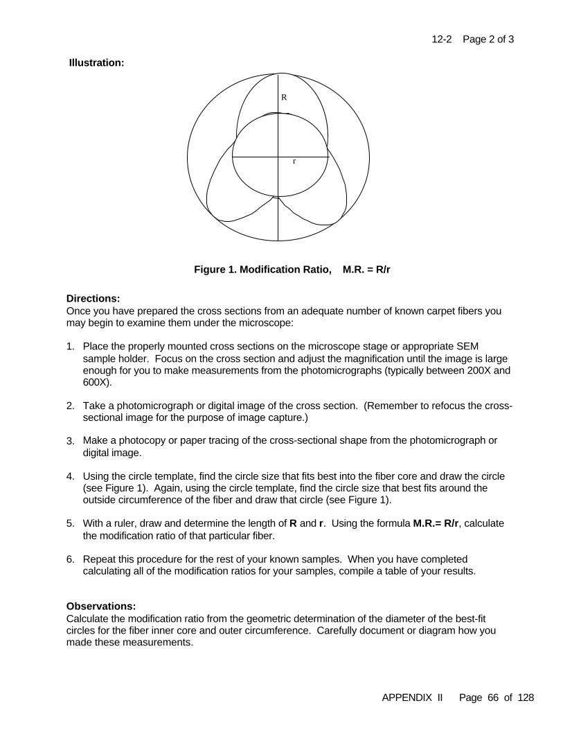
APPENDIX II Page 66 of 128
r
R
Figure 1. Modification Ratio, M.R. = R/r
12-2 Page 2 of 3
Illustration:
Directions: Once you have prepared the cross sections from an adequate number of known carpet fibers youmay begin to examine them under the microscope:
1. Place the properly mounted cross sections on the microscope stage or appropriate SEMsample holder. Focus on the cross section and adjust the magnification until the image is largeenough for you to make measurements from the photomicrographs (typically between 200X and600X).
2. Take a photomicrograph or digital image of the cross section. (Remember to refocus the cross-sectional image for the purpose of image capture.)
3. Make a photocopy or paper tracing of the cross-sectional shape from the photomicrograph ordigital image.
4. Using the circle template, find the circle size that fits best into the fiber core and draw the circle(see Figure 1). Again, using the circle template, find the circle size that best fits around theoutside circumference of the fiber and draw that circle (see Figure 1).
5. With a ruler, draw and determine the length of R and r. Using the formula M.R.= R/r, calculatethe modification ratio of that particular fiber.
6. Repeat this procedure for the rest of your known samples. When you have completedcalculating all of the modification ratios for your samples, compile a table of your results.
Observations:Calculate the modification ratio from the geometric determination of the diameter of the best-fitcircles for the fiber inner core and outer circumference. Carefully document or diagram how youmade these measurements.
APPENDIX II Page 67 of 128
12-2 Page 3 of 3
In some instances, you may have difficulty in selecting the “best fit” circle. What happens to thecalculated modification ratio if you use these alternate choices in finding the best fit? How do yourmodification ratio values compare to ones calculated from the same images by an experiencedexaminer?
Discussion:Engineering processes are used to develop cross sections for a specific end use. The first fiber tobe engineered was a trilobal fiber developed by DuPont in the 1960s. DuPont patented the trilobalcross-sectional shape based on the modification ratio. Since then, there have been many fiberspatented based on the cross-sectional shape. The characteristics of a fiber cross section coupledwith patented information may enable the identification of a specific manufacturer.
APPENDIX II Page 68 of 128
13-1 Page 1 of 3Chapter 13 Practical Exercise 13-1
Subject: Solubility Testing of Acetate and Triacetate Fibers
Time: 1 hour
Objective: To learn a microchemical technique for distinguishing acetate and triacetatefibers by solubility testing
Theory: Certain polymers can be distinguished from one another by their solubility behavior when mountedin specific organic liquids. Acetate (diacetate) and triacetate fibers exhibit similar optical propertiesand infrared spectra, making it potentially difficult to distinguish between these two generic fiberclasses using these techniques alone. The chemical differences between these two fibers are dueto the percent of acetylated hydroxyl groups on the cellulose backbone of these two polymers. Innormal cellulose acetate (diacetate) approximately 60% of the hydroxyl groups are acetylated whilein the triacetate more than 90% of these sites are acetylated. The percentage of hydroxyl groupsthat have been acetylated affects the solubility behavior of these polymers. Although solubilitytesting is destructive, when carried out according to the microchemical procedure described here,the loss of material is negligible in relation to the certainty of information gained.
References:David SK, Pailthorpe MT. Classification of textile fibres: production, structure, and properties. In:Robertson J, Grieve MC, editors. Forensic Examination of Fibres, 2nd edition. London: Francis &Taylor, 1999; 26-30.
Dupont Technical Information Bulletin X-156. Identification of Fibers in Textile Materials. TextileFibers Dept., Technical Service Section, E.I. DuPont de Nemours & Company, Inc., 1961.
Hartshorne AW, Wild FM, Bab NL. The discrimination of cellulose di- and tri-acetate fibers bysolvent tests and melting point determination. J For Sci Soc 1991; 31(4):457-461.
The Textile Institute. Identification of Textile Materials, 7th edition. Portsmouth NJ: Grosvenor Press,1975; 28-29, 181-187.
Longhetti A, Roche G. Microscopic identification of man-made fibers from the criminalistics point ofview. J Forensic Sci 1958; 3(2):303-329.
Stratmann M. Identification of textile fibers. In: Mitchell J, editor Applied Polymer Analysis andCharacterization. New York: McMillan Publishing Co., 1987; 387-411.
Tucker PA. Fibers, identification. In: Mark HF, editor. The Encyclopedia of Polymer Science andEngineering, 2nd edition, Vol. 8. New York: John Wiley and Sons, Inc., 1987.
Preparation: Prepare 5 ml of a 75% aqueous acetone solution (v/v).
APPENDIX II Page 69 of 128
13-1 Page 2 of 3
Materials:
• stereomicroscope, compound microscope with transmitted light• glass slides, cover slips • 75% aqueous acetone • chloroform • razor or scalpel blades, forceps• double-drawn pipettes or capillary tubes• authenticated and commercial samples of di- and triacetate fibers
Safety:Know the hazards associated with the solvents listed above and handle them according to the rulesprescribed in your laboratory. Use caution when using razor or scalpel blades and place usedblades in a sharps disposal container.
Directions: Perform steps 1-5 using authenticated di- and triacetate fibers. After you obtain accurate resultswith these known samples, practice using commercial acetate fibers provided by your trainer.
1. Place a microscope slide under a stereomicroscope (~40X to 80X magnification). Focus on theslide where you intend to position the fibers to be tested. Using the forceps, place a single fiberon the slide and cover with a cover slip.
2. Transfer the slide to the transmitted light microscope stage, being careful not to lose the fiberand cover slip. Focus on the fiber and check for Köhler illumination. With a capillary tube orpipette, place a drop of the acetone reagent next to the cover slip and allow it to flow beneath itby capillary action.
3. Observe the fiber as the reagent flows over the fiber and record your observations.
4. Repeat steps 1-3 on new preparations using chloroform as the reagent.
5. Practice and improve your technique by cutting small pieces from single fibers as follows:• Under the stereomicroscope, practice cutting off different size segments of a single fiber
on a microscope slide with a sharp blade, and performing steps 1-4 on the segments.• Document any differences in the behavior due to the size of the segment tested.• To prevent a fiber from blowing away while cutting, it may help to wet it down with a
temporary mountant. Once the fiber fragment is in place, allow the temporary mountantto evaporate, apply a cover slip fragment and perform the test.
Observations:Diacetate fibers dissolve in 75% acetone while the triacetate fibers do not. Triacetate fibers mayswell to as much as twice their diameter, but do not lose their crenulated appearance.
Triacetate fibers are immediately soluble in chloroform. Diacetate fibers will retain some crenulationfor at least 15 seconds in chloroform, eventually swelling 5 to10 times their normal diameter.
APPENDIX II Page 70 of 128
13-1 Page 3 of 3
Discussion:Di- and triacetate fibers are not easily differentiated by infrared microspectroscopy. In infraredspectral data bases for fibers, diacetate fibers show slightly more absorbance at 3489 cm-1 than triacetate fibers. Measurement of the actual refractive indices or melting behavior can also serve todistinguish these fibers. Acetates typically show low birefringence and a crenulated cross section,whereas the birefringence of triacetates is usually very close to zero. Heavily colored fibers maycause difficulties determining the refractive indices. Solubility testing may be the easiest method forrapidly making this determination.
Diacetate is the only manufactured fiber soluble in 75% acetone. Triacetate is the onlymanufactured fiber soluble in chloroform. Triacetate fibers are no longer manufactured in the UnitedStates, but are still imported to the United States.
Prior to running solvent tests on questioned/known casework samples, solvents should be tested onauthenticated fiber samples to insure reliability. Use only single fibers or small pieces of individualfibers. Fiber cross sections may also be used for this purpose. If several fibers are used, then theanalyst should be aware that overloading can affect the solvent composition and give anomalousresults. The analyst should disregard results obtained from fibers in contact with air bubbles at theedges of the cover slip.
APPENDIX II Page 71 of 128
14-1 Page 1 of 3Chapter 14 Practical Exercise 14-1
Subject: Use of a Hot Stage
Time: 6 hours
Objective: To learn how to use the hot stage for determining the melting point range ofmanufactured fibers, and identifying and differentiating fibers by means oftheir melting points
Theory: The determination of melting point ranges may be used to distinguish among certain fibers in thesame generic class, or may be used as part of an identification confirmation. Although a meltingpoint test is destructive, fiber samples previously prepared for non-destructive methods (e.g. microscopical examination of cross sections or fluorescence) can be used.
Manufactured fibers are a mixture of a base polymer, additives and sometimes finishes andcontaminants, rather than being composed of a single pure compound. These fibers are also amixture of crystalline and amorphous regions. The higher the degree of crystallization present, thehigher the melting point. Many fibers melt over a temperature range rather than at one specifictemperature point because of these factors. Polymer ratios, molecular weights, rate of temperaturerise and type of hot stage can also affect melting point.
References:Grieve MC. The use of melting point and refractive index determination to compare colourlesspolyester fibres. For Sci Int 1983; 22:31-48.
Hartshorne AW, Wild FM, Bab NL. The discrimination of cellulose di- and tri-acetate fibers bysolvent tests and melting point determination. J For Sci Soc 1991; 31(4):457-461.
Hartshorne AW, Laing DK. The identification of polyolefin fibres by infrared spectroscopy andmelting point determination. For Sci Int 1984; 26:45-52.
McCrone WC, Delly JG, editors. Hot and cold stage methods. The Particle Atlas, 2nd editon, Vol. 1Principles and Techniques. Ann Arbor, MI: Ann Arbor Science Publishers,1973; 114-116.
Preparation: Assemble materials and review your instrument’s operator manual. Prepare clean slides andmicro-cover slips for mounting materials. Fiber samples to be tested should be cut under thestereomicroscope. A very small length (~ 2 mm) is all that is needed because the melting point isobserved through a microscope.
Materials: • stereomicroscope and light source• compound microscope adapted with long working distance objective • hot stage and apparatus• razor or scalpel blades, • glass cutter or diamond-tip scribe
(list continues)

APPENDIX II Page 72 of 128
14-1 Page 2 of 3
• glass slides, glass cover slips, forceps, tissues• authenticated fiber samples• kit of calibration materials (see comments in Directions, Part 1)• acetone for slide cleaning• high-temperature stable silicone oil• reference literature containing melting point data
Safety:Be aware that the hot stage will reach high temperatures and the glass slide will be extremely hot. Use caution when using scalpel or razor blades and cutting slides or cover slips. Place used bladesin a sharps disposal container, and used glass slides and cover slips in a glass waste container. Follow standard laboratory safety procedures for working with chemical compounds.
Directions:
Part 1- Determining the Melting Range of a Manufactured Fiber
1. Dry mount a fiber of known melting point on a glass slide. 2. Insert slide in the hot stage and center fiber.3. The temperature of the hot stage unit can be raised quickly to approximately 15 OC lower than
the anticipated melting point, and then the rate of temperature rise lowered to about 2 OC/minute.If the test is a general melting point determination with no generic class identified and no meltingpoint anticipated, then a preliminary rapid increase of temperature can be used to find anapproximate melting point to use as an anticipated melting point.
4. The melting range is determined by observation of the fiber through the microscope from thetemperature at which melting begins to the temperature at which no more changes occur. Alsonote when approximately 50% of the fiber has melted, and note other thermal reactions such ascontraction of the fiber, charring, bubbling, and softening.
5. Repeat the test. Report the melting point as the average of the start and end points to thenearest degree Celsius. How reproducible were your values?
6. If available, repeat this test observing the fiber through slightly uncrossed polars and note thechanges in interference colors as the fiber melts. Does this type of viewing affect your ability toobserve melting behavior?
7. Repeat this test using fiber sections mounted in a minimal drop of high-temperature stablesilicon oil instead of dry mounts. Does this mountant make any difference in your ability toobserve melting or in your test results?
Part 2 - Identifying and Discriminating Nylon 6 and 6,6 by Melting Points
1. Mount a nylon 6 fiber and a nylon 6,6 fiber on one slide using silicone oil, cutting one “long” andone “short” so that you can visually discriminate them.
2. Insert slide in the hot stage and center fibers.3. Raise temperature quickly to approximately 195-200 OC.4. Lower the temperature rate to increase at about 2 OC/minute.5. Observe and record melting ranges and behaviors of the two fibers. Repeat the test. Report
the melting point as the average of the start and end points to the nearest degree Celsius. 6. Compare results to published melting point data.
APPENDIX II Page 73 of 128
14-1 Page 3 of 3
Part 3 - Comparing Fibers by Melting Points
1. Mount several short lengths of one fiber type on one slide.2. Heat, observe and record melting range and behavior as outlined above. Do all of the fiber
fragments on one slide react the same way at the same time?3. Repeat the test. Report the melting point as the average of the start and end points to the
nearest degree Celsius.4. Repeat test with at least ten different types of manufactured fibers such as acetate, modacrylic,
other nylons, olefins (polyethylene and polypropylene), polyesters (PET and PCDT), saran,spandex, and triacetate.
5. Compare results to published melting point data.
Observations:Observing through slightly uncrossed polars may aid in pinpointing the start and end of the meltingrange because the interference colors will decrease as the fiber melts. The fiber becomes isotropicunder crossed polars at the melting end point. High-temperature stable silicone oil added to thesample provides a more even heat distribution from the hot stage to the sample than a dry mountdoes.
It is always recommended to repeat the test and average the results. One operator’s duplicateobservations optimally should be within 2 OC, however, there is an inherent variability associatedwith this method.
Discussion:A melting point determination should generally be used when an identification cannot be achieved bynon-destructive methods. Although the melting point test has largely been replaced by moremodern instrumental methods, it can be a valuable tool in certain cases.
The melting points of the calibration materials will be much more discrete than for most of themanufactured fibers. Calibration should be performed at least annually or more often if criticalrefractive index work is being done. It can be seen from the published fiber melting point data tablesthat extreme accuracy with this method is not always necessary. For example, acetate andtriacetate, nylon 6 and nylon 6,6, polyethylene and polypropylene can be easily distinguished. Nylon 6 and nylon 6,6 have respective melting points of approximately 213 OC and 250 OC, adifference of 37 OC, which easily distinguishes the two fibers by this method.
Fibers from a common source should exhibit the same or very close melting points and behaviors. They should be tested under exactly the same conditions, preferably side by side on the same slide,and slight differences may be noted. A significant difference observed between two fibers wouldindicate two different sources. Fibers of the same generic class that appear microscopically similarmay exhibit differences in melting characteristics and these should be noted.
Fibers that do not melt under 300 OC include the following: acrylic, aramid, azlon, PTFEfluorocarbon, glass, acrylonitrile/vinyl chloride modacrylic, novoloid, rayon and natural fibers.
If using polarized light microscopy, then temperatures can be correlated to changes in fiberretardation and appearance. The isotropic point will be the point in which no retardation colors exist.
APPENDIX II Page 74 of 128
15-1 Page 1 of 4Chapter 15 Practical Exercise 15-1
Subject: Sample Preparation for FTIR - Microscopy
Time: 4 hours (Part 1 ~2 hrs, Part 2 ~2 hrs)
Objective: To illustrate the effect of fiber thickness on the quality of spectral data and toexplore the phenomenon of interference fringing
Theory:The shape and thickness of fiber samples can affect the data obtained from them. Up to a certainthickness, Beer´s Law is obeyed and there is a linear relationship between specimen thickness andpeak absorbance. Beyond a certain thickness this relationship breaks down. The ideal sample formaking transmission measurements using infrared microspectroscopy is one which is 5-15 µmthick. Some fibers may be much thicker than this such as nylon, polyester and polypropylene carpetfibers (e.g. 50-70 µm). The absorption bands (particularly the Amide I and II bands in polyamides)will be unresolved and will produce spectra where the relative peak absorbances are distorted insamples of such thickness. This can be overcome by flattening the fibers prior to running spectra. Flattening also reduces refraction effects and inaccuracies due to variable path lengths through thefiber.
If a fiber has a flattened surface (ribbon-like), then internal reflection of the beam may occur. In thissituation, some of the beam reaches the detector after having passed through the sample once, buta small fraction may be reflected twice thus reaching the detector after passing through the samplethree times. The detector receives the sum of two interferograms, one from the beam that passesthrough the sample once and one from the beam that has passed through it three times. Thecenters of the interferograms do not coincide because the doubly reflected beam has a longer pathlength. Therefore, the total interferogram has two centerbursts, a main one and a subsidiary. Theposition of the subsidiary centerburst depends upon the thickness and refractive index of thespecimen. Upon fourier transformation of the spectrum, the total interferogram produces thesample spectrum and the subsidiary is transformed into a broad band impurity in the spectrumwhich is manifested as a sinusoidally modified baseline. The interference fringes can be removedafter data acquisition, but this is a difficult process. The simplest remedy is to remove or reducethem by sample preparation involving roughening of the surface of the fiber.
References:Bartick EG. Considerations for fiber sampling with infrared spectroscopy, ASTM STP 949. In: RoushP, editor. The Design, Sample Handling and Application of Infrared Microscopes. Philadelphia PA: ASTM 1987; 64-73.
Tungol M, Bartick EG, Montaser A. Forensic examination of synthetic textile fibers by microscopicinfrared spectrometry. Humicki HJ, editor. Practical Guide to Infrared Microspectroscopy. New York:Marcel Dekker 1995; 245-285.
White GW. A simple high-pressure anvil and template device for the production of infrared spectrafrom microfiber samples. J Forensic Sci 1992; 37:620-631.
APPENDIX II Page 75 of 128
15-1 Page 2 of 4
Preparation:It is assumed the trainee has already been taught the standard operating techniques for producinginfrared spectra from fibers using the microscope-FTIR instrument available in their laboratory. Thedetector must be properly cooled, and the instrument purged of carbon dioxide and water vaporbefore use. Consult with your trainer to ensure that the instrument is properly prepared for use atleast 20 minutes before you will use it.
The trainer should provide authenticated samples of acrylic fibers and nylon 6,6 fibers. The polymercomposition of the acrylic fibers is not very important, but it will be helpful if the fibers are not toofine. A diameter of 20-25 µm should produce good results.
Materials:• microscope-FTIR instrument properly cooled and purged• stereomicroscope• fine scissors, fine forceps and scalpel blades• glass slides (smooth and rough)• double-sided adhesive tape• sample holder/discs (These may be the round metal disks with a central aperture as
normally supplied with the FTIR-microscope or double sided adhesive paper disks with apunch-out central aperture obtainable from specialty suppliers.)
• sample roller • microcompression cell accessory• authenticated fiber samples• dried potassium bromide
Safety: The microscope uses an MCT - detector which must be cooled with liquid nitrogen. Cryogenicgloves and eye protection should be worn when handling liquid nitrogen. Do not attempt to fill thedetector with liquid nitrogen for the first time without supervision. Use caution when using scalpelblades and place used blades in a sharps disposal container. Used glass slides should be put in aglass disposal container.
Directions:
Part 1 - The Effect of Fiber Thickness
Using the nylon 6,6 fiber sample and standard operating procedure, obtain spectra under thefollowing conditions :
1. Without any sample preparation: Position a single nylon 6,6 fiber across the aperture of asample disk. If necessary, secure the fiber ends with adhesive tape. Acquire the sample andbackground spectra.
2. Using some sample preparation: Take a single nylon 6,6 fiber and secure the ends with smallpieces of adhesive tape taut across the smooth area of glass slide. While viewing with thestereomicroscope, apply gentle pressure using the sample roller to flatten the fiber. Keep theroller flat to produce a uniform ribbon. Remove a portion of the flattened fiber and mount itacross the aperture of an appropriate sample disk, using double-sided adhesive tape ifnecessary. Acquire the sample and background spectra.
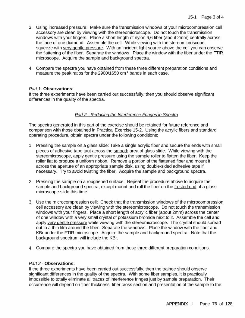
APPENDIX II Page 76 of 128
15-1 Page 3 of 4
3. Using increased pressure: Make sure the transmission windows of your microcompression cellaccessory are clean by viewing with the stereomicroscope. Do not touch the transmissionwindows with your fingers. Place a short length of nylon 6,6 fiber (about 2mm) centrally acrossthe face of one diamond. Assemble the cell. While viewing with the stereomicroscope,squeeze with very gentle pressure. With an incident light source above the cell you can observethe flattening of the fiber. Separate the windows. Place the window with the fiber under the FTIRmicroscope. Acquire the sample and background spectra.
4. Compare the spectra you have obtained from these three different preparation conditions andmeasure the peak ratios for the 2900/1650 cm-1 bands in each case.
Part 1- Observations:If the three experiments have been carried out successfully, then you should observe significantdifferences in the quality of the spectra.
Part 2 - Reducing the Interference Fringes in Spectra
The spectra generated in this part of the exercise should be retained for future reference andcomparison with those obtained in Practical Exercise 15-2. Using the acrylic fibers and standardoperating procedure, obtain spectra under the following conditions:
1. Pressing the sample on a glass slide: Take a single acrylic fiber and secure the ends with smallpieces of adhesive tape taut across the smooth area of glass slide. While viewing with thestereomicroscope, apply gentle pressure using the sample roller to flatten the fiber. Keep theroller flat to produce a uniform ribbon. Remove a portion of the flattened fiber and mount itacross the aperture of an appropriate sample disk, using double-sided adhesive tape ifnecessary. Try to avoid twisting the fiber. Acquire the sample and background spectra.
2. Pressing the sample on a roughened surface: Repeat the procedure above to acquire thesample and background spectra, except mount and roll the fiber on the frosted end of a glassmicroscope slide this time.
3. Use the microcompression cell: Check that the transmission windows of the microcompressioncell accessory are clean by viewing with the stereomicroscope. Do not touch the transmissionwindows with your fingers. Place a short length of acrylic fiber (about 2mm) across the centerof one window with a very small crystal of potassium bromide next to it. Assemble the cell and apply very gentle pressure while viewing with the stereomicroscope. The crystal should spreadout to a thin film around the fiber. Separate the windows. Place the window with the fiber andKBr under the FTIR microscope. Acquire the sample and background spectra. Note that thebackground spectrum will include the KBr.
4. Compare the spectra you have obtained from these three different preparation conditions.
Part 2 - Observations:If the three experiments have been carried out successfully, then the trainee should observesignificant differences in the quality of the spectra. With some fiber samples, it is practicallyimpossible to totally eliminate all traces of interference fringes just by sample preparation. Theiroccurrence will depend on fiber thickness, fiber cross section and presentation of the sample to the
APPENDIX II Page 77 of 128
15-1 Page 4 of 4
infrared beam. Variance will occur from sample to sample. Nevertheless, the spectra produced byroughening (2 and 3 above) should be of substantially better spectral quality than that produced byflattening on a smooth slide only.
Discussion:The trainee must decide what preparation is necessary to obtain satisfactory spectra and whethermore preparation is necessary to improve spectral quality. After the completion of theseexperiments and having read the appropriate literature, the trainee should be able to assess theamount of pressure required for flattening fibers to produce good quality spectra. The trainee shouldbe able to answer the following questions:
• Which of the three preparation methods has produced the best spectral resolution andpeak ratios?
• Why is it important to make sure that the pressure used in flattening fibers is keptrelatively constant when comparing samples?
• What are the advantages of flattening fiber samples?
• Name three possible disadvantages caused by applying too much pressure to themicrocompression cell.
• Why is it advantageous to place only one transmission window in the infrared beam?
Interference fringes can lead to a sinusoidal modification of the baseline, and, if not eliminated,could lead to erroneous conclusions during spectral comparisons. The effect can be reduced bysample preparation. Roughening of the surface of the flattened fiber can help to reduceinterference fringes by removing plane, parallel, and smooth surfaces. If the surface is too rough,then the incident beam will be attenuated by reflection and scattering. This may also occur due tothe presence of titanium dioxide delustrant particles in fibers. Scattering may result in a slopingbaseline, with the higher absorbance (lower transmittance) occurring at higher wavenumbers. Thetrainee must decide whether more preparation is necessary to improve the quality of the spectra.
APPENDIX II Page 78 of 128
15-2 Page 1 of 3Chapter 15 Practical Exercise 15-2
Subject: The Transmission/Reflection Technique
Time: 3 hours
Objective: To learn an alternative method for producing infrared spectra from fibers thatis particularly suitable for acrylic fibers, and to observe that FTIR-microscopycan be used to identify some manufactured fiber generic sub-classes
Theory:In the reflection-transmission technique (also known as reflection-absorption or double-pass transmission) the fiber is flattened onto a highly reflective metal substrate. The FTIR-microscope is operated in the reflection mode and the beam passes through the fiber, reflects off the metal surface and passes back through the sample a second time. The fiber should be flattened on a die (such as is used for pressing KBr) or a gold/silver mirrored disk or slide. Dedicated dies should be kept forthis purpose because the fibers will "imprint" onto the die surface. With double pass transmissionthe effective path length is nearly doubled so the technique is not suitable for fibers which are difficultto flatten, or those with a large diameter and high absorption (such as thick nylon carpet fiberswhich illustrate all of these characteristics). Acrylic fibers, which are normally thin and have lowabsorption, lend themselves well to this technique.
Acrylic based fibers can be sub-divided according to their polymer composition which may be recognized using infrared spectroscopy. Classification is based on the major co-monomer, the presence or absence of various solvent residues, and the presence or absence of additives used to provide dye sites or to perform special functions (e.g. flame retardancy).
References:Espinoza EO. Fiber analysis by reflective FTIR: a novel sample technique using copper and steelplates. Crime Scene 1998; 23(4) and 24(1):27.
Grieve MC. Another look at the classification of acrylic fibers using FTIR microscopy. Sci Justice1995; 35:179-190.
Grieve MC, Griffin RME. Is it a modacrylic?. Sci Justice 1999; 39:151-162.
Grieve MC, Griffin RME, Malone R. Characteristic dye absorption peaks found in the FTIR spectra ofcoloured acrylic fibres. Sci Justice 1998; 38(1):27-37.
Smalldon KW. The identification of acrylic fibres by polymer composition as determined by infraredspectroscopy and physical characteristics. J Forensic Sci 1973; 18:69-81.
Tungol MW, Bartick EG, Montaser A. Forensic analysis of acrylic copolymer fibres by infraredmicroscopy. Appl Spect 1993; 47:1655-1658.
Preparation:It is assumed the trainee has already been taught the standard operating techniques for producinginfrared spectra from fibers using the microscope-FTIR instrument available in their laboratory. Thedetector must be properly cooled, and the instrument purged of carbon dioxide and water

APPENDIX II Page 79 of 128
15-2 Page 2 of 3
vapor before use. Consult with your trainer to ensure that the instrument is properly prepared foruse at least 20 minutes before you will use it.
The trainer should provide authenticated, undyed acrylic/modacrylic fibers representing the mostcommon examples of these generic classes:
• acrylonitrile/vinyl acetate co-polymer, e.g. Acrilan (Monsanto)• acrylonitrile/methylmethacrylate co-polymer, e.g. Orlon (Du Pont), Cashmilon (Asahi), or Dralon (Bayer)• acrylonitrile/vinyl chloride, e.g. Kanekalon wig fiber (Kaneka Co.)
Other examples may be used or substituted provided that the samples are authenticated.
Materials:• microscope-FTIR instrument properly cooled and purged• fine scissors, fine forceps and scalpel blades• KBr die; gold or silver mirrored surface disks or slides • micro-press • authenticated fiber samples• ethanol for die/disk cleaning
Safety: The microscope uses an MCT- detector which must be cooled with liquid nitrogen. Cryogenicgloves and eye protection should be worn when handling liquid nitrogen. Use caution when usingscalpel blades and place used blades in a sharps disposal container.
Directions :
1. Place a length of fiber (3-5 mm) on a mirror disk (previously cleaned with ethanol) and coverwith another mirror disk.
2. Place the disks in a KBr press and apply pressure.
3. Take the disk with the flattened fiber on it and place in the die holder which fits on themicroscope stage. Adjust the measurement aperture to fit the fiber.
4. Use the microscope in the reflection mode. Focus on the mirror surface adjacent to the fiberand acquire a background spectrum.
5. Move the fiber into the aperture field. The fiber should be in focus without readjustment beingrequired. Acquire and store a spectrum from the fiber.
6. Repeat the above steps for the other two fiber samples. Always clean and re-use the samemirror disc.
Observations:Compare the spectral quality obtained in this exercise with the spectral quality obtained in PracticalExercise 15-1, Part 2 for rough pressed acrylic fibers recorded as air-mounts or using the microcompression cell. Decide which technique you think has given you the best result.
APPENDIX II Page 80 of 128
15-2 Page 3 of 3
Look at the spectra you have produced in this exercise and note the salient differences betweenthem. Can you attribute the differences to the varying polymer composition of the respective fibers?
Discussion:There is no one correct preparation method for producing spectra from single fibers. Analystsshould choose the method which they find works best for them and their particular instrument.Spectral quality will vary according to fiber thickness and cross-sectional shape. With somesamples it may be necessary to try different preparation methods until arriving at the one whichproduces the best quality spectra.
FTIR-microscopy can be used to identify fiber generic sub-classes. You should learn to recognizesome of the common examples among acrylic based fibers. If you have time to perform furtherexperiments, then your trainer may be able to provide you with additional varieties of acrylic ormodacrylic fibers which will illustrate different spectral features.
You may also try obtaining spectra from a deeply dyed acrylic fiber (black, dark blue, dark green)before and after extracting the dye (see Practical Exercise 19-2). Can you attribute any spectralpeaks to the dye which was present in the fiber?
APPENDIX II Page 81 of 128
15-3 Page 1 of 6Chapter 15 Practical Exercise 15-3
Subject: Interpretation of Fiber FTIR Spectra
Time: 4 hours
Objective: To become familiar with recognition and interpretation of infrared spectra fromthe most commonly encountered generic types of manufactured fibers
Theory:Fiber spectra may be identified in one of two ways. The first method is by comparison of spectraldata against a data base (computerized or hard copy). The position and intensities of the bands inthe spectrum are compared with the spectra of authenticated reference samples. The conditionsunder which the spectra have been recorded must also be taken into account. The generic classand the sub-generic class of synthetic fibers may be recognized. The second method is by usingskilled interpretation of the spectral features in which peaks can be assigned to functional groupsusing published peak tables or flow charts. Spectra are often characterized by dominant bands,such as the nitrile group at 2245cm-1 or the carbonyl C=O stretch found in fiber spectra between1750-1650cm-1.
Comparing to spectra in a data base may be done using software supplied with your instrument.The quality of spectral data will depend upon how they were collected. For this reason, the highestlevel of accuracy will be achieved using an operator-generated data base.
References:Bellamy L. Collection of tables of group frequencies. In: Infrared Spectra of Complex Molecules,Spectroscopy Library, Bowdoin College, Maine. London: Chapman and Hall, 1975.
Carton A, Carlsson DJ, Wiles DM . Infrared spectroscopy of polyethylene terephthalate fibres - usesand limitations. Textile Research Journal 1981; 52:28-34.
Grieve MC. New man made fibres under the microscope. Lyocell fibres and nylon 6 block co-polymers. Sci Justice 1996; 36(2):71 -80.
Grieve MC, Cabiness LR. The recognition and identification of modacrylic fibres. For Sci Int 1985;29129-146.
Grieve MC, Dunlop J, Kotowsk TM. Bicomponent acrylic fibres - their characterisation in theforensic science laboratory. J For Sci Soc 1988; 28:25-34.
Grieve MC, Kotowski TM. The identification of polyester fibres. J Forensic Sci 1977; 22:390-401.
Humecki H. Which nylon are these fibres? The Microscope 1994; 42(3):104.
Tungol MW, Bartick EG, Montaser A. The development of a spectral data base for theidentification of fibers by infrared microscopy. Appl Spect 1990; 44:1543-549.
Tungol MW, Bartick EG, Montaser A. Spectral data base of fibers by infrared microscopy.Spectrochim Acta 1991; 46B:535E.
APPENDIX II Page 82 of 128
15-3 Page 2 of 6
Was JD, Knittel D, Schollmeyer E. The use of FTIR microscopy for the identification of thermallychanged fibres. J Forensic Sci 1996; 41(6):1005 - 1011.
Young PH. The characterization of high performance fibers using infrared microscopy.Spectroscopy 1988; 3(9):24-30.
Preparation:The trainer will provide unlabeled copies of fiber spectra, including, but not limited to, the followinggeneric types :
• cellulose acetate• regenerated cellulose (rayon)• polyester• polyamide (nylon 6 and 6,6)• acrylic (vinyl acetate and methylacrylate co-polymers)• modacrylic• polypropylene• polyethylene• chlorofiber
Materials:• unidentified fiber spectra from the trainer• fiber identification flow charts A, B and C included in this exercise (provided and adapted
by MC Grieve from Robertton and Grieve, 1999)
Safety: There are no special safety requirements for this exercise.
Directions :1. Use the identification flow charts to identify the fiber types from each of the spectra as accurately
as possible by assigning functional groups to the most important peaks in each spectrum.
2. Determine which of the peaks and functional groups are crucial to the identification of each ofthe various fiber generic classes.
Observations:Discuss your identifications with the trainer. Once the results of your interpretive exercise havebeen confirmed as correct, the labeled spectra and charts may be retained for reference purposes.
Discussion:Successful identification is a matter of experience. One must be familiar with the basic spectralpatterns that you are likely to encounter, and must also be aware of all of the factors that maycause deterioration of spectral quality. Attempts to assign "trade names" to fibers should beavoided and discouraged. Fibers of the same polymer composition produced in different plants mayshow the same spectrum. Your identifications should be limited to generic class or sub-class.
Infrared spectra will not permit distinction between natural or man-made cellulosic fibers, orbetween natural protein fibers (with the exception of silk).
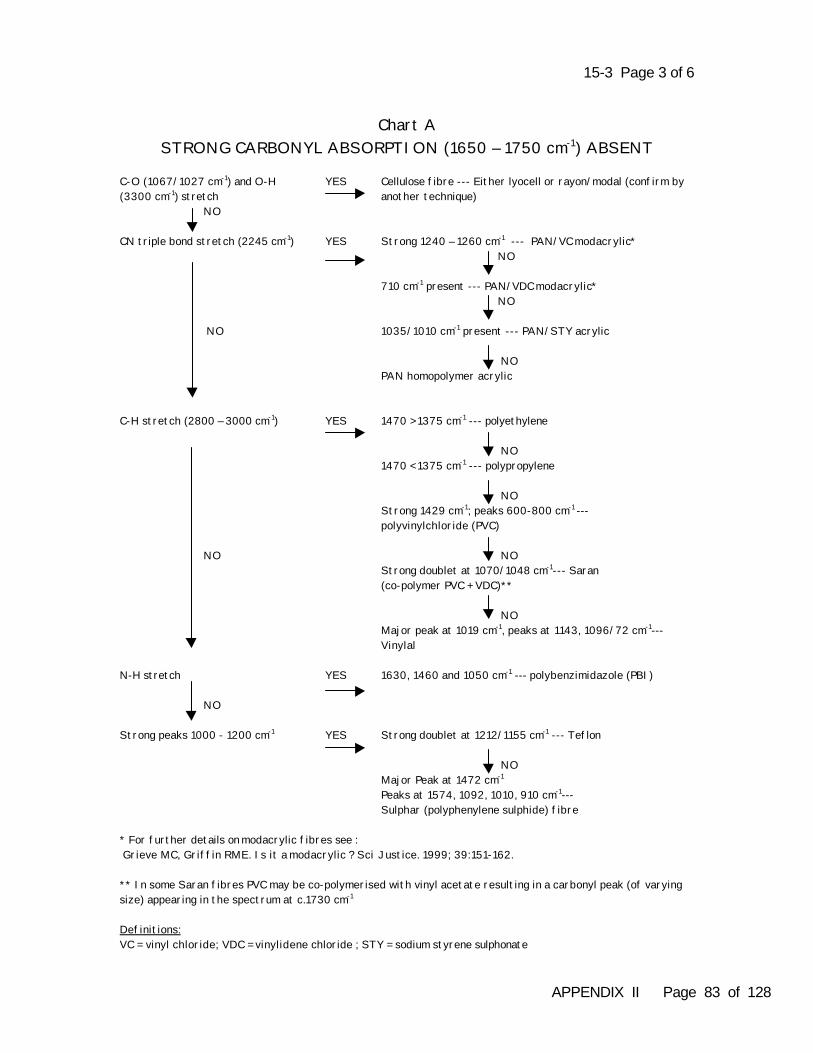
15-3 Page 3 of 6
Chart ASTRONG CARBONYL ABSORPTION (1650 – 1750 cm-1) ABSENT
C-O (1067/1027 cm-1) and O-H(3300 cm-1) stretch
YES Cellulose fibre --- Either lyocell or rayon/modal (confirm byanother technique)
NO
CN triple bond stretch (2245 cm-1) YES Strong 1240 – 1260 cm-1 --- PAN/VC modacrylic* NO
710 cm-1 present --- PAN/VDC modacrylic* NO
NO 1035/1010 cm-1 present --- PAN/STY acrylic
NOPAN homopolymer acrylic
C-H stretch (2800 – 3000 cm-1) YES 1470 > 1375 cm-1 --- polyethylene
NO1470 < 1375 cm-1 --- polypropylene
NOStrong 1429 cm-1; peaks 600-800 cm-1 ---polyvinylchloride (PVC)
NO NOStrong doublet at 1070/1048 cm-1--- Saran(co-polymer PVC + VDC)**
NOMajor peak at 1019 cm-1, peaks at 1143, 1096/72 cm-1---Vinylal
N-H stretch YES 1630, 1460 and 1050 cm-1 --- polybenzimidazole (PBI)
NO
Strong peaks 1000 - 1200 cm-1 YES Strong doublet at 1212/1155 cm-1 --- Teflon
NOMajor Peak at 1472 cm-1
Peaks at 1574, 1092, 1010, 910 cm-1---Sulphar (polyphenylene sulphide) fibre
* For further details on modacrylic fibres see : Grieve MC, Griffin RME. Is it a modacrylic ? Sci Justice. 1999; 39:151-162.
** In some Saran fibres PVC may be co-polymerised with vinyl acetate resulting in a carbonyl peak (of varyingsize) appearing in the spectrum at c.1730 cm-1
Definitions:VC = vinyl chloride; VDC = vinylidene chloride ; STY = sodium styrene sulphonate
APPENDIX II Page 83 of 128
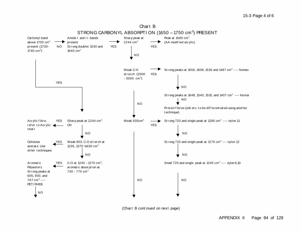
15-3 Page 4 of 6
Chart BSTRONG CARBONYL ABSORPTION (1650 – 1750 cm-1) PRESENT
Carbonyl bandabove 1700 cm-1
present (1730-1740 cm-1)
NO
Amide I and II bandspresentStrong doublet 1530 and1640 cm-1
YES
Sharp peak at2244 cm-1
NO
YES
Peak at 1680 cm-1
(AA modified acrylic)
YES
Weak C-Hstretch (2000- 3000 cm-1)
YESStrong peaks at 1656, 1608, 1536 and 1487 cm-1 ---- Nomex
NO
Strong peaks at 1648, 1540, 1515, and 1407 cm-1 ---- Kevlar NO
NOProtein fibres (silk etc. to be differentiated using anothertechnique)
Acrylic fibre,refer to Acrylicchart
YES Sharp peak at 2244 cm-1
CNWeak 935cm-1
YESStrong 720 and single peak at 1280 cm-1 ---- nylon 11
NO NO
Celluloseacetate. Useother techniques
YES Weak 903, C-O stretch at1235, 1370 >1430 cm-1
Strong 720 and single peak at 1270 cm-1 ---- nylon 12
NO NO
AromaticPolyestersStrong peaks at605, 930, and767 cm-1 ----PET/PHEB
YES C-O at 1240 – 1270 cm-1,aromatic absorption at730 - 770 cm-1
Small 720 and single peak at 1240 cm-1 ---- nylon 6,10
NO
NO
NO
(Chart B continued on next page)
APPENDIX II Page 84 of 128
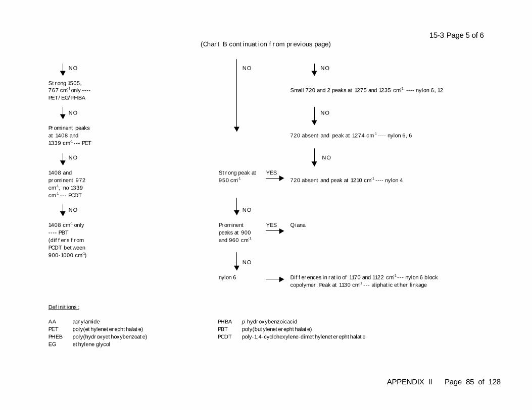
15-3 Page 5 of 6(Chart B continuation from previous page)
NO
Strong 1505,767 cm-1 only ----PET/EG/PHBA
NO
Small 720 and 2 peaks at 1275 and 1235 cm-1 ---- nylon 6, 12
NO NO
Prominent peaksat 1408 and1339 cm-1 --- PET
720 absent and peak at 1274 cm-1 ---- nylon 6, 6
NO
NO
NO
1408 andprominent 972cm-1, no 1339cm-1 --- PCDT
Strong peak at950 cm-1
YES720 absent and peak at 1210 cm-1 ---- nylon 4
NO NO
1408 cm-1 only---- PBT(differs fromPCDT between900-1000 cm-1)
Prominentpeaks at 900and 960 cm-1
YES Qiana
NO
nylon 6 Differences in ratio of 1170 and 1122 cm-1 --- nylon 6 blockcopolymer. Peak at 1130 cm-1 --- aliphatic ether linkage
Definitions :
AA acrylamide PHBA p-hydroxybenzoicacidPET poly(ethyleneterephthalate) PBT poly(butyleneterephthalate)PHEB poly(hydroxyethoxybenzoate) PCDT poly-1,4-cyclohexylene-dimethyleneterephthalateEG ethylene glycol
APPENDIX II Page 85 of 128
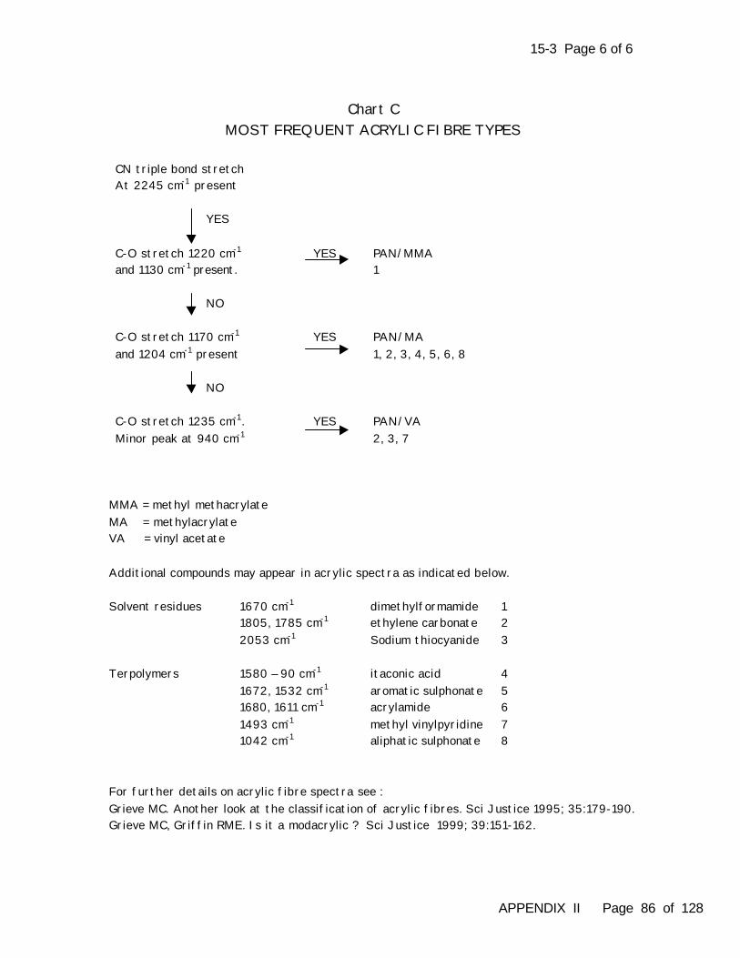
15-3 Page 6 of 6
Chart CMOST FREQUENT ACRYLIC FIBRE TYPES
CN triple bond stretchAt 2245 cm-1 present
YES
C-O stretch 1220 cm-1
and 1130 cm-1 present.YES PAN/MMA
1
NO
C-O stretch 1170 cm-1
and 1204 cm-1 presentYES PAN/MA
1, 2, 3, 4, 5, 6, 8
NO
C-O stretch 1235 cm-1 .Minor peak at 940 cm-1
YES PAN/VA2, 3, 7
MMA = methyl methacrylateMA = methylacrylateVA = vinyl acetate
Additional compounds may appear in acrylic spectra as indicated below.
Solvent residues 1670 cm-1 dimethylformamide 1 1805, 1785 cm-1 ethylene carbonate 2
2053 cm-1 Sodium thiocyanide 3
Terpolymers 1580 – 90 cm-1 itaconic acid 41672, 1532 cm-1 aromatic sulphonate 51680, 1611 cm-1 acrylamide 61493 cm-1 methyl vinylpyridine 71042 cm-1 aliphatic sulphonate 8
For further details on acrylic fibre spectra see :Grieve MC. Another look at the classification of acrylic fibres. Sci Justice 1995; 35:179-190.Grieve MC, Griffin RME. Is it a modacrylic ? Sci Justice 1999; 39:151-162.
APPENDIX II Page 86 of 128
APPENDIX II Page 87 of 128
16-1 Page 1 of 4Chapter 16 Practical Exercise 16-1
Subject: Using the Comparison Microscope with Brightfield Illumination
Time: 8 hours
Objective: To compare the color and morphological features of fibers using thecomparison microscope
Theory:A comparison microscope is used to perform side by side comparisons of questioned (recovered)fibers with those from a known (control) source. A comparison microscope consists of twocompound transmitted light microscopes connected with an optical bridge so that both fibers can beobserved simultaneously in the same field of view. In order to gain optimal resolution, specimencontrast and color balance, it is essential that the optical conditions on both sides of such aninstrument be properly balanced. Without the background illumination being properly balanced itwould be very risky and dangerous to come to any conclusions. Color perception by humans issubjective and depends upon ambient light, the object being viewed, and the observer. Perceivedcolor impressions can vary not only between individuals, but also by the same observer at differenttimes. For this reason it is necessary to employ additional objective methods of color examinationin forensic examinations.
References:Grieve MC. Fibres and their examination in forensic science. In: Maehly A, Williams RL, editors.Forensic Science Progress, Vol. 4. Berlin: Springer Verlag, 1990.
Robertson, J. Protocols for fibre examination and initial preparation. In: Robertson J, Grieve MC,editors. Forensic Examination of Fibres, 2nd edition. London: Francis & Taylor, 1999; 121-123.
Preparation: Comparison microscopes may vary from laboratory to laboratory. Before commencing theseexercises it is assumed that the trainee is familiar with the instrument in their laboratory and is ableto:
• set up and operate the microscope• color balance the light sources• correct any defects in the system
Notes to the trainer for slide preparations:
1. Color matching: The trainer should prepare a labelled set of ten (10) pairs of slides of differentfiber types (e.g. wool, cotton, polyester, nylon, acrylic, viscose rayon, etc.) including four (4) pairs ofnatural fibers and six (6) pairs of manufactured fibers. The sample pairs should be a mixture ofthose that match in color (from one source), and those which are of a very similar color but whichare dyed with a different dye or a different concentration of the same dye. Each pair should bemade from fibers of the same generic type, cross-sectional shape, delustrant status and denier formanufactured fibers. The best source of “matching” fiber samples is to select them from dyemanufacturers shade cards, where the dye has always been applied to the same fiber stock. (Thetrainer should check that this is the case.) The trainee should retain these slides for use in themicrospectrophotometry exercise in Chapter 18.
APPENDIX II Page 88 of 128
16-1 Page 2 of 4
2. Delustrant matching: The trainer should prepare six (6) fiber slides of authenticated, round,colorless, semi-dull polyester. All of the fibers on the slides should be the same diameter. Four (4)of the slides should be made from fiber samples which originate from different manufacturers (e.g.Du Pont, Hoechst) or are different types from the same manufacturer. Two (2) of the slides shouldbe made from fiber samples which originate from the same source.
3. Cross-sectional shape matching: The trainer should prepare a set of paired slides thatcontain fibers with matching or non-matching cross-sectional shapes and without having any otherobvious differences in color, diameter, delustrant, etc. Recommended subtle differences could beobtained from mixtures of round acrylic fibers together with those of bean and dog-bone crosssections, nylon carpet fibers which exhibit different modification ratios, and black pigmented fibersshowing different cross-sectional shapes, e.g. rayon and modal.
4. Morphological feature matching: The trainer should prepare two (2) slides each containing six(6) individually mounted “recovered” fibers, and provide a “known” fabric swatch made ofmanufactured fibers preferably showing a range of slight variations in morphological features ( e.g.in diameter). The mounted fibers should include some fibers that match fibers from the swatch andsome which are close, but do not match fibers from the swatch.
Permanent microscope slide preparations made during this exercise should be labeled carefully.
Materials:• comparison microscope• microscope slides and cover slips• fine forceps and fine scissors• suitable permanent mounting medium (e.g. Permount, XAM, etc.)• a set of 10 pairs of slides prepared by the trainer for color matching (The trainee should
retain these slides for use in the microspectrophotometry exercise in Chapter 18.)• a set of 6 slides prepared by the trainer for delustrant matching• a set of slides prepared by the trainer for cross-sectional shape matching• a set of slides and a fabric swatch prepared by the trainer for all morphological feature
matching in manufactured fiber materials• a set of 3 black cotton fabric swatches and a tuft of black cotton fibers prepared by the
trainer for all morphological feature matching in natural fiber materials
Safety:Know the hazards associated with the mounting media used and handle them according to the rulesprescribed in your laboratory.
Directions:
Part 1 - Making Slides to Assist in Balancing the Illumination
1. Choose a sample of a manufactured fiber which is uniformly dyed with a good depth of dyeingand preferably delustered (specific color is not important). An interesting cross section ormorphological feature is an advantage. Considering the purpose for which this fiber use is intended, it is better that the yarn contains a single fiber type only. Pigment dyed fibers (notblack) are quite good for this purpose.
APPENDIX II Page 89 of 128
16-1 Page 3 of 4
2. Take a length of yarn (about 1cm) from the sample and cut it in half. Tease some of the fibersfrom each half out in drops of mountant on two slides, so that you end up with two identicalpreparations from the same source. Do not overload the preparations with fibers.
3. Observe these two preparations on the comparison microscope after both sides of themicroscope have been set-up with Köhler illumination and the standard procedure for balancingthe light sources has been followed. The fibers should appear identical.
4. If the position of the slides is now reversed so that the slide on the left stage is now put on theright stage, then the fibers should still appear identical. If these conditions are satisfied, then thetrainee can be assured that the illumination is correctly balanced.
5. The trainee should retain these slides for personal use in evaluating the performance of thecomparison microscope before casework analysis.
Part 2 - Color and Morphological Feature Comparison
Your trainer should provide you with sets of slides or fabric (which are a mixture of matching andnon-matching pairs) for each of the examinations and comparisons specified below.
1. Examine all 10 pairs of slides made for the purpose of color comparison and decide which pairsare considered to be a match. For those which do not match, the trainee should discuss withthe trainer why they have reached this decision.
2. Examine the set of slides made for the purpose of delustrant comparison and compare all thesamples among themselves. Decide which, if any, match.
3. Examine the set of slides made for the purpose of cross-sectional shape comparison andcompare all the samples to each other. Decide which, if any, match.
4. Use the comparison microscope to examine the 12 fibers for the purpose of morphologicalfeature comparison and decide which, if any, could have originated from the "known" material.
5. Make the appropriate slide preparations from the black cotton swatches and fiber tuft. Use thecomparison microscope to examine and compare your preparations. Try to determine fromwhich of the black cotton fabric swatches the "recovered" fiber sample originated.
Observations:Observe, compare and document all of the fiber morphological features. Any of these features maybe of value in fiber comparisons. Did you observe any general or qualitative differences whencomparing manufactured fibers and natural fibers?
Discussion:In a casework situation, the comparison microscope must be used in a fiber association to ensurethat all morphological features are indistinguishable in both "recovered" and "known" samples.Careful and detailed observations must be made of all features. For example, subtle differences incross-sectional shape may be missed by inattention to detail.
APPENDIX II Page 90 of 128
16-1 Page 4 of 4
After carrying out these experiments the trainee should be aware that one can expect variation indye uptake and fiber diameter in natural fiber preparations (i.e. wool and cotton). They will have todecide whether they think that the features in the "recovered" sample fit within the range of thoseexhibited by the "known" sample.
Also, the trainee should have learned the very important role which delustrant plays in fibercomparisons. Not only the amount of the delustrant is important, but also the size and distribution ofthe particles.
If the microscope is fitted with a comparison fluorescence capability, then this exercise could berepeated using the different filter combinations available to determine if additional informationbecomes available which will help to confirm matches or exclude samples (see also Chapter 17 -Examining Fiber Samples Using Fluorescence Microscopy).
APPENDIX II Page 91 of 128
17-1 Page 1 of 3Chapter 17 Practical Exercise 17-1
Subject: The Fluorescence Microscope: Set-up and Operation
Time: 1 hour
Objective: To learn the techniques required to set up a fluorescence microscope for fiberexamination
Theory: Photoluminescence is described as the absorption and subsequent re-radiation of light from eitheran organic or inorganic material. Fluorescence is thus a form of photoluminescence in which lightemission continues only during the absorption of excitation light originating from an ultravioletsource. The time interval between absorption of excitation light and emission of re-radiated light influorescence is of short duration (1 x 10⁻⁹ sec). When electrons go from the excitation state to theground state, there is a loss of vibrational energy (Stokes Law/Stokes Shift).
Primary fluorescence, also called auto-fluorescence, originates from the object itself. Auto-fluorescence may mask materials having a more specific fluorescence in some applications. Various mounting media may exhibit auto-fluorescence (e.g. Permount). The use of these shouldbe avoided. Glass microscope slides and cover slips auto-fluoresce to some degree, but usuallywork satisfactorily during routine fiber examinations. Quartz slides may be purchased to eliminateany unwanted auto-fluorescence. Secondary, or induced fluorescence, involves non-fluorescentbiological materials impregnated with fluorochromes which fluoresce when excited by UV radiation.
In a fluorescence microscope, the specimen is illuminated with transmitted or reflected ultravioletlight from a high intensity light source such as a xenon or mercury arc lamp. Part of this light isabsorbed by the specimen and re-emitted as fluorescence. The wavelength of the re-emitted light islonger than that of the incident light. A primary (excitation) filter is placed between the lamp and thespecimen. This filter should provide light corresponding to the absorption maximum of the fiberbeing examined. To observe fluorescence, the light used for excitation is filtered out by a secondary(barrier) filter placed between the specimen and the eye.
The most convenient mode of examining fiber fluorescence is using reflected light. The excitationlight is directed down through the objective by means of a semi-transparent mirror (dichromaticmirror). The excitation and barrier filters, together with mirror are mounted in an interchangeableunit in more modern microscopes.
References:Bradbury S, Evennett PJ. Contrast Techniques in Light Microscopy. Microscopy Handbook 34.Oxford UK: Bios Scientific Publishers, Ltd, 1996; 91-100.
Have your fluorescence microscope owner’s manual available during this exercise for any specificset-up requirements.
Preparation: Prepare a standard slide(s) with fibers exhibiting a range of fluorescence from low tohigh in a mounting medium such as Norland 65 optical adhesive or XAM. These mounting mediaoffer low to almost non-existent auto-fluorescence.
APPENDIX II Page 92 of 128
17-1 Page 2 of 3
Materials:• microscope with reflected light fluorescence capability• authenticated fiber samples exhibiting fluorescence• standard slide with fibers exhibiting a range of fluorescence from low to high
Safety:Mercury and xenon arc lamps may explode during operation due to their high internal gas pressureand extreme heat generated during use. Never turn on a lamp outside its housing or observe thelamp directly when it is illuminated. If there is a problem with the lamp, DO NOT service it yourself;contact your trainer. Never look at ultraviolet excitation light directly. Ultraviolet light is inherentlydangerous and thus precautions must be taken in the proper set-up of the fluorescence microscopeto prevent inadvertent exposure of the retina to UV light. If supplied, then use the UV protectiveshade while positioning and viewing microscope slides. The shade will block UV radiation emittedfrom the mercury/xenon burner.
Directions:Using the known fiber slides perform the following steps to set-up for reflected light fluorescencemicroscopy:
1. Place a prepared slide containing a fiber on the microscope stage and focus on the preparation.
2. Set up the microscope for conventional transmitted light microscopy using the Köhlerillumination method.
3. Ignite xenon or mercury burner following your microscope instruction manual. To avoid straylight entering from underneath the preparation, remove the condenser and insert a light trap(available on some models) or an opaque material in its place.
4. Switch off transmitted light and dim the room lighting.
5. Depending on your specific model, either select a filter cube containing the dichroic mirror,excitation and barrier filters, or insert a dichroic mirror and a set of excitation and barrier filtersinto the light.
6. Refocus on the preparation, center and adjust the lamp and the reflected light field diaphragmuntil it is just outside the field of view.
7. Fully open the reflected light aperture diaphragm and remove all reflected light polarizers andanalyzers from the optical path.
Observations:Observe fluorescence intensity and color using a variety of known fiber standards and record yourobservations. If a red background is visible, then insert a BG38 (blue filter) or equivalent, which willsuppress the red color. If your microscope is so equipped, then change excitation and barrier filtersor filter cube to different wavelengths and record fiber fluorescence at various wavelengths.
APPENDIX II Page 93 of 128
17-1 Page 3 of 3
A uniform fluorescent test object, such as a white piece of paper which is often impregnated withfluorescent brightening agents, can be placed on the stage to test the function of the optical system. It is desirable to make the final microscope image as bright as possible. The brightness of the image can be maximized by ensuring optimal Köhler illumination (no frosted glass filters in theillumination system) and the use of lenses with the highest numerical aperture.
Discussion:With practice and critical observation you should be able to qualitatively estimate the subtlevariations in fluorescence observed between fiber samples. With practice you will be able toprepare cross sections of approximately five micrometers in thickness. The degree, intensity andpenetration of fluorescence can be characterized between examined cross sections.
The fluorescence properties between known and questioned samples can be characterized using acomparison light microscope equipped with an appropriate UV light source. Changes influorescence at a variety of excitation wavelengths can be evaluated while simultaneously viewingboth questioned and known fibers. As in conventional comparison light microscopy, the use ofmercury and xenon arc lamps should be assessed for proper Köhler illumination. Mercury burnersdo not provide an even intensity from ultra-violet to the infrared. It should be noted that both wattageand the size of the arc (the brightness per unit area within the back aperture of the objective)measure the useful brightness of the arc lamp. It is reported that xenon lamps have a more evenintensity across the visible spectrum than mercury lamps. Arc lamps displaying amperage, voltageand/or wattage should be individually monitored.
APPENDIX II Page 94 of 128
17-2 Page 1 of 2Chapter 17 Practical Exercise 17-2
Subject: The Effects of Mounting Media in Fluorescence Microscopy
Time : 2 hours
Objective: To examine and compare a variety of mounting media with respect to auto-fluorescence using a variety of excitation wavelengths
Theory: The choice of mounting media is critical when preparing samples for fluorescence microscopy. Mounting media exhibiting low auto-fluorescence are recommended, such as XAM or Norland 65optical adhesive. Occasionally, XAM, which is an aromatic solvent reduced mounting media, canhave adverse side effects on fibers and fluorescence brighteners, dissolving them and allowingthem to diffuse from the fiber. This normally happens very quickly after mounting. Use anothermounting medium if “bleeding” occurs upon sample mounting.
References:Cook R, Norton D. An evaluation of mounting media for use in forensic textile fibre examination. J Forensic Sci 1982; 22:57-63.
Kubic TA, King JE, DuBey IS. Forensic analysis of colourless textile fibres by fluorescencemicroscopy. The Microscope 1983; 31:213-222.
Preparation: glycerin/methanol solution (65:35)
Materials: • stereomicroscope and fluorescence microscope• microscope slides, cover slips, forceps • authenticated fiber samples exhibiting fluorescence• xylene, methanol, glycerin • the mounting media Permount, Meltmount nD1.525 (hot plate), Norland 65 (UV light source
to cure), and XAM
Safety:Mercury and xenon arc lamps may explode during operation due to their high internal gas pressureand extreme heat generated during use. Never turn on a lamp outside its housing or observe thelamp directly when it is illuminated. If there is a problem with the lamp, DO NOT service it yourself;contact your trainer. Never look at ultraviolet excitation light directly. Ultraviolet light is inherentlydangerous and thus precautions must be taken in the proper set-up of the fluorescence microscopeto prevent inadvertent exposure of the retina to UV light. If supplied, then use the UV protectiveshade while positioning and viewing microscope slides. The shade will block UV radiation emittedfrom the mercury/xenon burner.
Know the hazards associated with the solvents listed above and handle them according to the rulesprescribed in your laboratory. Use standard procedures employed in your laboratory while workingwith the hot plate.
APPENDIX II Page 95 of 128
17-2 Page 1 of 2
Directions:
1. Mount several representative fibers exhibiting fluorescence on individual microscope slides in• glycerin/methanol• xylene• methanol• Permount• Meltmount nD 1.525 • Norland 65 • XAM
2. Using a variety of excitation wavelengths, compare the background auto-fluorescence of eachmounting media and record your observations.
Observations:Observe the prepared slides using all excitation wavelengths (change filter cubes orexcitation/barrier filter sets) your microscope has available, and record any changes in auto-fluorescence. An undesirable high to very high auto-fluorescence will be observed using theglycerin/methanol solution, Permount and Meltmount nD 1.525 as the mounting media. Very low auto-fluorescence will be observed while using methanol, xylene, XAM and Norland 65 as the mountingmedia.
Discussion:Mount fibers using a mounting medium with the lowest possible auto-fluorescence. Permount,commonly used in fiber examination, is not recommended as a mountant for fluorescenceexamination due to its high auto-fluorescence characteristics. Norland 65 has a very low auto-fluorescence, but it is a permanent mounting media. The solvent of choice is methylene chloride ifyou need to remove a fiber from Norland 65.
APPENDIX II Page 96 of 128
17-3 Page 1 of 3Chapter 17 Practical Exercise 17-3
Subject: Observing Fluorescence on Fibers: Optical Brighteners, Dyes andContaminants
Time: 8 hours
Objective: To observe the fluorescence characteristics of optical brighteners, dyes andcontaminants of fibers
Theory:Optical brightening agents form a class of dyes which, when excited with UV light, fluoresce at theshort wavelength end of the visible spectrum emitting blue, sometimes violet or greenish-blue light. Brighteners introduced during manufacture are widely used industrially to give a ‘bright white’ look totextiles. Optical brightening agents present on fibers can also be derived from the consumer use ofdetergents, bleaches, fabric conditioners and soap. Wear and exposure may lead to furtherfluorescence modifications.
Manufactured fibers may be dyed in the spinning dope before the filament is formed, a processknown as solution dyeing or mass-colored dyeing. If dyes containing fluorescence properties areused, then the cross-sectional view will show homogeneous coloration and fluorescence. Fibersthat are dyed after being spun (surface dyeing) will show a range of dye penetration depths whichcan be observed by fluorescence microscopy.
Fibers may be contaminated with materials such as tape adhesive, oils, fats, pigments, toothpaste,denture cleaners, paints, lacquers, cosmetics, foodstuffs and soil which may fluoresce and interferewith the fiber’s fluorescence. These contaminants may be of evidentiary significance in specificcases, and therefore care must be exercised in determining if the contaminants should be removedprior to fluorescence examination.
References:Hartshorne AW, Laing DK. Microspectrofluorimetry of fluorescent dyes and brighteners on singletextile fibres: Part 1-Fluorescence emission spectra. For Sci Int 1991; 51:203-220.
Hartshorne AW, Laing DK. Microspectrofluorimetry of fluorescent dyes and brighteners on singletextile fibres: Part 2-Colour measurements. For Sci Int 1991; 51:221-237.
Hartshorne AW, Laing DK. Microspectrofluorimetry of fluorescent dyes and brighteners on singletextile fibres: Part 3- Fluorescence decay phenomena. For Sci Int 1991; 51:239-250.
Lloyd LBF. Forensic significance of fluorescence brighteners: their qualitative TLC characteristics insmall quantities of fibre and detergents. J For Sci Soc 1997; 17:145-152.
Palenik S. Microscopical examination of fibres. In: Robertson J, Grieve MC, editors. Forensic Examination of Fibres, 2nd edition. London: Francis & Taylor, 1999;173-175.
APPENDIX II Page 97 of 128
17-3 Page 2 of 3
Preparation:You will need to acquire a sufficient quantity of unbleached cotton fabric and a variety of laundrydetergents to complete Part 1. You will need to acquire a sufficient quantity of undyed cotton fabricand a variety of “contaminants” to complete Part 3.
Materials:• stereomicroscope and fluorescence microscope• microscope slides, cover slips, forceps• Norland 65 or XAM• small containers with lids (approximately 30 ml)• graduated cylinder • a selection of about eight to ten laundry detergents and fabric softeners such as Tide, All
and Bounce (liquid and powder)• unbleached cotton fabric• fiber samples containing optical brighteners• dyed fibers exhibiting fluorescence with a variety of dye penetration depths, and exhibiting
solution dyed and surface dyed processes• fiber cross-sectioning supplies
Safety:Mercury and xenon arc lamps may explode during operation due to their high internal gas pressureand extreme heat generated during use. Never turn on a lamp outside its housing or observe thelamp directly when it is illuminated. If there is a problem with the lamp, DO NOT service it yourself;contact your trainer. Never look at ultraviolet excitation light directly. Ultraviolet light is inherentlydangerous and thus precautions must be taken in the proper set-up of the fluorescence microscopeto prevent inadvertent exposure of the retina to UV light. If supplied, then use the UV protectiveshade while positioning and viewing microscope slides. The shade will block UV radiation emittedfrom the mercury/xenon burner.
Know the hazards associated with the solvents listed above and handle them according to the rulesprescribed in your laboratory. Use standard procedures prescribed by your laboratory while workingwith the hot plate. Use caution when using scalpel or razor blades and place used blades in asharps disposal container.
Directions:Part 1- Optical Brighteners
1. Characterize the unbleached cotton fabric using reflected light fluorescence microscopy at avariety of excitation wavelengths.
2. Cut small strips of cotton fabric and place each into labeled containers. Add approximately 20 ml of tap water to each container. Add several drops or granules of detergent to eachcontainer, close lid, agitate container for approximately 1 minute.
3. Wait one hour and remove each cotton strip.4. Cut each cotton strip in half. Rinse one of the two halves. Allow all to air dry.5. Tease one individual thread from each fabric sample and mount in Norland 65 or XAM. Label
each slide with the type of detergent used. 6. Examine each thread using a variety of excitation wavelengths. Compare each of the treated
threads to the unbleached cotton and to each other, noting intensity and/or color similarities anddifferences.
APPENDIX II Page 98 of 128
17-3 Page 3 of 3Part 2 - Dyed Fibers
1. Cross section dyed fibers (about 5 µm thick is acceptable) and mount in Norland 65 or XAM.2. Examine the cross sections using a variety of magnifications and excitation wavelengths.3. Record your observations and note the degree of dye penetration.
Part 3 - Contaminants
1. Characterize the undyed cotton fabric using reflected light fluorescence microscopy at a varietyof excitation wavelengths.
2. Apply a small amount of coffee with artificial creamer, watercolor paint, wallboard particles, oil,grease, lubricants, and soil on one side of separate pieces of the cotton fabric. Allow thematerials to dry, if possible.
3. Tease a thread from each fabric sample and mount on individual microscope slides in Norland65 or XAM. Label each slide with the name of the contaminating material used.
4. Examine each contaminated fabric using a variety of excitation wavelengths. Compare each ofthe contaminated threads to the uncontaminated cotton and to each other, noting intensity and/orcolor similarities and differences.
Observations:By comparing the fluorescence properties of a variety of detergents used in the optical brightenerexperiment, you should be able to observe subtle differences in intensity and possibly color. Manylaundry detergents have optical brighteners added to their formulations in amounts ranging fromapproximately 0.2 to 0.5 percent by weight. Optical brighteners are dyes (usually stilbenederivatives) that always have a blue-white fluorescence with ultraviolet excitation. One commonlyused optical brightener is Tinopal whitening agent manufactured by Ciba-Geigy.
Dyes and pigments may fluoresce in a variety of colors with different excitation wavelengths. Whendyes or pigments fluoresce, use all available excitation wavelengths with your microscope and notethe emission colors observed. Remember that the questioned fiber should exhibit the samefluorescence as the known fiber during comparisons. The characteristics of solution dyed versussurface dyed fibers will be observed in the cross-sectional orientation. Note the variation in dyepenetration of the surface dyed fibers.
Granular surface contaminants which may fluoresce, such as soil and wallboard, are easilydifferentiated from the underlying fabric and can be removed if necessary. Penetrating oils, grease,some foodstuffs such as non-dairy coffee creamer, and bodily fluids will mask the underlyingfluorescence properties of fibers and/or create additional anomalous fluorescence characteristicswhich can be observed on fibers in this experiment.
Discussion:Fluorescence microscopy can be used to determine if any fluorescing compounds were appliedduring the manufacturing, finishing or processing stages. Many spinning lubricants are oil basedand will fluoresce under UV excitation. It may also be possible to investigate the past chemicalhistory of a fiber. Examples of this may include the changes to fabric due to weathering fromexposure to sunlight and oxidation of synthetic polymer fibers such as polyvinyl chloride (PVC).
The trainee should be aware of the effect of fluorescence from a variety of bodily fluids commonlyencountered in casework. Fabric and fiber materials contaminated with urine, semen and/or bodydecompostion fluids may exhibit fluorescence.
APPENDIX II Page 99 of 128
18-1 Page 1 of 3Chapter 18 Practical Exercise 18-1
Subject: Microspectrophotometer Set-up and Operation
Time: 2 hours
Objective: To familiarize the trainee with the instrument’s operational limitations includingsystem stability, wavelength accuracy and resolution, photometric accuracy,linearity and absorbance limits
Theory: It is important, if not essential, to document instrument performance, accuracy and stability. For thisreason, most forensic laboratories have established quality assurance policies and procedureswhich specify instrument set-up and performance guidelines.
All instrumentation has practical and theoretical limitations. The instrument’s operator mustunderstand and document instrument performance, accuracy and stability before case samples areanalyzed.
References:Adolf FP. Remarks on the present state and the methodical limits of microscope photometry.Proceedings of the 10th International Association of Forensic Sciences Meeting, 1984; Oxford.
Eyring M. Spectromicrography and colorimetry: sample and instrumental effects. Analytica ChimicaActa 1994; 288:25-34.
Robson R. A closer look at microspectrophotometric data. Proceedings of the 3rd Meeting of theEuropean Fibres Group, 1995; Linkoping, Sweden:47-50.
Preparation: Review the operator’s manual for your instrument and your laboratory’s standard operatingprocedures for microspectrophotometry.
Materials: • UV/VIS microspectrophotometer (MSP) system (UV, if available) • NIST traceable reference absorbance standards (usually a set of 3 filters with a range
from 0.1 to 1.0 absorbance units)• NIST traceable wavelength calibration standards (e.g. Neodymium, Holmium, Didymium
or Erbium oxide glass filters)• an optical grade, spectral quality quartz reference filter (a clear reference filter usually
with the same refractive index as the absorbance filters)• any adjustment tools or peripheral instruments required for microspectrophotometer
set-up and calibration• the instrument’s historical calibration data
Safety:Review and adhere to the manufacturer’s safety recommendations for your instrument’s operation,adjustment and maintenance.
APPENDIX II Page 100 of 128
18-1 Page 2 of 3
Directions:
1. Turn on the instrument and light sources, allow them to thermally stabilize. Adjust microscope and spectrophotometer system for Köhler or partial Köhler illumination, and optimizespectrometer and detector optics. (Only partial Köhler illumination may be achievable because it is not possible to see the image of the filament on most modern microscopes.)
2. Set the instrument scan parameters: • step size for spectral scan instruments• number of scans for multi-channel instruments• desired wavelength range
Set instrument gain and/or measurement acquisition time as specified by the manufacturer. Ifavailable, system masking apertures will typically be left fully open for this test unless the MSPillumination is too intense for the detector. Always make sure to use the same objective forstandards measurement.
3. Place the clear reference filter in the light path. Focus on the filter (it will usually have a dot tofocus on) and acquire a “background spectra” on a clean area on the filter. This procedure willset the integration time for the instrument.
4. Perform a “dark scan” after closing off any light to the detector. The scan parameters should notbe altered. This will measure the amount of dark current in the instrument.
5. Restore the light path to the detector and take a reference scan of the reference filter. The scanparameters should not be altered. This measures and compensates for the light absorbingeffect of the clear reference filter, the light source, and the optics.
6. Run and record a standard wavelength calibration filter (or set of filters) spectra in both UV, ifpossible, and VIS range. Evaluate the wavelength accuracy of the instrument against thereported wavelength absorbance maxima supplied with the filter. Confirm that the MSPwavelength accuracy is within the required resolution window. This value is instrument andfilter-set dependant, typically ranging from 1 nm to 10 nm. Note any corrections or correctionfactors in the instrument’s calibration log. Evaluate the instrument’s wavelength accuracyagainst historical performance data.
7. Run and record a set of standard neutral density filter spectra in both UV, if possible, and VISrange. Evaluate the absorbance accuracy of the instrument against the reported absorbancevalues at the various wavelengths in the filter manufacturer’s certified calibration data. Note thatthe filter set should have been selected to test and validate both the detector linearity and cut-offwavelengths. Certified calibration values will be available for the near UV region for UV capableinstruments.
Observations:Assess and compare your MSP calibration results to the manufacturer’s provided expected resultsand the instrument’s historical record. Is the instrument set up and operating properly? What arethe performance limitations of the MSP with respect to absorbance non-linearity, spectral regions ofexcessive noise, and spectral bandwidth limitations?
Define and record the performance check and calibration results, and any correction factorsnecessary to meet the laboratory’s documentation requirements.
APPENDIX II Page 101 of 128
18-1 Page 3 of 3
Discussion:Absorption spectrophotometry is an inherently quantitative procedure that requires appropriatecalibration of wavelength and photometric response. Instrumental operating parameters for thecalibration should be the same as those used for normal casework. Periodically, the instrumentperformance should be comprehensively evaluated by using the same wavelength calibrationstandards with the instrument settings chosen to maximize system accuracy, precision andresolution. If the wavelength and/or absorbance values cannot be brought within the desired rangesby optimizing the microscope system, then the instrument’s manufacturer should be contacted.
APPENDIX II Page 102 of 128
18-2 Page 1 of 3Chapter 18 Practical Exercise 18-2
Subject: Acquiring Spectra From Single Fibers
Time: 5 hours
Objective: To evaluate dye variations, pleochroism and effects of various instrumentoperating parameters on single fiber examinations
Theory: Fibers rarely dye uniformly. A degree of non-uniformity exists within fibers that appear to beuniformly dyed. In addition, other factors such as fiber morphological variations (cross-sectionalshapes, inclusions, voids) and the optical phenomenon of pleochroism can affect the spectraobtained. Therefore, a range of absorbance spectra may be obtained if measurements are madealong the length of a single fiber.
References:Hartshorne AW, Laing DK. The definition of colour for single textile fibres by microspectro-photometry For Sci Int 1987; 34:107-129.
Houck M. Measuring dichroism in fibers by use of the microspectrophotometer. Proceedings of the5th Meeting of the European Fibres Group, 1997; Berlin:75-82.
Laing DK, et al. Colour measurements on single textile fibres. For Sci Int 1986; 30:65-77.
Robson R. Spectral variation within red cotton dyes. Proceedings of the 5th meeting of the EuropeanFibres Group, 1997; Berlin: 66-74.
Preparation: Perform instrument set-up, performance check and calibration as described in Practical Exercise18-1. This should be done as frequently as is specified by your laboratory’s operating procedures. Note that fibers used in this exercise will be needed for Practical Exercise 18-3.
Materials: • UV/VIS microspectrophotometer (MSP) system (UV, if available) • non-fluorescent mounting medium (spectral grade glycerin required if UV spectra are to be run) • slides and cover slips (made of quartz if UV spectra are to be run.)• forceps• round, semi-dull, uniformly colored, authenticated polyester, nylon and olefin fibers
(These fibers should originate from a colored thread or yarn which should be retained foruse in Practical Exercise 18-3.)
• single colored authenticated fibers including an acrylic, rayon and a natural fiber such ascotton, ramie, or silk (These fibers should originate from a colored thread or yarn whichshould be retained for use in Practical Exercise 18-3.)

APPENDIX II Page 103 of 128
18-2 Page 2 of 3
Safety:Know the hazards associated with the mounting media used and handle them according to the rulesprescribed in your laboratory.
Directions:
1. Mount the round, semi-dull polyester, nylon and olefin fibers per your laboratory’s operatingprocedure for UV/VIS MSP.
2. Place the mounted fiber preparation on the MSP stage with the fiber just outside of the opticalpath, adjust for Köhler or partial Köhler illumination.
3. Run and record background and fiber absorbance spectra using as many of the followingsystem configurations as are possible:
• no specimen mask(s) in the beam path• specimen mask(s) set just outside of the fiber edges• specimen mask(s) set just inside of the fiber edges• illumination field mask set just outside of the fiber edges and measuring aperture set
just inside of the edges
[Note: Older instruments have a variable specimen mask(s), after the specimen and notbetween the light source and the specimen, to reduce/eliminate stray light. Most moderminstruments do not have variable specimen masks and the field diaphragm is used toreduce/eliminate stray light]
4. Evaluate the resulting spectra and select the operational configuration that yields the spectrumwith the highest absorbance values, assuming that the fiber is not too dark for the dynamicrange of the MSP. This spectrum should be further evaluated for acceptable noise levels andany signs of exceeding the operational limits of the MSP. If the selected spectrum shows signsof exceeding the operational limits of the instrument, then make such corrective adjustments asare listed in the instrument manual. What are the possible remedies?
5. Note where the fiber’s absorbance maxima are in relation to the maximum system (lamp)energy shown in the background scan. What are the possible ramifications of absorbancemaxima that lay in the lower energy areas of the MSP’s background/blank spectrum?
6. Using the selected configuration and system parameters, run and record 5 absorbance spectrafrom a single location on the sample fiber in both the UV and VIS range. Make no adjustmentsto the MSP between runs. Compare the spectra for reproducibility.
7. Place a polarizing filter oriented E-W in the light path, somewhere between the light source andthe microscope stage. Using the selected configuration and system parameters, run andrecord 3 absorbance spectra from a single location on the sample fiber with a sample rotationbetween each measurement. (Rotate the MSP stage if equipped with a rotatable stage, orrotate your sample by hand on the MSP if equipped with a fixed stage.) Start with the fiberoriented E-W (horizontal), rotate 45 degrees in any direction for the second measurement, androtate it again so that the fiber orientation is N-S for the last measurement. Do not make any adjustments to the MSP between runs other than ensuring that the masks are appropriately setinside the fiber edges. Compare the spectra for reproducibility. Use both the UV and VIS rangeif available.
APPENDIX II Page 104 of 128
18-2 Page 3 of 3
8. Remove the polarizing filter. If your instrument has a specimen mask, then using the selectedconfiguration and system parameters, run and record 5 absorbance spectra at the samelocation on the fiber, resetting the mask(s) size, and refocusing the fiber and condenserbetween each run. Compare the spectra for reproducibility and note any apparent variations.
9. Using the selected configuration and system parameters, acquire, store and print absorbancespectra from 5 different regions of the sample fiber. Compare the spectra for dye uniformity.
10. Repeat this exercise using the mounted acrylic, rayon and natural fibers. In addition to theusual observations and comparisons among the spectra, take extra note of any absorbancespectra effects or variations related to fiber cross-sectional shape, inclusions or voids,diameter and surface variations.
Observations:Assess and compare spectra as requested in each part of the directions for wavelength andabsorbance differences.
Discussion:Changing instrumental parameters has a notable influence on absorbance spectra. The optimaloperational parameter set should be determined to yield the highest absorbance values. Thisparameter set should not change within a set of analyses. Reducing stray light in the MSP systemwill yield sample spectra with increased absorbance values and reproducibility.
By obtaining repeated absorbance spectra from a single location on the sample fiber it should beevident that the spectra are reproducible.
If a fiber exhibits pleochroism, then taking measurements as the fiber is rotated on the microscopestage will produce spectra that can have considerable wavelength and absorbance differences.When comparing fibers it is generally recommended that the same relative fiber orientation bemaintained for each sample.
By obtaining absorbance spectra from different regions along a single sample fiber without changingany operating parameters, it should be seen that the absorbance spectra do display variations whichcorrelates with the heterogeneity of the fiber dye even in an apparently uniformly dyed fiber. Thesemeasurements will vary depending on the fiber sample. Generally, spectra of fibers from naturalsources are more variable than from manufactured fibers. Other physical (e.g. cross-sectionalshape) and chemical variations within and between fibers can influence the spectra obtained. Measuring sites should be chosen to avoid obvious inhomogeneities within the area beingmeasured.
APPENDIX II Page 105 of 128
18-3 Page 1 of 4Chapter 18 Practical Exercise 18-3
Subject: Acquiring Known Spectral Sets and Comparing Spectral Curves
Time: 3 hours
Objective: To learn the typical dye uptake variation by fibers within a single yarn and tolearn spectrum comparison rules, guidelines and quality criteria
Theory: Fiber dyeing is generally non-uniform at the microscopic level. Dye concentration variations can,and usually do, exist along single fibers and among fibers dyed in a single thread or yarn. Dyevariations occur in fibers that appear to be “uniformly dyed” (such as round cross section nylons orpolyesters) and in fibers that appear unevenly dyed (such as cotton).
The meaningful comparison of UV/VIS spectra requires that they be evaluated from absorbanceplots to accurately compare the dye concentration differences that exist between different shadesof the same color. The color comparison of a questioned fiber to a known thread, yarn or fabricrequires a complete analysis of the full range of color variation shown by both items. For thisreason, it is important to compare the complete UV/VIS range of the questioned and known fibers.
References:Grieve MC, Biermann TW, Wiggins KG. Fibre comparisons using microspectrophotometry, letter tothe editor. Sci Justice 1999: 39(4):273.
Grieve MC, Dunlop J, Haddock P. An assessment of the value of blue, red, and black cottons astarget fibres in forensic science investigation. J Forensic Sci 1988; 33(6):1332-1344.
Grieve MC, Dunlop J, Haddock P. An investigation of known blue, red, and black dyes used in thecoloration of cotton fibres J Forensic Sci 1990; 35(2):301-315.
Hartshorne AW, Laing DK. Colour matching within a fibre data collection. J Forensic Sci 1988; 33(6):1345-1354.
Laing DK, et al. A fibre data collection for forensic scientists-collection and examination methods.J Forensic Sci 1987; 32:364-369.
Robson R, Wiggins KG. Fibre dye analysis-a comparative study of analytical pathways.Proceedings of the 4th Meeting of the European Fibres Group, 1996; London: 32-37.
Preparation: Perform instrument set-up and calibration as in Practical Exercise 18-1. This should be done asfrequently as is specified by your laboratory’s operating procedures. You should have retained asufficient amount of fiber yarn from Practical Exercise 18-2 to use in this exercise. If you did notretain such, then it is necessary for you to characterize new material before proceeding.

APPENDIX II Page 106 of 128
18-3 Page 2 of 4
Materials: • UV/VIS microspectrophotometer (MSP) system (UV, if available) • stereomicroscope (for fiber sampling and mounting)• forceps and teasing needles• non-fluorescent mounting medium
(spectral grade glycerin required if UV spectra are to be run) • slides and cover slips (made of quartz if UV spectra are to be run.)• a colored thread or yarn (same as used in Practical Exercise 18-2) used as the “known”• electronic and/or hard copy plots of the spectra produced in Practical Exercises 18-2 and
the same for any spectra produced in this exercise
Safety:Know the hazards associated with the mounting media used and handle them according to the rulesprescribed in your laboratory.
Directions: Part 1 - Acquiring Known Spectral Sets
1. Select individual fibers from the known thread or yarn to form a group of fibers that representsthe complete range of colors and color shades exhibited by the known. Anywhere from 5 to 10or more fibers may be necessary to represent all the variations in the known sample. Thesefibers should be selected and not randomly picked.
2. Mount the individual known fibers per your laboratory’s operating procedure for UV/VIS MSP.
3. Place the mounted fiber preparation on the MSP stage with the fibers just outside of the beampath and, if present, set the instrument mask(s)/aperture(s) to approximate the size and positionthey will be in for the fiber analysis. Run and record both background and 100% line spectraunder the conditions that will be used for the UV/VIS fiber analysis. Evaluate the 100% linespectrum for indications of absorbance from the mounting medium, slide and cover slip.
4. Obtain and record one absorbance spectrum for each of the selected known fibers in both theUV and VIS range. Use the same instrument setup and parameters that produced the optimumspectra in Practical Exercise 18-2.
5. Randomly pick a group of individual fibers from the known thread or yarn and repeat steps 2through 4.
Part 2 - Comparing Spectral Curves
1. The “known” fiber spectra obtained from Part 1 can be printed/plotted on a single graph.“Questioned” fiber spectra from Practical Exercise 18-2 should each be printed/plotted on aseparate sheet of paper for overlay comparison with the knowns. All spectra should have thesame units and ranges for the X and Y axes.
2. Examine the known and questioned fiber spectral data by overlaying them, and evaluate thefollowing spectral features:
• absorbance wavelength maxima and minima• peak slope angles
(evaluation points continue next page)

APPENDIX II Page 107 of 128
18-3 Page 3 of 4
• peak slope inflection points• overall peak shapes• absorbance range(s)• convoluted peaks• the relative peak heights within multiple peak spectra
3. Determine which of the spectra match. The questioned fiber spectra should fall within therange of the known set and should precisely overlay one or more of the known fiber spectra. Variations in dye concentration may preclude a precise overlay without spectral normalizationand other manipulation
4. If the questioned sample spectrum is outside the range of the known data set, then select-mount-run additional known fiber samples and/or analyze different areas of the previouslymounted known fibers to insure that the known material was comprehensively sampled. Re-evaluate the comparison in light of the additional spectra.
Observations:Spectra should be reviewed and evaluated for any focusing errors or other instrumental errors, andany unacceptable spectra should be rerun. Using the technique and criteria in Part 2 complete thefollowing evaluations:
• Compare spectra from the individually selected fibers in Part 1 to each other.
• Compare the spectral range of variations observed in the group of fibers selected torepresent the total range of the known in Part 1, to the range of variations observed inspectra collected from various locations along the length of a single fiber in PracticalExercise 18-2.
• Compare the spectral range of variations observed in the group of fibers selected torepresent the total range of the known in Part 1, to the spectral range of variationsobserved in the fibers randomly selected from the known in Part 1.
• Compare the spectra from the individual fibers obtained in Practical Exercise 18-2 (thequestioned fibers) to the known spectral set obtained in Part 1.
Review your evaluations of the spectral comparisons with your trainer. Discuss any spectralfeatures or comparison questions you may have. Can you correctly answer the following:
• What are the limits of variation between spectra described as “similar” that areacceptable in your laboratory? Why?
• What are the spectral differences that are considered “exclusionary” in spectralcomparisons made by your laboratory? Why?
• What is the acceptable terminology used to describe spectral comparisons? Note inparticular which terms are considered unacceptable or misleading, and understand whythat is so.
APPENDIX II Page 108 of 128
18-3 Page 4 of 4
Discussion:The need for multiple fiber sampling and multiple spectra collections during the evaluation of knownfiber or textile samples should have become evident. A range of absorbance spectra should havebeen obtained from the same thread or yarn. This spectral variation range typically is greater thanthe spectral variation range obtained from different locations along a single fiber.
Determining how many known fibers to select to be certain that you have a representative range isnot an easy task. Known fiber samples used to represent the color range should be criticallyselected to include the fibers from lightest to darkest and with visible differences in color. The full range of color variations present in a known sample may not be represented in a randomly selectedfiber sampling.
The trainee is encouraged to repeat this exercise with fiber types that typically have more inherentdye uptake variation such as cottons. It is the discriminating eye and the experience of the examinerthat ensures the detailed and adequate sampling of the knowns. As an approximation, usually 5 to10 known fibers will be sufficient, with 3 to 5 measurements along the length of each fiber.
If a representative range of the known sample has been established and the questioned fiberspectral features do not occur within this range of the known set, then the questioned fiber cannotbe associated with the known fibers/garment.
APPENDIX II Page 109 of 128
18-4 Page 1 of 2Chapter 18 Practical Exercise 18-4
Subject: Examining Metameric Fibers
Time: 4 hours
Objective: To learn what metameric fibers are and how to identify them
Theory: A metameric pair are two colors that appear the same in one set of lighting conditions but appeardifferent in another set of lighting conditions. Metameric textile fibers will therefore appear similarmacroscopically and microscopically but can be distinguished by UV/VIS spectroscopy and/or thinlayer chromatography.
References:Wiggins KG, Crabtree SR, Adolf FP, Grieve MC. The importance of analysis of reactive dyes oncotton fibres. Crime Lab Digest 1995; 22:89.
Macrae R, et al. The characterization of dyestuffs on wool fibres with special reference tomicrospectrophotometry. J Forensic Sci 1979; 24:117-129.
Preparation: Perform instrument set-up and calibration as performed in Practical Exercise 18-1. This should bedone as frequently as is specified by your laboratory’s operating procedures.
Materials: • UV/VIS microspectrophotometer (MSP) system (UV, if available) • stereomicroscope (for fiber sampling and mounting)• forceps and teasing needles• non-fluorescent mounting medium
(spectral grade glycerin required if UV spectra are to be run) • slides and cover slips (made of quartz if UV spectra are to be run.)• a pair of metameric fibers
Safety:Know the hazards associated with the mounting media used and handle them according to the rulesprescribed in your laboratory.
Directions:
1. Examine the fibers microscopically and compare their color. Mount the metameric fiber pair peryour laboratory’s operating procedure for UV/VIS MSP.
2. Place the mounted fiber preparation on the MSP stage with the fibers just outside of the beampath and, if present, set the instrument mask(s)/aperture(s) to approximate the size and position
APPENDIX II Page 110 of 128
18-4 Page 2 of 2
they will be in for the fiber analysis. Acquire and record both background and 100% line spectraunder the conditions that will be used for the UV/VIS fiber analysis. If your instrument is not UVcapable, then perform this step for the VIS range.
3. Acquire, store and print one absorbance spectrum for each of the fibers. Use the sameinstrumental set up and parameters that produced the optimum spectra in Practical Exercise18-2 using the full UV/VIS range if your instrument is UV capable. If your instrument is not UVcapable, then perform this step using the same instrumental setup and parameters thatproduced the optimum spectra in Practical Exercise 18-2 in the VIS range.
Observations:Compare spectra from the fibers by examining all of the parameters previously learned as points ofevaluation in Practical Exercise 18-3 Part 2. The metameric fibers should match in color bymicroscopical observation, but have different absorbance spectra in the UV and/or VIS ranges.
Discussion:Dyes that visually match in color can exhibit different UV and/or VIS spectra. Therefore, a visual ormicroscopical color comparison is not sufficient when comparing two fibers of visually similar colors. Microspectrophotometry is an essential technique to be used in fiber comparisons, and it isa technique that should be considered complimentary to other methods of color analysis.
APPENDIX II Page 111 of 128
19-1 Page 1 of 3Chapter 19 Practical Exercise 19-1
Subject: Classification of Fiber Dyes
Time: 2 hours
Objective: To learn a procedure to classify the dye type on polyacrylonitrile fibers
Theory: In 1970, Feeman compared classical methods of dye identification with the then more modernmethods. Dye identification schemes were based on determining the application class (direct,basic, etc.) and generic structure (anthraquinone, azo, etc.). Successful results depended on thedyes being homogeneous but even these were not identified chemically. Although he worked withlarge, non-forensic samples, his work has formed the basis of many of the systems now in use forfiber dye analysis in forensic science laboratories.
Generally, dye from single fibers can be sequentially extracted with a range of solvents. This allowsnot only for the most efficient dye extraction method, but also for the dye to be classified as long asa degree of caution is taken. Dyes used for coloring wool, polyamide, polyacrylonitrile, polyester,cellulosics, polypropylene and acetate fibers have been used in extraction and classification studies.
References:Beattie IB, Smalldon KW, Dudley RJ. The extraction and classification of dyes on single nylon,polyacrylonitrile and polyester fiber. J Soc Dyers and Colorists 1979; 95:295-301.
Feeman JF. An introduction to modern methods of dye identification-chromatography andspectrophotometry. Canadian Textile J 1970; 87:83-89.
Wiggins KG. Thin layer chromatographic analysis for fibre dyes. In: Robertson J, Grieve MC, editors.Forensic Examination of Fibres, 2nd edition. London: Francis & Taylor, 1999; 291-309.
Preparation: Prepare 10 ml of formic acid/water 1:1.
Materials: • scissors, forceps • glass tubes of appropriate diameter, glass pipettes or syringes, fine glass capillaries
• oven, hot plate and hot air stream (e.g. hair dryer)• TLC plates, 2 x 250 ml glass beakers, 2 petri dishes• glass scribe• methyl acetate, methanol, and formic acid/water 1:1• dyed acrylic fiber
Safety:Know the hazards associated with the solvents listed above and handle them according to the rulesprescribed in your laboratory. If these are not known to you, then consult the laboratory safety officer

APPENDIX II Page 112 of 128
19-1 Page 2 of 3
before proceeding with this experiment. Follow normal safety rules for handling and cutting glass inyour laboratory.
Directions: Perform the steps below using a known acrylic fiber which has been dyed. The fiber can beidentified as acrylic using infrared spectroscopy, if deemed necessary. A single fiber is all that isrequired to obtain a result as long as sufficient dye is present. The trainee may prefer to startexperimentation with a small tuft of fibers, and then repeat with single fibers when the technique hasbeen mastered.
1. Cut a long fiber into two pieces or divide a tuft in two.
2. Place each piece or tuft into a glass capillary tube that is heat sealed at one end, and is about2.5 cm in length, with an internal diameter of 1.5 mm. A fine wire is used to push the fiber downthe tube.
3. Label one tube “water blank” and add about 10 µl of distilled water (sufficient to cover the fiber)using a glass pipette or syringe.
4. Label a second tube “test material” (or similar identifier) and add about 10 µl of formicacid/water 1:1 (sufficient to cover the fiber) using a glass pipette or syringe.
5. Heat seal the tubes to prevent evaporation, and heat at 100 OC for 20 minutes.
6. The control and test samples are examined and compared visually to check for extraction of thedye. Pigmented or totally delustered acrylic fibers will not extract.
7. The tube containing the test material is cut open using a glass scribe. The extract is drawn upusing a finely drawn glass capillary.
8. A TLC plate is placed on a hot plate heated to approximately 70 OC.
9. The extract is applied 1 cm from the lower edge of the TLC plate to produce a spot ofapproximately 2 mm diameter. Once the spot is dry, the spotting process is repeated to ensurethe dye spot is strongly colored.
10. Dry the plate in an oven heated to approximately 100 OC for 5 minutes.
11. Place the plate in approximately 10 ml of methyl acetate in a 250 ml glass beaker which is thencovered with a glass petri dish.
12. The plate is eluted for about 2 mm above the origin, removed and dried in a hot air stream. Themethyl acetate is discarded.
13. If the dye has moved off the origin, then it is performing as a DISPERSE dye. If there is nomovement, then the plate should be placed in a clean beaker containing methanol and a freshattempt at elution made as in step 12.
14. If there is a sharp line at the solvent front, then it is performing as an ACID dye. If there is little orno movement, or if it is smeared, then it is performing as a BASIC dye. The methanol should bediscarded.
APPENDIX II Page 113 of 128
19-1 Page 3 of 3
Discussion:Having completed this exercise the trainee should be capable of classifying all dyes used to colorpolyacrylonitrile fibers. Classification procedures for other dyes and fiber types encountered inforensic textile fiber examinations can be found in the supplemental readings listed in Appendix I forChapter 18.
Dye classification may be useful for comparative purposes, and to assist in identifying a possiblemanufacturer.
APPENDIX II Page 114 of 128
19-2 Page 1 of 4
Chapter 19 Practical Exercise 19-2
Subject: Thin Layer Chromatography of Fiber Dyes
Time: 6 hours (Part 1 ~2 hrs, Part 2 ~2 hrs, Part 3 ~2 hrs)
Objective: To learn extraction and subsequent TLC procedures for bulk and single fibersamples using acrylic fibers as an example
Theory: TLC has been used to compare control and recovered fibers in criminal cases for over 25 years.Many of the dyes used to color textile fibers can be extracted using either pyridine/water 4:3 orformic acid/water 1:1. When dyes have been extracted from textile fibers they can be spotted onto a suitable TLC plate. Solvents (eluents) are then allowed to pass over the spot. Different components travel with thesolvents at different rates depending on their chemical and physical properties. Colors that arevisually similar can be made up of different component dyes. These can be easily and quicklydistinguished using TLC.
References:Beattie IB, Smalldon KW, Dudley RJ. Thin layer chromatography of dyes extracted from polyester,nylon and polyacrylonitrile fibres. For Sci Int 1981: 117:57-69.
Wiggins KG. Thin layer chromatographic analysis for fibre dyes. In: Robertson J, Grieve MC, editors.Forensic Examination of Fibres, 2nd edition. London: Francis & Taylor, 1999; 291-309.
Preparation: • Prepare 10ml of formic acid/water 1:1• Prepare Eluent A = chloroform, methyl ethyl ketone, acetic acid, formic acid 8:6:1:1• Prepare Eluent B = n-butanol, acetic acid, water 4:1:5
(Eluent B forms an upper and lower phase, only the upper phase is used as the eluent.)• Prepare standard dye solutions. Approximately 5 mg of each dye component are made
up to a final volume of 25 ml with pyridine/water 4:3 v/v. This can be used until the supplyis exhausted.
< The standard dye solution for Eluent A is: Solway green G (CI acid green 25),Superacet fast orange G (CI disperse orange 3), Superacet fast violet B (CIdisperse violet 8).
< The standard dye solution for Eluent B is: Solway green G (CI acid green 25),Solway blue RNS (CI acid blue 47), Naphthalene fast orange 2GS (CI acid
orange 10).
APPENDIX II Page 115 of 128
19-2 Page 2 of 4Materials:
• scissors, forceps, micropipette tubes, glass pipettes or syringes• oven, hot plate and hot air stream (e.g. hair dryer)• TLC plates, 4 x 250 ml glass beakers, 4 petri dishes, fine glass capillaries• glass scribe or equivalent• balance• methyl acetate, methanol, formic acid/water 1:1, chloroform, methyl ethyl ketone, acetic
acid, formic acid, n-butanol, water, pyridine/water 4:3, dyes as listed above• three sources of black 100% acrylic fibers
Safety:Know the hazards associated with the solvents listed above and handle them according to the rulesprescribed in your laboratory. If these are not known to you, then consult the laboratory safety officerbefore proceeding with this experiment. Follow normal safety rules for handling and cutting glass inyour laboratory.
Directions: Classify the dye on each of the acrylic fiber samples removed from the three acrylic sources as setout in Practical Exercise 19-1 Classification of Dyes. It is essential that all three sources used inthis practical exercise contain fibers with the same dye class. This should not be a problembecause the vast majority of acrylic fibers have dyes which classify as basic. If another dye class isidentified, then a different source should be used for these experiments. Proceed through thefollowing Parts 1, 2 and 3.
Part 1 - Testing of Eluents and Extractant
1. Use two TLC plates. Using a pencil, one is labeled in the top left-hand corner as Eluent A andthe other Eluent B. The two plates are placed on a hot plate (70 OC approximately).
2. One spot of the appropriate dye solution is applied 1 cm from the lower edge of the TLC plates,using a finely drawn capillary. The spot should be no larger than 2 mm diameter. Six to eightapplications of the formic acid/water 1:1 should be applied to form one spot alongside thestandard dye. This would represent a blank sample. Each application should be allowed to drybefore additional applications are applied.
3. Dry the plates in an oven at approximately 100 OC for 5 minutes.
4. Place each plate in approximately 10 ml of the appropriate eluent (the plate labeled A withstandard dye A should be eluted in eluent A) in a 250 ml glass beaker, which is then coveredwith a glass petri dish. The plates are eluted for about 2 cm above the origin, removed and driedin a hot air stream. The eluent is discarded.
Part 1 - Observations:If the standard dye has adequately separated, then the eluent is suitable for use. If the formicacid/water 1:1 solution is not showing any colored bands, then it is free from colored contaminantswhich may interfere with subsequent TLC.
If the standard dye does not separate adequately, then the eluent should be discarded and re-made,and the above procedure should be repeated. If colored bands appear on the formic acid/watertrack, then this should also be discarded and re-made, and the above procedure should berepeated.
APPENDIX II Page 116 of 128
19-2 Page 3 of 4
Part 2 - TLC of Basic Dyed Acrylic Fiber Bulk Samples
1. Place a small tuft of fibers removed from each of the three acrylic sources into labeledmicropipette tubes. Cover the sample with formic acid/water 1:1 and extract in an oven heatedto 100 OC.
2. A TLC plate is marked for the appropriate eluent and labeled at equidistant points across theplate indicating which sample should be applied in which position. The TLC plate is then placedon the hot plate.
3. The appropriate standard dye (for Eluent A) is applied to the plate 1 cm from the lower edge ofthe plate. In turn each of the three acrylic fiber dye solutions are applied to form a row of spotsacross the plate. The number of applications for each sample depends on the strength of thesolution. Sufficient applications are applied to produce a good colored spot.
4. Dry the plate in an oven heated to approximately 100 OC for 5 minutes.
5. Place the plate in approximately 10 ml of the appropriate eluent in a 250 ml glass beaker, whichis then covered with a glass petri dish. The plate is eluted for about 2 cm above the origin,removed and dried in a hot air stream.
6. Repeat this process for Eluent B.
Part 2 - Observations:The standard dye on each plate should have separated as previously observed when the dyes weretested. The test samples should have separated into their component colors. The degree ofseparation will depend on the dye(s) itself and the eluent system.
Each of the three samples has now been eluted in two different systems. Five parameters can nowbe considered to decide which is the best system for each of the samples:
• separation of component bands• sharpness of bands• movement from the origin• components traveling at or close to the solvent front• strength of dye extract from a single fiber that may need to be tested
Part 3 - TLC of Basic Dyed Acrylic Fibers of Differing Lengths
1. Select one of the three samples used in Part 2 and decide, by using the parameters listedabove, which eluent system is the most appropriate. Remove a single fiber from the sampleand cut it into lengths of approximately 1 mm, 2 mm, 4 mm, 6 mm and 8 mm.
2. Place each piece into a glass capillary tube about 2.5 cm in length, with an internal diameter of1.5 mm, heat sealed at one end. A fine wire is used to push the fiber down the tube. Each tubeshould be carefully labeled.
3. Add approximately 10 µl of formic acid/water 1:1 (sufficient to cover the fiber) to each tube usinga glass pipette or syringe. The tubes should then be heat sealed to avoid evaporation andincubated at 100 OC for 20 minutes.
APPENDIX II Page 117 of 128
19-2 Page 4 of 4
4. A TLC plate should be labeled in pencil with the details of the samples about to be applied. Thisis then placed on a hot plate at approximately 70 OC. The appropriate standard dye is spottedonto the plate.
5. The tubes containing the test samples are then cut open using a glass scribe. The entirecontents of each tube is then applied to form a spot on the TLC plate. In turn, a row of spots1 cm from the base of the plate is formed. Ensure that each application is dry before the next isapplied. The contents of each tube are then applied equidistant apart to correspond to thelabeling. It is preferable that the samples are applied in increasing order of length for ease ofcomparison.
6. Dry the plate in an oven heated to approximately 100 OC for 5 minutes.
7. Place the plate in approximately 10 ml of the appropriate eluent in a 250 ml glass beaker whichis then covered with a glass petri dish. The plate is eluted for 2 cm above the origin, removedand dried in a hot air stream. The eluent is discarded.
Part 3 - Observations:The standard dye should have separated as when previously tested. The test samples should haveseparated into their component colors. It will also be obvious that the separation and movement ofthe component colors is affected by the concentration of the dye. If a pale color sample was initiallyselected, then the shorter length samples may not show colored bands.
Discussion:Having completed the three parts of this exercise the trainee should be capable of extracting dyesfrom polyacrylonitrile fibers. They should also be able to obtain a thin layer chromatograph from bulkand single polyacrylonitrile fibers. Extracts from a bulk sample will contain a more concentrated dyesolution which may yield more color components. They should also be able to decide what is asuitable eluent system and why. Although this experiment is based on polyacrylonitrile fibers thetrainee should be able to adapt it to allow them to perform TLC on any fiber type containingextractable dyes.
APPENDIX II Page 118 of 128
21-1 Page 1 of 3Chapter 21 Practical Exercise 21-1
Subject: Examining Fabric Damage
Time: 6 hours
Objective: To understand the theory of how damage is created on fabric and recognizesome characteristic patterns of textile damage
Theory: Although it may not always be possible to identify the weapon causing damage to a fabric, oftenthere are recognizable and characteristic patterns of damage that could be associated to a type ofweapon or instrument utilized in creating the damage. There are many variables including, but notlimited to, the type of textile, fiber composition and construction of the fabric, type of instrument andmotion creating the damage, shape and sharpness of instrument edge(s), and underlying supportingstructure which can effect the fabric damage appearance.
The term STAB refers to damage caused by penetration of an instrument through the fabric. Theterm SLASH refers to damage caused by a sharp instrument along the fabric. The term TEARrefers to damage by physical stress exerted in opposing directions which creates a break throughthe fabric.
Despite the number of variables that may be involved in creating fabric damage, with someappropriate experience the characteristic patterns of damage should become recognizable and aidin the forming of an opinion as to the general type of weapon used or not used.
References:Adolf FP. Physical fits between textiles. Proceedings of the 3rd meeting of the European FibresGroup, 1995; Linkoping, Sweden.
Green MA. Stab wound dynamic-a recording technique for use in medico-legal investigations.J For Sci Soc 1978; 18:161-163.
Knight B. The dynamics of stab wounds. J Forensic Sci 1975; 6:249-255.
Monahan DL, Harding HWJ. Damage to clothing-cuts and tears. J Forensic Sci 1990; 35(4):901-912.
Stowell L, Card KA. Use of scanning electron mircroscopy (SEM) to identify cuts and tears in anylon fabric. J Forensic Sci 1990; 35 (4):947-950.
Taupin JM. Comparing the alleged weapon with damage to clothing-the value of multiple layers andfabrics. J Forensic Sci 1999; 44(1):205-207.
Preparation: There should be a specific time/day determined to perform this exercise in order to accommodatepurchase of the simulated skin without decomposition occurring, and to ensure other personnel’spresence for safety reasons.
APPENDIX II Page 119 of 128
21-1 Page 2 of 3Materials:
• stereomicroscope• various cutting and stabbing instruments including, at least, a single edge knife, double
edge knife, razor blade, scissors, a flathead screwdriver and Phillips screwdriver • various types of fabric including woven, knitted or nonwoven composed of different fiber
types and blends • uncooked rolled or flank of pork (described as a close representation of human skin)
Safety: This exercise requires the unusual and forceful use of sharp “weapons” on atypical substrates. Therefore, it is recommended that the weapon wielder take extra precaution in selecting personalprotective equipment which should include heavy duty eye protection and workman type gloves. The weapon wielding should be performed in the presence of other personal who must be outsidethe range of “weapon” action at all times but are available for immediate assistance should anyaccidental injuries or events occur.
Directions: Perform the following steps using the different cutting and stabbing instruments and fabricsconstructed with different materials. Repeat these steps with each different instrument.
1. Place the fabrics over the rolled or flank of pork. It is a good idea to cover the pork with paper toprotect the fabric from absorbing the pork oils.
2. Select one of the instruments to be used in creating fabric damage. Create damage to the fabricby stabbing, stabbing and tearing, or slashing the fabric in the area supported by the pork flank. Create “wounds” at varying angles to the weave or knit pattern. Also, create “wounds” in fabricthat is folded or wrinkled. Use a permanent marker to designate the type of instrument andmethod used. You should create a minimum of eight “wounds” per instrument and “wounding”method.
3. Repeat steps 1 and 2 for each instrument and each fabric sample.
4. Examine each of the damaged areas noting similarities or dissimilarities in the characteristicfabric damage as related to the type of instrument used and the fabric composition.
5. Cut each fabric sample in several directions and compare the appearance of the cuts to theother types of damage. Manually tear parts of the fabric and compare the appearance of thetears to the damage created by stabbing and slashing the fabrics. Attempt to physically matchthe torn free ends. Have someone else tear several types of fabric into pieces for you, and thenattempt to physically match the torn free ends.
6. Retain the damaged fabric sections for use in Practical Exercise 21-2.
Observations:The trainee should identify and describe in appropriate terms the characteristic similarities anddissimilarities among the types of instruments, acts of force, and fabrics used in this exercise. Thetrainee should start by noting the differences among sharp instruments (razor blade) and a dull knifeutilizing the stabbing, slashing and tearing methods.
APPENDIX II Page 120 of 128
21-1 Page 3 of 3
Discussion:Some of the described characteristic patterns of fabric damage that are typically reported in theliterature (see Monahan and Hearle) include:
• stab damage with a sharp instrument often displays a clean-even edge with a “nick” atone end;
• stab damage with a dull instrument often displays a disarray of fibers along the edge andevidence of stress to the yarns;
• slash damage often displays interrupted damage with yarns partially severed usuallyfound at the ends; and
• tear damage displays evidence of stress along the margin and ends.
Performing similar tests for an actual case may be necessary to substantiate one’s opinion as to thetype of instrument and act used to create the fabric damage. It should be emphasized that whenperforming these types of tests for an actual case the same type of fabric should be used in the testas is found in the actual case material. Different fabrics may display different characteristics usingthe same instrument.
APPENDIX II Page 121 of 128
21-2 Page 1 of 3Chapter 21 Practical Exercise 21-2
Subject: Environmental, Chemical and Mechanical Effects on Fabrics
Time: Variable
Objective: To explore and examine how different environmental, mechanical andchemical conditions affect fabrics
Theory:During the course of laboratory examinations or crime scene investigations you will encounterfabrics that have been subjected to environmental, mechanical and chemical damage. The textilematerial most commonly encountered will be clothing, however, one should not overlook other textilematerials.
Some conditions that may have led to observed fiber and fabric damage can be duplicated underlaboratory controlled experiments. Some types of observed fiber and fabric damage can berecognized by experience. The ability to recognize some types of damage, and to discriminate thedamage from normal wear patterns, can be very important in situations in which the conditions thatmay have led to the damage are difficult or impossible to duplicate in controlled experiments. Forexample, some fabric materials melt because of friction that may occur during the mechanics of ahit-and-run. These may be difficult, if not impossible, to duplicate but are important to recognize. This exercise will explore some of the conditions that may be duplicated under controlledcircumstances and allow noting the effects on fabrics.
References:Hearle JWS, Lomas B, Cooke WD. Atlas Of Fibre Fracture And Damage To Textiles, 2nd edition.Cambridge: Woodhead Publishing, 1998; 397-425.
Janaway RC. Degradation of clothing and other dress materials associated with buried bodies ofboth archaeological and forensic interest. In: Haglund WD, Sorg, MH, editors. Advances in ForensicTaphonomy: Method, Theory and Archaeological Perspectives. Boca Raton FL: CRC Press LLC,2001; 379-402.
Pelton W. Distinguishing the cause of textile fiber damage using the scanning electron microscope(SEM). J Forensic Sci 1995; 40:874-882.
Pelton W, Ukpabi P. Using the scanning electron microscope to identify the cause of fibre damage. Part II: an exploratory study. Can Soc For Sci J 1995; 28:189-200.
Ukpabi P, Pelton W. Using the scanning electron microscope to identify the cause of fibre damage. Part I: a review of related literature. Can Soc For Sci J 1995; 28:181-187.
Was J. Identification of thermally changed fibers. For Sci Int 1997; 85(1):51-63.
Preparation:In obtaining the clothing and other textiles for the exercise be sure that there is sufficient fabric of alike type to have comparison swatches and multiple swatches for various exposures. A secondhand clothing store may be a useful source of these materials.
APPENDIX II Page 122 of 128
21-2 Page 2 of 3
Materials: • stereomicroscope• sharp forceps, fine scissors and razor or scalpel blades • various types of clothing composed of different fiber types and weaves to include single
fiber compositions and blends • various other types of textile materials such as sheets, blankets, carpeting, towels• various chemicals and mechanical devices as suggested in the Directions section, and
your ingenuity and imagination
Safety:Familiarize yourself with the various properties and hazards associated with any of the chemicalsused. Use caution when using mechanical devices during the experimentation process and whenusing the razor or scalpel blades.
Directions:
1. Cut each of the fabrics into swatches such that a sample of the original material is retained as acomparison sample, and there is sufficient material to be used for experimentation.
2. Subject the fabric swatches to a variety of environmental, mechanical and chemical conditions.Record the type and duration of exposure. Some suggested types of exposures are:
• Environmental < weathering (sun, rain, snow, heat, cold)< burial< submersion in fresh, salt or pool water
• Mechanical< laundering< stretching/loading< crushing/impact< tying< abrading by rubbing, dragging, scuffing< burning< pinching, crimping< repeated use over a pulley system
• Chemical< acids like HCl, H2SO4, acetic< bases like NaOH, ammonia compounds (fertilizers)< ignitable liquids like gasoline, kerosene< bleach, hydrogen peroxide, other household chemicals
3. Perform some of the environmental testing, particularly burial or burning, on fabric samples from Practical Exercise 21-1. Examine severed edges from Practical Exercise 21-1 after the
fabric has been soaked with blood.
4. Compare the exposed fabric to the comparison sample. Note any changes, if any, that haveoccurred.
APPENDIX II Page 123 of 128
21-2 Page 3 of 3
Observations:Examine the test fabrics for damage and compare them to the saved comparison exemplars. Noteany changes from the original fabric samples, if any. Look for fading, degradation, and otherphysical changes. Look for differences in the reactions of the different fiber types in blends. Is onemore susceptible to exposure than the other? Accurate notes should be kept as to the type ofexposure or action, and the length of time or number of repetitions for the exposures.
Discussion:Your observations may show a wide range of variation. Some textile compositions may exhibitobvious changes while others exhibit no change. There may be some subtle differences that canonly be seen through very careful and thorough observation.
Blends may pose a situation in which one type of fiber may be more susceptible to damage than theother(s) such as bleaching or chemical degradation. It is important to recognize and note thecomposition of blended materials.
One should also observe the normal and typical wear and tear patterns exhibited on clothing. Lookat different wear patterns on your own clothing (e.g. pants, shirts, socks) to recognize some normalwear patterns. For example, it’s not unusual for blue jeans to exhibit fading at the knees and frayingaround the pocket areas.
The experimental exposures suggested in this exercise are not intended to be comprehensive. Youwill encounter circumstances related to casework that have not been included in this exercise. Youare encouraged to devise your own experiments that will simulate these newly encounteredscenarios and conditions, such as insect and animal damage.
APPENDIX II Page 124 of 128
22-1 Page 1 of 3Chapter 22 Practical Exercise 22-1
Subject: Composition and Physical Construction of Natural and ManufacturedFiber Cordage
Time: 6 hours
Objective: To learn techniques for assessing the composition and physical constructionof cordage
Theory: Numerous variations in construction, assembly, and fiber content can be found among existingcordage. The fiber content may be of natural or synthetic origin, and be homogeneous orheterogeneous. The fibers may be staple, filament or film. The cordage construction may vary fromsimple one-ply twisting of fibers to complex multi-component multi-ply twisted or braidedarrangements. All of these characteristics can serve as points of comparison between separatepieces of rope.
References:Laux DL. Identification of a rope by means of a physical match between the cut ends. J Forensic Sci 1984; 29(4):1246-1248.
Wiggins KG. Recognition, identification and comparison of rope and twine. Sci Justice 1995; 35:53-58.
Preparation: Note that Practical Exercise 22-2 will also require the use of the same cordage types examined inthis exercise. You will have to have sufficient material of the cordage type used in this exercise, orplan on doing more cordage characterizations in order to complete the next exercise.
Materials: • stereomicroscope• sharp forceps, fine scissors, razor or scalpel blades • a dark velvet-covered board (minimum 6 x 6cm)• various types of natural and synthetic fiber ropes, twines, and cords to include shoelaces
and drawstrings
Safety:Know the hazards associated with the use of sharp instruments and handle them according to therules prescribed by your laboratory.
Directions: Perform steps 1-9 for at least 6 different types of cordage. The variety of cordages shouldencompass natural and synthetic types, as well as various levels of structural complexities.

APPENDIX II Page 125 of 128
22-1 Page 2 of 3
1. Examine the cordage macroscopically and under the stereomicroscope. Determine the generalouter structural details to include, where applicable:
• diameter• length• type of structure (twisted and/or braided)• number of plies/strands• twist direction (Z or S)• type of braiding• length of lay (crowns or turns/cm)• color• internal and external marker yarns
2. Determine parts/components present (core and/or sheath(s)). This can be done by gentlyprying apart the outer plies to examine underneath. Also examine a cross-sectional view of a cutend of the cordage.
3. Separate the outer sheath plies at the end of the piece of cordage. Cut a one cm sample of oneof these plies. If other components exist (inner sheath, core), then sample these as well.
4. Where applicable, determine the following from the cut plies of each component:• twist direction of yarns or fibers (Z or S)• number of yarns twisted together• length of lay of twisted yarns• type of twisted fibers (staple, filament or film)• type of core (mono- or multi-filament)• color
5. For twisted yarns, determine the following:• twist direction of fibers (Z or S)• type of fibers (staple, filament)• presence of a core filament at center of twisted fibers
6. Determine the number of filament fibers per yarn or ply. This can be done by cutting a smallsection of the ply or yarn and spreading the fibers parallel to each other on a velvet-coveredboard. By displacing one fiber at a time with forceps, the fibers can be counted under astereomicroscope.
7. For a complete comparison of each component/part of the cordage the chemical compositionand color of the fibers must be analyzed with the appropriate microscopic, chemical orinstrumental technique(s), as applicable. This aspect has been dealt with in other sections ofthis training document.
8. For each type of cordage you are examining, cut one piece into two and attempt a physicalmatch. Disrupt the cut ends to some degree and again attempt a physical match.
9. For each type of cordage you are examining, attempt single and double edged force cuts, withand without tension stress. Attempt a physical match of the free ends, and examine the freeends macroscopically and microscopically to observe resultant separation characteristics.
APPENDIX II Page 126 of 128
22-1 Page 3 of 3
Observations:A checklist should be set up to document the relevant parameters observed by the trainee with eachcordage examination. Drawings may be useful in documenting the type of braiding present but thetrainee should still be learning to apply the appropriate terminology.
Discussion:In casework, the free ends of evidentiary cordage should be protected and not sampled to preservethe possibility of a physical match between a questioned and known item. In the absence of aphysical match, cordage is commonly examined in forensic casework for comparison purposes todetermine if two pieces could have originated from the same source. In this instance, allcomponents of the cordage should be examined and evaluated until a significant difference is found. Sometimes this requires full examination to determine if differences are “minor” or “significant”, andto possibly identify a manufacturer. The identification of a manufacturer may be useful forassessing production volume, availability and commonality of some cordage, and for otherinvestigative purposes.
It is important to note that one must be wary of the possibility of a heterogeneous fiber content incordage. This is particularly true for natural fiber cordage which may, in fact, vary along the lengthof the rope or twine.
APPENDIX II Page 127 of 128
22-2 Page 1 of 2Chapter 22 Practical Exercise 22-2
Subject: Environmental, Chemical and Mechanical Effects on Natural andManufactured Fiber Cordage
Time: Variable
Objective: To learn how different environmental, mechanical, and chemical conditions affect natural and synthetic fiber cordage
Theory: Cordage encountered during the course of an investigation or at a crime scene may have beensubjected to a number of different environmental, mechanical, and/or chemical conditionsdepending on the case circumstances. In some case situations the effects of these variousconditions on cordage fibers could appear to be significant and unexplainable discrepanciesbetween questioned and known samples, and, yet really be explainable discrepancies due todifferential exposures. In other case situations the various exposure effects on cordage fibers could be a significant point of positive comparison between questioned and known samples.
References:Kirk PL. Ropes, cordage and packaging material. In Thornton JL, editor. Crime Investigation, 2nd
edition. Malabar, FL: Krieger Publishing Co., 1974; 136-142.
Van Nostrand’s Scientific Encyclopedia, 6th editon, (see Rope). New York: Van Nostrand ReinholdCo., 1983.
Preparation: Refer to completed Practical Exercise 22-1. Make sure you have sufficient cordage from eachpreviously examined item to subject each to the following conditions. If this is not the case, then youshould examine and characterize additional cordage with sufficient material at hand to complete thisexercise.
Materials: • stereomicroscope• sharp forceps, fine scissors and razor or scalpel blades • a dark velvet-covered board (minimum 6 x 6 cm)• various types of natural and manufactured fiber ropes, twines, and cords to include
shoelaces and drawstrings • various chemicals and mechanical devices as suggested in the Directions section, and
your imagination
Safety:Familiarize yourself with the various properties and hazards associated with any of the chemicalsused. Be cautious when using mechanical devices during the experimentation and when using therazor or scalpel blades.
APPENDIX II Page 128 of 128
22-2 Page 2 of 2Directions: 1. Subject the cordage previously examined in Practical Exercise 22-1 to a variety of
environmental, mechanical, and chemical conditions. Record the type and duration of exposure. Some suggested types of exposures are:
• Environmental < weathering (sun, rain, snow, heat, cold)< burial< submersion in fresh, salt or pool water
• Mechanical< laundering< stretching/loading< crushing/impact< tying< abrading by rubbing, dragging, scuffing< burning< pinching, crimping< repeated use over a pulley system
• Chemical< acids like HCl, H2SO4, acetic< bases like NaOH, ammonia compounds (fertilizers)< ignitable liquids like gasoline, kerosene< bleach, hydrogen peroxide, other household chemicals
2. Re-examine the cordage using the same techniques learned from Practical Exercise 22-1. Noteany changes from the original conditions you observed, if any. Examine all fiber types and layersof construction from outside to inside for signs of damage or change. Accurate notes should bekept as to the type of exposure or action, and the duration and number of repetitions.
Observations:Careful examination and documentation of the rope fibers from the outside to the inside is important. Can you make any generalizations about any of the exposure conditions relative to the fiber orcordage types you examined?
Discussion:Your observations probably show a wide range of variation among the different cordage types, andamong the different conditions to which they were exposed. Some ropes may be very vulnerable toone set of conditions while another may be inert or unaffected. Careful examination of the ropefibers from the outside to the inside is important to determine the depth and extent of damage, if any. For example, the outer exposed fibers may show sun bleaching and disintegration while internalfibers may be protected and retain their original coloration and viability. A rope composed ofdifferent materials may not show any significant changes externally because the outer material isinert to chemical exposure while the internal fibers, with a different composition, may be moresusceptible to the chemical exposure.
The experimental exposures suggested in this exercise are not intended to be comprehensive. Youwill encounter circumstances related to casework that have not been included in this exercise. Youare encouraged to devise your own experiments that will simulate these newly encounteredscenarios and conditions, such as insect and animal damage.