A Flat Track JK Spec Chassis - IRRA Slot Racing
14
A Flat Track JK Spec Chassis By Mike Swiss Shortly after Joe "Noose" Neumeister launched the IRRA website, a discussion started on doing some "How-to" articles. The thought was we needed one that would help the new racer or someone with very little chassis building experience. It made sense we use a JK chassis kit since the IRRA had just started a JK Spec Class geared for non-experts. With having a request from a customer, Jimmi Bostrom, for a JK RTR chassis, it made sense I take some pictures while building it. The torsion-style pan flex he wanted would be a bit easier to build vs. a hinged model. Also, I kept the bends as simple as possible on the six pieces of wire I used. It was also suggested; if possible, build it without using a jig to help someone who hadn't purchased one yet. I went ahead and did that. While I used my circa 1984, slate wing car chassis jig, I didn't use the guide post or any of the scribed markings. I only used it because it's on legs which facilitated clamping. The finished article is admittedly "Minutia Mania". I did it with the only assumption being, the reader would know what end of the soldering iron to hold. I wanted it to have a similar feel as the benchmark series of building articles Lee Gilbert did for Car Model in 1973. I stopped short of asking my fiancé to clean the chassis while taking a bubble bath, like Lee was able to convince Donna to do. But hopefully I injected enough levity for the reader to utter at least once, the most heard phrase at Chicagoland Raceway's Saturday night races: "Swiss, there must be something seriously wrong with you."* *© 2005 - "Sano" Dave Fiedler We'll start with adding a guide tongue brace. Even though I sell them, I don't think they're that necessary. But since the chassis is for a customer who likes all the bells and whistles, I'll throw one on. Since I said I wasn't going to use a jig, I'll just use a 10-32 machine screw with a Sonic brass nut to keep it aligned. The IRRA Gang of Seven (Go7) are back-seat builders. They're reminding me to make sure I clamp the chassis with the area to be soldered, hanging off the end, so the block doesn't act quite as much like a heat sink. While you want to make sure you get the chassis parts hot enough for the solder to flow, there's no reason to overheat them. While more so with aluminum, which won't be used, in extreme cases, you can start softening metal up.
Transcript of A Flat Track JK Spec Chassis - IRRA Slot Racing
A Flat Track JK Spec Chassis By
Mike Swiss Shortly after Joe "Noose" Neumeister launched the IRRA website, a discussion started on doing some "How-to" articles. The thought was we needed one that would help the new racer or someone with very little chassis building experience. It made sense we use a JK chassis kit since the IRRA had just started a JK Spec Class geared for non-experts. With having a request from a customer, Jimmi Bostrom, for a JK RTR chassis, it made sense I take some pictures while building it. The torsion-style pan flex he wanted would be a bit easier to build vs. a hinged model. Also, I kept the bends as simple as possible on the six pieces of wire I used. It was also suggested; if possible, build it without using a jig to help someone who hadn't purchased one yet. I went ahead and did that. While I used my circa 1984, slate wing car chassis jig, I didn't use the guide post or any of the scribed markings. I only used it because it's on legs which facilitated clamping. The finished article is admittedly "Minutia Mania". I did it with the only assumption being, the reader would know what end of the soldering iron to hold. I wanted it to have a similar feel as the benchmark series of building articles Lee Gilbert did for Car Model in 1973.
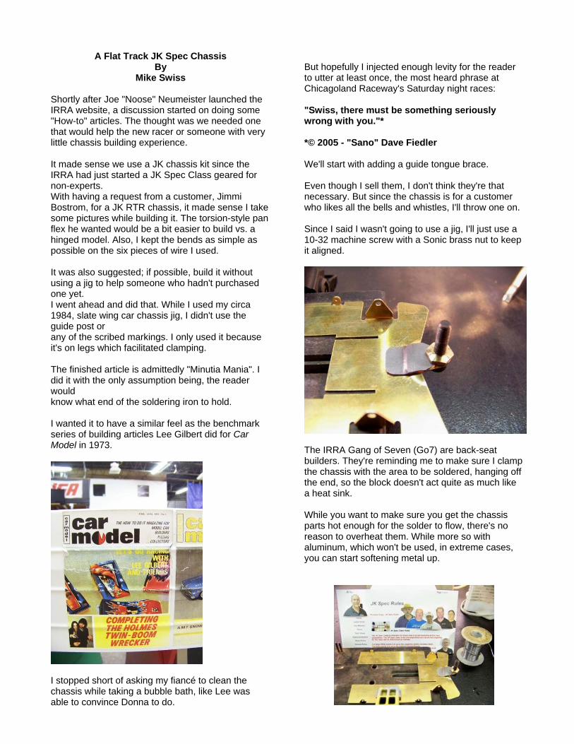
I stopped short of asking my fiancé to clean the chassis while taking a bubble bath, like Lee was able to convince Donna to do.
But hopefully I injected enough levity for the reader to utter at least once, the most heard phrase at Chicagoland Raceway's Saturday night races: "Swiss, there must be something seriously wrong with you."* *© 2005 - "Sano" Dave Fiedler We'll start with adding a guide tongue brace. Even though I sell them, I don't think they're that necessary. But since the chassis is for a customer who likes all the bells and whistles, I'll throw one on. Since I said I wasn't going to use a jig, I'll just use a 10-32 machine screw with a Sonic brass nut to keep it aligned.
The IRRA Gang of Seven (Go7) are back-seat builders. They're reminding me to make sure I clamp the chassis with the area to be soldered, hanging off the end, so the block doesn't act quite as much like a heat sink. While you want to make sure you get the chassis parts hot enough for the solder to flow, there's no reason to overheat them. While more so with aluminum, which won't be used, in extreme cases, you can start softening metal up.
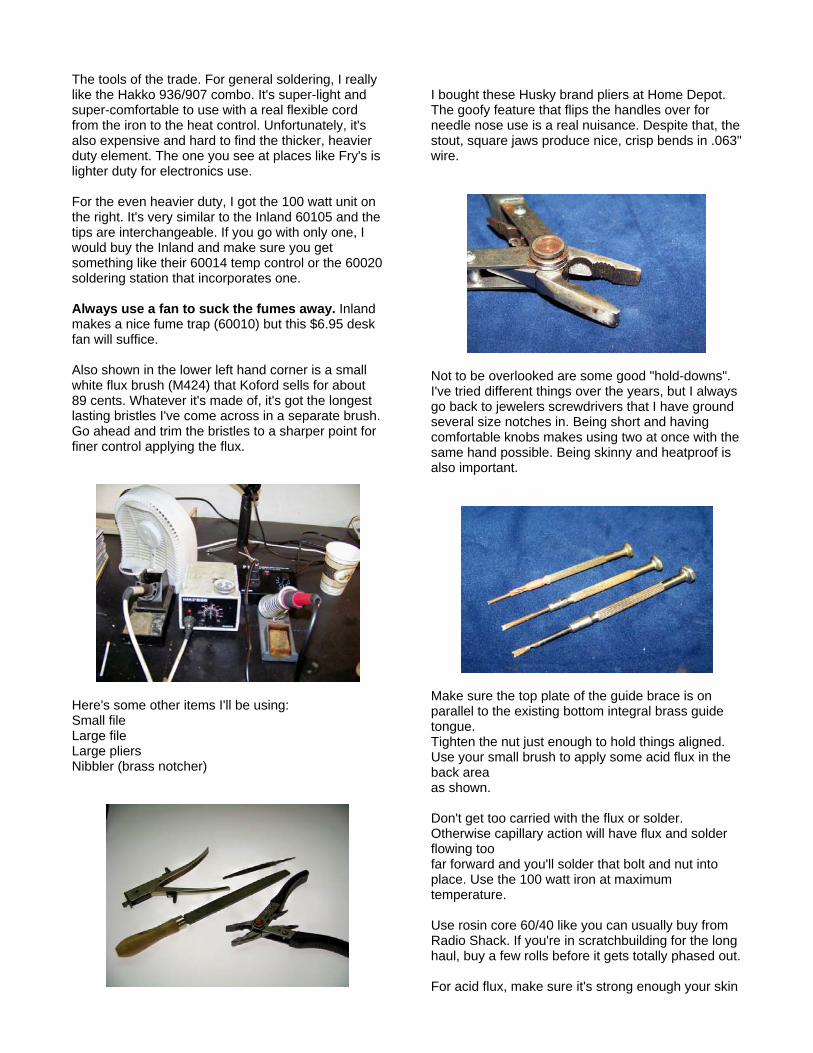
The tools of the trade. For general soldering, I really like the Hakko 936/907 combo. It's super-light and super-comfortable to use with a real flexible cord from the iron to the heat control. Unfortunately, it's also expensive and hard to find the thicker, heavier duty element. The one you see at places like Fry's is lighter duty for electronics use. For the even heavier duty, I got the 100 watt unit on the right. It's very similar to the Inland 60105 and the tips are interchangeable. If you go with only one, I would buy the Inland and make sure you get something like their 60014 temp control or the 60020 soldering station that incorporates one. Always use a fan to suck the fumes away. Inland makes a nice fume trap (60010) but this $6.95 desk fan will suffice. Also shown in the lower left hand corner is a small white flux brush (M424) that Koford sells for about 89 cents. Whatever it's made of, it's got the longest lasting bristles I've come across in a separate brush. Go ahead and trim the bristles to a sharper point for finer control applying the flux.
Here's some other items I'll be using: Small file Large file Large pliers Nibbler (brass notcher)
I bought these Husky brand pliers at Home Depot. The goofy feature that flips the handles over for needle nose use is a real nuisance. Despite that, the stout, square jaws produce nice, crisp bends in .063" wire.
Not to be overlooked are some good "hold-downs". I've tried different things over the years, but I always go back to jewelers screwdrivers that I have ground several size notches in. Being short and having comfortable knobs makes using two at once with the same hand possible. Being skinny and heatproof is also important.
Make sure the top plate of the guide brace is on parallel to the existing bottom integral brass guide tongue. Tighten the nut just enough to hold things aligned. Use your small brush to apply some acid flux in the back area as shown. Don't get too carried with the flux or solder. Otherwise capillary action will have flux and solder flowing too far forward and you'll solder that bolt and nut into place. Use the 100 watt iron at maximum temperature. Use rosin core 60/40 like you can usually buy from Radio Shack. If you're in scratchbuilding for the long haul, buy a few rolls before it gets totally phased out. For acid flux, make sure it's strong enough your skin

tingles when a bit gets on it. Use something at least as good as Stay-Clean. I also sell some that will have you hustling to the sink to wash it off even quicker.
Once cool, remove the nut and bolt. Now you can go back and touch up the front, adding flux and solder to the area around the pivot hole. Do one side at a time, allowing a little cooling time in between, so as not to disturb that first solder joint towards the back.
Since my four other rotary tools are hard-wired into another work area (so the cords don't tangle), I'll just use my heavy duty stuff for the polishing and cutting. On top is a Bosch variable speed trim router with a 2" diameter wire brush. It works real well but you have to be real careful you don't try to get in too tight of a corner or things go flying and stuff gets bent. Make sure you get a wheel fine enough it won't scratch the brass, but heavy enough to remove excess solder. Also, make triple-sure you have good eye protection and be prepared to catch some wire ends in your clothes and skin (especially when the wheel is new). I'll also show at the end of the article, a more expensive, but safer and less painful alternative for
removing solder. At the bottom is a Dremel Advantage. It's basically a low-end RotoZip. It's super-powerful and, at $39 when on sale at Menard's, is a great bargain. Combined with the Dremel EZ-Lock, large diameter, fiber-reinforced cutting discs, even 3/32" piano wire is a breeze to cut.
Neutralize the solder joint with some soapy water and a small rag or sponge. Clean off the excess solder with the wire wheel. Make sure you do it now before the axle gets soldered into place.
I'll be using approx. a 4.00" guide lead so the back of the pans will need to trimmed back a bit for tire clearance. I have the luxury of a finished chassis to "mirror up" to it to mark how much needs to be cut. You'll be removing about .150". This will leave the length of the pans as about 3.250" from the back edge to the BACK notch of the front wheel cut-out.

Even if you are very steady with your Dremel and a cutting disc, it will still need a bit of clean-up with a file when you're done. Thus, whenever I can use my nibbler to trim brass, I do. Less heat and less brass dust flying around. I prefer the relatively inexpensive, Taiwan-made model Radio Shack usually has. It cuts .032" brass like butter. Don't attempt to use it on .064".
A full "bite" is approximately .075" deep, so two of them will be just about perfect.
After smoothing out the nibbler cuts with a file, for aesthetics, check to see the end of the pans are fairly square and even.
The slots, IMO, are even a little tight for .063" wire, so they need to be opened up just a tad. I didn't have a .063" straight grinding burr handy, so I made do with a 1/16" drill bit. You'll need the 1/16" bit for later, anyway. Just run the rotating bit (perpendicular to the slot) back and forth, until the .063" wire rail will drop in flat, without any resistance.
For the 4" wheelbase we'll be using, shorten those gnarly ends of the .063" main rail approx. .093", squaring them off in the process. When done, stand the end of the rails on a flat block. Both rails should stand perpendicular/90 degrees to the block. If not, sand the long end slightly until it does. After a few attempts at tweaking it to lie flat, I went ahead and cut it in half in the back. This allowed each L-shaped side to lie nice, flat, and "relaxed". Shown is my left hand doing some contortions with four of my five fingers. Since I'm not using a jig, I'm holding the bracket with my middle finger and thumb while the index finger is holding down a notched screwdriver for the front of the rail and the other finger is keeping the back of the "L" from rotating up. After putting down the camera, I soldered the rail in the notch using the 100 watter. Obviously, repeat for the other side.
If you're careful applying the flux, you can get some fairly neat solder joints. I just concentrated on the inside as braces will be added later to the outside of the rails.
Let’s go ahead and reconnect the rails in back. I just used one of my pre-cut pieces of 1/16" brass tubing because the ends are perfectly square and burr-free.
After moving my hands out of the way, you can see the two pins I used to keep everything straight and symmetrical while soldering the rails back together. What did the job were cut-off ends of a couple of worn-out Falcon VII arms. If you look close, you can see the notches I put on the end of all my armature shafts to help "key" in solder to prevent pinions from
spinning. I can now slide the bracket between the rails, up and back, with the same snug, but fairly light resistance. We'll get back to installing the bracket a little later.
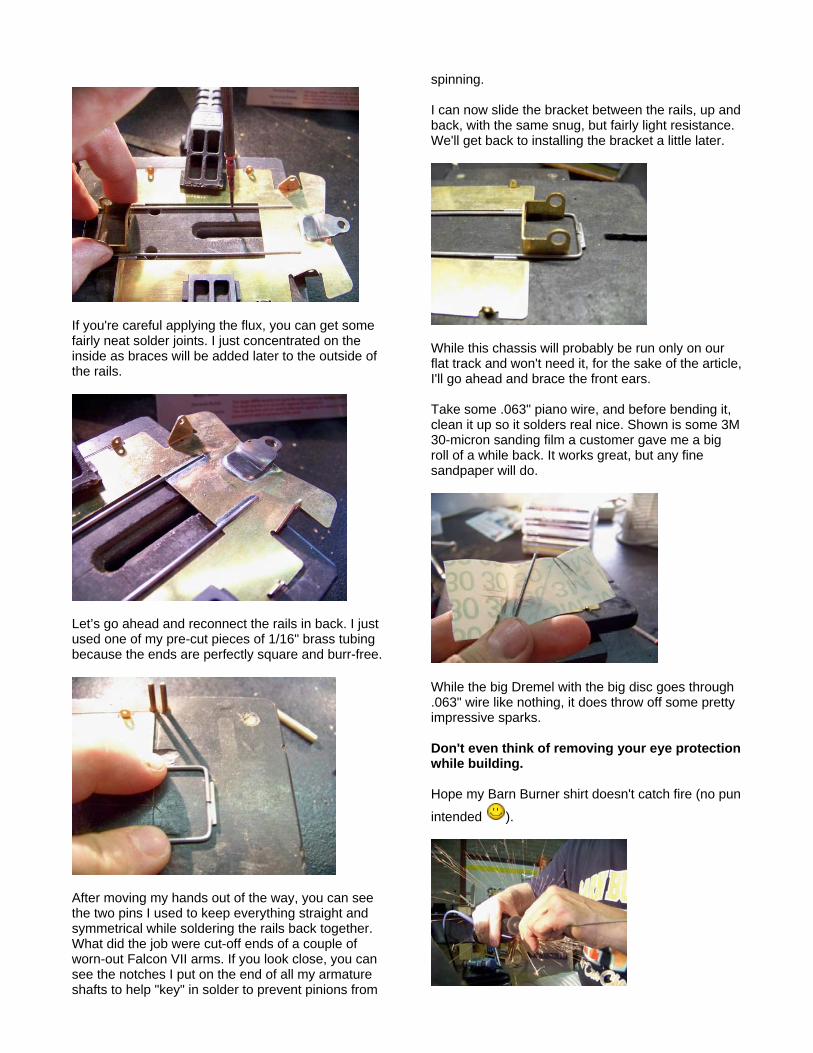
While this chassis will probably be run only on our flat track and won't need it, for the sake of the article, I'll go ahead and brace the front ears. Take some .063" piano wire, and before bending it, clean it up so it solders real nice. Shown is some 3M 30-micron sanding film a customer gave me a big roll of a while back. It works great, but any fine sandpaper will do.
While the big Dremel with the big disc goes through .063" wire like nothing, it does throw off some pretty impressive sparks. Don't even think of removing your eye protection while building. Hope my Barn Burner shirt doesn't catch fire (no pun
intended ).
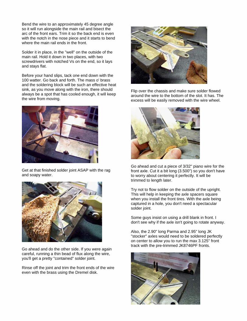
Bend the wire to an approximately 45 degree angle so it will run alongside the main rail and bisect the arc of the front ears. Trim it so the back end is even with the notch in the nose piece and it starts to bend where the main rail ends in the front. Solder it in place, in the "well" on the outside of the main rail. Hold it down in two places, with two screwdrivers with notched Vs on the end, so it lays and stays flat. Before your hand slips, tack one end down with the 100 watter. Go back and forth. The mass o' brass and the soldering block will be such an effective heat sink, as you move along with the iron, there should always be a spot that has cooled enough, it will keep the wire from moving.
Get at that finished solder joint ASAP with the rag and soapy water.
Go ahead and do the other side. If you were again careful, running a thin bead of flux along the wire, you'll get a pretty "contained" solder joint. Rinse off the joint and trim the front ends of the wire even with the brass using the Dremel disk.
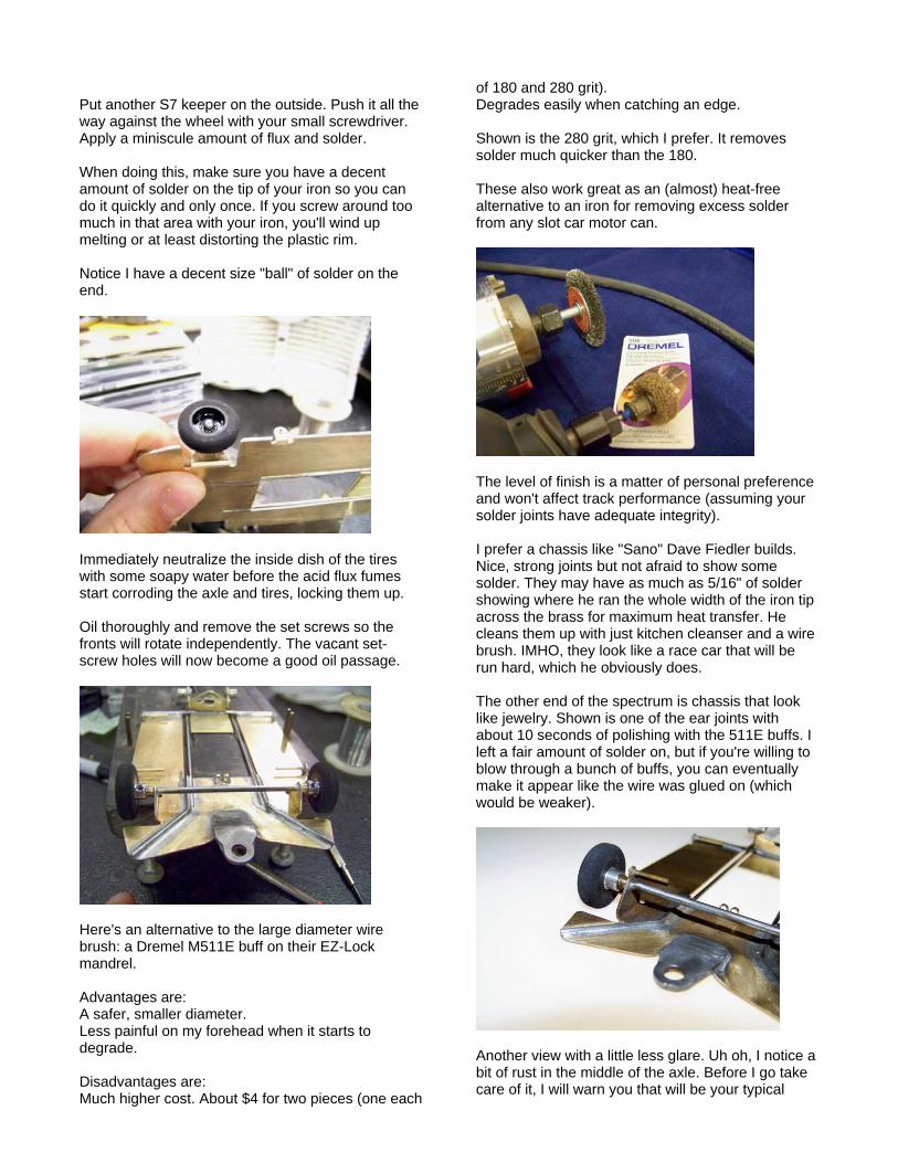
Flip over the chassis and make sure solder flowed around the wire to the bottom of the slot. It has. The excess will be easily removed with the wire wheel.
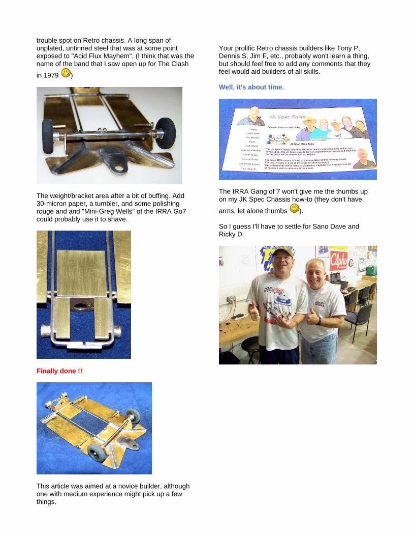
Go ahead and cut a piece of 3/32" piano wire for the front axle. Cut it a bit long (3.500") so you don't have to worry about centering it perfectly. It will be trimmed to length later. Try not to flow solder on the outside of the upright. This will help in keeping the axle spacers square when you install the front tires. With the axle being captured in a hole, you don't need a spectacular solder joint. Some guys insist on using a drill blank in front. I don't see why if the axle isn't going to rotate anyway. Also, the 2.90" long Parma and 2.95" long JK "stocker" axles would need to be soldered perfectly on center to allow you to run the max 3.125" front track with the pre-trimmed JK8746PF fronts.

The JK bracket is designed to be used with a 7/32" axle tube. It's just a tad tight. An Irwin Unibit with 1/32" increments works great for this and any other application where you need to open up an existing hole. In the case of the JK, you can just rotate the chuck by hand to open it up. Any kind of straight burr that will fit in the hole will also work. Just grind a tiny bit until the tube fits.
I painted the 1/4" band with armature stack/layout dye as a "warning" so I don't open it up too far.
I used one of my 1.400" pre-cut axle tubes and moved it back and forth until it appeared centered. I confirmed this with my calipers and lightly tacked in one side in case I accidently moved it and it had to be readjusted. Once I reconfirmed it was OK, I soldered the other side. I changed from side to side, each time, making sure the other side was cool, until I had nice smooth fillets of solder on both sides.
A .0005" diff is way better than close enough.
The 1.400" axle tube was designed for BBs or when the Champion flatside oilites were available. If you use an oilite with a nub, it will need to be ground off so you can squeeze in at least one thin axle spacer per side. I put the oilite on an axle and slowly feed it up into a spinning Dremel disk with my thumbnail. The disk will catch the nub and start spinning the oilite, trimming it pretty dead-on square.
The enclosed tube makes using a spring as a bushing alignment aid impractical. Still the perfectly square ends of a factory-cut tube makes installing the bearings straight and aligned a pretty easy task.

Now, on to installing the bracket without a jig. With the nice fit I had between the bracket and the main rails, it was way easier than I expected. I set the calipers to 3.906" (approximately 4" minus half the diameter of a 3/32" axle times two). I put an axle in the bracket and pushed it forward until both the front and rear axle touched the inner tangs of the calipers on the left side of the chassis. I tack-soldered the bracket on that that side to the frame rail. I checked the other (right) side and the calipers touched both axles on that side with the same amount of pressure as the other. I tack-soldered that side in and confirmed by now measuring on the outside of the axles. 4.0925" on both sides brings the wheelbase in at .00125" short of 4". Note: the bracket is at the right height so it doesn't require jig wheels. Just make sure both sides are soldered flat and even on the block. I went back and resoldered the whole length of the bracket on both sides, doing the back and forth method, making sure one side had cooled before I reheated the other.
With the car being intended for a flat track, I went ahead and packed some more weight in the back. I used .064 X 1/4" wide brass. The nibbler doesn't like .064" and I wanted to get it square, so I pulled out the miter box and a razor saw. Using Zona Saw #0001 with "duller than dull" teeth turned out to be the most arduous part of this build.
The inner corners of the weights will have to be rounded to fit flush/conform to the inside radius of the bend in the bracket. You'll also have to cut the middle of the axle tube out so you can more easily install the weights. Use a smaller diameter Dremel disk to aid in not cutting the bracket or top of the main rails in back. Cut it a little bit at a time, dipping it in water often to cool it, so you don't disturb the solder joints and screw up your alignment. Leave approximately 1/16" of the tube sticking out the inside of the bracket. When soldering those thick weights, you'll have to use a fair amount of flux and heat. Use the 100 watter but be careful not to shift the bracket out of alignment.

Flip the chassis over to check if the solder flowed adequately to the bottom side. Once satisfied, wire brush it if necessary and rinse thoroughly with soapy water.
We'll also be adding a weight to the front of the bracket. It will fit under the motor as I am using a standard, non-hypoid bracket. While it won't be as effective as a finned aluminum model, it will also act a low profile heat-sink. Use a piece of 1" wide X .032" thick brass. Set your calipers to .920" wide and use the outer tangs to scribe a line on the brass.
Trim it with your nibbler or Dremel and smooth out the cut edge. Center and install it with the .920" dimension inside the rails as not to interfere with the flex. Don't be afraid to also try it turned 90 degrees and soldered to the rails. That's part of the fun with these
scratchbuilt cars; the infinite ways you can fine tune them and the resulting handling differences. Use the 100 watter, and quickly, as not to affect all the solder joints nearby. Easy on the flux, making sure none of the solder interferes with your motor installation.
I slipped a 29t (the biggest) crown gear on an axle and checked that it clears the weights and back of the main rail.

While we want the pans to go up and twist a bit, tests show allowing any side play will make the car twitch in the back or appear to be loose or slimy. We'll make some side "L" stops from .063" wire bent to 90 degrees. If you want it to lie nice and flat on the pan, you'll need to give it an additional little tweak right at the 90 degree bend, on the span that goes to the pan, not the bracket. This will be the only component of the car that requires more than one bend. The down stops are also .063" wire, bent less than 10 degrees. Installing two pieces of wire in the same spot is bit tricky but it's a ton easier if you use the right sequence. Remember to first clamp both pans flat on the block. I didn't get a correct pic but on the side towards the rear tires, tack solder both side stops into place, using just a tiny bit of flux, making sure no appreciable amount of solder flows forward of the wire. If it does, remove it with solder-wick or a piece of braid with flux on the end. Make sure you just solder the "L" to the pan, not the bracket. Avoid the temptation to try it solid. Take my word, it just doesn't work. Double-check you have successfully eliminated any side pan movement and move on to the down stops. Use your notched screwdriver to hold the down stop wire against the side stops. Both should be touching each other the whole width of the pan. Let the short angled portion rotate/fall forward until it touches the main rails. Make sure the inside end is about 1/16th" away from the motor can or it will prevent the up/twisting movement. Tack solder it quickly towards the front, furthest away from where you tack soldered the side stops. Unclamp the chassis from the block and check that the up stops prevent the pans from dropping below the main rails and don't hold them up above the main rails, either. Reclamp the chassis and finish soldering the double wire assembly on both sides. Again, use the back and forth method, using the quick cooling of the brass as your "friend".
Trim the excess wire off with your cutting disc and clean with soapy water, as always. Since I'm not using a jig that might indicate the width, I better check it. Oops, it tapers out a bit wide in the back. It'll have to be fixed.
Carefully file the sides a tiny bit on both sides until you just get under the 3.125" maximum width.

All four holes on the pin tube uprights are just a tad tight, so use that 1/16" drill bit to open them up.
Here's the simple rig I use to install and align the pin tubes. It consists of a pc. of .032 wire, preferably one that is a bit rusty to resist being soldered to. A piece of 1/16th" tubing is soldered on the end and is used to push against a .032 thick pc. of brass strip with a hole in it for the wire to pass through.
Some builders like to angle their pin tubes down so the inside can be soldered to the pan. I prefer to keep them straight so the whole inside of pin head is up against the body. For a little more strength, I add a Koford M536 1/16th" brass keeper on the inside of the pin tube upright for a little more surface area to solder to. I've removed my hand and the clamp for this pic. I clamp the pan even with the edge of the block. I then hold the brass strip against the side of the block. Before soldering, the pin tube is pushed against the inside of the brass strip which will keep it even with the outside edge of the pan.
While you got the 1/16" drill out, go ahead and use it to put a small chamfer on the end of the brass pin tube. This will make it much easier to pin the body back on, especially as we get a bit older and our eyes aren't quite as sharp.
If your eyes are still pretty good, you can spot the tapered lead-in.
Don't forget to install a lead wire holder. It's just an earring back. Before 1989, guys used a piece of round brass tubing, crimped into an oval, or didn't use one at all. I first spotted one on "Punk" Tony's car, a local Chicago racer, who worked for Koford a short while. When I told Stu, he loved the idea, bought them from a local jewelry supplier, and we started including them in chassis kits and on RTR chassis. Pretty soon Zap was buying them from us and it became the standard.

I just held it down with a screwdriver and ran a bit of flux in from the backside edge of the nose piece. I fed the solder in from that same back edge as not to get solder all over the place. I went a little bit heavy on the solder, but you're always better off with a bit more than not enough.
Before installing the fronts, I'm going to go ahead and clean the chassis up real well, using two old standbys, kitchen cleanser and a wire brush. I also used some of that 3M 30-micron polishing film I refer to earlier. When I found the Old Dutch under the kitchen sink, I thought I had scored some vintage cleanser to clean up the Retro ride. I was bummed when I spotted a bar code on the side.
Of course, Noose would be out front making sure everything is legal.
Noose looks like his moustache fell victim to Chicagoland Raceway acid flux while some of the other IRRA Go7 reflect on my work, especially Tony
and Ron. Install the front wheels. I used the JK8746PF which are a bit oversize (about .780") so you'll have legal front clearance without opening up the axle hole in the upright or having to set the axle height using jig wheels. I was able to use a Slick 7 S7-22 .024" steel spacer and a S7-148 3/32" brass keeper (unsoldered) on each side. That combo left a tiny bit of side play when I temporarily tightened the front tires down to about .005-.010" under the max legal tire width of 3.125".
Put another S7 keeper on the outside. Push it all the way against the wheel with your small screwdriver. Apply a miniscule amount of flux and solder. When doing this, make sure you have a decent amount of solder on the tip of your iron so you can do it quickly and only once. If you screw around too much in that area with your iron, you'll wind up melting or at least distorting the plastic rim. Notice I have a decent size "ball" of solder on the end.
Immediately neutralize the inside dish of the tires with some soapy water before the acid flux fumes start corroding the axle and tires, locking them up. Oil thoroughly and remove the set screws so the fronts will rotate independently. The vacant set-screw holes will now become a good oil passage.
Here's an alternative to the large diameter wire brush: a Dremel M511E buff on their EZ-Lock mandrel. Advantages are: A safer, smaller diameter. Less painful on my forehead when it starts to degrade. Disadvantages are: Much higher cost. About $4 for two pieces (one each
of 180 and 280 grit). Degrades easily when catching an edge. Shown is the 280 grit, which I prefer. It removes solder much quicker than the 180. These also work great as an (almost) heat-free alternative to an iron for removing excess solder from any slot car motor can.
The level of finish is a matter of personal preference and won't affect track performance (assuming your solder joints have adequate integrity). I prefer a chassis like "Sano" Dave Fiedler builds. Nice, strong joints but not afraid to show some solder. They may have as much as 5/16" of solder showing where he ran the whole width of the iron tip across the brass for maximum heat transfer. He cleans them up with just kitchen cleanser and a wire brush. IMHO, they look like a race car that will be run hard, which he obviously does. The other end of the spectrum is chassis that look like jewelry. Shown is one of the ear joints with about 10 seconds of polishing with the 511E buffs. I left a fair amount of solder on, but if you're willing to blow through a bunch of buffs, you can eventually make it appear like the wire was glued on (which would be weaker).
Another view with a little less glare. Uh oh, I notice a bit of rust in the middle of the axle. Before I go take care of it, I will warn you that will be your typical
trouble spot on Retro chassis. A long span of unplated, untinned steel that was at some point exposed to "Acid Flux Mayhem". (I think that was the name of the band that I saw open up for The Clash
in 1979 )
The weight/bracket area after a bit of buffing. Add 30-micron paper, a tumbler, and some polishing rouge and and "Mini-Greg Wells" of the IRRA Go7 could probably use it to shave.
Finally done !!
This article was aimed at a novice builder, although one with medium experience might pick up a few things.
Your prolific Retro chassis builders like Tony P, Dennis S, Jim F, etc., probably won't learn a thing, but should feel free to add any comments that they feel would aid builders of all skills. Well, it's about time.
The IRRA Gang of 7 won't give me the thumbs up on my JK Spec Chassis how-to (they don't have
arms, let alone thumbs ). So I guess I'll have to settle for Sano Dave and Ricky D.