A European Design Code for Pallet Racking
22
Fourteenth International Specialty Conference on Cold-Fonned Steel Structures St. Louis, Missouri U.S.A., October 15-16,1998 A European Design Code for Pallet Racking J. M. Davies' and M.H.R. Godley2 Summary The work leading to a European design code for pallet racking started almost 25 years ago. Many difficulties were encountered in the early days of this work. Notable were the absence of a consistent safety philosophy between the various countries of Europe and the existence of procedures with which the manufacturers were comfortable but which were potentially unsafe. There were also difficulties in defining acceptable standard. test procedures. The emergence of Eurocode 3, especially Part 1.3 dealing with cold formed sections, provided a new inlpetus to the work because here was a European code which provided the required basis for the design code. Accordingly, Section X of the Federation Europeenne de la Manutention (FEM) commissioned technical "experts" to draft the new code under the direction of its technical committee. It was a requirement that the code should be, as far as possible, compatible with Eurocode 3. In the early stages of the work, there were a group of these experts but, for most of the drafting period, only the authors of this paper were active. The code was essentially complete in mid 1997 and, since then, it has been subject to trial use by the member companies of FEM and open to consequential comments. However, in May 1997, a significant meeting took place. FEM and the Rack Manufacturers Institute (RMI) of the USA sponsored a meeting between the first author and RMI's own "expert", Professor T Pekoz of Cornell University. The intention was to compare the two codes and to report on the potential for possible future harmonisation. It emerged that the two codes were about as different as two codes covering the design of the same structural elements could be! However, the "experts" took a positive view of the situation and concluding that, from the technical point of view, there was no reason why the two codes could not be brought into convergence and that, in the meantime, we could each learn from the others experience. Consequently, at this late stage in the evolution of the European code, a number of significant changes were made where it was considered that the European code could advantageously be made more compatible with the RMI code without in any way impairing its technical rigour. This paper introduces the new European design code for pallet racking and compares and contrasts it with its American counterpart. As a pallet rack is a particularly demanding application of cold-formed steel sections, it is hoped that the designers of other cold-formed products may also learn from some of the approaches described in this paper. 1 School of Engineering, University of Manchester, Manchester M13 9PL, England. 2 School of Construction & Earth Sciences, Oxford Brookes University, Oxford OX3 OBP, England. 289
Transcript of A European Design Code for Pallet Racking
Fourteenth International Specialty Conference on Cold-Fonned Steel Structures St. Louis, Missouri U.S.A., October 15-16,1998
A European Design Code for Pallet Racking
J. M. Davies' and M.H.R. Godley2
Summary
The work leading to a European design code for pallet racking started almost 25 years ago. Many difficulties were encountered in the early days of this work. Notable were the absence of a consistent safety philosophy between the various countries of Europe and the existence of procedures with which the manufacturers were comfortable but which were potentially unsafe. There were also difficulties in defining acceptable standard. test procedures.
The emergence of Eurocode 3, especially Part 1.3 dealing with cold formed sections, provided a new inlpetus to the work because here was a European code which provided the required basis for the design code. Accordingly, Section X of the Federation Europeenne de la Manutention (FEM) commissioned technical "experts" to draft the new code under the direction of its technical committee. It was a requirement that the code should be, as far as possible, compatible with Eurocode 3. In the early stages of the work, there were a group of these experts but, for most of the drafting period, only the authors of this paper were active.
The code was essentially complete in mid 1997 and, since then, it has been subject to trial use by the member companies of FEM and open to consequential comments. However, in May 1997, a significant meeting took place. FEM and the Rack Manufacturers Institute (RMI) of the USA sponsored a meeting between the first author and RMI's own "expert", Professor T Pekoz of Cornell University. The intention was to compare the two codes and to report on the potential for possible future harmonisation.
It emerged that the two codes were about as different as two codes covering the design of the same structural elements could be! However, the "experts" took a positive view of the situation and concluding that, from the technical point of view, there was no reason why the two codes could not be brought into convergence and that, in the meantime, we could each learn from the others experience.
Consequently, at this late stage in the evolution of the European code, a number of significant changes were made where it was considered that the European code could advantageously be made more compatible with the RMI code without in any way impairing its technical rigour.
This paper introduces the new European design code for pallet racking and compares and contrasts it with its American counterpart. As a pallet rack is a particularly demanding application of cold-formed steel sections, it is hoped that the designers of other cold-formed products may also learn from some of the approaches described in this paper.
1 School of Engineering, University of Manchester, Manchester M13 9PL, England. 2 School of Construction & Earth Sciences, Oxford Brookes University, Oxford OX3 OBP,
England. 289
290
Introduction
In many respects, pallet racking represents one of the ultimate challenges in structural engineering design. A typical pallet rack may be viewed as being similar to a slender multistorey building in which the beams and columns are cold-formed sections. Spice is added to the design process by the fact that it is fairly certain that the full design load will be achieved and there are no benefits to be obtained from secondary structural elements such as cladding and partitions.
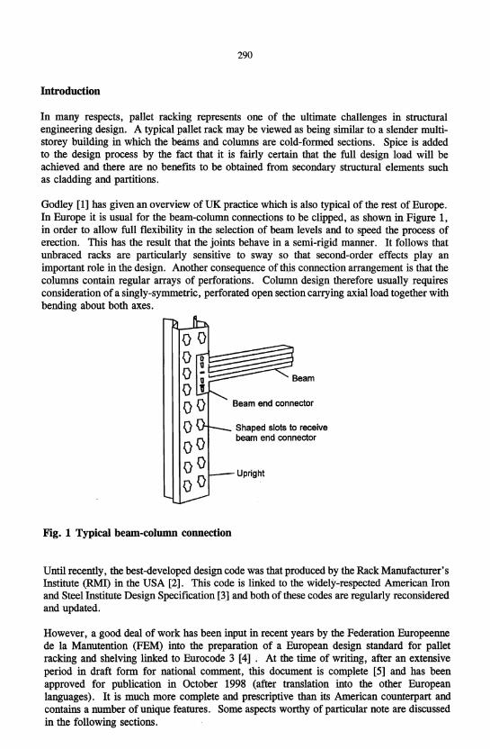
Godley [1] has given an overview of UK practice which is also typical of the rest of Europe. In Europe it is usual for the beam-column connections to be clipped, as shown in Figure 1, in order to allow full flexibility in the selection of beam levels and to speed the process of erection. This has the result that the joints behave in a semi-rigid manner. It follows that unbraced racks are particularly sensitive to sway so that second-order effects play an important role in the design. Another consequence of this connection arrangement is that the columns contain regular arrays of perforations. Column design therefore usually requires consideration of a singly-symmetric, perforated open section carrying axial load together with bending about both axes.
Fig. 1 Typical beam-column connection
Beam end connector
Shaped slots to receive beam end connector
Upright
Until recently, the best-developed design code was that produced by the Rack Manufacturer's Institute (RMI) in the USA [2]. This code is lirlked to the widely-respected American Iron and Steel Institute Design Specification [3] and both of these codes are regularly reconsidered and updated.
However, a good deal of work has been input in recent years by the Federation Europeenne de la Manutention (FEM) into the preparation of a European design standard for pallet racking and shelving linked to Eurocode 3 [4]. At the time of writing, after an extensive period in draft form for national comment, this document is complete [5] and has been approved for publication in October 1998 (after translation into the other European languages). It is much more complete and prescriptive than its American counterpart and contains a number of unique features. Some aspects worthy of particular note are discussed in the following sections.
291
Load and material factors
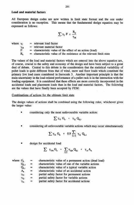
All European design codes are now written in limit state format and the one under consideration is no exception. This means that the fundamental design equation may be expressed as follows:
where 'Yf
'YM F Rk
relevant load factor relevant material factor characteristic value of the effect of an action (load) characteristic value of the resistance at the relevant limit state
The values of the load and material factors which are entered into the above equation are, of course, crucial to the safety and economy of the design and have been subject to a great deal of debate. Central to this debate is the consideration that the statistical variability of pallet loads is quite different from that of wind, snow and floor loads which constitute the primary live load cases considered in Eurocode 3. Another important principle is that the main uncertainty in the load-related performance of a pallet rack is in the interaction with the loading equipment. It is considered that these effects are more correctly incorporated in the accidental loads and placement loads than in the load and material factors. The following are the values that have finally been accepted by FEM:
Combinations of actions for the ultimate limit state
The design values of actions shall be combined using the following rules, whichever gives the larger value:
• considering only the most unfavourable variable action:
• considering all unfavourable variable actions which may occur simultaneously
LYG Gk + 0.9 ~1 YQ Qk,i
• design for accidental load
where Gk
Qk,l
Qk.i
Ak
'YG 'YQ 'YA
L Y GA Gk + L Y QA Qk,i + Y A Ak hI
characteristic value of a permanent action (dead load) characteristic value of one of the variable actions characteristic value of a typical variable action characteristic value of an accidental action partial safety factor for permanent actions partial safety factor for variable actions partial safety factor for accidental actions
292
Combination of actions for the serviceability limit states
• considering only the most unfavourable variable action
LyGGk + YQQk,l
• considering all unfavourable variable actions
where the notation is defined above.
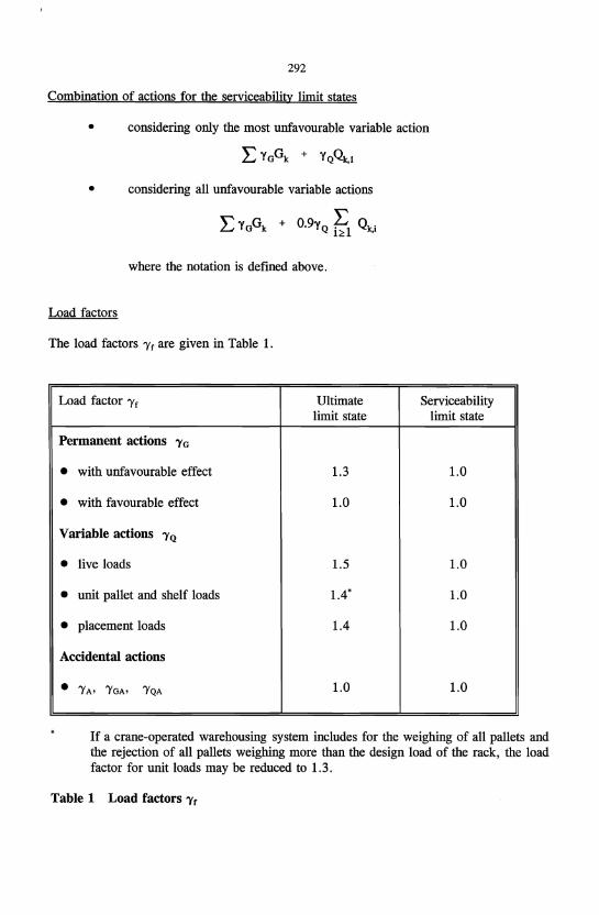
Load factors
The load factors 'Yf are given in Table 1.
Load factor 'Y f Ultimate Serviceability limit state limit state
Permanent actions 'YG
• with unfavourable effect 1.3 1.0
• with favourable effect 1.0 1.0
Variable actions 'YQ
• live loads 1.5 1.0
• unit pallet and shelf loads 1.4' 1.0
• placement loads 1.4 1.0
Accidental actions
• 'YA' 'YGA> 'YQA 1.0 1.0
If a crane-operated warehousing system includes for the weighing of all pallets and the rejection of all pallets weighing more than the design load of the rack, the load factor for unit loads may be reduced to 1.3.
Table 1 Load factors 'Yr
293
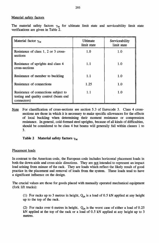
Material safety factors
The material safety factors 'YM for ultimate limit state and serviceability limit state verifications are given in Table 2.
Material factor 'YM Ultimate Serviceability limit state limit state
Resistance of class 1, 2 or 3 cross- 1.0 1.0 sections
Resistance of uprights and class 4 1.1 1.0 cross-sections
Resistance of member to buckling 1.1 1.0
Resistance of connections 1.25 1.0
Resistance of connections subject to 1.1 1.0 testing and quality control (beam end connectors)
Note For classification of cross-sections see section 5.3 of Eurocode 3. Class 4 crosssections are those in which it is necessary to make specific allowances for the effects of local buckling when determining their moment resistance or compression resistance. In general, cold-formed steel uprights, because of all kinds of difficulties, should be considered to be class 4 but beams will generally fall within classes 1 to 3.
Table 2 Material safety factors 'YM
Placement loads
In contrast to the American code, the European code includes horizontal placement loads in both the down-aisle and cross-aisle directions. They are not intended to represent an impact load arising from misuse of the rack. They are loads which reflect the likely result of good practice in the placement and removal of loads from the system. These loads tend to have a significant influence on the design.
The crucial values are those for goods. placed with manually operated mechanical equipment (fork lift trucks):
(1) For racks up to 3 metres in height, Qph is a load of 0.5 kN applied at any height up to the top of the rack.
(2) For racks over 6 metres in height, Qph is the worst case of either a load of 0.25 kN applied at the top of the rack or a load of 0.5 kN applied at any height up to 3 metres.
294
(3) for racks with heights between 3 and 6 metres, Qph is the worst case of a load at the top of the rack whose magnitude is deternlined by linear interpolation between (1) and (2) or a load of 0.5 k:N applied at any height up to 3 metres.
Some rules are given for a conservative treatment of the above spectrum of loads whereby the number of load cases may be significantly reduced.
Second-order analysis of slender frames with semi-rigid joints
Pallet rack structures are probably unique in that they are framed structures that are regularly designed in such a way that the ultimate limit state may be close to the elastic critical load. This has required special consideration of the treatment of second-order effects and novel procedures have been devised to deal with this [6]. These are in harmony with the basic philosophy of Eurocode 3. .
Crucial to the treatment of second-order effects is the necessity for a reliable estinlate of the elastic critical load Vcr of the rack for failure in a sway mode. Two alternative methods are offered for down aisle stability and one for cross aisle stability. Frame classification is then based on the ratio VsiVcr where VSd is the design value of the vertical load on the frame.
(1) IfVsiVcr ::;; 0.1, a frame may be classified as non-sway, i.e. its response to in-plane horizont<!l forces is sufficiently stiff for it to be acceptably accurate to neglect any additional internal forces or moments arising from horizontal displacement of the nodes. In such a case, a first-order analysis is sufficient.
Any other frame shall be classified as a sway frame and the effects of the horizontal displacement of its nodes taken into account in its design. Unbraced racks are invariably classed as sway frames in the down-aisle direction and therefore require consideration of second-order effects.
(2) If 0.1 < VsiVcr ::;; 0.3, a level 2 analysis may be used in which second-order effects are treated approximately (eg according to Reference [6]).
(3) If VsiVcr > 0.3, a level 1 analysis is required in which second-order effects are treated directly.
Note: The limit at which an accurate second-order analysis becomes mandatory is more generous than that in Eurocode 3. This is because pallet racks have semi-rigid joints and generally have a regular construction. In these circumstances, the agreement between the exact and approximate methods is much improved so that the range of validity of the approxinlate methods may be increllsed.
Testing philosophy and the treatment of test results
Design philosophy
The European design code is based on a philosophy of rational analysis assisted by testing. The market for storage products such as pallet racking is highly competitive and efficient structural performance is at a premium. This can often be most easily achieved by testing
295
critical components which are difficult to analyses or whose analysis may rely on conservative assumptions in order to ensure that acceptable standards of safety are maintained. Thus, the primary purpose of testing is to provide the designer with realistic information about the performance, usually strength and stiffness, of components of the structure.
Quality assurance
However, testing is also used to provide quality assurance during production and, for this purpose, two tests are specified. These are perceived to be crucial to the maintenance of quality in production. The structural performance of pallet racks is heavily dependant on the behaviour of the connection between the beam and the upright, usually termed the beam end connector in European parlance. This is particularly so in the case ofunbraced racks which form the majority of installations. Hence, manufacturers are required to make tests on these connections on a regular basis as a part of their quality assurance. Tool wear, variation in material properties and detailed design changes are all seen as potential causes of significant change in the mechanical performance of the beam end connector which thus requires regular monitoring.
The second quality assurance test is only of concern to those manufacturers who use the enhanced mechanical properties obtained by cold reducing steel strip prior to perforating and cold rolling. It is well known that cold reducing can substantially increase the yield stress of a carbon steel and that this increase is at the cost of a reduction in ductility to levels which may be below those that are generally specified in recognised standards. In order to ensure that such material is suitable for the manufacture of the components of pallet racks, a tensile test is used to determine the yield stress accompanied by a bend test designed to ensure that the ductility of the cold reduced material remains adequate.
Overview of test regime
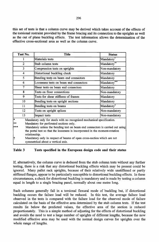
In addition to these quality assurance tests, the European design code lists a total of 13 tests which may be used in the design of pallet racks. Qf these, 9 are mandatory in some or all circunlstances. Table 3 shows a list of these tests and the conditions under which they may be compulsory.
Tests on uprights
Three of the tests in Table 3 are compression tests on uprights. The stub colunm test is made in order to determine the effective area of the perforated upright and maybe carried out in one of two alternative ways. In the first, a short length of upright section is loaded in compression through ball bearings which provide a pinned connection with a well-defined line of action of the load. This approach, which is the traditional way of carrying out the stub-colunm test in Europe, requires that the optimum line of action of the load be determined by a process of trial and error. The alternative method is to test between flat ends using an arrangement similar to that specified by the RMI [2]. Recent research by Pu et al [12] shows that the two methods give nearly identical results.
In the second set of upright compression tests, the stub column test series is extended to allow a column curve to be determined experimentally. Pallet rack systems normally employ braced frames with a fixed gate and these tests are made on a range of upright lengths in increments of a half or a full bracing gate depending on the bracing pattern. The merit of
296
this set of tests is that a column curve may be derived which takes account of the effects of the torsional restraint provided by the frame bracing and its connection to the uprights as well as the out of plane buckling effects. The test information allows the determination of the effective cross-sectional area as well as the column curve.
Test No. Title Status I Materials tests Mandatory
,
2 Stub column tests Mandatory .. 3 Compression tests on uprights Non-mandatory 4 Distortional buckling check Mandatory
5 Bending test,s on beam end connectors Mandatory 6 Looseness tests on beam end connectors Mandatory'"
7 Shear tests on beam end connectors Mandatory 8 Tests on floor connections Non-mandatory
9 Tests for shear stiffness of frames Mandatory
10 Bending tests on upright sections Mandatory
11 Bending tests on beams Mandatory!
12 Tests on upright splices Non-mandatory
13 Impact tests Non-mandatory
* Mandatory only for steels with no recognised mechanical specification.
** Mandatory for perforated sections only.
*** Mandatory unless the bending test on beam end connectors is carried out using the portal test so that the looseness is incorporated in the moment-rotation relationship.
t Mandatory only in respect of beams of open cross-section which are not symmetrical about a vel1ical axis.
Table 3 Tests specified in the European design code and their status
If, alternatively, the column curve is deduced from the stub column tests without any further testing, there is a risk that any distortional buckling effects which may be present could be ignored. Many pallet rack uprights, because of their relatively wide unstiffened or partly stiffened flanges, appear to be particularly susceptible to distortional buckling effects. In these circumstances, a check for distortional buckling is mandatory and is made by testing a column equal in length to a single bracing panel, normally about one metre long.
Such columns generally fail in a torsional flexural mode of buckling but, if distortional buckling occurs the failure load will be reduced. In this test, the average failure load observed in the tests is compared with the failure load for the observed mode of failure calculated on the basis of the effective area determined by the stub column tests. If the test results lie below the predicted values, the effective area of the section is reduced proportionately. This is a simple method of adjusting for the effects of distortional buckling and avoids the need to test a large number of uprights of different lengths, because the now modified effective area may be used with the normal design curves for uprights over the whole range of lengths.
297
Tests on beam end connectors
Another group of three tests is concerned with the performance of the beam end connector. The critical properties of the connector are stiffness, bending strength and looseness. Shear strength is also important and a simple test is specified for this. However, for many connectors, shear strength is not often a limiting factor.
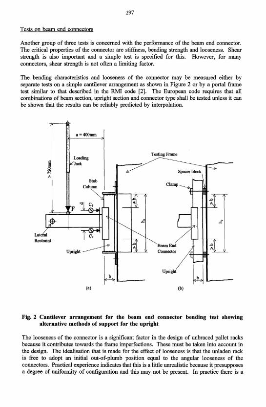
The bending characteristics and looseness of the connector may be measured either by separate tests on a simple cantilever arrangement as shown in Figure 2 or by a portal frame test similar to that described in the RMI code [2]. The European code requires that all combinations of beam section, upright section and connector type shall be tested unless it can be shown that the results can be reliably predicted by interpolation.
Latei'al Restraint
a=400mm
Loading Jack
F
Stub
(a)
_~:une
~ Spacer block
Beam End Connector
Upright
(b)
Fig. 2 Cantilever arrangement for the beam end connector bending test showing alternative methods of support for the upright
The looseness of the connector is a significant factor in the design of unbraced pallet racks because it contributes towards the frame imperfections. These must be taken into account in the design. The idealisation that is made for the effect of looseness is that the unladen rack is free to adopt an initial out-of-plumb position equal to the angular looseness of the connectors. Practical experience indicates that this is a little unrealistic because it presupposes a degree of uniformity of configuration and this may not be present. In practice there is a
298
range of loosenesses present in any batch of COlmectors in a given rack and the effects of small errors in the way that the connector is welded to the beam, the lack of straightness of the members of the rack and errors in the pitching and grouping of the perforations all tend to mutually interfere and suppress the slackness in the rack which is the consequence of this idealisation.
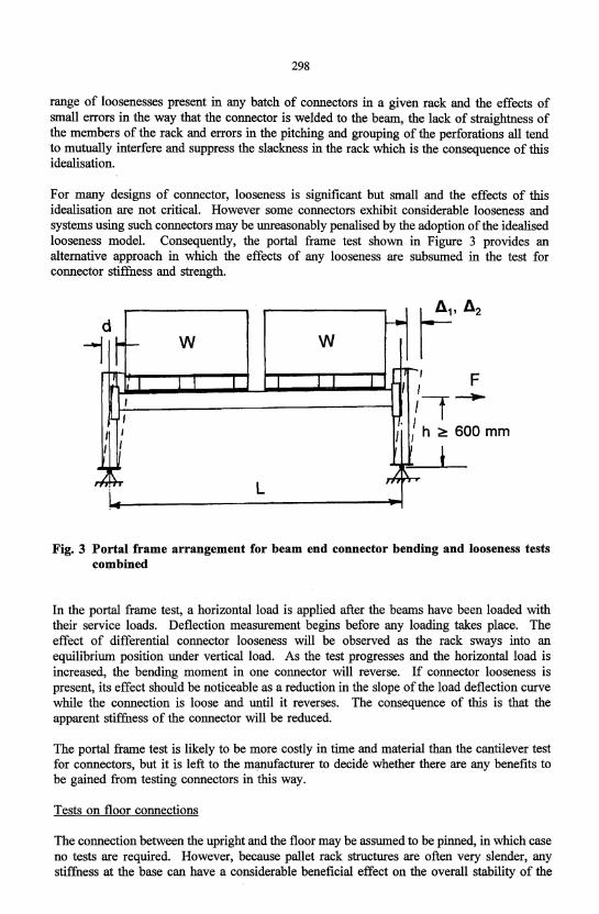
For many designs of connector, looseness is significant but small and the effects of this idealisation are not critical. However some connectors exhibit considerable looseness and systems using such connectors may be unreasonably penalised by the adoption of the idealised looseness model. Consequently, the portal frame test shown in Figure 3 provides an alternative approach in which the effects of any looseness are subsumed in the test for connector stiffness and strength.
d I--' f' I r- W W
-, '1 I I I _L I I J I I I
I
I '1 I . I I I J , h ?! 6 I I
t 00 mm
~i~ L ,I, ~
Fig. 3 Portal frame arrangement for beam end connector bending and looseness tests combined
In the portal frame test, a horizontal load is applied after the beams have been loaded with their service loads. Deflection measurement begins before any loading takes place. The effect of differential connector looseness will be observed as the rack sways into an equilibrium position under vertical load. As the test progresses and the horizontal load is increased, the bending moment in one connector will reverse. If connector looseness is present, its effect should be noticeable as a reduction in the slope of the load deflection curve while the connection is loose and until it reverses. The consequence of this is that the apparent stiffness of the connector will be reduced.
The portal frame test is likely to be more costly in time and material than the cantilever test for connectors, but it is left to the manufacturer to decide whether there are any benefits to be gained from testing connectors in this way.
Tests on floor connections
The connection between the upright and the floor may be assumed to be pinned, in which case no tests are required. However, because pallet rack structures are often very slender, any stiffness at the base can have a considerable beneficial effect on the overall stability of the
299
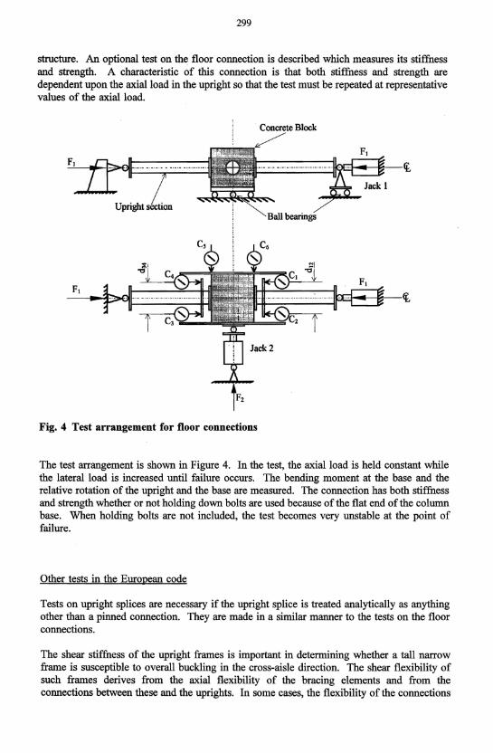
structure. An optional test on the floor connection is described which measures its stiffness and strength. A characteristic of this connection is that both stiffness and strength are dependent upon the axial load in the upright so that the test must be repeated at representative values of the axial load.
Block
Fig. 4 Test arrangement for floor connections
The test arrangement is shown in Figure 4. In the test, the axial load is held constant while the lateral load · is increased until failure occurs. The bending moment at the base and the relative rotation of the upright and the base are measured. The connection has both stiffness and strength whether or not holding down bolts are used because of the flat end of the column base. When holding bolts are not included, the test becomes very unstable at the point of failure.
Other tests in the European code
Tests on upright splices are necessary if the upright splice is treated analytically as anything other than a pinned connection. They are made in a similar manner to the tests on the floor connections.
The shear stiffness of the upright frames is important in determining whether a tall narrow frame is susceptible to overall buckling in the cross-aisle direction. The shear flexibility of such frames derives from the axial flexibility of the bracing elements and from the connections between these and the uprights. In some cases, the flexibility of the connections
300
is the dominating factor. The test is a simple one and is necessary because the effects of joint flexibility and member eccentricity are difficult to calculate accurately.
The bending strength of upright sections is determined by test because of the difficulty in estimating the combined effects of the perforations, local buckling and of the torsional restraints provided by the frame bracing. The test is carried out on a frame assembly in four point bending.
Finally, a test procedure is included to check that the beam end connector will operate satisfactorily at low temperatures such as in cold stores. The test is a Charpy type test and is a shear test on a connector or a hook from a connector. This test is made over a range of temperatures in order to determine the transition temperature at which the component becomes brittle. Some manufacturers have experience of this test, but it is not mandatory because current experience indicates that there is not a problem with the use of pallet racks at low temperatures in Europe.
Statistical treatment of test results
The European code requires a minimum of three identical tests to be made for every test configuration and that the characteristic values be derived using a consistent statistical approach.
The code details the requirements to be met by the testing establishment, demanding competent persorinel, appropriate equipment and suitable levels of accuracy of measuring equipment. It draws attention to the need to create the correct test conditions, to ensure that loading methods are appropriate and take account of the likely deformation of the test sample, which must be prepared in an appropriate manner. There is a requirement for a fully detailed test report.
The purpose of testing is to provide characteristic values of strength, stiffness, looseness etc. for use in design. Manufacturers normally quote performance in terms of nominal dimensions and material properties. In general, it is not possible to arrange that test samples are endowed with these nominal properties and so adjustments must be made to the raw test data for variations in geometry and material specification. This is sometimes difficult to achieve in a rational fashion, especially when two different materials are present in a failure region and failure occurs in only one of them. In such a case, there is no information about the influence of the material which has not failed and the best that can be done is to check that the specification of this material is not too far from the nominal.
In order to calculate the characteristic values for strength, the 95% fractile with a confidence level of 75% has been adopted as the standard, and the relationship is:
~ = R", - kss
in which ~ = characteristic value R", = mean value of the test results s = standard deviation of the test results k, = coefficient dependent on the number of test results
As a general rule, the standard deviation falls as the number of test results increases, The value ofks ranges from 3.15 for three tests to 1.64 in the limit with many tests. In practical
301
tenns, the consequence of this is that the more tests that are made to determine a particular value, the more favourable that value will be. Thus, investment in testing is rewarded by improved perfonnance.
In the case of parameters such as stiffness and looseness, the average value of the test data is taken as the characteristic value to be used in design. In part, this is because connector stiffness, although an important property in detennining the behaviour of a rack, is not directly related to failure. Stiffness is also an inherently more difficult parameter to measure than is strength. It nonnally relies for its detennination on the measurement of both load and deflection and each of these is subject to error which tends to be cumulative in the derivation of stiffness. The use of the 95% fractile to calculate the characteristic values would be likely to give unreasonably low results.
Where a sequence of tests are made on a range of components or assemblies which are similar and in which one or more parameters are varied, the whole group of tests may be considered together in deriving the characteristic behaviour. This is possible provided that a suitable design expression can be written which relates the test results and all of the parameters varied during the test sequence. A polynomial obtained by a regression analysis is an example. The test results are first nonnalised by dividing each one by the corresponding value predicted the design expression, Rd, and the standard deviation, s, of the nonnalised values is then calculated using the whole population. The characteristic value for any set of values of the parameters is given by
~ = ~ (1 - kss)
The advantage of this approach is that the standard deviation is based on a larger number of tests than could the case if each group of identical tests had been treated separately. The disadvantage is that a suitable design expression must be found. If the design expression does not accurately model the observed behaviour, the standard deviation may still be large.
Design of perforated columns
The design of the columns in pallet racks poses special problems. These members are generally of open cross-section and carry bending moments about both axes as well as significant axial load. There are, of course, well-developed procedures in Eurocode 3 [4] to deal with this case although it should be appreciated that the boundary conditions in the upright frames are not as clearly defined as in most conventional structures. However, the main problem concerns the regular arrays of perforations that are generally incorporated during manufacture in order to allow beams to be clipped into position at levels that do not need to be pre-detennined.
Until very recently, it was considered that the only way to deal with this situation was to derive a column curve experimentally and procedures are described in the code whereby this may be done. Rhodes and Macdonald [7] have recently described tests on compression members containing regular arrays of perforations and have shown how these can be taken into account in design. In the context of the European design code, Leach and Taylor [8] have extended this approach and calibrated it against a comprehensive series of test results on racking uprights. In consequence, it is now considered to be possible to use stub column tests as a basis for a theoretical derivation of the column design curve. It should be noted, however, that it is also considered to be necessary to carry out a separate check in order to
302
ensure that distortional buckling is not significant. If it is, a procedure is given whereby the column curve may be de-rated to take account of distortional buckling.
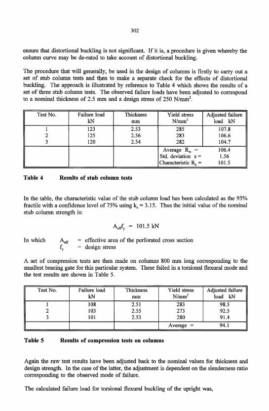
The procedure that will generally, be used in the design of columns is firstly to carry out a set of stub column tests and tilen to make a separate check for the effects of distortional buckling. The approach is illustrated by reference to Table 4 which shows the results of a set of three stub column tests. The observed failure loads have been adjusted to correspond to a nominal thickness of 2.5 mm and a design stress of 250 N/mm2•
Test No. Failure load Thickness Yield stress Adjusted failure kN mm N/mm2 load kN
1 123 2.53 285 107.8 2 125 2.56 283 106.6 3 120 2.54 282 104.7
Average R", = 106.4 Std. deviation s = 1.56 Characteristic Rk = 101.5
Table 4 Results of stub column tests
In the table, the characteristic value of the stub column load has been calculated as the 95% fractile with a confidence level of 75% using ks = 3.15. Thus the initial value of the nominal stub column strength is:
In which effective area of the perforated cross section design stress
A set of compression tests are then made on columns 800 mm long corresponding to the smallest bracing gate for this particular system. These failed in a torsional flexural mode and the test results are shown in Table 5.
Test No. Failure load Thickness Yield stress Adjusted failure kN mm N/mm2 load kN
1 108 2.51 283 98.5 2 103 2.55 273 92.5 3 101 2.53 280 91.4
Average = 94.1
Table 5 Results of compression tests on columns
Again the raw test results have been adjusted back to the nominal values for thickness and design strength. In the case of the latter, the adjustment is dependent on the slenderness ratio corresponding to the observed mode of failure.
The calculated failure load for torsional flexural buckling of the upright was,
303
Nb,Rd = 97.6 kN
Which is greater than the average value obtained from the test series, indicating that distortional buckling may have a minor influence. Consequently, the characteristic value of the stub column load is modified so that the fmal value is,
Aefrfy = 101.5 x 94.1197.6 = 97.9 kN
This value is then used as the basis for the calculation of all design strengths for the upright in compression. As an example, using this reduced value of the stub column strength, the calculated value of the torsional flexural buckling load for the column whose test results are shown in Table 5 is 90.5 kN compared with the observed average value of 94.1 kN.
Semi-rigid joints
The design of a pallet rack or shelving system is usually dominated by consideration of the rather flexible clipped joints that are widely used in European practice. The performance of these connections has to be determined by test and consideration· is given to separate consideration of the initial looseness as well as the stiffness. Markazi et al [9] have given detailed consideration to a number of proprietary connection systems and discussed the parameters and configurations that give rise to efficient beam and connector designs. Godley [10] has discussed the influence of connector stiffness on beam design.
The European design code allows two alternative test procedures to be used. These are illustrated in Figures 2 and 3. For the cantilever test in Figure 2, the measurement of moment and rotation are given by:
where a d ~l ~2
M = aF
lever arm for the load F distance between the gauges C1 and C2
deflection measured by gauge C1
deflection measured by gauge C2
For the portal frame test shown in Figure 3, the average moment in each connector is given by:
where d ~
width of the face of the upright (~i + ~2)J2
and the rotation of the connector is:
304
e
flexural rigidity of the upright flexural rigidity of the beam
The calculation of the average moment in the connector and its rotation assumes that all of the components except the connector itself behave in a linear elastic fashion.
The design moment for the cOlmection, MRd, is derived from the characteristic moment Mk by the relationship:
where YM is the partial safety factor for connections.
MRd may take any value below the maximum allowed in order to optimise the stiffness of the connection when a bilinear characteristic is adopted in the design.
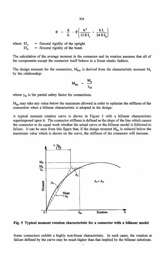
A typical moment rotation curve is shown in Figure 5 with a bilinear characteristic superimposed upon it. The connector stiffness is defined as the slope of the line which causes the connector to do equal work whether the actual curve or the bilinear model is followed to failure. It can be seen from this figure that, if the design moment MRd is reduced below the maximum value which is shown on the curve, the stiffness of the connector will increase.
Rotation e
Fig. 5 Typical moment rotation characteristic for a connector with a bilinear model
Some connectors exhibit a highly non-linear characteristic. In such cases, the rotation at failure defined by the curve may be much higher than that implied by the bilinear substitute.
305
In order to avoid this situation, the rotation at failure assumed in the bilinear model may not be more than 15% less than that indicated by the test curve. The moment rotation curves for all the tests on a connector are analysed in this way and the average value of the stiffness is taken to be the design value.
Where the analysis method allows the use of a multi-linear model for the connector, the design moment for the connector is calculated in the same way. Then an average curve for the connector is calculated from all of the test results by plotting the mean value of the rotation at increasing values of the bending moment up to the design moment. The multilinear model is defined as series of secant lines drawn below the average moment rotation curve.
In the case of the cantilever test, looseness is measured separately. The effects of looseness may be taken into account either by increasing the frame imperfections by an additional sway component or by adding the looseness as a horizontal or near horizontal line at the origin of the moment rotation model. In the case of the portal frame test, any looseness cannot be separately identified. It is incorporated into the moment rotation curve measured in the test which may, as a result, be more irregular than that obtained from the cantilever test and exhibit a lower stiffness.
Use of cold-reduced steel
A number of European manufacturers cold reduce their coil material before cold-forming it into racking components. This, of course, has the effect of raising the yield stress and reducing the ductility. It is well-known that reduced ductility is of particular concern in connections and this may be expected to be particularly the case with the clipped connections discussed above. To this end, tests on both components and complete installations have been carried out which have compared the performance of components cold-rolled from conventional and cold-reduced coil. Some of this work has been reported by Davies and Cowen [11]. It was concluded that the cold-reducing process had no adverse effect on performance.
Comparison of the European (FEM) and American (RMI) codes
Even allowing for the fact that, for member design, the RMI specification merely appeals to the AISI code whereas the FEM specification quotes the relevant clauses of Eurocode 3; Part 1.3 in full, the FEM code is the more detailed and more prescriptive. The FEM code describes global analysis in some detail whereas, in RMI, AISI procedures are merely implied. FEM has more load cases and considerably more onerous testing requirements.
The RMI Specification includes comprehensive seismic clauses in section 2.7. These are still under preparation in the FEM code.
At this stage, a comparison of the economic outcomes of using the two codes is not possible. The RMI code uses higher factors of safety and certain of the imperfection forces are also higher. However, this may be offset by such considerations as the inclusion of placement loads, the more rigorous treatment of sway stability and the statistical treatment of test results in the FEM code. The only way to resolve this would be by benchmark comparisons between the two codes and the worked examples in the codes offer a clear opportunity in this respect.
306
However, this work has yet to be carried out.
The two codes are both compared in more detail in the following sections:
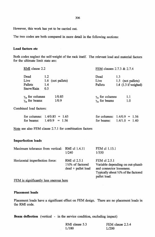
Load factors etc
Both codes neglect the self-weight of the rack itself. The relevant load and material factors for the ultimate limit state are:
RMI clause 2.2
Dead l.2 Live Pallets Snow/Rain
l.6 (not pallets) 1.4 0.5
Ym for columns Ym for beams
Combined load factors:
110.85 1/0.9
for columns: l.4/0.85 1.65 l.56 for beams: l.4/0.9
Note see also FEM clause 2.7.1 for combination factors
Imperfection loads
Maximum tolerance from vertical: RMI cl 1.4.11 1/240
Horizontal imperfection force: RMI cl2.5.1 1 Y2% of factored dead + pallet load
FEM is significantly less onerous here
Placement loads
FEM clauses 2.7.3 & 2.7.4
1.3 Dead Live Pallets
1.5 (not pallets) 1.4 (1.3 ifweighed)
Ym for columns Ym for beams
for columns: l.4/0.9 for beams: 1.411.0
FEM cl 1.13.1 1/350
FEM cl2.5.l
1.1 1.0
l.56 1.40
Variable depending on out-plumb and connector looseness. Typically about Y2% of the factored pallet load.
Placement loads have a significant effect on FEM design. There are no placement loads in the RMI code.
Beam deflection (vertical - in the service condition, excluding impact)
RMI clause 5.3 Ll180
FEM clause 2.3.4 Ll200
307
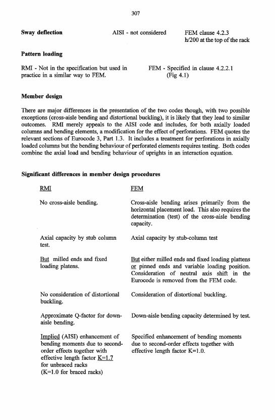
Sway deflection AISI - not considered FEM clause 4.2.3
Pattern loading
RMI - Not in the specification but used in practice in a similar way to FEM.
Member design
hl200 at the top of the rack
FEM - Specified in clause 4.2.2.1 (Fig 4.1)
There are major differences in the presentation of the two codes though, with two possible exceptions (cross-aisle bending and distortional buckling), it is likely that they lead to similar outcomes. RMI merely appeals to the AISI code and includes, for both axially loaded columns and bending elements, a modification for the effect of perforations. FEM quotes the relevant sections of Eurocode 3, Part 1.3. It includes a treatment for perforations in axially loaded columns but the bending behaviour of perforated elements requires testing. Both codes combine the axial load and bending behaviour of uprights in an interaction equation.
Significant differences in member design procedures
No cross-aisle bending.
Axial capacity by stnb column test.
But milled ends and fixed loading platens.
No consideration of distortional buckling.
Approximate Q-factor for downaisle bending.
Implied (AISI) enhancement of bending moments due to secondorder effects together with effective length factor K = 1. 7 for unbraced racks (K=1.0 for braced racks)
Cross-aisle bending arises primarily from the horizontal placement load. This also requires the determination (test) of the cross-aisle bending capacity.
Axial capacity by stnb-column test
But either milled ends and fixed loading plattens or pinned ends and variable loading position. Consideration of neutral axis shift in the Eurocode is removed from the FEM code.
Consideration of distortional buckling.
Down-aisle bending capacity determined by test.
Specified enhancement of bending moments due to second-order effects together with effective length factor K=1.0.
308
Global Analysis
In the RMI Specification, the global analysis requirements are implicit by appeal to AISI. In FEM, they are specific. Withsme exception, the end results should be similar. The exception arises from frame classification (clause 4.3.3.1) in FEM.
RMI allows "average" pallet loads for sidesway stability analysis.
Note The side-load requirements for global analysis are quite different between the two codes.
Moment-Rotation Characteristics
This is, of course, a crucial aspect of pallet rack design and there are significant differences between the two approaches.
Uses cantilever test for moment capacity and portal test (cl 9.4.2) for Mle relationship.
No separate consideration of "looseness"
Statistical interpretation optional and on a quite different basis to FEM.
Other aspects of testing
Uses cantilever test for both moment capacity and Mle relationship or alternatively the portal test for both.
Separate consideration of looseness which may be included in either the sway imperfection or in the Mle relationship.
Formal statistical interpretation of test results is required.
FEM includes the following mandatory tests which are not part of the RMI requirements:-
Connector looseness test clause 5.6
Shear test on beam end connector clause 5.7
Shear stiffness of upright franles clause 5.9
Bending test on upright sections clause 5.10
Bending test on beams clause 5.11 Note twist limitation
Tests on upright splices clause 5.15
The following test is included in FEM and may be of interest:
Floor connection.
309
Acknowledgements
The authors wish to acknowledge their long fruitful and enjoyable association with Section X of the Federation Europeenne de la Manutention (FEM) and the many discussions which have led to the new European design code and the technical content of this paper. They also wish to acknowledge the contributions of both FEM and the Rack Manufacturers Institute (RMI), especially Professor T Pekoz, to the code comparison work and for making the latest RMI code available at an early stage.
Conclusions
European harmonisation of design procedures for pallet racking has been a long process and has not been easy. However, it has been possible to harmonise long-held and disparate national procedures and traditions and the authors commend the resulting code as representing European-wide consensus of the current state-of-the-art.
A world code for the design of pallet racking is a realistic possibility. The authors hope that this paper may be a helpful step towards this end.
References
[1] Godley M H R. Storage racking. In Design of cold Formed Steel Members. Ed J Rhodes. Elsevier Applied Science. 1991. 361-399.
[2] Rack Manufacturers Institute. Specification for the design, testing and utilization of industrial steel storage racks. usA. 1997.
[3] American Iron and Steel Institute. Specification for the design of cold-formed steel structural members. 1996.
[4] European Committee for Standardisation (CEN). Eurocode 3: Design of Steel Structures. Part 1.3: General rules: Supplementary rules for cold formed thin gauge members and sheeting. ENV 1993-1-3. February 1996.
[5] Federation Europeenne de la Manutention: Section X. Recommendations for the design of steel static pallet racking and shelving. Final Draft for approval. February 1998.
[6] J M Davies. Down-aisle stability of rack structures. 11th International Speciality Conference on Cold-Formed Steel Design and Construction, St Louis, 20-21 October 1992, University of Missouri-Rolla, USA: 417-435.
[7] Rhodes J & Macdonald M. The effects of perforation length on the behaviour of perforated elements in compression. 13th International Speciality Conference on ColdFormed Steel Design and Construction, 8t Louis, 17-18 October 1996, University of MissouriRolla, USA, 91-101.
[18] Leach P and Taylor A. The behaviour of light gauge steel perforated sections subject to combined axial load plus bending. Bicentenary Conference on Thin-Walled Structures, University of Strathc1yde, Glasgow, 2-4 December 1996.

310
[9] Markazi F D, Beale R G and Godley M H R. Experimental analysis of semi-rigid boltless connectors. Thin-Walled Structures. Vol. 28. No. 1. 1997. 57-87.
[10] M H R Godley. Plastic design of pallet rack beams. Bicentenary Coriference on ThinWalled Structures, University of Strathc1yde, Glasgow, 2-4 December 1996.
[II] J M Davies, and J S Cowen. Pallet racking using cold-reduced steel. 12th International Speciality Conference on Cold-Formed Steel Design and Construction, St Louis, 18-19 October 1994, University of Missouri-Rolla, USA: 641-655.
[12] Pu et al (title not advised), 14th International Speciality Conference on Cold-Formed Steel Structures, St Louis, 15-16 October 1998, University of Missouri-Rolla, USA