A. DUGUE Airbus
109
14/11/2011 AUTO FLIGHT SYSTEM Part 1 Presented by A. DUGUE Airbus
Transcript of A. DUGUE Airbus

14/11/2011
AUTO FLIGHT SYSTEM
Part 1
Presented by
A. DUGUE
Airbus

Page 2
Table of Content
General
Architectures
o General principles
o Evolution
o Airbus architecture
AFS components
o Overview
o Interfaces HMI
o Modes, logics
o Protections / Warnings
Approach / Autoland
Airworthiness requirements

Page 3
Table of Content
General
Architectures
o General principles
o Evolution
o Airbus architecture
AFS components
o Overview
o Interfaces HMI
o Modes, logics
o Protections / Warnings
Approach/Autoland
Airworthiness requirements

Page 4
General Place of the AFS
Radio
communication
Autonomous
sensors
Radio
navigation
Traffic
management
FANS
Flight
management
FMS
Flight
guidance
AFS
Flight
control
FCS
Other
airplanes
Controller

Page 5
General Place of the AFS
The INNER LOOP (control)
• control of the aircraft around its center of gravity (same domain than FC)
• computation of surface order deflection
• limitation in range and speed of the orders coming from outer loop
The OUTER LOOP (guidance)
• control of the aircraft center of gravity along a trajectory (part of flight plan)
• computation of outer loop orders
• limitation in range and speed of the targets (FCU, FMS)
The Navigation LOOP (navigation)
• control the sequence of trajectories (flight plan)
• computation of targets to follow
Page 6
General Overall AFS description
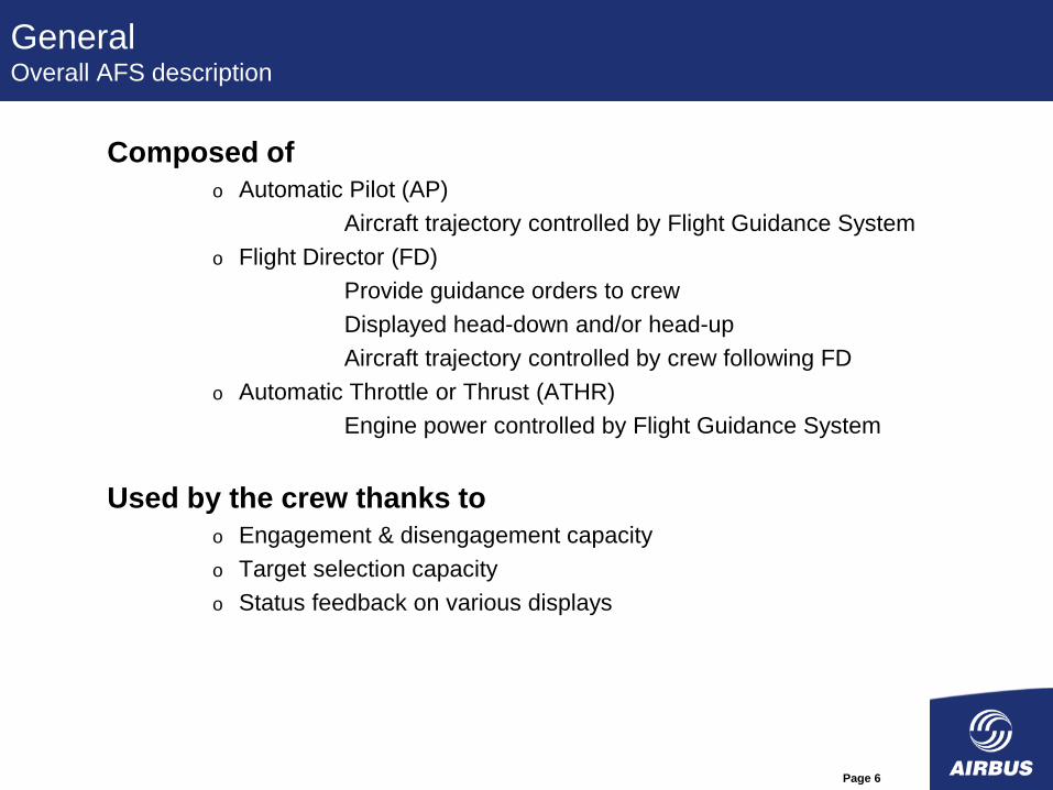
Composed of
o Automatic Pilot (AP)
Aircraft trajectory controlled by Flight Guidance System
o Flight Director (FD)
Provide guidance orders to crew
Displayed head-down and/or head-up
Aircraft trajectory controlled by crew following FD
o Automatic Throttle or Thrust (ATHR)
Engine power controlled by Flight Guidance System
Used by the crew thanks to
o Engagement & disengagement capacity
o Target selection capacity
o Status feedback on various displays

Page 7
General AFS objectives
PERFORMANCE
• Follow the targets
• Aircraft stability
• Robustness against disturbance
• Performance in autoland
COMFORT
• Handling qualities
• Behavior in turbulence
• Confidence of the crew towards AP behavior
SECURITY
• Behavior in case of disturbance
• Behavior in case of failures
• Availability of functions
• Optimize the fatigue of the actuators

Page 8
General AFS surfaces
Engines (energy control)
Ailerons (roll control)
Spoilers (roll and Vz control)
Rudder (yaw control)
Elevators (pitch control)
Trimmable Horizontal
Stabilizer (pitch control)
Nose wheel (ground steering)
Wheel brakes (landing)

Page 9
Table of Content
General
Architectures
o General principles
o Evolution
o Airbus architecture
AFS components
o Overview
o Interfaces HMI
o Modes, logics
o Protections / Warnings
Approach/Autoland
Airworthiness requirements

Page 10
Architecture General principles
Fail soft: to limit effect of a failure
o Limits Caravelle (cruise)
Fail passive: to passivate the first failure
o Duplex Boeing (2 AP)
o External monitoring Caravelle (autoland)
o Comparison (duplicated computation)
Consolidated points Concorde
Voters Airbus (1 AP)
Fail operational: to continue after the first failure
o Triplex Boeing (3 AP)
o Double monitored
Two active Airbus A300
Active/Stand-by Concorde and Airbus
(other than A300)

Page 11
Architecture General principles
MINOR
• low safety margins reduction
• low crew workload increase (flight plan change)
• passengers discomfort without injury
MAJOR
• significant reduction of safety margins
• reduction of crew ability to fulfill its task
• some injuries
HAZARDOUS
• large safety margins reduction
• crew workload increase so as the crew is not able to fulfill all tasks
• serious injuries or death of a limited number of passengers
CATASTROPHIC
• loss of the aircraft
• death of passengers
CATATROPHIC
HAZARDOUS
MAJOR
MINOR
EFFETS
PROBABILITy
PROBABLE LOW REMOTE EXTREMELLY
REMOTE
10-3
By flight
hour 10-5
10-9
10-7

Page 12
FCC 1
Architectures Boeing answer to “Fail passive” (777)
Inter channel
data bus Sensors
cruise : duplicate
land : triplicate
Displays
Actuators
FCC : Flight Control Computer (Separated FMS)
PFC : Primary Flight Computer
FCC 2
PFC PFC PFC C

Page 13
FCC 1
Architectures Boeing answer to “Fail operational” (777)
Inter channel
data bus
Sensors
cruise : duplicate
land : triplicate
Displays
Actuators
FCC 3
PFC PFC PFC C
FCC 2
Inter channel
data bus

Page 14
FCGU A
Architectures Airbus answer to “Fail passive” (A380)
Inter channel
data bus Sensors
Displays
Actuators
FCGU : Flight Control and Guidance Unit (Separated FMS)
PRIM : PRIMary flight comtrol computer
FCGU B
C
C
PRIM

Page 15
Architectures Airbus answer to “Fail operational” (A380)
Sensors Displays
Actuators
FCGU A
Inter channel
data bus
FCGU B
C
C
PRIM 1
FCGU A
Inter channel
data bus
FCGU B
C
C
PRIM 2

Page 16
Architecture Airbus principles – voter (3 entries)
time
Normal Failure
operation cases
Case A)
Case B)
Order
computation line 1
computation line 2
computation line 3
voter output

Page 17
Architecture Airbus principles – voter (2 entries)
time
Normal Failure
operation cases
Case A)
Case B)
Order
computation line 1
computation line 2
voter output

Page 18
Architecture Airbus principles – passivator (2 entries)
time
Normal Failure
operation cases
Case A)
Case B)
Order
computation line 1
computation line 2
voter output
+e
-e

Page 19
Table of Content
General
Architectures
o General principles
o Evolution
o Airbus architecture
AFS components
o Overview
o Interfaces HMI
o Modes, logics
o Protections / Warnings
Approach/Autoland
Airworthiness requirements

Page 20
Airbus AFS Architecture evolution Airbus AFS Architecture evolution
Number of
computers
for AFS
0
2
4
6
8
10
12
14
16
18
A300
1968
A310
1978
A320
1984
A340
1990
A380
2002
? N1 Limit
Auto THRT
TEST
COMP
PITCH
TRIM
YAW
DAMP
& LIM
LOGIC
COMP
LONGI
COMP
LAT
COMP
FCC
FMC
FAC
FLC
TCC
FMGC
FAC FMGEC
FMS
PRIM
Aircraft
Year

Page 21
Airbus AFS Architecture evolution Integration AP/FC - Architecture A310
NAVIGATION / DISPLAY
PFD
F M A Ertrtet
Ertert
Ertertttrrrrete
FCC - Auto Pilot
(outer and inner loops)
Control Surfaces
deflections
Auto Thrust
Manual
FADEC
FCU
AP actuators
FC actuators
FAC – Flight envelope
FMS - Option
TCC - Auto Throttle
MCDU
ENGINES
ND

Page 22
Airbus AFS Architecture evolution Integration AP/FC - Architecture A320
ELAC -
NAVIGATION / DISPLAY
PFD
F M A Ertrtet
Ertert
Ertertttrrrrete
Control Surfaces
deflections
Auto Thrust
Manual
FADEC
FCU
AP actuators
FC actuators
FMGC –
Autopilot (IL + OL)
Auto Thrust
Flight Management
MCDU
SIDE STICK
ENGINES
Auto Pilot
Manual
FAC – Flight envelope
ND
Manual Piloting
loops and
Protections

Page 23
Airbus AFS Architecture evolution Integration AP/FC - Architecture A330-A340
FCPC -
NAVIGATION / DISPLAY
PFD
F M A Ertrtet
Ertert
Ertertttrrrrete
Control Surfaces
deflections
Auto Thrust
Manual
FADEC
FCU
FC actuators
FMGEC –
Autopilot (IL + OL)
Auto Thrust
Flight envelope
Flight Management
MCDU
SIDE STICK
ENGINES
Auto Pilot
Manual
ND
Manual Piloting
loops and
Protections

Page 24
Airbus AFS Architecture evolution Integration AP/FC - Architecture A340-600
FCPC -
NAVIGATION / DISPLAY
PFD
F M A Ertrtet
Ertert
Ertertttrrrrete
Control Surfaces
deflections
Auto Thrust
Manual
FADEC
FCU
FC actuators
FMGEC –
Autopilot (OL only)
Auto Thrust
Flight envelope
Flight Management
MCDU
SIDE STICK
ENGINES
Auto Pilot
Manual
ND
Manual Piloting
loops and
Protections

Page 25
Airbus AFS Architecture evolution Integration AP/FC - Architecture A380-A350
FCGC -
NAVIGATION / DISPLAY
PFD
F M A Ertrtet
Ertert
Ertertttrrrrete
Control Surfaces
deflections
Auto Thrust
Manual
FADEC
FCU
FC actuators
MCDU
SIDE STICK
ENGINES
Auto Pilot
Manual
ND
Manual Piloting
loops and
Protections
FMS
Autopilot (IL only)
Auto Thrust
Flight envelope

Page 26
Table of Content
General
Architectures
o General principles
o Evolution
o Airbus architecture
AFS components
o Overview
o Interfaces HMI
o Modes, logics
o Protections / Warnings
Approach/Autoland
Airworthiness requirements

Page 27
Flight Control Computers
Flight Guidance Functions
Airbus AFS Architecture Detail of FCGC (A380 – A350)
FCGC 3
(Channel A +
Channel B)
DISPLAY
PFD
F M A
Control Surfaces
deflections
FADEC
FCU
SIDE STICK ND
FMS
FCGC 2
(Channel A +
Channel B)
FCGC 1
(Channel A +
Channel B)
SEC 3
(Channel A +
Channel B)
SEC 2
(Channel A +
Channel B)
SEC 1
(Channel A +
Channel B)
AFDX Network
Air Data
Inertial Data
Radio
Altimeter
…

Page 28
FMS
FCU
Guidance
control laws
“outer loop”
Guidance
target
engines Engine order
FD “inner
loop”
FD order
surfaces dsurface
Flight
control laws
“inner loop”
operational
logic
300
320
280
260
195
20
00
80
190
FL 290
0 1 2 35 34 .660 STD
10
20
10
10
20
10
THR CLB CLB ALT
NAV AP1 IFD2 A/THR
Modes
Inertial Data
Air Data
Su
rfa
ce
co
ntr
ol lo
op
Primary Flight Display
AP on
MMR
RA
FCGC
Airbus AFS Architecture Detail of FCGC (A380 – A350)

Page 29
Airbus AFS Architecture Detail of FCGC (A380 – A350)
FD CAP
Channel B
A/C actuators
AP / FD
OUTER LOOP 1
Channel A
SENSORS 1 AP 2 engaged
AP / FD
OUTER LOOP 2
FD FO SENSORS 3
CAP on 3
FO on 3
SENSORS 2
AP / FD
OUTER LOOP 1
SENSORS 1
AP / FD
OUTER LOOP 2
FD inner loop 1
FD inner loop 2
SENSORS 3
CAP on 3
FO on 3
SENSORS 2
INNER LOOPS
AP 2 engaged
INNER LOOPS
M M M M
M = Monitoring
FD inner loop 1
FD inner loop 2
M
M
M
M

Page 30
Table of Content
General
Architectures
o General principles
o Evolution
o Airbus architecture
AFS components
o Overview
o Interfaces HMI
o Modes, logics
o Protections / Warnings
Approach/Autoland
Airworthiness requirements

Page 31
AFS components Airbus Human Machine Interface
Three main interfaces
o Flight Control Unit (FCU)
AP, FD and ATHR engagement capability
Mode engagement and associated target selection
o Flight Management System (FMS)
Flight plan creation and modification
DIR TO capability
o Primary Flight Display (PFD)
For AP, FD and ATHR engagement status
Current modes in control “engaged modes”
Current target
Additional quick disconnection means
o On the side stick for AP
o On the throttles for ATHR

Page 32
AFS components
Airbus Human Machine Interface
Flight
Control
Unit (FCU)
(Display of
targets and
modes control)
side sticks
and ID P/B
(quick AP
disconnection)
KCCU and
MFD
(control of the AP in
managed mode)
THR levers
and ID P/B
(modes
engagement, ATHR
limitation, quick
ATHR
disconnection)
Primary
Flight Display
(FPD)
(Display of modes
and targets)
Pedals
(AP disconnection
on ground)

Page 33
AFS components Airbus Human Machine Interface

Page 34
AFS components Airbus Human Machine Interface – FCU (A330/A340)
Speed / Mach Heading / Track Altitude Vertical Speed / Flight Path Angle
Mode engagement & target selection capability
AP engagement
ATHR engagement
Approach arming LOC only approach arming
Current altitude acquisition & hold
Automatism engagement
Specific engagement & arming

Page 35
AFS components Airbus Human Machine Interface – FCU (A380)
Increase dissimilarity
Only 1 FD P/B
No more
« push to
level off »

Page 36
AFS components Boeing Human Machine Interface – MCP
MCP 777 (Mode Control Panel)
MCP 787 (Mode Control Panel)

Page 37
AFS components Airbus Human Machine Interface - PFD
Flight
Director
Thrust Vertical Lateral Approach
capability
AP, FD and ATHR
engagement status
Guidance modes AFS status
Flight
Modes
Annonciator
(FMA)
AFS
targets

Page 38
AFS components PFD – ND Boeing (777)

Page 39
AFS components
Coherence MCP – PFD (Boeing)

Page 40
AFS components Coherence MCP – PFD (Airbus)

Page 41
AFS components FCU Back-up (A380)
Main benefit :
o Increase FCU availability -> FGE availability

Page 42
AFS components HUD (A380)
Main benefit :
o Ease for head up - head down
transitions
o Reduction of minimas for take-off
(RVR)
o Reduction of minima in approach
o Possibility to perform CAT 2
operation on CAT 1 runways

Page 43
AFS components HUD (A380)
Flight Director
Horizon line
Flight Path
Vector
Copy of FMA

Page 44
AFS components FMS
Specific key
to request
managed
mode

Page 45
AFS components
AP description
The Auto pilot (AP) acts on the surfaces and on the nose wheel in
order to : • maintain targets selected by the pilot (heading, track, vertical speed,
altitude, …),
• follow a flight plan generated by the FMS (climb, cruise, descent and
approach),
• perform an automatic landing (including roll out on ground),
• perform a Go Around.
The AP can’t be engaged on ground for take-off roll
(engagement only possible 5 sec. after aircraft lift off).
The AP can or can not be coupled with the Autothrust (ATHR).

Page 46
AFS components
AP description
AP engagement
- Engagement possible 5 sec after the aircraft lift off by action on one of the AP
push-button of the FCU.
- Only one AP can be engaged at once, except in ILS approach/autoland and go
around.
- When both AP are engaged, AP 2 is in stand-by.
- When the AP is engaged, the side-sticks and pedals are locked.

Page 47
AFS components
AP description
AP disengagement
Pilot disconnection:
• action on Instinctive Disconnect button on side-stick
(voluntary disconnection)
• action on AP FCU push-button
• action on the side-sticks
• action on pedals (only on ground on A340)
Entry into protection: • VMO, MMO
• angle of attack
• excess roll ( | | > 45°)
• excess pitch ( > 25° or <-13°)
Failures: • loss of surface
• loss of sensors
• loss of FCU
• …

Page 48
AFS components
AP description
Transition between Manual piloting and Automatic control
Manual AP
Neutral side stick: the AP order is immediately taken into account.
Deflected side-stick: the AP engages but is not active as long as the side-stick is
deflected. The pilot has 4,5 sec to release the side-stick before AP
disengagement.
In both cases, when the AP becomes active, the AP order is first synchronized on
the manual order in order to avoid surface jerk.
Deflected pedals: the AP order is immediately taken into account.
(A340) except if the side-stick is deflected. The pilot has 4,5 sec to release the
pedals before AP disengagement.
AP Manual At AP disengagement, synchronization of the manual order on the AP order.

Page 49
AFS components
FD description
The Flight Director (FD) provides guidance information, displayed
on the PFD, in order to allow, in manual control: • maintain targets selected by the pilot (heading, track, vertical speed,
altitude, …),
• follow a flight plan generated by the FMS (climb, cruise, descent and
approach),
• perform an automatic landing (including roll out on ground),
• perform a Go Around.
The FD can be engaged on ground for take-off roll.
The FD can or can not be coupled with the Autothrust (ATHR).

Page 50
AFS components
FD representation 1 (cross bars)
Side stick forward + left

Page 51
AFS components
FD representation 2 (FPD)
Side stick forward + right

Page 52
AFS components
FD representation 3 (V bars)
Side stick back + right

Page 53
AFS components
ATHR description
The Auto Thrust (ATHR) acts on the engines (FADEC) in order to: • maintain a thrust,
• track a speed or a Mach.
The ATHR can be engaged on ground for take-off.
The ATHR works always with the same sensors side than the AP.
The ATHR can be “killed” for the whole flight by a long action (15
sec) on Instinctive Disconnect push-button on thrust levers.

Page 54
AFS components
ATHR description
ATHR engagement - Manual engagement by action on the ATHR push-button of the FCU.
- Automatic engagement on ground or in Go around when the thrust levers are set on
TOGA (max thrust).
- Automatic engagement in case of Alpha Floor.
- The ATHR order is max limited by the position of the levers.
Once engaged, the ATHR is active (ie it really commands the engines) only if the
levers are set between Idle and CLB detent.
When the ATHR is engaged and active, the operational lever
position is on CLB detent (or MCT in case of engine out).
TO/GA
CLB
MCT FLEX/TO
IDLE

Page 55
AFS components
ATHR description
ATHR disengagement - Action on Instinctive Disconnect button on thrust levers,
- Action on ATHR FCU push-button,
- Reduce all levers on Idle,
- Failure cases (sensors, engines, …).
At ATHR disengagement by ID button, the engine thrust goes immediately to the
thrust corresponding to the levers position.
Else, the thrust is frozen to current value until the pilot moves the thrust levers.

Page 56
AFS components Modes, Operational logic and Control laws
Once an automatism is engaged (AP or FD or ATHR), the Flight Guidance System controls the aircraft (or provides information).
The crew can chose: o To impose the guidance reference
use of FCU selectors to set SPEED/MACH, HDG/TRACK, ALT, V/S/FPA
short term action
Airbus “selected modes”
Pull action on selector to engage the modes
o To give the hand to the FMS which will give the guidance reference (lateral and longitudinal flight plan, speed or Mach),
flight plan input & modification in the FMS
long term action
Airbus “managed modes”
Push action on selector to engage the modes
Each mode: o provides control for the aircraft in a specific manner by activating a corresponding
control law.
o has specific conditions of engagement (operational logic)

Page 57
AFS components Modes, Operational logic and Control laws
Pull: “the pilot takes over” => “selected mode”
Push: “the pilot let the system” => “managed mode”

Page 58
AFS components Modes, Operational logic and Control laws
Lateral axis modes
Name Runway heading track
Display RWY TRK HDG TRK NAV APP NAV FINAL APP
Control law TRK HDG TRK
Type selected selected selected managed managed managed
navigation
HDG or TRK or HPATH
Name Go Around localizer capture localizer track Roll out
Display GA TRK (F-) LOC* (F-) LOC LAND FLARE ROLL OUT
Control law TRK LOC and ALIGN roll out
Type selected
LOC
LS approach and landing
landing

Page 59
AFS components Modes, Operational logic and Control laws
Lateral control law brief description
HDG acquisition and hold of a heading (true or magnetic) value
TRK acquisition and hold of a track (true or magnetic) value
Bank acquisition and hold of a bank angle value
HPATH acquisition and hold of a lateral profile
LOC acquisition and hold of a localizer beam
ALIGN aircraft alignment with runway axis (crosswind conditions)
roll out acquisition and hold of runway axis following automatic landing

Page 60
Objectives
The aim of the HDG control law is to capture and then hold the heading target.
Principles
Roll Order (deg)
Gain
HDG tgt
(deg)
HDG
(deg)
LIM
AP dynamic
roll order
limitation
DY
(deg)
com Gain
Turn continuity
function:
• target changes
•HDG/TRK
switching
|DY|
|com|
AFS components Heading Control Law

Page 61
AFS components Modes, Operational logic and Control laws
165
TURN
to select a
heading
PULL
to engage
the HDG
mode
Capture and hold of a heading
165

Page 62
AFS components Modes, Operational logic and Control laws
Vertical
axis
modes
Name open descent open climb vertical speed flight path angle
Display OP DES OP CLB V/S FPA
Control law SPD/MACH SPD/MACH V/S FPA
Type selected selected selected selected
Name altitude acquisition altitude hold climb
Display ALT* ALT DES FINAL DES CLB
Control law ALT star ALT SPD/MACH
Type selected or managed selected or managed managed managed managed
descent
VPATH or SPD/MACH or V/S
Name glide capture glide trackspeed reference
system
Display (F-) G/S* (F-) G/S LAND FLARE SRS
Control law flare nose down SRS
Type selected
landing
Glide
LS approach

Page 63
AFS components Modes, Operational logic and Control laws
Longitudinal control law brief description
SPD/MACH Speed hold during level change with VLS and VMO protections, combined with A/THR THR mode
V/S acquisition and hold of a vertical speed value with VLS and VMO protections
FPA acquisition and hold of a flight path angle value with VLS and VMO protections
ALT hold of an altitude value
ALT star acquisition of an altitude value
VPATH acquisition and hold of a vertical profile
SRS speed hold for T/O or G/A with protection against excessive pitch angle and ensuring a minimum vertical speed
Glide acquisition and hold of a glide slope
Flare aircraft rotation to ensure touchdown performances (autoland)
Nose down aircraft derotation following touchdown (autoland)

Page 64
Altitude Hold control law
Objectives
The aim of the ALT control law is to hold the altitude target
Principles
+
-
Longitudinal
Law (Nzc)
Target
Altitude
Measured
Altitude Flight Director
+
-
Vertical
Speed
Gain Lim
Gain

Page 65
AFS components Glide Control Law
Glide characteristics
runway
horizontal
glide slope
theoretical slope 3° +/-0.15°
height at runway
threshold : 55ft +/-10ft
Positive
deviation
A340
max slope +/-0.8°
DZILS V
Vertical speed
V/S
VGND

Page 66
AFS components Glide Control Law
Objectives
The aim of the Glide control law is to capture and then track the ILS glide
slope.
Principles
The two main functions are :
o estimation of Z and VZ deviation
o guidance control law
ADIRS
(Air Data &
Inertial Ref.)
Glide
deviation
processing
VZ deviation
estimation
ILS Z deviation
estimation
Glide capture &
glide track
activation logic
GLIDE
GUIDANCE
LAW
Nz order to FD
Nz order
Activation
DVZ
DZ
Deviations Estimation

Page 67
Glide control law
Guidance law
Nz Order
(g)
DZILS
DV/S
Nz Order
to FD
Gain Kz Lim
F/D
Gain +
+
+
+
+
q Gain
dV/dt Gain

Page 68
AFS components Modes, Operational logic and Control laws
TURN
to select
a VS
PULL
to engage the
VS mode
+2000
13000 ft
+2000
Capture and hold of a vertical speed

Page 69
AFS components Modes, Operational logic and Control laws
Particular cases of TO and GA
TO and GA modes are engaged by pushing
the thrust levers on TOGA detent.
Longitudinal axis mode: • SRS mode: speed capture and hold: V2+10 at take-off, current aircraft
speed in go around
Lateral axis mode: • RWY: follow LOC axis at take-off (with FD only)
• GA TRACK: current aircraft track hold in go around
CLB
MCT FLEX/TO
TO/GA

Page 70
AFS components Modes, Operational logic and Control laws
Particular case of Approach
The approach modes are engaged thanks to specific push-buttons on the
FCU.
LOC To engage only lateral
approach modes
APPR To engage lateral and
longitudinal approach modes
No longitudinal approach mode without lateral approach mode

Page 71
AFS components Modes, Operational logic and Control laws
Coupling AP/FD/ATHR with FM
Purpose: to follow a flight plan generated by the
FM (climb, cruise, descent, approach) with
AP/FD engaged.
The flight plan (lateral et longitudinal) and its
parameters (speed, level off, cruise altitude, …)
is entered in the MCDU on ground (can be
modified in flight).
Once the managed modes engaged, the FM sends to the FGS outer loops orders: • c (commanded roll angle) or HDG/TRK (depending on submode),
for lateral guidance • Dc (commanded pitch difference) or speed/VS/FPA (depending on
submode) for vertical guidance • Speed target or thrust target.
Different sharing on A400M

Page 72
AFS components Modes, Operational logic and Control laws
Mode arming
Some modes are armed before being engaged :
• Lateral: RWY, NAV, LOC (F-LOC)
• Vertical: ALT, CLB, DES, GS (F-GS)

Page 73
AFS components Mode equivalence Boeing / Airbus
Lateral modes Longitudinal modes

Page 74
AFS components ATHR modes
ATHR modes • When engaged with neither AP nor FD, the ATHR works in
SPEED/MACH.
• When at least one AP or FD is engaged, the ATHR mode active
depend on the longitudinal AP/FD active mode.
Basic principle: to not let a same objective be controlled by 2
commands (risk of conflict or instability).
For example:
• AP/FD mode: OPEN CLB ATHR mode: THRUST (speed
hold by the elevators)
• AP/FD mode: V/S ATHR mode: SPEED (speed hold by the
engines)

Page 75
AFS components Modes, Operational logic and Control laws
ATHR modes
ATHR control law brief description
SPEED/MACH acquisition and hold of a speed/Mach value
THRUST acquisition and hold of a thrust value (idle or thrust limit), combined with SPD/MACH or SRS
Name Thrust Speed Mach
Display THR XXX SPD MACH
Control law thrust
Type selected or managed selected or managed selected or managed
A/THR SPEED/MACH

Page 76
Auto THRust control loop
Objectives
The aim of the A/THR outer loop is to compute thrust variation and pitch
control orders , in order to :
• control the A/C speed/mach according to Target
• While keeping coordination with AP longitudinal control (slope) and
compensating engine pitching moment

Page 77
Principles: pitch & thrust control for A/THR
+
-
Target
Speed
Actual
Speed
+
-
dV/dt
Acceleration
target Gain
DVc
Gain pitch order
+
+
LIM Gain
d/d
t
Auto THRust control loop
onAccelerati
Thrust
Engine
Characteristics
Engine order
+
-
Target
Speed
Actual
Speed
+
-
dV/dt
Gain
DVc
+
+
LIM Gain
d/d
t

Page 78
AFS components ATHR modes
The ATHR is able to manage Engine failures :

Page 79
AFS components ATHR modes
The ATHR is able to manage Engine failures :

Page 80
AFS components Protections
AP speed protections
Purpose: to avoid speed excursion outside AP/FD operational envelope:
VLS - VMAX (VMO, VFE, VLE).
Protected AP/FD modes: V/S, FPA, CLIMB, DESCENT, OPEN CLIMB,
OPEN DESCENT, ALTITUDE ACQUIRE, SRS.
The objectives of the protections are to maintain: • in climb, at least VLS + 5 (or VLS if the initial speed target was near VLS)
• in descent, at the most VMO (ou VLE) in full conf or VFE + 4 slat extended
Not protected modes: ALTITUDE, G/S CAPT or G/S TRACK, FINAL DES
Priority is given to the trajectory

Page 81
AFS components Protections
ATHR protection “Alpha Floor”
Purpose: to avoid stalling in case of aircraft
low energy.
Upon angle of attack condition: • the ATHR automatically engages in Alpha
Floor mode,
• Full thrust is commanded to the FADEC.
Exit of Alpha Floor mode by ATHR
disengagement.
Management of engine failures

Page 82
AFS components AP authority (long)
AP authority (longitudinal axis)
The maximum longitudinal authority of the AP (=maximum load factor that the
AP can order) depends on the longitudinal active mode:
• 0,3 g in SRS (TO and GA), G/S CAPT, G/S TRACK,
• 0,05 g in clean/0,1 g in hyper in ALT, V/S, FPA
• 0,1 g in ALT ACQ, OPEN
• 0,15 g in level off
• authority increased to 0,15 g when :
- airbrakes extension
- slope reversion
- transition VMO/MMO
In speed protection, the authority if increased to 0,3 g.

Page 83
AFS components AP authority (lat)
AP authority (lateral axis)
The maximum lateral authority of the AP (jmax commanded) depends on
the lateral active mode:
• 30° in LOC CAPT
• 10° in LOC TRACK below 700 ft
• between 15° and 30° (depending on the Mach) in NAV, TRK, HDG
30
15
Mach 0,57 0,75
In HDG, TRK
30
15
Vcar-Vc 3 10
Limitation in case of EO jmax jmax

Page 84
AFS components Warnings
Warnings AP OFF warning:
• message on EWD: AP OFF
• sound: CAVALRY CHARGE
• light: MASTER WARNING
ATHR OFF warning:
• message on EWD: A/THR OFF
• sound: GONG
• light: MASTER CAUTION
• THR LK on FMA (frozen thrust)
ENGx A/THR OFF
• sound: Single Chime
• light: MASTER CAUTION
• THR lever x: Man adjust
ATHR Limited
• sound: single chime
• light: MASTER CAUTION
• THR CLB flashing on FMA
Triple click
• FMA change not commanded (landing cat or mode)
MASTER
WARN
MASTER
CAUT

Page 85
AFS components Warnings
Warnings Altitude Alert
• sound: C. CHORD
• flashing Altitude window on PFD
Excess dev warning
• blinking of LOC and GLIDE scales on PFD
Autoland warning
• AUTOLAND light below 200 ft if
• excess dev warning
• both AP disengagement
• RA difference 15 ft (2 RA only)

Page 86
AFS components Flight Envelope computation
VMO/MMO (Max Op. Speed)
VLS (Lowest Selectable Speed)
Va prot (neutral stick)
Va max (full back stick) a floor

Page 87
AFS components Main interfaces
Main interfaced systems with AFS
• ADIRS = ADR CAS, Mach, TAS, AOA, SS, Zp, TAT, ...
+ IRS Nx, Ny, Nz, p, q, r, hdg, trk, Vgnd, Zbi, Vzbi, ...
• Multi Mode Receiver (MMR) deviation VS xLS axis
• Radio Altimeter (RA) height below the aircraft
• Fuel Quantity and Mesurment System (FQMS) weight and CG
• Slat and Flap Control Computer (SFCC) aircraft configuration
• Landing Gear Extraction and Retraction System (LGERS) LG
position

Page 88
Table of Content
General
Architectures
o General principles
o Evolution
o Airbus architecture
AFS components
o Overview
o Interfaces HMI
o Modes, logics
o Protections / Warnings
Approach/Autoland
Airworthiness requirements

Page 89
Approach / Autoland
Approach type
2 different approach types:
Precision approach:
The guidance is performed on a ILS or MLS beam or GLS signal.
Under particular conditions, it can lead the aircraft to autoland with
automatic roll out.
Non precision approach:
The guidance is performed on a theoretical profile computed by the
FM until the MDA/MDH (Minimum Descent Altitude/Height), height at
which the pilot must take over to finish manually the landing (selected
modes/FM modes/FLS approach).

Page 90
Approach / Autoland
Ground station
DGPS
Localizer
Glide
3°
ILS / MLS
GLS (GPS / DGPS)

Page 91
Approach / Autoland
Approach selection
1L
2L
3L
4L
5L
6L
1R
2R
3R
4R
6R
5R
5
1
01
5
2
0
A R R I V A L T O L F B O
A P P R V I A S T A R
V OR 3 3 L - - - - - - - - - - - -
T R A N S
- - - - - -
A P P R A V A I L A B L E
ML S 3 3 L 3 5 0 0 M
3 2 7 M T B N / 5 1 0
IL S 3 3 L 3 5 0 0 M
3 2 7 T B N / 1 0 9 . 3 0
VO R 3 3 L 3 5 0 0 M
3 2 7
ER A S E I N S E R T * FP

Page 92
Approach / Autoland General principles
Autoland
o Capability to perform an approach and to land an aircraft in Instrument
Meteorological Conditions (IMC)
Requires 3 elements
o A crew qualified for this specific operation
Role of the airline and its local authority
o An airfield configured for this specific operation
Role of the airport
o An aircraft certified for this specific operation
Role of the aircraft manufacturer
Detailed herefater

Page 93
Approach / Autoland Operation description
Localizer
Glide
3°
LOC capture LOC track Decrab Roll out
ALT GS* GS Flare Nose down
Speed select Speed hold Retard
Lat.
Vert.
Thrust
Mode sequence realized automatically by the FGS

Page 94
Approach / Autoland Operation description
17° min cockpit
viewing angle
550m RVR
Cat I
200 ft DH
Adaptation from FAA Source
3° Glide Slope
Glide Slope
Antenna
300m from
threshold
Threshold 700m from
threshold
Lights
350m RVR 100 ft DH
Cat II
50 ft DH
200m RVR
Cat IIIa
• Scaled illustration

Page 95
Approach / Autoland Operation description

Page 96
Approach / Autoland Approach Categories
Category I
o Conditions
Decision height (DH) down to 200ft
Runway Visual Range of 800m
o Regulations
No specific ones in Europe, CS 25.1329
AC 120-29A in the US
Category II
o Conditions
Decision height between 100ft and 200ft
Runway Visual Range of 300m
o Regulations
CS AWO subpart 2 in Europe
AC 120-29A in the US

Page 97
Approach / Autoland
Approach Categories
Category IIIA
o Conditions
Decision height between 50ft and 100ft
Runway Visual Range of 200m
o Regulations
CS AWO subpart 3 (and 1 if automatic landing) in Europe
AC 120-28D in the US
Category IIIB
o Conditions
Decision height below 50ft or no DH
Runway Visual Range of 75m
o Regulations
CS AWO subparts 1 & 3 in Europe
AC 120-28D in the US

Page 98
Approach / Autoland Detailed regulation
Constraints on the system architecture
o Depending on the capability to be achieved
Fail passive / fail operational (+ fail-passive after 1st failure)
o Imposed failure rate for approach abortion
5% of go around rate
o Imposed AP loss failure rate
o Imposed minimum installed equipments
o Application of 25.1309
o Developments standards for ILS/MLS receivers
Constraints on the interface with the crew
o Excessive deviations
Required from a given height
Proposed thresholds

Page 99
Approach / Autoland Detailed regulation
Constraints on the performance of the Guidance o Demonstrated in two cases
Mean risk (all elements according to their occurrence)
Limit risk (all elements according to their occurrence, except one at its most stringent value)
o Evaluation of the following parameters
X and Y at touch-down
Vertical speed at impact
Bank angle
Lateral velocity or side slip angle
o Thresholds and acceptable probability
Defined (range from 10-5 to 10-8)
Link to mean/limit risk
Wide range of requirements … o Very specific and critical operation

Page 100
Table of Content
General
Architectures
o General principles
o Evolution
o Airbus architecture
AFS components
o Overview
o Interfaces HMI
o Modes, logics
o Protections / Warnings
Approach/Autoland
Airworthiness requirements

Page 101
Airworthiness General requirements
Today requirements for Large Airplanes o Similar regulation in Europe and in the US
o Harmonisation still on-going
• For general rules and cruise FGS:
o CS 25 replacing JAR 25 for EU states
o FAR 25 in the US
• For autoland:
o JAR AWO (All Weather Operations) Part 1 for automatic landing
o JAR AWO Part 2 and 3 for precision approaches and autoland in reduced visibility conditions.
General requirements examples o Applicable to AFS
o System level
25.1301 for “design appropriate to its intended function”
25.1309 for safety criteria (drives the architecture)
25.1322 for warnings and cautions
25.1329 for FGS systems
o Equipment level
25.1431 for hardware qualification

Page 102
Airworthiness Specific requirements
25.1329 Automatic pilot system & 1335 Flight director

Page 103
Airworthiness Specific requirements
Specific requirements for ILS approach Depending on the Decision Height, the regulation imposes to have :
• 50 ft < DH < 100 ft : autoland fail passive, automatic thrust control; automatic Go Around
• DH < 50 ft : autoland fail operative, automatic thrust control, fail passive automatic Go Around, automatic rollout
• no DH : autoland fail operative, automatic thrust control, fail passive automatic Go Around, fail passive automatic rollout, anti-skid braking
And requirements on the number of equipment : ILS, RA, PFD, FWS, …
Autoland fail passive: An autoland is fail passive if, in the event of a failure, there is no significant out-of-trim
condition or deviation of flight path or attitude but the landing is not completed automatically.
i.e. “Loss of the function, but safety ensured”
Autoland fail operative: An autoland is fail operative if, in the event of a failure, the approach, flare and landing
can be completed by the remaining part of the automatic system. i.e. “No function loss, performance and safety ensured”

Page 104
Airworthiness Flight tests for autoland
Autoland
100 autolands in various conditions
• weight / CG
• wind: head, cross, back
• runways: at least 3 different runways (altitude runways depending on
certification)
Go around 10 go around
• at various height
• with engine failure (established or at go around)
Roll out 20 roll out in autoland conditions (thrust dissymetry)
All of the above complemented with Simulation results (Monte-Carlo), whose
statistics have to pass AWO Criteria.

Page 105
Airworthiness Documentation
The required conditions to allow CAT III are defined in the Aircraft Flight Manual
(AFM) which is document approved by airworthiness authorities.
For the autoland, it contains:
• The limitations use
- wind limits (head, cross, back)
- values of DH, RVR
• The required equipments
- list of airctaft systems depending on the operational category
• The procedures
- normal procedures to be applied during the autoland
- procedures to be applied in case of failure
This document is used by the companies to write the Flight Crew Operating
Manual (FCOM) which is used by the crew.
Procedures and rules of the FCOM can be more conservative than whose approved
in the AFM.

Page 106
Airworthiness International standards
Compliance is also shown
o By application of international standards
o Not specific to Airbus
Some examples
o Software development
ED 12B or DO 178B
o Hardware development
ED 14D or DO 160D
o Complex components development
ED 80 or DO 254
o Certification considerations for highly integrated or complex aircraft
systems
ED 79 or ARP 4754

Page 107
Airworthiness Additional documents
CRI : Certification Review Item (JAA/EASA)
Discussed and agreed between authorities and Airbus
Some examples
o CRI B-10
Human factors evaluation of flight deck and novel design
o CRI F-22
Software formalised requirements validation and verification
o …

Page 108
Hardware & Software
System bench
Integration simulator
Aircraft flight
Pre-code
Equipment + SAO
specification
System specification
Aircraft Specification
Desk simulator
Airworthiness Validation and Verification

Page 109
© AIRBUS Operations S.A.S. All rights reserved. Confidential and proprietary document. This document and all information contained herein is the sole property of AIRBUS Operations S.A.S. No intellectual property
rights are granted by the delivery of this document or the disclosure of its content. This document shall not be reproduced or disclosed to a third party without the express written consent of AIRBUS Operations S.A.S. This
document and its content shall not be used for any purpose other than that for which it is supplied. The statements made herein do not constitute an offer. They are based on the mentioned assumptions and are expressed
in good faith. Where the supporting grounds for these statements are not shown, AIRBUS Operations S.A.S. will be pleased to explain the basis thereof.
AIRBUS, its logo, A300, A310, A318, A319, A320, A321, A330, A340, A350, A380, A400M are registered trademarks.