
A Dual Second-Order SOGI based Control Algorithm for UPQC ... · UPQC is utilized for mitigation of...
8
International Journal of Applied Engineering Research ISSN 0973-4562 Volume 12, Number 10 (2017) pp. 2489-2496 © Research India Publications. http://www.ripublication.com 2489 A Dual Second-Order SOGI based Control Algorithm for UPQC under Distorted Grid and Load Conditions Hareeshkumar Yada 1 Research Scholar, Department of Electrical Engineering, JNTU, Hyderabad, Telangana, India. 1 ORCID: 0000-0002-4254-6808 Dr.M.S.R Murthy 2 Professor, Department of Electrical Engineering, CMRCET, Hyderabad, Telangana, India. Raju Chintakindi 3 Asst.Prof, Department of EEE, Vaagdevi College of Engineering, Warangal, Telangana, India. Abstract This paper presents a Second-Order Second Order Generalized Integrator (SO-SOGI) based control algorithm for UPQC (Unified Power Quality Conditioner), an integration of DVR and DSTATCOM. This paper mainly aims to mitigate source voltage and load current harmonics, unbalance and power factor improvement. In this paper, SO-SOGI-PLL (Phase-Locked Loop) is employed for UPQC to generate reference voltage and current signals for enhancing power quality at the utility mains. SO-SOGI based PLL is utilized for power quality enhancement because of its dynamic response, better harmonic and inter harmonic compensation, tracking accuracy and faster detection of reference signal under all varying load and grid conditions. The proposed three-phase UPQC is utilized for mitigation of voltage harmonics, current harmonics, sag and swell with a simple control technique. The control algorithm is tested and evaluated using MATLAB/Simulink. Keywords: Power Quality (PQ), Phase - Locked Loop (PLL), Second-Order Second Order Generalized Integrator (SO- SOGI), and Unified Power Quality Conditioner (UPQC). INTRODUCTION Non-linear loads are increasing widely and causing most severe problems at the point of common coupling (PCC). Today’s day of interest is towards renewable energy sources for production of electricity. In this regard, single-phase and three-phase photovoltaic (PV) power generation is increasing widely for residential and commercial applications. In order to integrate these PV systems, Grid connected converters are utilized. But, these are creating severe power quality (PQ) issues at the grid system like harmonic generation, source unbalancing and power factor deterioration. Similarly, non- linear loads such as rectifiers, arc furnaces and fluorescent lamps etc are causing current related problems such as harmonics, unbalance and excessive reactive power demand etc. [1-4]. 92% of interruptions are due to voltage sags and to be compensated within 3 cycles. Voltage swells are less frequent; but, these swells are producing electromagnetic stress in power transformers due to flux saturation [5]. Nearly 48% of power quality problems are due to voltage sags/swells and 22% are due to harmonics [6]. Any problem in voltage / current will lead to the malfunctioning of customer loads and may damage sensitive loads in terms of power quality [7]. Custom power devices (CPD’s) such as DVR (Dynamic Voltage Restorer), DSTATCOM (Distribution Synchronous Compensator and UPQC (Unified PQ Conditioner) are more superior to passive filters and provide best solution for power quality issues. A UPQC is a combination of DVR and DSTATCOM and provides single solution for both voltage and current related problems with a common DC link capacitor at the DC bus. An attempt to improve the performance of UPQC is made by introducing SO-SOGI based QSG and PLL for estimation and extraction of fundamental voltage and current signals under distorted grid and load conditions. Different UPQC topologies are explained in the literature such as Instantaneous PQ theory [8], Synchronous Reference Frame (SRF) theory [9], In [10], three control algorithms such as UVT (Unit Voltage Template), DQ Theory and theory based on Fourier analysis are compared for single-phase applications. The performance of UPQC depends on the tracking accuracy of voltage and current, speed and control method that was employed. Keeping accuracy and reliability in view, many PLL techniques are proposed in literature such as SRF-PLL,
-
Upload
trinhkhuong -
Category
Documents
-
view
217 -
download
1
Transcript of A Dual Second-Order SOGI based Control Algorithm for UPQC ... · UPQC is utilized for mitigation of...

International Journal of Applied Engineering Research ISSN 0973-4562 Volume 12, Number 10 (2017) pp. 2489-2496
© Research India Publications. http://www.ripublication.com
2489
A Dual Second-Order SOGI based Control Algorithm for UPQC under
Distorted Grid and Load Conditions
Hareeshkumar Yada1
Research Scholar, Department of Electrical Engineering, JNTU, Hyderabad, Telangana, India.
1ORCID: 0000-0002-4254-6808
Dr.M.S.R Murthy2
Professor, Department of Electrical Engineering, CMRCET, Hyderabad, Telangana, India.
Raju Chintakindi3
Asst.Prof, Department of EEE, Vaagdevi College of Engineering, Warangal, Telangana, India.
Abstract
This paper presents a Second-Order Second Order
Generalized Integrator (SO-SOGI) based control algorithm for
UPQC (Unified Power Quality Conditioner), an integration of
DVR and DSTATCOM. This paper mainly aims to mitigate
source voltage and load current harmonics, unbalance and
power factor improvement. In this paper, SO-SOGI-PLL
(Phase-Locked Loop) is employed for UPQC to generate
reference voltage and current signals for enhancing power
quality at the utility mains. SO-SOGI based PLL is utilized for
power quality enhancement because of its dynamic response,
better harmonic and inter harmonic compensation, tracking
accuracy and faster detection of reference signal under all
varying load and grid conditions. The proposed three-phase
UPQC is utilized for mitigation of voltage harmonics, current
harmonics, sag and swell with a simple control technique. The
control algorithm is tested and evaluated using
MATLAB/Simulink.
Keywords: Power Quality (PQ), Phase - Locked Loop (PLL),
Second-Order Second Order Generalized Integrator (SO-
SOGI), and Unified Power Quality Conditioner (UPQC).
INTRODUCTION
Non-linear loads are increasing widely and causing most
severe problems at the point of common coupling (PCC).
Today’s day of interest is towards renewable energy sources
for production of electricity. In this regard, single-phase and
three-phase photovoltaic (PV) power generation is increasing
widely for residential and commercial applications. In order to
integrate these PV systems, Grid connected converters are
utilized. But, these are creating severe power quality (PQ)
issues at the grid system like harmonic generation, source
unbalancing and power factor deterioration. Similarly, non-
linear loads such as rectifiers, arc furnaces and fluorescent
lamps etc are causing current related problems such as
harmonics, unbalance and excessive reactive power demand
etc. [1-4]. 92% of interruptions are due to voltage sags and to
be compensated within 3 cycles. Voltage swells are less
frequent; but, these swells are producing electromagnetic
stress in power transformers due to flux saturation [5]. Nearly
48% of power quality problems are due to voltage sags/swells
and 22% are due to harmonics [6].
Any problem in voltage / current will lead to the
malfunctioning of customer loads and may damage sensitive
loads in terms of power quality [7]. Custom power devices
(CPD’s) such as DVR (Dynamic Voltage Restorer),
DSTATCOM (Distribution Synchronous Compensator and
UPQC (Unified PQ Conditioner) are more superior to passive
filters and provide best solution for power quality issues.
A UPQC is a combination of DVR and DSTATCOM and
provides single solution for both voltage and current related
problems with a common DC link capacitor at the DC bus. An
attempt to improve the performance of UPQC is made by
introducing SO-SOGI based QSG and PLL for estimation and
extraction of fundamental voltage and current signals under
distorted grid and load conditions.
Different UPQC topologies are explained in the literature such
as Instantaneous PQ theory [8], Synchronous Reference
Frame (SRF) theory [9], In [10], three control algorithms such
as UVT (Unit Voltage Template), DQ Theory and theory
based on Fourier analysis are compared for single-phase
applications.
The performance of UPQC depends on the tracking accuracy
of voltage and current, speed and control method that was
employed. Keeping accuracy and reliability in view, many
PLL techniques are proposed in literature such as SRF-PLL,

International Journal of Applied Engineering Research ISSN 0973-4562 Volume 12, Number 10 (2017) pp. 2489-2496
© Research India Publications. http://www.ripublication.com
2490
EPLL, Park-PLL [11]-[12], and SOGI-PLL [13] etc. Every
PLL has its own advantages and disadvantages and SOGI-
PLL is found satisfactory under distorted conditions with low
computational burden as only one control gain associated with
it.
In this paper, SOGI based control algorithm is employed for
UPQC to compensate sag, swell, unbalance and harmonics. A
single-phase SOGI-PLL is used for all the three phases to
increase the effectiveness, better estimation and accuracy of
three-phase balanced sinusoidal signal.
However, this implementation for UPQC based on PLL
algorithms are reported less in the literature. Simulations are
carried out using MATLAB / Simulink, and simpower
systems block set.
PROPOSED CONFIGURATION AND CONTROL
ALGORITHM
The UPQC shown in Fig. 1 comprises of two voltage source
converters with 6 IGBT switches in each converter feeding
Linear/Nonlinear loads. The UPQC is a combination of DVR
connected in series by an injection transformer and
DSTATCOM connected in shunt between the source and load.
The proposed controller for UPQC is capable of maintaining
the total harmonic distortion (THD %) of voltage and current
within the IEEE 519-1992 limits and load voltage is
maintained at 1 p.u. even under distorted grid conditions like
sag, swell ad harmonic conditions. Similarly, the source
current is maintained balanced and sinusoidal even under
unbalance and harmonic loads. The proposed control
algorithm has peak amplitude extraction for both voltage and
current and unit template generation using Dual SO-SOGI-
PLL.
PCC
Lc A
B
C
A
B
C
DSTATCOM
Cdc
DVR
Linear /
Non -
Linear
Loads
A
B
C
Injecting
Transformer
Lc
Lc
VSabc
Line
Impedance
Figure 1: UPQC Configuration.
A. SO-SOGI-PLL
The generalized block diagram of SOGI based PLL is shown
in Fig.2. The k shown in fig. 2 is called as damping factor that
affects the bandwidth of the closed-loop system. The response
and level of filtering is decided by the damping factor k.
Σ Σ X ʃVα
X
+
W
Second Order Generalized Integrator
V
ʃVβ
^
K
Figure 2: Second Order Generalized Integrator
Two sine waves V and V are produced with a phase
difference of 900 as shown in fig 2. The SOGI is also called as
adaptive filter with an infinite gain and is defined as:
22 ˆ
ˆ)(
WssWsSOGI
(1)
The transfer functions based on closed-loop shown in fig.2 are
described as follows:
22 ˆˆ
ˆ
)(
)()(
WsWkssWk
sVsVsG
g
22
2
ˆˆ
ˆ
)(
)()(
WsWksWk
sVsV
sGg
(2)
In general, SOGI-QSG uses a standard DC Integrator
and it is replaced by generalized integrator to form SO-SOGI-
PLL used for estimation of sinusoidal signal and thus formed
as a fourth-order function as shown in Fig.3.
Σ Σ X ʃ
-
X
+
Second-Order SOGI (SO-SOGI)
V
ʃ
W
Vα
V’β
K1 Σ Σ X ʃ
-
X
-
+
ʃ
W
V’α
K2
Figure 3: SO-SOGI-Quadrature Signal Generation (QSG)
Then, the open-loop transfer function can be expressed as:
)ˆ)(ˆˆ(
ˆ)()(
222
2
2
22
21
WsWsWKssWKKsVsG g
(3)
The closed loop transfer function based on SO-SOGI is
expressed as:
)ˆ()ˆ)(ˆˆ(
ˆ
)(
)()(
22
21
222
2
2
22
21
'
sWKKWsWsWKssWKK
sVsVsG
g

International Journal of Applied Engineering Research ISSN 0973-4562 Volume 12, Number 10 (2017) pp. 2489-2496
© Research India Publications. http://www.ripublication.com
2491
)ˆ()ˆ)(ˆˆ(
ˆ
)(
)()(
22
21
222
2
2
3
21
'
sWKKWsWsWKssWKK
sVsV
sGg
Park transformation is used to convert αβ to dq.
ˆcosˆsin
ˆsinˆcosT (4)
The transformation output Vd is used to eliminate high
frequency noises by passing it through a Loop Filter (LF) and
the estimated phase angle is generated by adding
fundamental frequency (W).
SOGI based QSG is replaced by SO-SOGI for better
estimation under harmonic and inter harmonic conditions
including DC offset as shown in Fig.3.
αβ
dqVabc
LF Σ ʃVd Δw W
θPLL
W
^
V’α
Loop Filter and VCO
Vrms
Magnitude
abc
αβ0
Vα
Vβ
SO-SOGI
SO-SOGI
-
Σ
Σ
Dual SO-SOGI-PLL
1/2
V’β
1/2
Figure 4: Dual SO-SOGI Based PLL
Fig.4 shows the block diagram of three-phase Dual SO-SOGI
based PLL for phase angle estimation under all steady state
and dynamic conditions. Proper tuning of K1 and K2 are
required in such a way that the filtering response should be
effective under distorted conditions. Where, K1 and K2 are
called Damping Factors and chosen as 1 and 1.6. In order to
extract exact magnitude of in - phase and quadrature outputs,
the input nominal frequency must be equal to the frequency
estimated by the SO-SOGI-PLL.
The entire design procedure of SO-SOGI-PLL is clearly
explained by Xin et al. [14]
The gains K1 and K2 can be computed as follows:
)/(1
WWK (5)
WWK /)4(2 (6)
Where,
W = Un-Damped Natural Angular Frequency
W = Input Sinusoidal Frequency
= Damping Factor
In general, two low-pass filters are used to eliminate the ripple
produced across the DC link voltage and at estimating the
peak currents. These two filters are also eliminated because of
using SO-SOGI-PLL for estimation.
B. Estimation of Unit Template
A closed loop block diagram of three-phase Dual SO-SOGI-
PLL is shown in Fig.4. The proposed PLL is used for
generation of unit templates based source voltage (Vsabc)
signal and peak magnitude estimation based on load current
(ILabc) as shown in Fig.5.
The output phase angles (Ua=Sin (θa), Ub=Sin (θb), Uc=Sin
(θc)) that are generated from the Dual SO-SOGI-PLL are
considered as unit templates. The phase angle generated by
the PLL is converted to sine angle which acts as unit template
(UPLL) of a, b, c phases respectively.
C. Reference Source Current Generation
The peak amplitude of active component of current is
calculated similarly as shown in fig. 3. ILabc is supplied to SO-
SOGI based quadrature signal generation for estimation of
peak load current. The voltage (Vdc) across the DC bus
capacitor is compared with the Vdc* (reference DC bus
voltage) and the error signal is passed through a Proportional-
Integral Controller to regulate the DC bus voltage [15]. The
error of the signal is given by:
Vloop(n)= V*dcref(n) - Vdc(n) (7)
The error is then supplied to PI controller to regulate the
voltage of DC bus of DSTATCOM. The output of the PI
controller is given by:
Icd(n)=Icd(n-1)+kp{Vloop(n)}+kiVdcer(n) (8)
Where, kp and ki are gains of PI controller.
The average magnitude of current (Ip) and the output of the PI
controller (Icd) are summed up (IP=Ip + Icd). Finally, the
resultant active component of current is multiplied with the
unit templates (Ua, Ub, Uc) that are generated by the grid
voltage to generate three reference source currents. These
three estimated three-phase reference source currents (i*sa,
i*sb, i*sc) are compared with the source currents sensed at the
point of common coupling (isa, isb, isc) to estimate the error in
currents. The error currents generated are supplied to a PWM
controller to generate PWM gating pulses for DSTATCOM as
shown in Fig. 5.
International Journal of Applied Engineering Research ISSN 0973-4562 Volume 12, Number 10 (2017) pp. 2489-2496
© Research India Publications. http://www.ripublication.com
2492
PWM
GENERATOR
Σ
Vdc*
Vdc
PI
Dual SO-SOGI
QSG
DUAL SO-
SOGI PLL
ILabc
VSabc
Σ
Icd
Ip
X Σ
I*Sabc
Gate pulses
for
DSTATCOM
ISabcUabc
-
Mag Σ
VLabc
PWM
GENERATOR
Gate pulses
for DVR
-
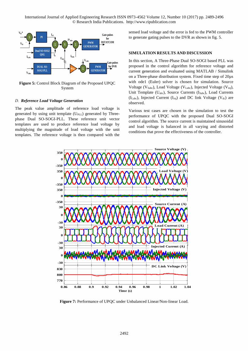
Figure 5: Control Block Diagram of the Proposed UPQC
System
D. Reference Load Voltage Generation
The peak value amplitude of reference load voltage is
generated by using unit template (UPLL) generated by Three-
phase Dual SO-SOGI-PLL. These reference unit vector
templates are used to produce reference load voltage by
multiplying the magnitude of load voltage with the unit
templates. The reference voltage is then compared with the
sensed load voltage and the error is fed to the PWM controller
to generate gating pulses to the DVR as shown in fig. 5.
SIMULATION RESULTS AND DISCUSSION
In this section, A Three-Phase Dual SO-SOGI based PLL was
proposed in the control algorithm for reference voltage and
current generation and evaluated using MATLAB / Simulink
on a Three-phase distribution system. Fixed time step of 20µs
with ode1 (Euler) solver is chosen for simulation. Source
Voltage (VSabc), Load Voltage (VLabc), Injected Voltage (Vinj),
Unit Template (Uabc), Source Currents (ISabc), Load Currents
(ILabc), Injected Current (Iinj) and DC link Voltage (Vdc) are
observed.
Various test cases are chosen in the simulation to test the
performance of UPQC with the proposed Dual SO-SOGI
control algorithm. The source current is maintained sinusoidal
and load voltage is balanced in all varying and distorted
conditions that prove the effectiveness of the controller.
Figure 7: Performance of UPQC under Unbalanced Linear/Non-linear Load.
-350
0
350
-350
0
350
-350
0
350
-30
0
30
-30
0
30
-30
0
30
0.86 0.88 0.9 0.92 0.94 0.96 0.98 1 1.02 1.04
770
800
830
Time (s)
Source Voltage (V)
Load Voltage (V)
Injected Voltage (V)
Source Current (A)
Load Current (A)
Injected Current (A)
DC Link Voltage (V)

International Journal of Applied Engineering Research ISSN 0973-4562 Volume 12, Number 10 (2017) pp. 2489-2496
© Research India Publications. http://www.ripublication.com
2493
Figure 8: Performance of UPQC with Increase in Non-linear Load.
Figure 9: Performance of UPQC under Balanced Voltage Sag (30%).
-350
0
350
-350
0
350
-350
0
350
-30
0
30
-30
0
30
-30
0
30
1.16 1.18 1.2 1.22 1.24 1.26 1.28 1.3 1.32 1.34
770
800
830
Time (s)
Source Voltage (V)
Load Voltage (V)
Injected Voltage (V)
Source Current (A)
Load Current (A)
Injected Current (A)
DC Link Voltage (V)
-350
0
350
-350
0
350
-350
0
350
-30
0
30
-30
0
30
-30
0
30
1.56 1.58 1.6 1.62 1.64 1.66 1.68 1.7 1.72 1.74
770
800
830
Time (s)
Source Voltage (V)
Load Voltage (V)
Injected Voltage (V)
Source Current (A)
Load Current (A)
Injected Current (A)
DC Link Voltage (V)

International Journal of Applied Engineering Research ISSN 0973-4562 Volume 12, Number 10 (2017) pp. 2489-2496
© Research India Publications. http://www.ripublication.com
2494
Figure 10: Performance of UPQC with Unbalance in Grid Voltage.
Figure 11: Performance of UPQC under Grid Voltage Harmonics (5th & 7th).
-350
0
350
-350
0
350
-350
0
350
-30
0
30
-30
0
30
-30
0
30
2.56 2.58 2.6 2.62 2.64 2.66 2.68 2.7 2.72 2.74
770
800
830
Time (s)
Source Voltage (V)
Load Voltage (V)
Injected Voltage (V)
Source Current (A)
Load Current (A)
Injected Current (A)
DC Link Voltage (V)
-350
0
350
-350
0
350
-350
0
350
-30
0
30
-30
0
30
-30
0
30
2.86 2.88 2.9 2.92 2.94 2.96 2.98 3 3.02 3.04
770
800
830
Time (s)
Source Voltage (V)
Load Voltage (V)
Injected Voltage (V)
Source Current (A)
Load Current (A)
Injected Current (A)
DC Link Voltage (V)

International Journal of Applied Engineering Research ISSN 0973-4562 Volume 12, Number 10 (2017) pp. 2489-2496
© Research India Publications. http://www.ripublication.com
2495
Figure 12: Performance of UPQC with DC Offset (10%) in Grid Voltage.
CONCLUSION
A simple control algorithm with dual second-order SOGI
based PLL for three - phase UPQC has been tested and
validated using MATLAB / Simulink. This theory is adopted
to work in sinusoidal and non-sinusoidal grid voltages such as
balanced and unbalanced sag, harmonics and load conditions
such as unbalance, harmonics and increase in load. The source
current is maintained within IEEE 519-1992 limits. The
control algorithm is very effective and easy to implement
because of simple equations involved in it compared to those
proposed in the literature. SO-SOGI - PLL has proved its
efficiency under all adverse conditions with its simple
structure and accuracy. The source and load balancing,
reactive current and harmonic compensation is effectively
done under steady-state and dynamic conditions prove the
controller performance.
REFERENCES
[1] F. F. Ewald and A. S.M.Mohammad, Power Quality in Power Systems and Electrical Machines. London, U.K.:
Elsevier Academic Press, 2008.
[2] Gz. Arindam and L. Gerard, Power Quality Enhancement using Custom Power Devices, Springer
International Edition ed. Delhi, India: springer, 2009.
[3] C. Sankaran, Power Quality. Boca Raton, FL: CRC,
2001.
[4] IEEE Recommended Practices and requirement for Harmonic Control on electric power System, IEEE
Standard 519, 1992.
[5] Bollen. M. “Understanding power quality problems voltage sag and interruption” (IEEE Press, Piscataway,
NJ, 1999).
[6] Baggini A.“Handbook of power quality” (John Wiley &
Sons Ltd, 2008).
[7] T. Devaraju, V. C. Veera Reddy, and M. Vijaya Kumar,
“Role of custom power devices in power quality
enhancement: a review,” International Journalof Engineering Scienceand Technology, Vol.2, No. 8, pp.
3628-3634, 2010
[8] J.S. Hsul, “Instantaneous phasor method for obtaining
instantaneous balanced fundamental components for
power quality control and continuous diagnostics,” IEEE Trans. Power Del., vol. 13, no. 4, pp.1494–1500, Oct.
1998.
[9] H. Akagi et al., “Instantaneous reactive power
compensator comprising switching devices without
energy storage components,” IEEE Trans. Ind. Appl., vol. IA-20, no. 3, pp. 625–630, May/Jun. 1984.
-350
0
350
-350
0
350
-350
0
350
-30
0
30
-30
0
30
-30
0
30
3.16 3.18 3.2 3.22 3.24 3.26 3.28 3.3 3.32 3.34
770
800
830
Time (s)
Source Voltage (V)
Load Voltage (V)
Injected Voltage (V)
Source Current (A)
Load Current (A)
Injected Current (A)
DC Link Voltage (V)

International Journal of Applied Engineering Research ISSN 0973-4562 Volume 12, Number 10 (2017) pp. 2489-2496
© Research India Publications. http://www.ripublication.com
2496
[10] Yash pal, A.Swarup, Bhim Singh., “Comparison of three control algorithms for Single-Phase UPQC” in Proc.
2011 International conference on Energy, Automation
and Signal, Dec, 2011.
[11] V. Kaura and V. Blasko, “Operation of a phase locked loop system under distorted utility conditions” Industry Applications, IEEE Transactions on, vol. 33, no. 1, pp.
58-63, 1997.
[12] Masoud Karimi-Ghartemani, “ A Unifying Approach to Single-Phase Synchronous Reference Frame PLLs”,
IEEE Trans. Power Electron., 2013, 28, (10), pp. 4550–
4556.
[13] M. Ciobotaru, R. Teoderescu, and F. Blaabjerg, “A new single-phase PLL structure based on second order
generalized integrator” in Proc.37th IEEE PESC, Jun.
2006.
[14] Z Xin, X Wang, Z Qin, P C Loh, F. Blaabjerg, “An
Improved Second-Order Generalized Integrator Based
Quadrature Signal Generator”, IEEE Trans. Power Electron., vol. 27, no. 1, pp. 99–112, Jan. 2012.
[15] Yada, Hareesh Kumar, and M. S. R. Murthy. “A new topology and control strategy for extraction of reference current using single phase SOGI-PLL for three-phase four-wire Shunt Active Power Filter”, 2014 IEEE
International Conference on Power Electronics Drives
and Energy Systems (PEDES), 2014.
APPENDIX
AC Supply Source & Frequency Three-Phase, 415 V, 50Hz
Source Impedance Rs=0.05 Ω, Ls =0.05mH
Non-Linear Load RL=24 Ω, L=0.06H
Rating of Transformer 5 KVA, 1:1 ratio
Switching frequency 8kHz
Reference dc bus voltage 800V
Interfacing inductor Ls=3.5mH
Gains of PI controller for dc bus Kp =0.4, Ki=6
Gains of SO-SOGI K1=1, K2=1.6 Gains of PI controller for SO-SOGI-PLL Kp =67.5, Ki=100
THD (%) of Test Cases (Table-I)
Fig No. Vsa VLa Isa ILa
6 0.82 0.44 2.11 21.02
7 0.85 0.77 1.44 13.44
8 0.32 0.65 1.67 19.12
9 0.2 0.95 1.95 21.18
10 0.11 0.9 1.91 21.24
11 24.07 1.24 3.46 21.22
12 0.11 0.67 3.19 21.17


![Mitigation of Voltage and Current Harmonics Using UPQC ... · were obtained to verify those active power flow issues in a harmonic free electrical System. REFERENCES [1].JinweiHe,YunWei](https://static.fdocuments.in/doc/165x107/5f14f274fcf64a76b65b9773/mitigation-of-voltage-and-current-harmonics-using-upqc-were-obtained-to-verify.jpg)


