
A Division of A A Manufacturing Co. Inc. DEsign guiDE:...
26
halltech.com DESIGN GUIDE: PRECISION SLIP CLUTCHES • Continuous Slip Mechanical Clutches • Pneumatic Slip Clutches • Jaw Clutches • One Way Clutches A Division of A & A Manufacturing Co. Inc.
-
Upload
truongkhanh -
Category
Documents
-
view
213 -
download
0
Transcript of A Division of A A Manufacturing Co. Inc. DEsign guiDE:...

halltech.com
DEsign guiDE: PreciSiOn SLiP cLutcheS• Continuous Slip Mechanical Clutches • Pneumatic Slip Clutches • Jaw Clutches• One Way Clutches
A Division of A&A Manufacturing Co. Inc.

Page 1
cOntinuOuS slip clutchEs SOLVE MANY DESIGN ENGINEERING PRObLEMSPolyclutch® slip clutches can slip continuously or intermittently for over 30 million cycles. This opens up many design engineering options including...
TENSION CONTROL Maintain constant tension while winding or unwinding wire, paper, film, thread, etc. Slip clutch automatically compensates for changes in speed and diameter. Pneumatic clutch can change tension during operation.
TORQUE CONTROL Screw bottle caps, screws, controls, etc., to correct torque setting. Combine with one way clutch to slip at rated torque in one direction and freewheel or positive drive in other direction.
INDEXING Hold index wheel with solenoid operated pin. Motor runs continuously with clutch slipping. Pin pulls back to index to next station. Can be single or partial revolution. Can index tables, conveyors, vending machines, controls, etc.
OVERLOAD PROTECTION Protect machinery and operator. Clutch will slip when mechanism is jammed. Motion will continue when impediment is removed.
FORC E CONTROL Push product against gate with constant force. Remove gate and move to next position. No damage to product or conveyor – clutch does all the slipping. Also used for overload protection when jammed and for indexing the conveyor.
POSITION RETENTION AND bRAKE Hold lid, cover, door, screen, etc., at any position. Fingertip control. Combine with one way clutch for free movement in one direction.
SOFT STARTS/CUSHIONED STOPS Inertia makes clutch slip when starting and/or stopping. Results in less shock throughout the system. Ideal for slip at the end of stroke.

Page 2
AbOut polyclutch®
prEcision clutchEs
APPLICATIONS:
• Overload Protection (machine and personnel safety)
• Torque Control (bottle capping, fastener driving)
• Tension Control (printing, stamping, feed and take-up reels)
• Brake – Position retention (covers)
KEY bENEFITS:
• Smooth Breakaway and continuous slip
• Long life of 20 to 30 million cycles in slip condition
• Torque range from 0.5 lb-in to 750 lb-in
• Fixed, adjustable and custom designs
• Clutches are bi-directional
• No lubrication needed
• Made in the USA
A GREAT ALTERNATIVE TO:
• Servo-Motors: our solution costs less
• Magnetic Clutches: smaller, less expensive
• Ball detent: no clicking, no reset required
• Torque limiters: consistent repeatability, continuous
• Electronic protection only: added mechanical safety in electronically controlled systems
LIMITATIONS:
• Maximum 1.25” shaft size on a through-shaft
• Not to be used as a universal joint or a spring coupler
• Does not de-couple at overload
• Cannot be exposed to radiation
• Contact a Polyclutch application specialist if slip clutch would be directly exposed to weather or wash down
POLYCLUTCH ELIMINATES STICTIONPolyclutch has developed a unique technology and manufacturing process resulting in static friction being lower than dynamic friction. This characteristic generates repeatable torque control and smooth operation while slipping.
• No sudden shock on sensitive paper, film, wire, thread, etc.
• Repeatable cushioned torque for protection during overload
• Ideal for friction hinges when smooth movement of lids, doors, screens, covers, etc., is required
• Smooth, accurate starting/stopping of conveyors, indexing mechanisms, linear actuator, etc.
• Repeatable accurate torque for capping machines, automatic screw driving, valve control, etc.
Our proprietary burn-in process ensures that all Polyclutch slip clutches will perform consistently right out of the box, with no break-in period required.

Page 3
POLYCLUTCH EXTENDS MACHINERY LIFEPolyclutch® adjustable slip clutches control the precise amount of torque to tighten bottle caps, without wear or breakage, in this capping line application. All the slippage is in the clutch, with no appreciable wear.
APPLicAtiOn ExAMplEs
CONSTANT TORQUE GIVES YOU THE SLIP A slip clutch acts as a continuous drag brake to meet the specific torque requirement for this unwind/rewind system application in a DATAMAX® bar code printer.
Other applications apply constant tension to film, wire, thread, paper, etc.

Page 4
APPLicAtiOn ExAMplEs
AUTOMATED KIOSKSPolyclutch® slip clutches are an integral part of many retail kiosks. As shown in this photo, a slip clutch is used to protect the sensitive drive mechanisms of these automated machines.
HANDICAP ACCESSIbILITY EQUIPMENTA Polyclutch® slip clutch provides safety in many handicap accessibility applications, as seen in this photo, where it is being used for overload protection in an automated door opener.

Page 5
APPLicAtiOn ExAMplEs
ICE-DISPENSING MACHINESHidden deep inside of this ice-making machine, a Polyclutch® slip clutch prevents overload to the drive mechanism during the forming and dispensing of ice cubes.
RETAIL VENDING KIOSKSA Polyclutch® protects this machine against any type ofoverload or jamming during the process of dispensing a DVD.
MRI bEDSPolyclutch® adds a mechanical safety formoving MRI beds as seen in this picture.

Page 6
APPLicAtiOn ExAMplEs
MILITARY & LAW ENFORCEMENTINSPECTION RObOTSThe Machine Lab, Inc., an industryleader in defense robotics, uses twoPolyclutch slip clutches in each robotarm for overload protection.
CONVEYORSPolyclutch® slip clutches offer an added level of safety and protection to both the machine and its operators.
LAbEL PRINTERSPolyclutch® slip clutches are theperfect solution for adding just theright amount of tension to any reelor spool without having to worryabout the tension varying over time or wearing out prematurely.
7Page
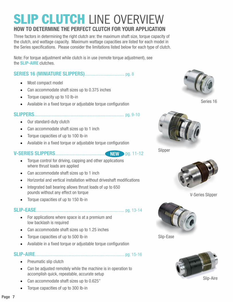
SLiP cLutch linE ovErviEwHOW TO DETERMINE THE PERFECT CLUTCH FOR YOUR APPLICATION
Series 16
Slipper
V-Series Slipper
Slip-Ease
Slip-Aire
Three factors in determining the right clutch are: the maximum shaft size, torque capacity of the clutch, and wattage capacity. Maximum wattage capacities are listed for each model in the Series specifications. Please consider the limitations listed below for each type of clutch.
Note: For torque adjustment while clutch is in use (remote torque adjustment), see the SLIP-AIRE clutches.
SERIES 16 (MINIATURE SLIPPERS)............................... pg. 8
• Most compact model
• Can accommodate shaft sizes up to 0.375 inches
• Torque capacity up to 10 lb-in
• Available in a fixed torque or adjustable torque configuration
SLIPPERS...................................................................... pg. 9-10
• Our standard-duty clutch
• Can accommodate shaft sizes up to 1 inch
• Torque capacities of up to 100 lb-in
• Available in a fixed torque or adjustable torque configuration
V-SERIES SLIPPERS...................................................... pg. 11-12• Torque control for driving, capping and other applications
where thrust loads are applied
• Can accommodate shaft sizes up to 1 inch
• Horizontal and vertical installation without driveshaft modifications
• Integrated ball bearing allows thrust loads of up to 650 pounds without any effect on torque
• Torque capacities of up to 150 lb-in
SLIP-EASE..................................................................... pg. 13-14
• For applications where space is at a premium and low backlash is required
• Can accommodate shaft sizes up to 1.25 inches
• Torque capacities of up to 500 lb-in
• Available in a fixed torque or adjustable torque configuration
SLIP-AIRE...................................................................... pg. 15-16
• Pneumatic slip clutch
• Can be adjusted remotely while the machine is in operation to accomplish quick, repeatable, accurate setup
• Can accommodate shaft sizes up to 0.625”
• Torque capacities of up to 300 lb-in
NEW

Page 8
42 53P F S 16 - 4 T*
4⁄16 = .250" bore dia. in clutch cartridge and housing
Size 16 = 16⁄16 (1" outside dia.)
Shaft to shaft installation type
Fixed torque (factory preset)
Single-Plate Slipper
1
PART NUMbER EXAMPLE (see p. 19 for part no. identification)
MechAnicAL slip clutchEsSERIES 16 (MINIATURE SLIPPERS)
[METRIC]Model Number A b std. b max. C D E Nm Watts
FrictionSurfaces
SFS 16 & SFO 16 SAS 16 & SAO 16
25.40 8 10 25.4033.27
19.30 6.35 1.2 6 8
PFS 16 & PFO 16PAS 16 & PAO 16
25.40 8 10 19.8126.92
19.30 6.35 .3 1 2
[S.A.E.]Model Number A b std. b max. C D E lb-in Watts
FrictionSurfaces
SFS 16 & SFO 16 SAS 16 & SAO 16
1.00 .250 .375 1.00 1.31
.760 .25 10 6 8
PFS 16 & PFO 16PAS 16 & PAO 16
1.00 .250 .375 .78 1.06
.760 .25 2 1 2
Our most compact model features big torque in a small package.
Capacity @ 50 RPM+.002 / -.000 IN
Capacity @ 50 RPM+.05 / -.00 MM
shaft-through version shownoil impregnated bronze bearing in housingadapt pulley, sprocket, frame, etc. to boss
cartridge withadjusting nut
shaft to shaft version shownset screws in housing shafts must bein line within .020” and supported
cartridge withfixed collar (factory set)
Dhousing boss
diameter
CO. A. L.
Aoutside
diameter
Aoutside
diameter
Dhousing boss
diameter
Ehousing
bosslength
CO. A. L. B
bore diameterEhousing
bosslength
ADJUSTABLESAO SAS PAO PAS
SAO SHOWN
FIXEDFACTORY SET - NON ADJUSTABLE
SFO SFS PFO PFSSFS SHOWN
END VIEWTYPICAL
See pages 17-18 for slip clutch operation (construction, installation, capacity) and mounting options.
*T= Preset Torque Value
Page 9
Gtorque pinbolt circle
cartridge withfixed collar (factory set)
Htorque pindiametershaft-through version shown
oil impregnated bronze bearing in housingadapt pulley, sprocket, frame, etc. to boss
cartridge withadjusting nut
shaft to shaft version shownset screws in housing shafts mustbe in line within .020” and supported
borediameter
Dhousing boss
diameter
Aoutside
diameter
Dhousing boss
diameter
CO.A.L.
EEclutch
housinglength
Ehousing
boss length
Fclutch
cartridgelength BE
housingboss length
EEclutch
housinglength
Fclutch
cartridgelength
CO.A.L.
Aoutside
diameter
ADJUSTABLESAO SAS PAO PAS
SAO SHOWN
FIXEDFACTORY SET - NON ADJUSTABLE
SFO SFS PFO PFSSFS SHOWN
END VIEWTYPICAL
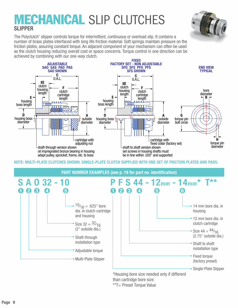
NOTE: MULTI-PLATE CLUTCHES SHOWN. SINGLE-PLATE CLUTCH SUPPLIED WITH ONE SET OF FRICTION PLATES AND PADS.
42 53S A O 32 - 10
10⁄16 = .625" bore dia. in clutch cartridge and housing
Size 32 = 32⁄16(2" outside dia.)
Shaft-through installation type
Adjustable torque
Multi-Plate Slipper
1
PART NUMbER EXAMPLES (see p. 19 for part no. identification)
42 53P F S 44 - 12mm - 14mm* T**
14 mm bore dia. in housing
12 mm bore dia. inclutch cartridge
Size 44 = 44⁄16(2.75" outside dia.)
Shaft to shaftinstallation type
Fixed torque(factory preset)
Single-Plate Slipper
1
*Housing bore size needed only if different than cartridge bore size.**T= Preset Torque Value
6
MechAnicAL slip clutchEsSLIPPER The Polyclutch® slipper controls torque for intermittent, continuous or overload slip. It contains a number of brass plates interfaced with long life friction material. Soft springs maintain pressure on the friction plates, assuring constant torque. An adjacent component of your mechanism can often be used as the clutch housing reducing overall cost or space concerns. Torque control in one direction can be achieved by combining with our one-way clutch.
Page 10
[METRIC]Model Number A b* std. b max. C D E EE F G H Nm Watts
Friction Surfaces
SFS 20 & SFO 20 SAS 20 & SAO 20
31.75 8 10 30.238.1
19.30 6.35 12.70 17.5025.40
26.97 2.38 1.5 6 8
SFS 24 & SFO 24 SAS 24 & SAO 24
38.10 10 13 50.863.5
25.65 9.65 19.05 30.7044.50
33.32 3.18 3 15 12
SFS 32 & SFO 32SAS 32 & SAO 32
50.80 12 16 58.772.9
35.18 12.70 25.04 33.3047.80
42.47 4.78 6 30 12
SFS 44 & SFO 44 SAS 44 & SAO 44
69.85 12 16 58.772.9
41.53 12.70 25.04 33.3047.80
60.33 4.78 9 43 12
SFS 48 & SFO 48 SAS 48 & SAO 48
76.20 16 25 76.2 88.9
44.70 12.70 25.40 50.80 63.50
66.80 6.35 11.5 55 12
PFS 20 & PFO 20PAS 20 & PAO 20
31.75 8 10 19.826.9
19.30 4.83 7.87 11.9019.10
26.97 2.38 .3 1 2
PFS 24 & PFO 24PAS 24 & PAO 24
38.80 10 13 27.033.5
25.65 4.83 9.65 17.5023.90
33.32 3.18 .5 2 2
PFS 32 & PFO 32PAS 32 & PAO 32
50.80 12 16 31.043.7
35.18 6.35 12.70 18.3031.00
42.47 4.78 1 5 2
PFS 44 & PFO 44PAS 44 & PAO 44
69.85 12 16 31.043.7
41.53 6.35 12.70 18.3031.00
60.33 4.78 1.5 7 2
PFS 48 & PFO 48 PAS 48 & PAO 48
76.20 16 25 57.15 69.85
44.70 12.70 25.40 31.75 44.45
66.80 6.35 2.4 13 2
[S.A.E.]Model Number A b* std. b max. C D E EE F G H lb-in Watts
Friction Surfaces
SFS 20 & SFO 20 SAS 20 & SAO 20
1.25 .250 .375 1.19 1.50
.760 .25 .50 .69 1.00
1.062 .094 12 6 8
SFS 24 & SFO 24 SAS 24 & SAO 24
1.50 .375 .500 2.00 2.50
1.010 .38 .75 1.21 1.75
1.312 .125 25 15 12
SFS 32 & SFO 32SAS 32 & SAO 32
2.00 .500 .625 2.312.87
1.385 .50 1.00 1.311.88
1.672 .188 50 30 12
SFS 44 & SFO 44 SAS 44 & SAO 44
2.75 .500 .625 2.312.87
1.635 .50 1.00 1.311.88
2.375 .188 75 43 12
SFS 48 & SFO 48 SAS 48 & SAO 48
3.00 .625 1.00 3.003.50
1.760 .50 1.00 2.002.50
2.625 .250 100 55 12
PFS 20 & PFO 20PAS 20 & PAO 20
1.25 .250 .375 .781.06
.760 .19 .31 .47.75
1.062 .094 2.5 1 2
PFS 24 & PFO 24PAS 24 & PAO 24
1.50 .375 .500 1.071.32
1.010 .19 .38 .69.94
1.312 .125 4 2 2
PFS 32 & PFO 32PAS 32 & PAO 32
2.00 .500 .625 1.221.72
1.385 .25 .50 .721.22
1.672 .188 8 5 2
PFS 44 & PFO 44PAS 44 & PAO 44
2.75 .500 .625 1.221.72
1.635 .25 .50 .721.22
2.375 .188 12 7 2
PFS 48 & PFO 48PAS 48 & PAO 48
3.00 .625 1.00 2.252.75
1.760 .50 1.0 1.25 1.75
2.625 .250 20 13 2
Capacity @ 50 RPM
Capacity @ 50 RPM
+.002 / -.000 IN
+.05 / -.00 MM
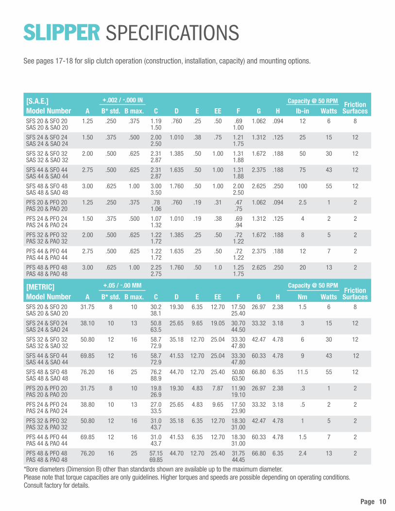
SLiPPer spEciFicAtionsSee pages 17-18 for slip clutch operation (construction, installation, capacity) and mounting options.
*Bore diameters (Dimension B) other than standards shown are available up to the maximum diameter. Please note that torque capacities are only guidelines. Higher torques and speeds are possible depending on operating conditions. Consult factory for details.

Page 11
42 53V A S 20 - 4
4⁄16 = .250" bore dia. in clutch cartridge and housing
Size 20 = 20⁄16(1.25" outside dia.)
Shaft to shaft installation type
Adjustable torque
V-Series Slipper
1
PART NUMbER EXAMPLES (see p. 19 for part no. identification)
42 53V A S 44 - 12mm - 10mm*
10 mm bore dia. in housing
12 mm bore dia.in clutch cartridge
Size 44 = 44⁄16(2.75" outside dia.)
Shaft to shaft installation type
Adjustable torque
V-Series Slipper
1 6
MechAnicAL slip clutchEsV-SERIES SLIPPERThe V-Series Slipper provides torque control for driving, capping and other applications where thrust loads are applied. Its integrated ball bearing allows thrust loads up to 650 pounds without any effect on torque. Self-supporting hub design allows for easy installation; shaft-through support is not required. The V-Series slipper may be used for pulley applications; and its design allows rebuilding, if necessary.
Gtorque pinbolt circle
torque pindiameter
H
Ehousing
bosslength
CO. A. L.
Aoutside
diameter
Fclutch cartridge
length
cartridge withadjusting nut
shaft to shaft version shownadapt driver or chuck tohousing bore or housing boss
output borediameter
BB
BBDoutput bore
depth
BDinput bore
depth
input borediameter
B
ADJUSTABLEVAS SHOWN
END VIEWTYPICAL
END VIEWTYPICAL
Dhousing boss
diameter
*Housing bore size needed only if different than cartridge bore size.
Page 12
[S.A.E.]Model Number A b* std. b max. bD bb** bbD C D E F G H
VAS 20 1.25 .250 .375 .750 .250 .500 2.05 .750 .350 .98 1.062 .094
VAS 24 1.50 .375 .500 1.25 .250 .500 2.85 1.000 .375 1.69 1.312 .125
VAS 32 2.00 .500 .625 1.25 .250 .500 3.00 1.375 .500 1.80 1.672 .188
VAS 44 2.75 .500 .625 1.25 .250 .500 3.30 1.625 .500 1.80 2.375 .188
VAS 48 3.00 .625 1.000 1.75 .250 .500 4.00 1.750 .500 2.43 2.625 .250
Model Number lbs. N lb-in Nm WattsFrictionSurfaces
VAS 20 165 22.8 12 1.5 6 8
VAS 24 255 35.3 25 3 15 12
VAS 32 300 41.5 50 6 30 12
VAS 44 400 55.3 75 9 43 12
VAS 48 665 91.9 100 11.5 55 12
[METRIC]Model Number A b* std. b max. bD bb** bbD C D E F G H
VAS 20 31.75 8 10 19.05 6.35 12.07 52.07 19.05 8.89 24.89 26.97 2.39
VAS 24 38.10 10 13 31.75 6.35 12.07 72.39 25.40 9.53 42.93 33.32 3.18
VAS 32 50.80 12 16 31.75 6.35 12.07 76.20 34.93 12.70 45.72 42.47 4.78
VAS 44 69.85 12 16 31.75 6.35 17.78 83.82 41.28 12.70 45.72 60.33 4.78
VAS 48 76.20 16 25 44.45 6.35 17.78 101.60 44.45 12.70 61.72 66.80 6.35
Capacity @ 50 RPMThrust Load
+.002 / -.000 IN +.002 / -.000 IN
+.05 / -.00 MM +.05 / -.00 MM
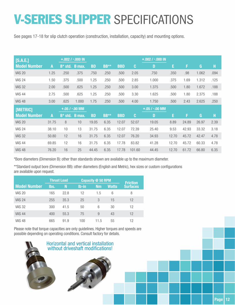
Please note that torque capacities are only guidelines. Higher torques and speeds are possible depending on operating conditions. Consult factory for details.
*Bore diameters (Dimension B): other than standards shown are available up to the maximum diameter.
**Standard output bore (Dimension BB): other diameters (English and Metric), hex sizes or custom configurations are available upon request.
v-SerieS SLiPPer spEciFicAtionsSee pages 17-18 for slip clutch operation (construction, installation, capacity) and mounting options.
Horizontal and vertical installationwithout driveshaft modifications!

Features:• Extremely small, 3/4” outside diameter
• Torque ranges up to 8.5 lb-in
• Durable, proven, low backlash housing design
• Stainless steel options available
• Fixed, adjustable and custom designs
• Smooth, reliable breakaway and continuous slip
• Long life of 20 to 30 million revolutions in slip condition
• Bi-directional
• No lubrication needed
• Made in the USA
New – series 12 | SLip-EASE MEchANicAL SLip cLUTchES
ERFS 12 Fixed clutch
EAO 12 Adjustable clutch
For ultra small spacesOur smallest available slip clutch for applications where space is at a premium anda robust reliable solution is needed.
applicatioN eXamples:• Medical devices – fluid analyzer
• Dental instruments – implant torque wrench
• Robotics – overload protection for cameras
• Automation – miniature drive protection
caD drawings and models available on our website:www.polyclutch.com/technical-data/cad-drawings

Capacity @ 50 RPM
Model NuMber Ainches (mm)
b* std.inches (mm)
b* max.inches (mm)
Cinches (mm)
d*inches (mm)
einches (mm) lb-in (Nm) Watts Friction
SurfacesEAO 12 0.750 (19.05) 0.1875 (5) 0.250 (6) 1.25 (31.75) 0.562 (14.28) 0.188 (4.78) 8.5 (1.0) 4.5 8EAS 12 0.750 (19.05) 0.1875 (5) 0.250 (6) 1.25 (31.75) 0.562 (14.28) 0.188 (4.78) 8.5 (1.0) 4.5 8EFO 12 0.750 (19.05) 0.1875 (5) 0.250 (6) 1.00 (25.40) 0.562 (14.28) 0.188 (4.78) 8.5 (1.0) 4.5 8EFS 12 0.750 (19.05) 0.1875 (5) 0.250 (6) 1.00 (25.40) 0.562 (14.28) 0.188 (4.78) 8.5 (1.0) 4.5 8
* +0.002 / -0.000 inches (+0.05 / -0.00 mm) Note: Bore diameters other than shown are available up to the maximum diameter.
series 12 | DESigN SpEciFicATiONS
pArt NuMber exAMple
e a s 12 – 3 – 4*
4⁄16 = 0.250" bore diameter in housing
3⁄16 = 0.1875" bore diameter in cartridge
Size 12 = 12⁄16 (0.75" outside diameter)
Shaft to shaft installation type
Adjustable torque
Slip-Ease
*housing bore size needed only if different than cartridge bore size.
polyclutch Division | www.polyclutch.comA&A Manufacturing co., inc,phone: (262) 786-1500 or (800) 298-2066Email: [email protected]
eas & eao models: adjustable torque settingeFo & eFs models: factory preset (fixed) torque settingeas & eFs models: shaft to shaft installation type. provided with set screws in clutch housingeao & eFo models: shaft-through mounting to pulley, gear, sprocket, etc. provided with oil impregnated bearingin clutch housing
desigN Notes
Adjustable EAO & EASEAO shown
FixedEFO & EFS
Factory Set - Non AdjustableEFS shown
End ViewTypical
shaft to shaft version shownset screws in housingshafts must be in linewithin .020” and supported
cartridge with�xed collar (factory set)
Dboss
diameter
Eboss
length
CO.A.L.
Aoutsidediameter
Bborediameter
Aoutsidediameter
Dboss
diameter
Eboss
length
CO.A.L.
shaft through version shownoil impregnated bronze bearing in housingadapt pulley, sprocket, frame, etc. to boss
cartridgeadjusting nut
Page 13
6
PART NUMbER EXAMPLES (see p. 19 for part no. identification)
42 53E F O 44 - 12mm
12 mm bore dia. in clutch cartridge and housing
Size 44 (relative size)2.25" outside dia.
Shaft-throughinstallation type
Fixed torque(factory preset)
Slip-Ease
1
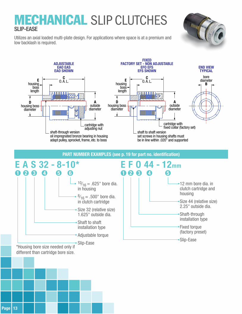
MechAnicAL slip clutchEsSLIP-EASEUtilizes an axial loaded multi-plate design. For applications where space is at a premium and low backlash is required.
shaft to shaft versionset screws in housing shafts mustbe in line within .020” and supported
cartridge withfixed collar (factory set)
ADJUSTABLEEAO EAS
EAO SHOWN
FIXEDFACTORY SET - NON ADJUSTABLE
EFO EFSEFS SHOWN
Dhousing boss
diameter
Ehousing
bosslength
CO. A. L.
Aoutside
diameter
Aoutside
diameter
Dhousing boss
diameter
Ehousing
bosslength
CO. A. L.
shaft-through versionoil impregnated bronze bearing in housingadapt pulley, sprocket, frame, etc. to boss
cartridge withadjusting nut
borediameter
B
END VIEWTYPICAL
42 53E A S 32 - 8-10*
10⁄16 = .625" bore dia.in housing8⁄16 = .500" bore dia. in clutch cartridge
Size 32 (relative size)1.625" outside dia.
Shaft to shaftinstallation type
Adjustable torque
Slip-Ease
1
*Housing bore size needed only if different than cartridge bore size.

Page 14
[METRIC]Model Number A b* std. b max. C D E Nm Watts
Friction Surfaces
EFS 16 & EFO 16 25.40 8 10 30.2 19.05 6.35 2 9 12
EAS 16 & EAO 16 25.40 8 10 38.1 19.05 6.35
EFS 24 & EFO 24 34.90 10 13 50.8 25.40 9.65 3 15 12
EAS 24 & EAO 24 34.90 10 13 63.5 25.40 9.65
EFS 32 & EFO 32 41.28 12 16 47.5 34.93 12.70 6 30 12
EAS 32 & EAO 32 41.28 12 16 62.0 34.93 12.70
EFS 44 & EFO 44 57.15 12 16 47.5 41.28 12.70 9 43 12
EAS 44 & EAO 44 57.15 12 16 62.0 41.28 12.70
EAS 52 & EAO 52 82.55 20 32 101.6 50.80 12.70 17** 85 12
[S.A.E.]Model Number A b* std. b max. C D E lb-in Watts
Friction Surfaces
EFS 16 & EFO 16 1.000 .250 .375 1.19 .750 .25 16 9 12
EAS 16 & EAO 16 1.000 .250 .375 1.50 .750 .25
EFS 24 & EFO 24 1.375 .375 .500 2.00 1.000 .38 25 15 12
EAS 24 & EAO 24 1.375 .375 .500 2.50 1.000 .38
EFS 32 & EFO 32 1.625 .500 .625 1.87 1.375 .50 50 30 12
EAS 32 & EAO 32 1.625 .500 .625 2.44 1.375 .50
EFS 44 & EFO 44 2.250 .500 .625 1.87 1.625 .50 75 43 12
EAS 44 & EAO 44 2.250 .500 .625 2.44 1.625 .50
EAS 52 & EAO 52 3.250 .750 1.250 4.00 2.000 .50 150** 85 12
+.05 / -.00 MM
Capacity @ 50 RPM+.002 / -.000 IN
Capacity @ 50 RPM
SLiP-eASe spEciFicAtions
*Bore diameters (Dimension B): other than standards shown are available up to the maximum diameter.
**Maximum capacity is 500 lb-in / 56 Nm. Heat generation should not exceed maximum Watts capacity. Watts = Torque x RPM x Duty Cycle x 0.011
See pages 17-18 for slip clutch operation (construction, installation, capacity) and mounting options.

Page 15
PneuMAtic slip clutchEs SLIP-AIREThe Polyclutch® Slip-Aire is an air actuated version of the mechanical Polyclutch® slip clutch. It has the same long life friction plates, assuring constant torque or tension. With air actuation it can be used to engage/disengage, to vary the torque during operation, or to adjust the torque remotely at any time. Ideal for servo mechanisms, it transmits higher torque levels than comparably sized mechanical slip clutches.
AAO - Shaft-Through Versionoil impregnated bronzebearing in housingadapt pulley, sprocket, gear, frame, etc, to housing boss
AAS - Shaft-to-Shaft Versionset screws in housingshafts must be in line within.020 and supported
borediameter
B
Jair inlet threadstraight thread - gasket required
Aoutside
diameter
H - torque pin diameterG - torque pin bolt circle (3 places, equally spaced)
Dboss
diameter
Fcartridgelength
EEhousinglength
Eboss
length
CO.A.L.
END VIEWTYPICAL
6
PART NUMbER EXAMPLES (see p. 19 for part no. identification)
42 53A A 0 20 - 4
16 mm bore dia.in clutch housing
12 mm bore dia.in clutch cartridge
Size 32 = 32⁄16 (2"outside dia.)
Shaft to shaft installation type
Adjustable torque
Slip-Aire
142 53
A A S 32 - 12mm-16mm*
4⁄16 = .250" bore dia. in clutch cartridge and housing
Size 20 = 20⁄16 (1.25" outside dia.)
Shaft-throughinstallation type
Adjustable torque
Slip-Aire
1
*Housing bore size needed only if different than cartridge bore size.

Page 16
[S.A.E.]Model Number A b* std. b max. C D E EE F G H JAAS 20 & AAO 20 1.25 .250 .375 2.50 .760 .25 .50 2.00 1.062 .094 10-32
AAS 24 & AAO 24 1.50 .375 .500 3.38 1.010 .38 .75 2.63 1.312 .125 10-32
AAS 32 & AAO 32 2.00 .500 .625 3.63 1.385 .50 1.00 2.63 1.672 .188 10-32
AAS 44 & AAO 44 2.75 .500 .625 3.63 1.635 .50 1.00 2.63 2.375 .188 10-32
[METRIC]Model Number A b* std. b max. C D E EE F G H JAAS 20 & AAO 20 31.75 8 10 63.50 19.30 6.35 12.70 50.80 26.98 2.39 10-32
AAS 24 & AAO 24 38.10 10 13 85.85 25.65 9.65 19.05 66.80 33.73 3.18 10-32
AAS 32 & AAO 32 50.80 12 16 92.20 35.18 12.70 25.40 66.80 42.47 4.78 10-32
AAS 44 & AAO 44 69.85 12 16 92.20 41.53 12.70 25.40 66.80 60.33 4.78 10-32
+.05 / -.00 MM
Model Number lb-in lb-in Nm Nm WattsFrictionSurfaces
AAS 20 & AAO 20 12 20 1.5 2.2 6 8
AAS 24 & AAO 24 25 50 3.0 6.0 15 12
AAS 32 & AAO 32 50 100 6.0 12.0 30 12
AAS 44 & AAO 44 75 300 9.0 34.0 43 12
continuous@ 50 RPM
CAPACITYmaximum
@ 100 PSIcontinuous
@ 50 RPM
CAPACITYmaximum
@ 100 PSI
+.002 / -.000 IN
1 Rated torque for continuous operation at 50 RPM. Torque can be higher or lower depending on actual RPM and duty cycle.
2 Maximum torque attainable (at 100 PSI).
1 21 2
SLiP-Aire spEciFicAtions
*Bore diameters (Dimension B): other than standards shown are available up to the maximum diameter.
See pages 17-18 for slip clutch operation (construction, installation, capacity) and mounting options.

Page 17
SLiP cLutch opErAtionCONSTRUCTION, INSTALLATION & CAPACITY
CONSTRUCTION A Polyclutch® consists of two parts: a cartridge and a housing (see above).
The cartridge is set screwed or keyed to the input shaft.• The cartridge includes the clutch pack: outer
plates, friction pads, inner plates• Plates are brass with a proprietary finish• Inner plates are keyed to the cartridge hub• Outer plates are keyed to the cartridge housing• Friction pads are a proprietary plastic-based
composite (no asbestos)
The housing is either set screwed or keyed to the output shaft, or (as shown), attached to the output gear or pulley, with a bronze bearing to allow relative motion between the input shaft and the output gear/pulley.
Torque is controlled by changing the pressure applied to the clutch pack. In an adjustable style clutch, the torque level is controlled by compressing the springs with the adjusting nut. In a fixed style clutch, a collar is attached to the hub in a fixed position, and the torque level is set by pushing and locking the spring collar to a calibrated position.
All slip clutch torques are calibrated to +/- 20% but can be held to closer tolerances.
Backlash of 6° is standard for Slipper models and 2° for the Slip-Ease models. Slipper models can be held to 2° if required.
Our proprietary burn-in process insures that all Polyclutch® Slippers will perform consistently right out of the box, with no break-in period required.
INSTALLATION (see p. 19 for mounting options)Shaft-through versions: Insert input shaft into cartridge and tighten set screws. Insert housing around input shaft, with torque pins engaging holes in outer plates. Input shaft will keep the cartridge and housing aligned.
Shaft to Shaft versions: Insert input shaft into cartridge and tighten set screws. Insert output shaft into housing and tighten set screws. Input and output shafts must be properly journaled with centerlines within +/- .010 T.I.R.
Do not lubricate the clutch. Friction materials are designed to run without additional lubrication. Lubrication will cause a change in torque and erratic behavior. The inherent axial loaded design will keep dirt and dust out of the friction surfaces.
CAPACITYThe clutch capacity is based on continuous operation at 50 RPM for over 25 million cycles. Torque, RPM, duty cycle and life are interdependent. A reduction of any of these will allow an increase in any other. (Running at 25 RPM will allow twice the torque, or running for only 10% of the cycle will allow higher RPM, etc.). The limit is based on heat buildup measured in watts per: Watts = Torque (lb-in) x RPM x Duty Cycle* x 0.011*Percent of the time the clutch is slipping, expressed as a decimal. For example, 0.5 = 50% of the time the clutch is slipping.
Please consult our factory for high torque, high RPM and rapid cycling applications.
HOUSING
SET SCREW TIGHTENED TO FLAT ON INPUT SHAFT
INPUT SHAFT
HUB
ADJUSTING NUT
OUTER PLATE
FRICTION PAD
INNER PLATE
SPRINGS
CARTRIDGE
TORQUE PIN
OUTPUTPULLEY
OUTER PLATES KEYEDTO TORQUE PINS ON HOUSING
INNER PLATES KEYEDTO FLATS ON HUB

Page 18
SLiP cLutch Mounting optionsTYPICAL MOUNTING FOR MECHANICAL AND PNEUMATIC SLIP CLUTCHESAll Polyclutch® slip clutches perform the basic function of controlling the torque between two elements. They can be supplied as a shaft-to-shaft coupling or a shaft to pulley, gear, or sprocket model. Polyclutch custom slip clutches can be provided with non-standard bore sizes, keyways, low backlash or higher torque, minus housings and with pulley, gear or sprocket.
Shaft to ShaftShafts must be supported and aligned within .010-.015
Example 1
Gear/Pulley/Sprocketintegrated as partof cartridge
Supply or rewind spool adapted to housing with knurl, pin, cap screws, set screw, key, etc.
Knob adapted to housing knurl, set screw, pin, etc.
Rotary position holder(hinge)
Machine frame adapted with cap screws to housing
Gear/Pulley/Sprocketadapted to housing with knurl, roll pin, cap screws, etc.
Gear/Pulley/Sprocketmodified with pins for engagementHousing is eliminated
Example 2
Example 3 Example 4
Example 5 Example 6
Example 7 Example 8

19Page
PArt nuMber iDEntiFicAtionHOW TO CREATE A PART NUMbER
1 42 53 6
HOUSING bORE SIZE:Generally represented in sixteenths of an inch. To be used only if different from cartridge bore. For metric, add MM after bore sizes. (e.g., SAS24-4MM-6MM).
CARTRIDGE bORE SIZE:Generally represented in sixteenths of an inch. For metric, add MM after bore size (e.g., SAS24-4MM).
OUTER DIAMETER:Generally represented in sixteenths of an inch, please see specifications for exact dimensions.
INSTALLATION TYPE:“S” is shaft to shaft “O” is shaft-through for mounting to pulley, gear, sprocket, etc."Y" is cartridge only
TORQUE SETTING:“A” is adjustable torque “F” is factory preset (fixed) torque**Please indicate torque value if fixed - 'T' = [lb-in], 'Z' = [oz-in]
TYPE OF SLIP CLUTCH: S = Multi-Plate Slipper P = Single-Plate Slipper V = V-Series SlipperE = Slip-Ease A = Slip-Aire (air-actuated)
STANDARD OPTIONSPolyclutch® Slip Clutches are designed to cover a wide range of solutions. To help better fit the clutch to your specific application, here is a list of standard options:
• Bore size changes – English (inches) and metric (mm)
• High torque option, accomplished by extra springs – “H” part no. suffix
o Will increase capacity of standard adjustable slip clutches by 50% (note: removing springs will lower capacity, increase sensitivity)
• Keyways – English and metric – “K” part no. suffix
• Low backlash in Slipper clutch – “UL” part no. suffix
• Heavy inner plates for extra cooling – “D” part no. suffix
• 303/304 stainless steel construction – “Q” part no. prefix
• Two-plate Slipper clutch – “R” version (part no. begins with “R”)
• Plastic cover for Slipper and Slip-Aire clutches
CUSTOM CLUTCHESIf you are looking for something outside of our standard options, our engineers will work with you to help design a clutch for your specific application.
S A S 24 - 4 - 6

20Page
requeSt For quotE PRECISION SLIP CLUTCHES
q Overload Protection q Torque Control (i.e. bottle capping, screwdriver) q Constant Tension/Force q Brake q Soft Start/Cushioned Stop q Position Retention q Other: __________________________________________________________________________________
Operating Environment: (list specific requirements, # corrosives, water, etc.)__________________________________________________________________________________________
Orientation: q Vertical q Horizontal
Temperature Range: _________________________________________________________________________
Type of Equipment: __________________________________________________________________________
Other Application Information: __________________________________________________________________
Polyclutch part number: (if known) _______________________________________________________________
q Mechanical Slip Clutch q Pneumatic Slip Clutch q One-Way Clutch q Jaw Clutch q Combination
Torque Range: ________________ q lb-in q Nm
Type of Mount: (select one)
q Shaft/Shaft Mounting q Shaft Thru Mounting Input Shaft Diameter: _________________ Input Shaft Diameter: __________________________ Output Shaft Diameter: ________________ Output Type: (gear, pulley, frame...) ________________
q Other: ________________________________________________________________________________
RPM: (at the clutch) __________________________________________________________________________
Duty Cycle: (percentage of the time the clutch will be in slip condition) _____________________________________
Maximum Space Limitations: (envelope size, only if a limitation exists) ____________________________________
Life Requirements: (number of cycles, only if a specification exists) ______________________________________
Date: _______________________________________
Company Name: ______________________________
Contact: _____________________________________
Quantity: ____________________________________
Does your equipment also use protective covers and/or cable/hose carriers? q Yes q No
Address ______________________________________
City _____________________ State/Prov. ___________
Country __________________ Zip/Postal Code _______
Telephone ________________ Fax ________________
Email ________________________________________
CLUTCH INFORMATION
APPLICATION INFORMATION
DESIGNED ANDMANUFACTUREDIN THE U.S . A .
Registered to ISO 9001
Please send the completed form to:
Fax: +49 8122 96 60 167 or Email: [email protected]
To submit a quote request online, go to: www.halltech.com

Page 21
Prevent reversal gearAdapted to housing
Engage and disengage mechanismDrive roll adapted to housing
Phase adjustment shaft to pulleyPulley pressed onto knurled housing
jAw clutchEsPolyclutch® Jaw Type clutches permit extremely simple reliable phase adjustment, and/or engage-release between a shaft and gear, pulley, roller, etc. The D Series is knob operated, the J Series is lever operated. Clutch teeth are precision machined from solid steel blanks, 3° tooth spacing (120 teeth) is standard. Alternate spacing available. All Polyclutch jaw clutches are stronger than the shaft driving them.
Model Number A b C D E F P Q R S KEYDH 20 1.25 .250 1.87 .562 .39 – – – – – –
DK 20 1.25 – – .562 .39 .375 .338 .032 .833 .845 #212
DH 32 2.00 .500 2.50 1.252 .75 – – – – – –
DK 32 2.00 – – 1.252 .75 .750 .703 .048 .890 1.470 #606
DJ 20 (Jaws Only) 1.25 .375 1.10 .560 .39 – – – – – –
DJ 32 (Jaws Only) 2.00 .750 1.95 1.250 .75 – – – – – –
Model Number A b C D E F P Q R S KEYJH 32 2.00 .500 3.37 1.252 .75 .750 – – – – –
JK 32 2.00 – – 1.252 .75 .750 .703 .047 .890 1.625 .187 SQ
DH CLUTCH – WITH HUb
JH CLUTCH – WITH HUb
DK KIT – LESS SHAFT
JK KIT – LESS SHAFT
CE
B
D
A
SR
Q
P
D
AF
Customer shaft will require keyway slotand snap ring grooves
E
C
B
D
AF
Customer provisionfor pivot point required
FP
D
A
RQ
S
E Customer shaft will require keyway slot and snap ring grooves
Customer provision for pivot point required
JAW CLUTCH MOUNTING OPTIONS
DJ – JAWS ONLY
A D B
EC
120 teeth (every 3º)20º included angle

Page 22
POLYCLUTCH® HUb-PAK
One wAy clutchEsHUb-PAK, STEEL HOUSING & SHELL-PAK
SHELL-PAK SPECIFICATIONS Right Drive: Shell drives hub clockwise when viewed from extension end of hub. Torque capacity 8 lb-in. Dimension B = 0.250 (Bore diameter) Dimension D = 0.0625 (Pin diameter) Additional diameters available for OEM quantity orders.
CartridgeNumber
Capacity lb-inMax.
DriveRolls
UseRaceDia.
±.005 A
±.005 AA
+.001 -.000
b
+.03 -.00b
±.005 C
+.003 -.000
D±.005
E±.005
F
G30-4 7 4 .6265/ .6245
.375 n/a .250 4 .015 n/a n/a n/a
E31-4 (L OR R)
12 4 .6265/ .6245
n/a .500 .250 4 .015 .062 .062 .312
E33-4 (L OR R)
18 4 .6265/ .6245
n/a .500 .250 4 .015 .062 .062 .312
Housing Number
±.005 G
±.005 H
±.005 I
±.005 J
±.005 K
+.000 -.003
L±.010 M
T.I.R.N
R Race
GQ306-4 .422 .375 .906 .531 .514 .750 .032 .022 .6265/ .6245
G30 Press fit onto shaft. E31 and E33 match drill and pin to shaft. E31 and E33-specify left or right drive.Right Drive: Hub pak drives housing clockwise when viewed from extension end of cartridge.Left Drive: Hub pak drives housing counter-clockwise when viewed from extension end of cartridge.
POLYCLUTCH® HOUSING
I
J H
G
R K LB
N
30°
AACE
FRRACE
BA
C
RRACE
D
G TypePolyclutch Hub-Pak
E TypePolyclutch Hub-Pak
End ViewTypical
StandardSteel Housing
M
BORE "B"
DIA "D"
.100
.175
.840
.548
.250
.125Ø
.656
1.29
6
1.030
.500
.132
.250
.065
BORE "B"
DIA "D" .375
5.3
750Ø
.375
5.3
750Ø .3
755
.375
0Ø
.375
5.3
750Ø
.375
5.3
750Ø
Single Assembly Model HEA Solid Arm
Duplex Assembly all Combinations AvailableShown with HEO and HEA Single Assemblies Model HEOA
Single Assembly Model HET 3 Tapped Holes
Single Assembly Model HEO O.D. Ground for Press Fit
.250
1.29
6 .656
.125Ø
1.030
BORE "B"
DIA "D"
.500.065.132
.250
.103
.098
.312
Single Assembly Model HEM Milled Slot in Arm
BORE "B"
DIA "D" 1.00
151.
0005
Ø
.500.065.132
1.01
0Ø
BORE "B"
DIA "D"
120°
TYP
#3-48 THREAD TYP.750Ø BOLT CIRCLE
.500
.132
.065
Sintered ShellHardened and Oil Impregnated
Rolls - Hardened and Ground Steel
Ribbion SpringStainless Steel, Wear ProofHub - Hardened and Ground Steel
Inside View

DESIGNED ANDMANUFACTUREDI N T H E U. S . A .
Registered to ISO 9001
A&A HALLTECH GmbH Hallbergmooser Str. 585445 Schwaig /GermanyPhone: +49 8122 96 60 166Fax: +49 8122 96 60 167
www.halltech.com
Monika Neuböck
Schreibmaschinentext
Monika Neuböck
Schreibmaschinentext
Monika Neuböck
Schreibmaschinentext
Monika Neuböck
Schreibmaschinentext
Monika Neuböck
Schreibmaschinentext
Monika Neuböck
Schreibmaschinentext
Monika Neuböck
Schreibmaschinentext
Monika Neuböck
Schreibmaschinentext
Monika Neuböck
Schreibmaschinentext
Monika Neuböck
Schreibmaschinentext
Monika Neuböck
Schreibmaschinentext
Monika Neuböck
Schreibmaschinentext
Monika Neuböck
Schreibmaschinentext
Monika Neuböck
Schreibmaschinentext
Monika Neuböck
Schreibmaschinentext
Monika Neuböck
Schreibmaschinentext