A DIGITAL DRIVER FOR THYRISTOR BASED...
13
26 | Page A DIGITAL DRIVER FOR THYRISTOR BASED EMERGENCY BATTERY CHARGER FOR IMPROVED RELIABILITY FOR RAILWAYS Varsha Chaurasia 1 , Vikash Jain 2 , K. Uma Rao 3 1 M.Tech (Power Electronics), Department of EEE, R.V. College of Engineering Bengaluru-560059,(India) 2 Chief Operating Officer (COO), Trolex India Pvt. Ltd., Bengaluru- 560100, (India) 3 Professor, Department of EEE, R.V. College of Engineering, Bengaluru-560059, (India) ABSTRACT The Indian Railways has always been attempting to make rail journey more pleasant and comfortable. Integral Coach Factory (ICF) is the conventional railway bogies, now being replaced by Linke-Hofmann-Busch(LHB) Rail Coach Factory(RCF) bogies . The RCF coaches have advanced-pneumatic disc brake system, modular interior with better ac, fans and lighting systems powered by main (IGBT) based battery charger. In case of the failure of the main battery charger, the thyristor based emergency battery charger connected in parallel to the main battery charger supplies the load as well as charge the battery in the Parallel Standby Mode. The conventional thyristor based emergency battery chargers used in the LHB coaches are equipped with the analog controller to obtain a regulated dc output to charge the valve regulated lead acid (VRLA) battery in the constant voltage mode (CVM). The paper presents the design and implementation of the digital driver for thyristor based emergency battery charger for improved power reliability in railway coaches. The circuit simulation is carried out in the MATLAB software .The DSP processor is programmed using the code composer studio to generate the required pulses to trigger the thyristor. The prototype hardware model is also tested. Keywords: Coaches , Passive filter , Railways, , Semi - controlled converter,. Transformer. I. INTRODUCTION The rapid technological advancement across the globe has led to the „Digital Revolution‟. The mechanical and analog electronic technologies are growing obsolete. The DSP processors are now the substitute for the analog circuits. Unlike the analog circuits, the DSP processor is more reliable, faster and consumes comparatively lesser power. The Indian Railways is also replacing its conventional ICF coaches with the new LHB RCF coaches equipped with technologies using DSP processor for air conditioning and lighting .The LHB coaches are classified into three main categories Self Generating (SG), Head-on-Generation (HOG) and End-on-Generation (EOG) coaches based on the existing overhead power supplies to provide illumination, fans, air-conditioning and other miscellaneous need during journey of the travelling passengers.
Transcript of A DIGITAL DRIVER FOR THYRISTOR BASED...

26 | P a g e
A DIGITAL DRIVER FOR THYRISTOR BASED
EMERGENCY BATTERY CHARGER FOR
IMPROVED RELIABILITY FOR RAILWAYS
Varsha Chaurasia1, Vikash Jain
2, K. Uma Rao
3
1M.Tech (Power Electronics), Department of EEE, R.V. College of Engineering
Bengaluru-560059,(India)
2 Chief Operating Officer (COO), Trolex India Pvt. Ltd., Bengaluru- 560100, (India)
3 Professor, Department of EEE, R.V. College of Engineering, Bengaluru-560059, (India)
ABSTRACT
The Indian Railways has always been attempting to make rail journey more pleasant and comfortable. Integral
Coach Factory (ICF) is the conventional railway bogies, now being replaced by Linke-Hofmann-Busch(LHB)
Rail Coach Factory(RCF) bogies . The RCF coaches have advanced-pneumatic disc brake system, modular
interior with better ac, fans and lighting systems powered by main (IGBT) based battery charger. In case of the
failure of the main battery charger, the thyristor based emergency battery charger connected in parallel to the
main battery charger supplies the load as well as charge the battery in the Parallel Standby Mode. The
conventional thyristor based emergency battery chargers used in the LHB coaches are equipped with the analog
controller to obtain a regulated dc output to charge the valve regulated lead acid (VRLA) battery in the constant
voltage mode (CVM). The paper presents the design and implementation of the digital driver for thyristor based
emergency battery charger for improved power reliability in railway coaches. The circuit simulation is carried
out in the MATLAB software .The DSP processor is programmed using the code composer studio to generate
the required pulses to trigger the thyristor. The prototype hardware model is also tested.
Keywords: Coaches , Passive filter , Railways, , Semi - controlled converter,. Transformer.
I. INTRODUCTION
The rapid technological advancement across the globe has led to the „Digital Revolution‟. The mechanical and
analog electronic technologies are growing obsolete. The DSP processors are now the substitute for the analog
circuits. Unlike the analog circuits, the DSP processor is more reliable, faster and consumes comparatively
lesser power.
The Indian Railways is also replacing its conventional ICF coaches with the new LHB RCF coaches equipped
with technologies using DSP processor for air conditioning and lighting .The LHB coaches are classified into
three main categories Self Generating (SG), Head-on-Generation (HOG) and End-on-Generation (EOG)
coaches based on the existing overhead power supplies to provide illumination, fans, air-conditioning and other
miscellaneous need during journey of the travelling passengers.

27 | P a g e
The express trains providing high speed and ambience to its passengers like Rajdhani, Shatabdi, Duronto and
Gareeb-Rath has EOG LHB coaches. Since they are the highly expensive superfast trains, all possible provisions
are made to prevent any discomfort to its passengers. Thus such coaches have thyristor based emergency battery
chargers installed as the backup chargers, supplying power to the load and charging the battery when the main
(IGBT) based battery charger fails to operate.
The digital firing driver circuit for faster and more reliable operation must replace the analog firing circuit for
the thyristors in emergency battery chargers.
II. METHODOLOGY
A. Railway Coaches
The conventional LHB coaches were either Self Generating (SG) coaches or Head-on-Generation(HOG)
coaches. The SG coach is shown in Fig 1.The SG coach hasa pulley-belt arrangement used to couple the
alternator with the coach.
Fig.1 LHB SG coach
In the HOG coach, the power is tapped from the locomotive and is fed to the train through inter coach coupler.
But the EOG coach as shown in Fig.2 is replacing the conventional SG and HOG coaches.
Fig.2 EOG coach
It is equipped with two power cars(Diesel-Generator) one at each end supplying a 3Φ , 50Hz ,750V AC to all
the coaches two parallel inter-vehicle coupler.
In the LHB EOG coach, 750V is stepped down to 415 V AC and supplied as an input to 3 Φ IGBT based battery
charger(main charger) that supplies the load.
The coach also has 1Φ, 50Hz, 230V AC being fed as input to the emergency battery charger as shown in Fig. 3.

28 | P a g e
Fig. 3 Power supply in a LHB EOG coach
B. Digital driver based thyristor controlled emergency battery charger topology
The block diagram of the thyristor based emergency battery charger using DSP controller is shown in Fig.4.The
1Φ, 230V, 50Hz supply is fed to the 230/133 V transformers. The 133 V AC input to semi-controlled converter
is rectified to obtain a 110 V DC. The DSP processor is programmed using CCStudio to obtained required
duration gate pulse
Fig.4 Block diagram of thyristor based emergency battery charger
A TI device AMC1100EVM is used to sense the output voltage and provide voltage feedback to the DSP
controller. The passive LC filter at the output reduces the ripple content in the output voltage and the output
current.
III. OBJECTIVES
The major objectives of the presented work are as listed:
To design a 2.5KW, 110V,70AH Thyristor Based Emergency Battery Charger for railway application
To obtain a regulated output of 110V DC with output regulation ≤ 2.5%
29 | P a g e
To obtain an overall system efficiency ≥ 80%
To supply the load and charge the primary battery in the case of failure of the main battery.
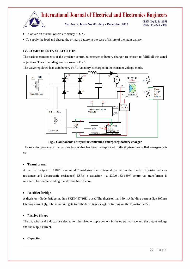
IV. COMPONENTS SELECTION
The various components of the thyristor controlled emergency battery charger are chosen to fulfill all the stated
objectives. The circuit diagram is shown in Fig.5.
The valve regulated lead acid battery (VRLA)battery is charged in the constant voltage mode.
Fig.5 Components of thyristor controlled emergency battery charger
The selection process of the various blocks that has been incorporated in the thyristor controlled emergency is
as:
Transformer
A rectified output of 110V is required.Considering the voltage drops across the diode , thyristor,inductor
resistance and electrostatic resistance( ESR) in capacitor , a 230/0-133-139V centre tap transformer is
selected.The double winding transformer has EI core.
Rectifier bridge
A thyristor –diode bridge module SKKH 57/16E is used.The thyristor has 150 mA holding current (IH) 300mA
latching current (IL).The minimum gate to cathode voltage (VAK) for turning on the thyristor is 3V.
Passive filters
The capacitor and inductor is selected to minimizethe ripple content in the output voltage and the output voltage
and the output current.
Capacitor

30 | P a g e
A 4700µF, 350V DC, Large Can Electrolytic Aluminium Capacitor is used is used to minimize the ripple
content in the output voltage.
f. Inductor
A 18mH allowing maximum permission current of 30A is used.It is of Type 43 with single core EI laminations.
The ripple content in the output after using the LC filter circuit is calcuted using equation -
Ripple factor (RF) =
RF= 1.411 % ≤ 2.5%
Output Voltage Error Detector
R1 and R2 at the output forms the potential divider circuit.The resistance values are selected as 45.3kΩ and
100Ω repectively.
The voltage across R1 is 109.75V and that across R2=0.24V if an output of 110V is obtained.
The voltage across R2 (VR2) vary in the range of 0.25V to 3.3 V as the output varies between 106V to 112V due
to fluctuations in the AC supply.The voltage VR2 is fed to AMC1100EVM , a TI device generating the error
voltage in the output and feeding it as input to the ADC as shown in Fig.6.
Fig.6 AMC1100EVM detecting the error in output voltage
DSP Processor
TMS320F28335 processor is used to generate the required gate pulses to fire the thyristor.The block diagram is
shown in Fig. 7.

31 | P a g e
Fig.7 Block diagram of TMS3220F28335
The phase angle control logic is implemented as shown in Fig.8.The thyristor firing angle gets adjusted based on
the error voltage input to the ADC.The slave ePWM signals ePWM1A and ePWM4A corresponds to the firing
angle of thyristor T1 and T2 respectively where as ePWM6A is the master ePWM controlling the generation of
ePWM1A during the positive half cycle and generation of ePWM4A during the negative half cycle.
(a)

32 | P a g e
(b)
Fig.8 Thyristor Firing Logic (a)Dead Band Generation (b) Firing angle adjustment
Firing Control Circuit
The ePWM1A and ePWM4A is fed to the firing and control circuit shown in Fig 9.The IR2121 IC limits the
inrush of huge current and shuts down the circuit in case of any fault detection.The high switching frequency
MOSFET is synchronised with the ePWM pulses.A transient voltage suppresser diode BZW50-33 and a fast
recovey diode UF4007 is used on the transformer primary for preventing the voltage from exceeding 15V .
Fig. 9 Thyristor firing circuit
The secondary of 1:1 ,15V isolation transformer is fed to the gate and the cathode of the thyristor .
Battery
The thyristor controlled emergency battery charger is used to charge nine 12V valve regulated lead acid
(VRLA) batteries connected in series.

33 | P a g e
V. SIMULATION
The simulation is carried out on MATLAB R2013a version software and the results are observed for three
different cases. The simulation circuit is shown in Fig. 10
Fig.10 Simulation Circuit
Case1. AC input to the transformer is 230V.The DC voltage and current output is shown inFig.11.
Fig.11 Output V and I for Vin=230V
Case2. AC input to the transformer is 236.9V.The DC voltage and current output is shown in Fig.12.

34 | P a g e
Fig.12 Output V and I for Vin=236.9 V
Case3. AC input to the transformer is 223.1V.The DC voltage and current output is shown in Fig.13 .
Fig.13 Output V and I for Vin=223.1 V
The simulation results are also tabulated in Table1.
Table1.Simulation Results
Thus ,the simulation results ensure proper selection of the various components as efficiency >80% and
regulation <2.5 % is achieved for input varying in the range 230±3% V.The efficiency can further be increased
by adopting ways to minimize the losses.

35 | P a g e
VI. HARDWARE IMPLEMENTATION
Cosidering all the safety precautions , the hardware circuit is set up as shown in Fig.14 .
Fig. 14 Hardware set up of the battery charger
The labels in Fig. 14 are as follows-
A - 230V AC input
B- Auto-transformer (0-230 V AC)
C-Step down transformer (230/6-0-6 V )
D-Regulated dc power supply(+12V,ground,-12V)
E-Analog to digital converter and TMS320F28335 dsp processor
F-Dual firing circuit for the thyristors
G- Semikron SKTH 56/16E thyristor - diode bridge
H-18mH inductor
I -4700uF capacitor
J- Current measuring device clamp meter
K -Multimeter
L,M-Cathode Ray Oscilloscope(CRO)
N- TI Device AMC1100EVM ,a precision isolation amplifier for error detection
O-Load (5.5Ω)
The input voltage is varied and the variation in the firing angle ,the output voltage is observed as shown in
Fig.15.

36 | P a g e
Fig.15 Gate firing pulse and dc output voltage
The hardware results showing the efficiency and regulation of the thyristor based emergency battery charger is
tabulated in Table2 and Table 3 respectiely.
Table 2. Output V,I and efficiency
Table 3. Output V,I and regulation

37 | P a g e
The output result shows that the efficiency greater than 80% is achieved with voltage regulation lesser than
2.5%.
VII. CONCLUSION
The emergency battery charger is connected in parallel to the main based battery charger as shown in the
Fig.16. The DSP controlled firing circuits is more efficient , accurate and reliable compared to the analog firing
circuit based battery charger used in the conventional bogies of trains.
Fig .16 Thyristor based emergency battery charger in parallel with the main battery charger
The DSP controller based battery charger consume lesser power and losses are also minimised to a greater
extent .

38 | P a g e
REFERENCES
[1] Don Tan, “Emerging System Applications and Technological Trends in Power Electronics :Power
electronics is increasingly cutting across traditional boundaries”. IEEE Power Electronics Magazine , Vol.
2,pp 38-47,Issue:22 June ,2015
[2] Muhammad H. Rashid , “Power Electronics :Circuit, Devices and Applications”, Pearson India,3rd
Edition,2014
[3] Arash A. Boora, FiruzZare ,Gerardand, Arindam Ghosh, “Applications of power electronics in railway
systems”, Australasian Universities Power Engineering Conference (AUPEC ),Perth, Australia, pp 1-9,9-
12 Dec 2007.
[4] J.Joosten , “Static Converter Topology(for railway applications)”, IEE Colloquium on Auxiliary
PowerSupplies for Rolling Stock, London (UK),pp 4/1- 4/4 , 22-24 Feb. 1992.
[5] Himesh Joshi and Maryam ShojaeiBaghini , “Versatile Battery Chargers for New Age Batteries”, IEEE
International Symposium on Electronic System Design(ISESD), Kochi,Kerala,India,pp279-284,19-21 Dec
2011.
[6] B. P. McGrath,D. G. Holmes,P. McGoldrick and A. Mclver , “Design of a soft switched6kW battery
charger for traction applications” , 37th IEEE Power Electronics SpecialistsConference(PESC), Jeju, South
Korea ,pp 1-7, 18-22June 2006.
[7] EnsSchmenger ,Stefan Zeltner, Reinhard Kramer ,Stefan Endres and Martin Marz, “A 3.7KW on –board
charger based on modular circuit design” 41st Annual Conference of IEEE Industrial ElectronicsSociety
(IECCON), Yokohama ,Japan, pp 001382-001387, 9-12 Nov. 2015.
[8] Martin Pittermann , Pavel Drabek and Bedrich Bednar, “High voltage converter for purpose tominimizing
of weight of traction transformer” IEEE International Conference on Applied
Electronics (ICAE), Pilsen, Czech Republic, pp 197-200,8-9 Sept ,2015.
[9] TaewonKang,BeomseokChae, Tahyun Kang and Youngsug Suh , “Design of coupled inductor forminimum
inductor current ripple in rapid traction battery charger system” ,IEEE Conference on Energy Conversion
Congress and Exposition (ECCE), Pittsburgh,USA, vol.7 ,pp 358-364, 14-18 Sept. ,2014.
[10] Francesca Palumbo, “Session 2: Tools for DSP algorithm implementation” ,IEEE Conference onDesign and
Architectures for Signal Image Processing(DASIP), Cagliari, Italy, pp 46, 08-10 Oct, 2013.