A Device to Determine When the Soles of Running...
44
A Device to Determine When the Soles of Running Shoes are Past Their Useful Life Team Members: Steven Pauls – Team Leader Brian Schwartz - BWIG Tim Rand - Communicator Brant Kochsiek - BSAC Biomedical Engineering Design 301 University of Wisconsin-Madison March 11, 2004 Advisor: Dr. Naomi Chesler Client: Dr. David Beebe Abstract Many running injuries are caused by continued use of improper or worn running shoes. The increase in incidence of injury can be directly correlated to the degradation of the 1
Transcript of A Device to Determine When the Soles of Running...
A Device to Determine When the Soles of Running Shoes are Past Their
Useful Life
Team Members:
Steven Pauls – Team LeaderBrian Schwartz - BWIG
Tim Rand - CommunicatorBrant Kochsiek - BSAC
Biomedical Engineering Design 301University of Wisconsin-Madison
March 11, 2004
Advisor: Dr. Naomi Chesler
Client: Dr. David Beebe
AbstractMany running injuries are caused by continued use of improper or worn running shoes. The increase in incidence of injury can be directly correlated to the degradation of the materials used in shoe sole construction. The degree to which a shoe sole degrades is directly related to the changing elasticity of the material. Two different methods are proposed to measure elasticity in a shoe sole. Strain gauges and FlexiForce piezoelectric force sensor devices have been added to an integrated circuit that will indirectly measure shoe sole elasticity. Once calibrated, each circuit will have a diode that lights when a shoe sole is worn past its useful life. Future testing procedures and a schedule for the completion of the project are also included in this report.
1

Design Problem
The goal of this project is to create a device that can alert runners when their
running shoes are worn beyond their useful life. The device should fit inside the sole of
the shoe without affecting the performance of that shoe, and alert runners when there
shoe soles are worn to the point where there is an increased risk of injury. Ideally the
device will directly measure the changing elasticity of the shoe sole materials over time.
However, indirect methods can be considered provided that they show correlation to the
degradation of the shoe sole materials.
Problem Motivation
It is a fact of life, eventually the pair of tennis shoes that you own will begin to
get old and wear out. For those who are not avid runners, the terms ‘get old’ and ‘wear
out’ are often associated to the appearance of a particular pair of shoes. For the avid
runner this is not always the case, as shoes that are worn past their useful life do not
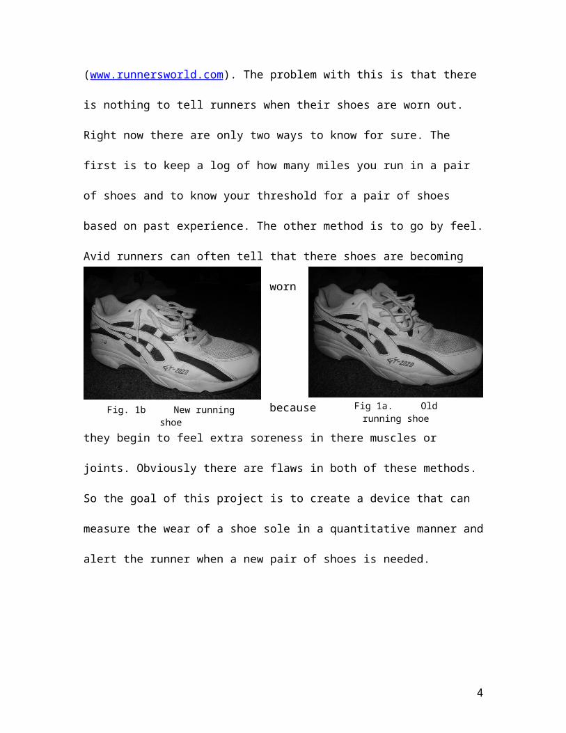
always appear worn since these shoes are only used for running. An example of this can
be seen in the pictures below (Fig. 1a, b). Figure 1a shows a running shoe that has been
worn for about 400 miles. Figure 1b shows a shoe that is new and has only been worn for
50 miles. Note that it is nearly impossible to tell the difference between the two.
It is here where the motivation for our project becomes clear. The average running
shoe lasts between 300 and 500 miles depending on factors such as the size of the person
wearing them or there running style. As a shoe is used passed this threshold, the risk for
injury of the runner can increase as much as 50 to 75 percent or even more depending on
how many miles shoes have been used for (www.runnersworld.com). The problem with
2

this is that there is nothing to tell runners when their shoes are worn out. Right now there
are only two ways to know for sure. The first is to keep a log of how many miles you run
in a pair of shoes and to know your threshold for a pair of shoes based on past
experience. The other method is to go by feel. Avid runners can often tell that there shoes
are becoming worn because they begin to feel extra soreness in there muscles or joints.
Obviously there are flaws in both of these methods. So the goal of this project is to create
a device that can measure the wear of a shoe sole in a quantitative manner and alert the
runner when a new pair of shoes is needed.
Background
Elastic Effects of Shoe Sole Material
The sole of a running shoe serves as a cushion between a runner’s foot and the
impact surface. The sole disperses the force of impact over the entire foot better than a
bare foot could do itself. Some of the force of the impact is also absorbed into the
material itself. The capacity with which the sole material effectively absorbs this impact
is called its elasticity.
The mechanics of forces on linearly elastic materials can be described by the
stress-strain equation:
3
1) = E
The stress () is usually estimated by measuring the force of impact (P, weight of the
runner or force with which the foot strikes) divided by the area (A, area of the shoe sole).
E is Young’s modulus, and the value used as the determinant for elasticity in linear
materials. is the strain a certain stress creates on a material with elasticity E, and is a
function of total depth over which deformation occurs (in this case, the thickness of the
shoe sole).
The wear and replacement of shoes is dependent on the sole material’s loss of
elasticity, as described previously. As a shoe ages elasticity E and strain decrease,
whereas the other variables (P and A) do not. The maximum forces a sole material can
ideally absorb are described by a variation of eqn. (1):
2) P = A E
Thus as elasticity E decreases, so do the total forces the sole absorbs.
Extra forces experienced during impact are transmitted through the runner’s foot
and leg; these are the adverse effects avoided via replacing worn shoes. As shoes age and
elasticity decreases, the runner experiences increasingly larger internal stresses. These
stresses can lead to injuries such as fractures and strains in the bones and joints of the
runner.
Running
Most runners start a stride by striking the ground on the outside of the heel, then
the rest of the foot comes down rolling slightly inward, and as the heel lifts the runner
pushes off of the forefoot. The rolling action of the foot from the heel to the ball and toes
is termed pronation and differs in the various running strides based on the individual
4
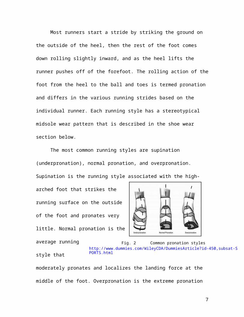
Fig. 2 Common pronation styleshttp://www.dummies.com/WileyCDA/DummiesArticle?id-450,subsat-SPORTS.html
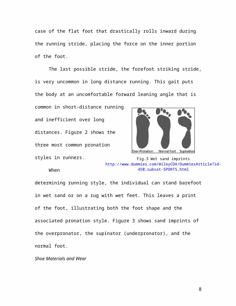
Fig.3 Wet sand imprintshttp://www.dummies.com/WileyCDA/DummiesArticle?id-450,subsat-SPORTS.html
runner. Each running style has a stereotypical midsole wear pattern that is described in
the shoe wear section below.
The most common running styles are supination (underpronation), normal
pronation, and overpronation. Supination is the running style associated with the high-
arched foot that strikes the running surface on the outside of the foot and pronates very
little. Normal pronation is the average running
style that moderately pronates and localizes
the landing force at the middle of the foot.
Overpronation is the extreme pronation case
of the flat foot that drastically rolls inward
during the running
stride, placing the force
on the inner portion of the foot.
The last possible stride, the forefoot striking stride, is very uncommon in long
distance running. This gait puts the body at an uncomfortable forward leaning angle that
is common in short-distance running and inefficient over long distances. Figure 2 shows
the three most common pronation styles in runners.
When determining running style, the
individual can stand barefoot in wet sand or on a
rug with wet feet. This leaves a print of the foot,
illustrating both the foot shape and the associated
pronation style. Figure 3
5

Fig. 4 Components of a running shoehttp://www.dummies.com/WileyCDA/DummiesArticle?id-450,subsat-SPORTS.html
shows sand imprints of the overpronator, the supinator (underpronator), and the normal
foot.
Shoe Materials and Wear
The running shoe is composed of four elements: the uppers, the midsole, the
footbridge (arch as it has been termed), and the outsole. The uppers are typically made
from leather, nylon, or vinyl depending on the quality of the shoe and its uses. The
footbridge is made from a plastic or foam material, and the outsole is made of rubber.
The layout of a running shoe and its components can be seen in Figure 4. The midsole is
the portion of the shoe that we will be focusing on when we are testing wear, because the
midsole materials lose elasticity without affecting the rest of the shoe. Typically the
midsoles are made from a combination of Ethylene and Vinyl Acetate (EVA) and
Polyurethane (PU) polymers. When force is exerted on these polymers, there is a
reduction of the air content in the foam cells, and after enduring a long run the foamed
copolymer does not appear to fully recover. With loss of air content, the midsoles begin
breaking down structurally causing unwanted stresses in the joints of the runner,
especially the knee.
6
MidsoleUpper
FootbridgeOutsole
Forefoot striking Overpronation Neutral Supination
Fig. 5 Midsole wear patternshttp://www.fleetfeethouston.com/tips/basics.asp
The midsoles wear according to the striking pattern of the runner. The forefoot
striker is more often a short-distance runner, but about five percent of the running
population has adapted this style for long distance. This runner will wear the midsole
directly under the ball of the foot first. The overpronator severely rolls their foot over
when striding, causing a wear localized over the inside portion of the ball of the foot and
at the back of the heel where the foot first contacts the running surface. The neutral
striking runner will wear out the midsole under the ball of the foot like the forefoot
striker, but in addition they will wear out the heel region like the overpronator. The last
wear pattern occurs in the supinator who pronates very little. Typically this runner will
wear the outside portion of the midsole of the forefoot and the heel respectively. Figure 5
is a series of diagrams depicting the four different wear patterns seen in running shoes.
Pressures of Running
The main wear points of the shoe occur wear the foot exerts the most pressure.
As the foot makes the first impact with ground there is a spike in pressure at the shoe
heel. When the foot pronates forward and pushes off, the ball of the foot and the big toe
experience similar spikes in pressure. The position of the pressure at the ball of the foot
depends upon the specific striking pattern of the runner: the neutral runner experiences
this pressure at the middle to inner portion of the ball of the foot; the supinator
7
experiences this pressure at the middle to outer portion of the ball of the foot; and the
overpronator experiences this pressure at the inside portion of the ball of the foot. A
depiction of these relative forces during running can be seen in Figure 6.
`The force generated by the foot during running is roughly three times the weight
of the runner. Pressure can be calculated using the equation Pressure = Force / Area.
Based on this relationship, we can come up with more accurate values for the pressures
exerted by runners of varying weights, and thus determine the necessary strength
specifications for our sensors, as long as we can determine appropriate area values.
Design Constraints
After meeting with our client, Professor David Beebe, a list of design constraints
was created. First of all, the device needs to be lightweight so it does not affect the
performance of the shoe. The device should also fit into the shoe sole without causing the
runner any discomfort. Ideally, the runner will not know the device is present until the
sensor goes off telling them that a new pair of shoes is needed. Even more important then
these two constraints is the fact that the device must last the life of the shoe. This is
clearly important since we are trying to measure wear at the end of the shoes useful life.
8

To add to this, any wiring or circuitry must be able to stand up to the force that is exerted
on the sole during normal running. Next, the device must have a clear indicator to
indicate when the shoe is worn out that can be understood by a runner that might not
under stand the theory behind the device. The last constraint is that our prototype should
be as cost effective as possible, so as to allow for possible mass production in the shoe
market.
Another factor that we may consider in the later phases of our design project is
the many different combinations that are used to make running shoe soles. It certainly
would be ideal if the device would be compatible with as many different varieties of
materials as possible. This constraint, however, is secondary to the many mentioned
above.
Literature Search
We searched the internet and “The Lore of Running” book written by Tim Noakes
MD to see if any work has been done on an indicator of shoe wear that is related to shoe
sole elasticity. Group members also tried to contact employees within Nike and Reebok
to see if either of those companies had done any research on this topic. However, no
useful information relating to this project was found. We also ran a patent search for a
shoe wear indicating device but yet again nothing was found.
A couple professors suggested that we research the LA Gear Light shoes so we
searched the internet for information on exactly how the lights in the shoes worked.
These shoes have a light in the heel of the shoe and would light up after each step. They
were mostly worn by children and teenagers in the early 1990s. The LA Gear website
(www.LAGear.com) yielded no information about the light shoes. We also emailed the
9
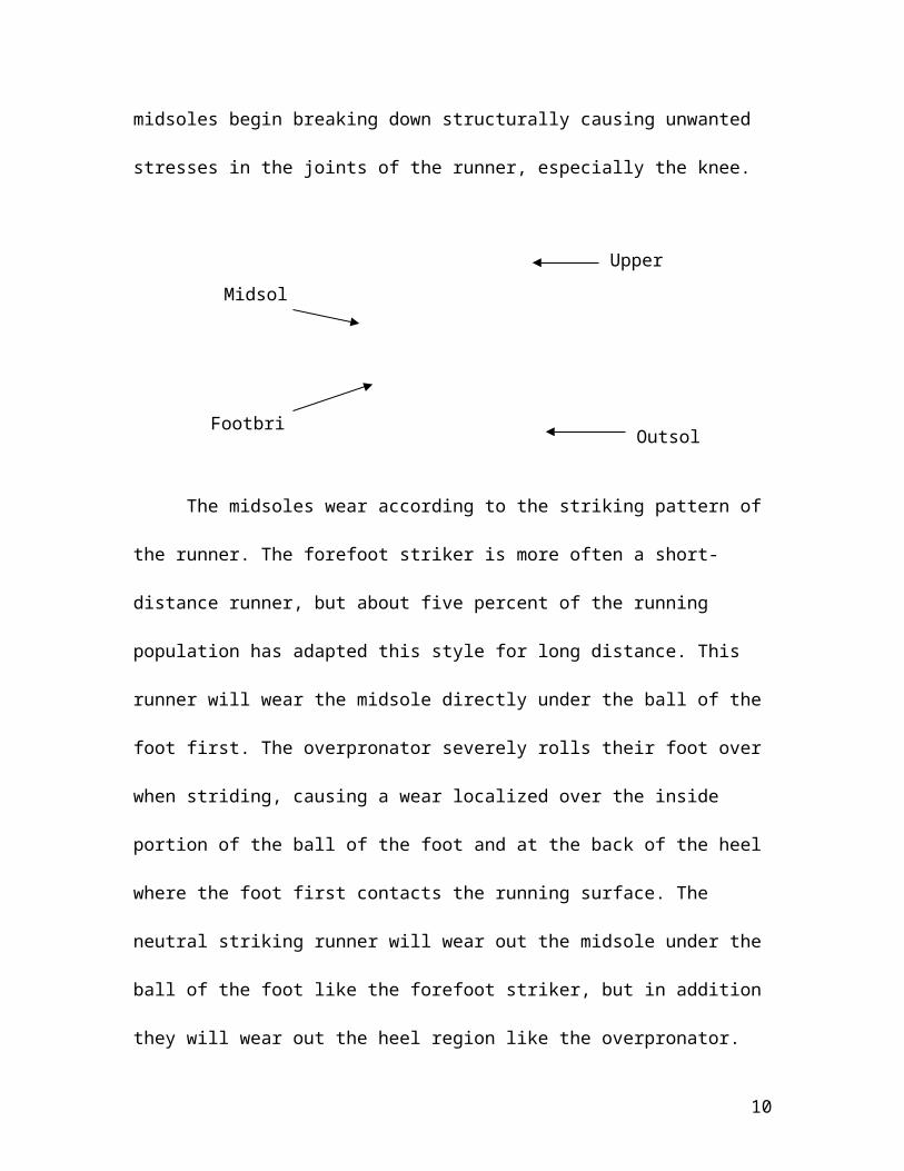
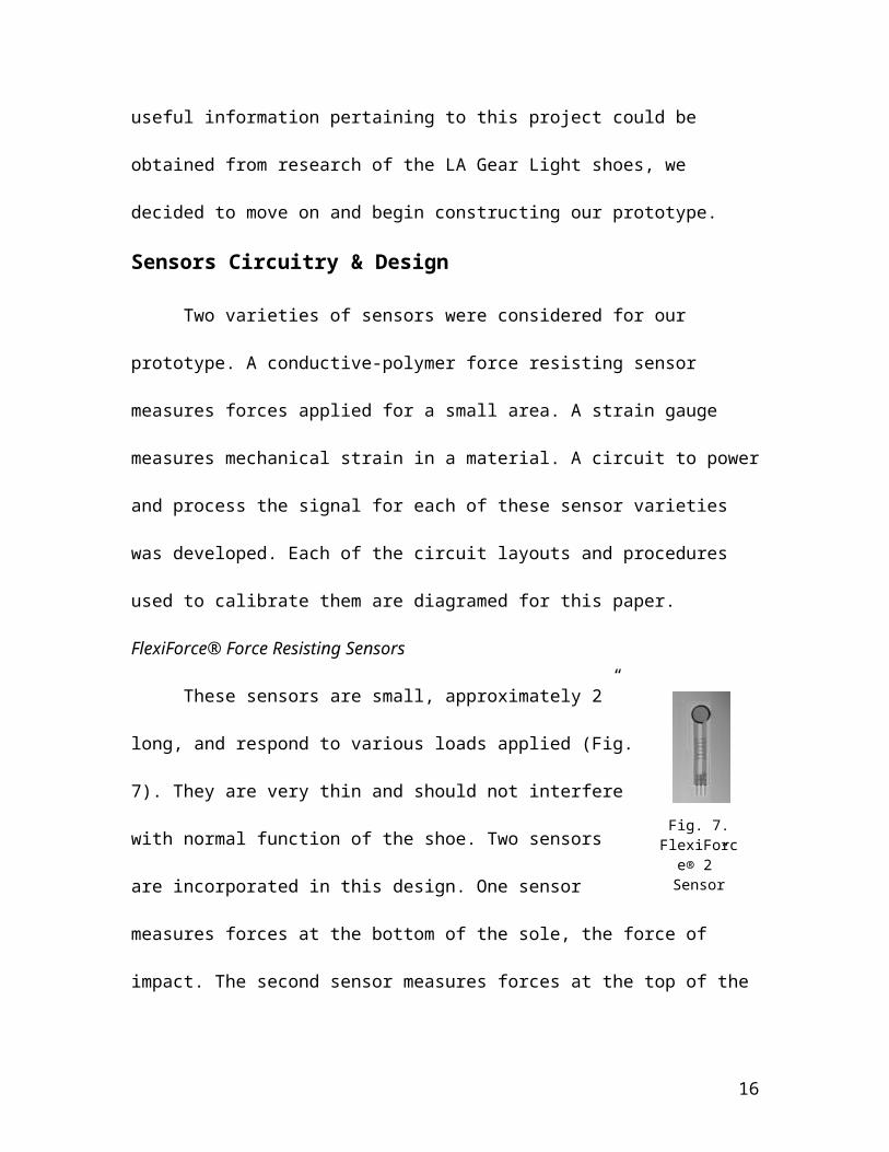
Fig. 7. FlexiForce®
2” Sensor
company to get some information on the shoe but the company declined to disclose any
information on the device or how it worked. Further online searching led us to a website
with a vast amount of information on all types of shoes
(http://sneakers.pair.com/index.html). This site mentioned that the shoe contained an
interchangeable and replaceable light-emitting diode module. It also contained a battery
which was replaceable. According the webmaster of the website, the force from each step
taken somehow closes a circuit which allows the battery to supply the light emitting
diode with a current causing it to light up. The webmaster suggested running a patent
search at www.uspto.gov to find more detailed information on the shoes. Our group
searched the patent office extensively however no patent relating to the LA Gear Light
shoe could be found. Since no useful information pertaining to this project could be
obtained from research of the LA Gear Light shoes, we decided to move on and begin
constructing our prototype.
Sensors Circuitry & Design
Two varieties of sensors were considered for our prototype. A conductive-
polymer force resisting sensor measures forces applied for a small area. A strain gauge
measures mechanical strain in a material. A circuit to power and process the signal for
each of these sensor varieties was developed. Each of the circuit layouts and procedures
used to calibrate them are diagramed for this paper.
FlexiForce® Force Resisting Sensors
These sensors are small, approximately 2” long, and respond to
various loads applied (Fig. 7). They are very thin and should not interfere
with normal function of the shoe. Two sensors are incorporated in this
10
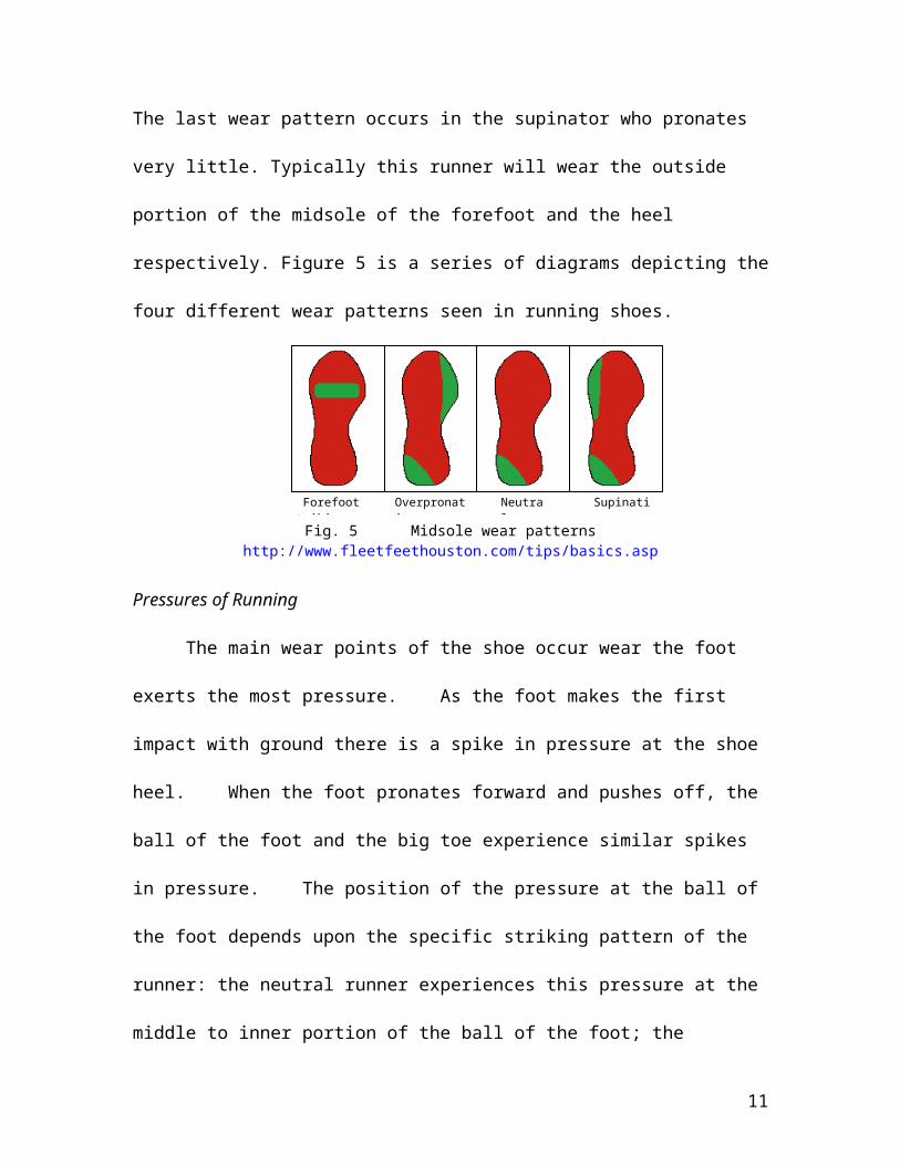
Fig. 8 Force Sensor
design. One sensor measures forces at the bottom of the sole, the force of impact. The
second sensor measures forces at the top of the sole, the force experienced by the runner
and subsequently absorbed.
The circuit design (Fig. 8) diagrams the stages necessary to process and interpret
the sensor signal. The sensors act as resistors whose resistance varies inversely to the
load applied. The value range listed with the sensors technical specifications
(http://www.tekscan.com/flexiforce/flexiforce.html) is 5 MΩ – 5 kΩ. The higher
resistance corresponds to the sensors un-loaded value.
The sensor selected is sensitive
to values from 10-100 lbs. Larger loads
can be accurately measured by lowering
the driving voltage. The first stage of the
circuit for each sensor consists of the full
driving voltage applied over a 100 kΩ
potentiometer and run through a unity
amplifier. Another way to detect larger
loads is to lower the resistance and thus
the gain in the second stage, the
inverting amplifier. A 20 kΩ
potentiometer is used to modulate this
resistance from 1kΩ to 21 kΩ.
These two features force less
current through the sensor and lower the
11
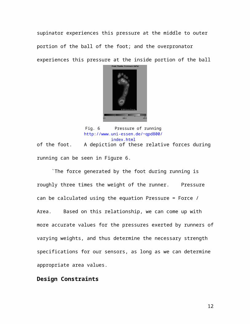
Fig. 9 Strain Gauge
load-voltage response after the inverting amplifier; the sensor output. Larger loads will
not cause the inverting amplifier to saturate. Exact values for both potentiometers will be
determined during calibration of the circuit for the prototype.
The first two stages of the circuit are identical for each sensor. They should have
identical load-voltage responses. This is essential for the third stage, the differential
amplifier. The purpose of this stage is the integration of the two signals.
The differential amplifier will produce a signal equal to a proportion of the two
sensors magnified by the amplifier gain. The specific value of this gain needs to be
determined to create a viable voltage response and take into account Common Mode
Rejection Ratio (CMRR).
The ‘failure’ value will be determined at output of the differential amplifier. This
value corresponds to the ratio between the two sensors which demonstrates shoe wear.
The specific magnitude of this value will be determined during the repetitive load testing.
This value will be the reference voltage for a comparator amplifier, the final stage of the
circuit. The comparator currently operates a Light Emitting Diode (LED) depending on
whether or not the shoe is ‘worn’. This output will be refined for the final design.
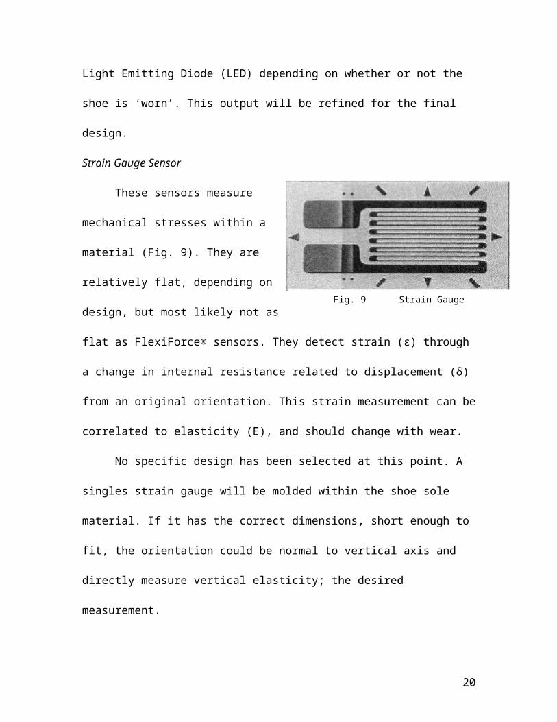
Strain Gauge Sensor
These sensors measure mechanical
stresses within a material (Fig. 9). They are
relatively flat, depending on design, but
most likely not as flat as FlexiForce®
sensors. They detect strain (ε) through a
change in internal resistance related to
12

Fig. 10 Strain Guage
displacement (δ) from an original orientation. This strain measurement can be correlated
to elasticity (E), and should change with wear.
No specific design has been selected at this point. A singles strain gauge will be
molded within the shoe sole material. If it has the correct dimensions, short enough to fit,
the orientation could be normal to vertical axis and directly measure vertical elasticity;
the desired measurement.
Should a long, flat strain gauge be the only viable alternative, however, it will
need to be inserted laterally along the plane of the shoe. Strain measured in this
orientation can still be correlated to changes in E in the vertical axis, but are modulated
by the Poisson’s ratio (v) of the material. v for our material is ≈ .3. This reduction in
signal amplitude will require increased sensitivity in the processing circuit.
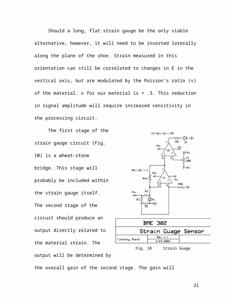
The first stage of the strain gauge
circuit (Fig. 10) is a wheat-stone bridge.
This stage will probably be included
within the strain gauge itself. The second
stage of the circuit should produce an
output directly related to the material
strain. The output will be determined by
the overall gain of the second stage. The
gain will correspond to the amplifier
resistor divided by one-half the stain-
gauge impedance.
13
The third stage of this circuit is a comparator identical to the force sensor circuit.
A reference voltage which corresponds to the output signal in a ‘worn’ shoe will be
compared to the strain-gauge signal. The LED output will also be refined for the final
prototype.
Embedding of Sensors Into Polymer For Testing
After the circuits were built and tested, a prototype shoe sole with the desired
sensors embedded inside was created using liquid silicone and an injection molding
machine. Group members consulted with Professor Tim Osswald and his graduate
student Amelia Cosgrove for assistance in forming the shoe sole. Silicone was chosen as
the polymer for preliminary testing because it has properties somewhat similar to
polyurethane and was easy and inexpensive to acquire. Following the preliminary testing
it is probable that polyurethane and other materials that match those currently used to
make shoe soles will be used to mold prototypes.
Prior to the embedding of the sensors, Wires (24 guage) were soldered to each
lead on the FlexiForce® sensors. The sensors were laid in the mold at the top and bottom
of the uncured silicone. The liquid silicone was then cured at a temperature of 160
degrees. This temperature was chosen because it is below the highest temperature at
which the FlexiForce® sensors can function properly. Finally, a running shoe sole was
traced onto the mold, and a scissors was used to cut out the shape and the wires were
pulled from the silicone (Fig.11)
14

Sensor response Test
0
1
2
3
4
5
6
0 200 400 600 800 1000
Load (lbs)
Volta
ge (V
)
Tested
Projected
Figure 12: Voltage output of force sensor prototype vs. Load Applied
Fig. 11 Breadboard with circuit for both prototypes (left) and Flexiforce® sensors in a silicone mold (right)
Although a prototype for the strain gauge option has not yet been molded, the
construction of this prototype will use the same methods described in the molding of the
FlexiForce® sensor prototype. However, we will only be inserting one strain gauge into
the mold as opposed to the two in the other prototype.
Current Standing
As of the week of April 30, 2004 our group has just completed the initial testing
on the force sensor prototype. The prototype consists of two FlexiForce® force sensors
integrated into a polymer mold made of silicone (Figure 11). The silicone mold was
15
formed in Polymer Testing Lab in Mechanical Engineering . With the help of John
Dreger in the Materials Testing Laboratory in Engineering Hall Rm. 1313, we applied
constant static loads between 0 an 450 lbs (9 loads at 50 lbs. integrals) to our prototype
and then read the output of our circuit. Above (Fig. 12) are the voltage outputs of the
circuit we recorded with respect to the load applied to the prototype.
The black line on the graph represents the data we recorded from the testing and
the red line represents the relationship we expected to get based upon the information and
the equations found on the website of the manufacturer of the force sensors
(www.tekscan.com/flexiforce/flexiforce.html). The output voltage of our circuit barely
changed at all when the different loads were applied to the prototype. This led us to
believe that there is an error in our circuit. Another possible cause for these poor results is
that somehow the injection molding damaged the FlexiForce® force resisting sensors.
This could be due to high temperatures or possibly air bubbles within the silicone mold.
We hope this is not the case because the force sensors currently embedded in the
prototype would be worthless. This would be a major disappointment considering they
are rather expensive ($16.25 a piece).
Future Work
Early this summer we need to acquire a strain gauge and then mold it into
silicone. We then plan to apply loads of 0 to 450 lbs. (integrals of 50 lbs.) just as we did
with the force sensors. Also, early this summer or late this semester we must figure out
what exactly is wrong with the force sensor prototype. We plan to first go through and
rework the corresponding circuitry to determine if that is the problem. If testing reveals
that the circuitry is in working order, then we must determine what is wrong with the
16
force sensor prototype itself. We will probably have to contact the manufacturer Tekscan
and figure out if the injection molding process could have somehow damaged the sensors.
If this is the case, then we will have to design a new way to embed the sensors in a
polymer mold or find completely new sensors that will work with the injection molding
process that is available for us to use.
Once we have preliminary tests done on both prototypes to show that they are
both working properly we will then test both prototypes to simulate 500 miles of running
wear. The machine we use to test them is the MTS Dynamic Fatigue Testing System
(Fig. 13) which can be found in the Materials Testing Lab in Engineering Hall. We spoke
with John Dreger the last week of April and he agreed to train our group early next fall on
how to use the machine so we could do the extensive testing on our own. It was brought
to our attention at the later on that week that he may be retiring which could pose a
problem. If this is the case then we will have to contact his replacement this summer to
see if he or she can help us out. Details about the machine and the exact testing procedure
we plan to use can be found in the “Proposed Future Testing Procedure” section below.
Once testing is done on both prototypes to simulate running wear we plan to
analyze all of the necessary data to determine which device is a better indicator of
elasticity. We will also need to determine a value for the output of the device which will
represent that the shoe sole is sufficiently worn out. Next we will need to determine
exactly where in the shoe sole we plan to place the chosen device. By this time we will
have hopefully undergone all of the necessary human subject testing procedures so we
will be ready to begin human testing of our prototype shoe. Human testing of the
prototype shoe will most likely take a lot of time since the subject will have to run
17

Fig. 13: A newer version of the MTS dynamic fatigue testing system that will be used for our testing.http://www.mts.com/menusystem.asp?DataSource=0&NodeID=1483
somewhere between 300 and 500 miles before the shoe is worn out. So therefore, we
hope to find someone who runs an awful lot in order to keep the project from coming to a
halt mid-semester. If everything works to plan, once human testing of the shoe prototype
is complete we will be ready to submit a patent application. If not, then we will have to
figure out what went wrong and find ways to improve upon our design. If we have extra
time on our hands at the end of the semester, our group could possibly figure what would
needs to be done for our design to get FDA approval (or any other government agency’s
consent) for commercial use. A detailed week by week description of what we plan to
accomplish next semester can be found in Appendix B. In addition, a proposed budget for
next semester can be found in Appendix C as well.
Proposed Future Testing Procedure
Having completed both the breadboard circuit and the prototype shoe soles, a
major goal as we continue this project will be to gather very data that corresponds the
elasticity of our test material to changing outputs of our circuits. A plan for future testing
has been set up for next semester.
Data has been gathered from group members running habits. It has been
determined that about 4000 steps per shoe is a good estimate of a 5 mile run. This along
with the anticipated loads of a wide variety of weights of runners will be used to set up
the procedure.
18
Group members have met with John Dreger, the supervisor of the material testing
laboratories in room 1313 of Engineering Hall. Group members plan to get trained on an
MTS 1000 Hertz dynamic fatigue testing machine (Fig.13) that can simulate the process
of running on our prototype. The machine will be run at a frequency of about .5 Hertz at a
constant load that is within the range of impacts anticipated (see Background
Information) These loads could range between about 300 to 600 pounds. A single load
value will be used for each molded prototype. A wide variety of loads on different
prototypes must be used to make sure that our circuit set up is responsive to varying
weights of runners.
Our prototype will be placed in the machine and the desired load will be applied
4000 times to simulate a 5 mile run. At the end of the simulation a static load will be
applied and the circuit output voltage will be read. The polymer’s elasticity will then be
measured and points will be plotted on a voltage output vs. elasticity curve. This process
will be repeated 100 times in order to simulate wear of approximately 500 miles. This
process will be repeated for each of our prototype options (FlexiForce® sensors and
strain gauges).
Material testing will be used to calibrate the circuits. The force sensors need to be
calibrated for sensitivity on loads up to 600 lbs. Gain in the differential amplifier needs to
produce a viable signal with good CMRR. A strain-gauge design needs to be selected. A
circuit with proper sensitivity needs to be calibrated if v is to be used in signal
processing. A more user-friendly output needs to be designed and incorporated. For a
final prototype, the selected design needs to be assembled on a printed circuit board.
Ethics Discussion
19
The ethical considerations meeting placed us in the human subjects testing group.
This group discussed the specific steps to be followed as we approach a prototype design.
The discussion focused on the safety and rights of the test subject. In our project, we
intend to create a shoe with imbedded strain gauges and/or force sensors, which will have
little affect on the test subject.
We are not trying to create a new product, we are just adding on to the running
shoe. Our testing steps are less severe than other groups’. The only risks are in
malfunction of the sensors themselves. This is highly unlikely, however, as they will be
molded into the sole. We envision our project as being very safe for the subject, so long
as they do not have any conditions that prevent them from running.
Appendix A
20
PDS: v. 2
Date: May, 2004
Title: Shoe Elasticity Measurement Device
Group Members:
Steven Pauls
Brian Schwartz
Brant Kochsiek
Tim Rand
Problem Statement: It has been determined that as the soles of running shoes degrade,
the incidence of injury for runners rises. Our goal is to develop a device that could be
placed in a shoe sole that would indicate when a pair of running shoes is worn out to the
point where injuries could develop.
Client Requirements:
Device:- Should measure shoe sole elasticity either directly or indirectly
- Should not interfere with comfort of the shoe
- Must be light weight
- Should hold up throughout normal life of running shoes (i.e. 300-500 miles)
- Must have clear indicator so a runner will know when shoe is worn
Indicator:
- Should be able to be read and understood by average runner
1. Physical and Operational Characteristics
a. Performance requirements; The device must be able to measure the elasticity of a shoe sole for at least 5 years. It does not necessarily have to measure elasticity while the user is running or walking but rather it must take a measurement at some point when it is not being used. The device should take an elasticity measurement at least once a week. The device should be able to withstand the force of a 220 lb. runner using the shoes daily, which is roughly three times the body weight (660 lb).
21
b. Safety; There should be no chance of the device electrically shocking the runner in anyway. Most importantly, the sensor in the shoe sole should be implanted in such a way that there is no risk of it puncturing the runner’s foot.
c. Accuracy and Reliability; The device needs to indicate to the user when the elasticity of the shoe sole has sufficiently worn out and the risk of injury is significant. The value of elasticity for when the shoe sole is worn out is unknown, but current methods say this occurs around 300 miles of running. This value will be determined through research and testing. The sensor must be accurate to within five Pa of this unknown elasticity value. The sensing device must be reliable as to not signal at an inappropriate time when the set elasticity value hasn’t yet been reached.
d. Life in Service; The device should take at least one elasticity measurement per week for at least 3 years during service. Ideally the sensor would last a few months longer then when the shoe sole reaches its elasticity threshold and is completely worn out. That elasticity value should be reached when the runner has run around 300 miles. Depending on how often and how far the user runs, the sensor would go off anywhere from a month to a few years.
e. Shelf life; The shelf life of the shoe before it is bought should be a year maximum. Anything over that could put too much use on the battery if it is taking measurements of elasticity at least once a week. A way to eliminate the battery use during shelf life would be to have a worker turn on the sensor once the shoe is purchased. Since consumers are likely to be avid runners, the shoe is unlikely to sit in his/her closet for a long period of time.
f. Operating Environment; The device must be able to withstand temperatures from 0 to 100 degrees Fahrenheit. It should be able to withstand the humidity generated by the feet during running. The device must also be able to withstand a great amount of pressure. Further research and testing must be done to determine this value, but the relationship is Pressure = Force / Area, with force roughly equal to three times the body weight.
g. Ergonomics; A very important aspect for this product is ergonomics. The product should work within an existing shoe sole. The product should not alter existing ergonomic qualities in the shoe sole in ways that would affect performance.
h. Size; Product must conform to dimensions of an existing shoe sole. Depending on the final form of the product, this could involve shoe sole forming with these specific dimensions in mind. Access for repair could be necessary, also, depending on final design.
i. Weight; Product weight will not cause an undue or noticeable addition to an already lightweight shoe. Depending on how far the project progresses, refinement of the product could yield designs of lesser weight, but these could prove unnecessary depending on shoe function.
22

j. Materials; No particular materials are required for this product, but the typical shoe sole is made from polyurethane and ethylene and vinyl acetate. Materials that easily deform under high moment impacts or high force impulses should be avoided, because they could wear inappropriately.
k. Aesthetics; Depending on final product design, aesthetic appeal could be required. If the design is incorporated into the outward appearance of the shoe, or somehow affects it, these factors should be taken into account for overall visual appeal.
2. Production Characteristics
a. Quantity; Relatively few units needed for testing/prototype stage. Final product stage would need to be produced on a scale similar to that of the shoes the unit would be used in. High necessary quantities of final product form.
b. Target Product Cost; Cost should be a fraction cost compared to overall shoe manufacture cost. Depending on sources, this cost could be $5-$20. The final product would ideally cost no more than $1-$5.
3. Miscellaneous
a. Standards and Specifications; Product must meet standards for comfort and performance set forth by runners.
b. Customer; The customer for this product ranges from the most avid of runners to the recreational runner.
c. Patient-related concerns; Varying customer weights should not affect performance of our product.
d. Competition; Toothbrush and shaving companies have experimented with a variety of wear indications, but as of yet no shoe company has a method to detect shoe wear built into any of their shoes.
e. Ethics; Human subject testing will need to be conducted on the prototype shoe sole, so it is important to follow ethics and avoid testing that could have negative impact on the test subject.
Appendix B
23

Current Budget:
4 FlexiForce Force Sensors: $80Total cost this semester: $80
Proposed Budget:
Strain Gauges: $10Two Pairs of Tennis Shoes: $1004 FlexiForce Force Sensors: $80Printed circuit board (3 copies): $80Printed circuit board components: $10Total cost for next semester: $300
Total predicted cost for entire project: $380
Appendix C
Tentative Schedule for the Shoe Elasticity BME 400 Design Team Fall 2004
24

*Note- This is just a tentative schedule. We would like to begin human testing of the prototype shoe as soon as possible since this will require a fair amount of time.
Last Week of Spring 2004 Semester and the Summer-Acquire strain gauge, mold into polymer, and apply 5 known loads to test the correlation
of the output of the device to the force applied-Find someone who has experience using the load applying machine found in
Engineering Hall room 1313. We will ask Prof. Darrel Thelen, Prof. Heidi Ploeg, and Prof. Frank Fronsak if any of their graduate students have knowledge in this field and if they would be willing to help us out in the fall. Another option is to find a senior Mechanical Engineering that we know and see if he or she would be willing to help us out with testing. Our last option is to see if John Dreger (director of the Materials Science lab in 1313 Engr. Hall) would be willing to help us out or train us on how to use the machine
-John Dreger said he would be willing to train us early next fall, however, it has come to our attention that he may be retiring. We will need to figure this out over the summer.Week of September 3rd
-Regroup and make sure all of the goals set for the summer were accomplished.-Prepare the two prototypes and corresponding circuits for extensive testing which will
simulate approximately 500 miles of running wear-Read over and agree on the testing procedures that we decided on from the previous
semester
Week of September 10th
-Begin testing on each prototype
Week of September 17th
-Continue testing on each prototype and hopefully get all of the necessary data -If testing is complete organize and analyze the data-Determine where to place the circuit, indicator device (most likely a light-emitting
diode), and strain gauge (or force sensors) in the shoe -Determine if the circuit and light-emitting diode should be permanently attached or
detachableWeek of September 24th
-Determine which device (force sensors or strain gauge) has the best correlation to elasticity and is best suited to be placed in a shoe sole (size, reliability, etc.)
-Determine exactly what value is a good measure of sufficient shoe wear (300-450 miles)-Double check that the necessary circuit will function as desiredResearch ways and talk to professors about decreasing the size and weight of the needed circuit
Week of October 1st
-Investigate ways we could integrate the chosen sensor into a shoe sole
25

-If it is not possible to do this ourselves, we should research and contact companies that could do this for us
-Either way we should get the sensor into the shoe sole ASAP since testing of the shoe soles will require lots of running (i.e.-time)
Week of October 8th
-Research and discuss what human subject testing procedures/applications etc. we will need to complete
-Determine if we need approval from the FDA or any other government agency to begin testing
-Decide on whether we will test out the shoe sole (with the elasticity measuring device) ourselves or have other people run with the shoes (i.e.-people that we know that run avidly) (aka Steve’s friend Dale)
-Either way whoever tests the device should run at least 20-25 miles per week so we can get the needed results ASAP-Maybe have multiple people use the same shoe in order to get the maximum mileage in the shortest amount of time
Week of October 15th
-Prepare for the mid-semester presentation.-Prepare the mid-semester report.-Begin human testing of the prototype shoe
Week of October 22nd
-Continue human testing of prototype shoe-Address and fix any problems with the prototype shoe-Possibly brainstorm ways to improve our design
Week of October 29th
-Continue human testing of prototype shoe-Discuss with advisor/client/other professors whether our design is patentable or not-If so then begin the patent application process-Continue to research ways to improve the design
Week of November 5th
-Continue human testing of prototype shoe-Finish any work needed for the patent application-Continue to research ways to improve the design
Week of November 12th
-Continue human testing of prototype shoe-Continue to research ways to improve the design
Week of November 19th
-Hopefully by now the prototype shoe will be sufficiently worn and the indicator light will go off as desired
26
-Analyze the results of the human testing and hopefully determine that the design was a success
-If not discuss what went wrong and what improvements/changes should be made
Week of November 26th
-Continue to brainstorm, research, and discuss ways that could improve our design-If design was success determine what needs to be done for it to receive FDA (or any other governmental agency) approval for commercial use-?
Week of December 3rd
-Finish up any odds and ends-?
Week of December 10th
-Prepare for the Fall 2004 final presentation-Begin work on the Fall 2004 final report-Determine if this project should be continued for another semester
Week of December 17th
-Complete final report and make sure our design notebooks are in order-Finish any other work on this project that needs to be completed
Appendix D
References
27

“1000 Hz High-Cycle Fatigue Testing Systems.” MTS Inc. Accessed 4/28/04 URL: http://www.mts.com/menusystem.asp?DataSource=0&NodeID=1483
“Anatomy of a Running Shoe.” American Running Association. Accessed: 04/26/04 URL: http://www.americanrunning.org/displayindustryarticle.com.
“Biomechanics Laboratory.” Accessed: 04/24/04 URL: http://www.uni- essen.de/~qpd800/index.html.
“BTopenworld”. Accessed: 04/24/04 URL: http://www.btinternet.com/~bury_rd/cheatah.jpg.
“FlexiForce Force Sensors.” Tekscan. Accessed: 04/25/04 URL: http://www.tekscan.com/flexiforce/flexiforce.html.
Hennig, E. M., & Milani, T. L. 1995. In-shoe Pressure Distribution for Running in Various Types of Footwear. Human Kinetics Publishers Inc., New York.
Mills, N., & Verdejo, R. 2002. Performance of EVA Foam in Running Shoes. Blackwell Inc., UK, Birmingham.
“Runner’s World.” Runners World. Accessed:04/27/04 URL: http://www.runnersworld.com/.
“Running Shoes.” ePodiatry. Accessed: 04/26/04 URL: http://www.epodiatry.com/running-shoes.htm,
28