A Design Study in Steel Castings Rotor Disc Casting for ... · PDF fileProject funding was...
26
A Design Study in Steel Castings Rotor Disc Casting for the Traction Motor in a Diesel Locomotive Design Study Outline Introduction Design for Performance Alloy Selection Design for Production Mold Method Orientation Rigging System -- Gates and Risers Machining and Quality Assurance Lessons Learned and Summary Start the Design Study ! Next Acknowledgment -- The metalcasting design studies are a joint effort of the Steel Founders' Society of America and the American Foundry Society. Project funding was provided by the American Metalcasting Consortium Project, which is sponsored by the Defense Logistics Agency, Attn: DLSC-T, Ft. Belvoir, VA, 22060-6221 Return to SFSA Home Page Copyright 2003 by the Steel Founders' Society of America. All rights reserved. Address comments to: [email protected] Last Modified:July, 2003 by STG In cooperation with Huron Casting
Transcript of A Design Study in Steel Castings Rotor Disc Casting for ... · PDF fileProject funding was...

A Design Study in Steel Castings
Rotor Disc Casting for theTraction Motor in a Diesel Locomotive
Design Study OutlineIntroductionDesign for Performance Alloy SelectionDesign for Production Mold Method Orientation Rigging System -- Gates and RisersMachining and Quality AssuranceLessons Learned and Summary
Start the Design Study ! Next
Acknowledgment -- The metalcasting design studies are a joint effort of the
Steel Founders' Society of America and the American Foundry Society.Project funding was provided by the American Metalcasting Consortium Project, which
is sponsored by the Defense Logistics Agency, Attn: DLSC-T, Ft. Belvoir, VA, 22060-6221
Returnto SFSA
Home Page
Copyright 2003 by the Steel Founders' Society of America. All rights reserved. Address comments to: [email protected] Modified:July, 2003 by STG
In cooperation withHuron Casting

An Example in Steel Casting Traction Motor Rotor Disc
Traction Motor - Application● A diesel locomotive is equipped with a turbocharged diesel engine that
delivers shaft horsepower to the main electrical generator for conversion to electrical power to drive the locomotive.
● The electrical power from the generator is then distributed to the traction motors, each of which converts the electrical energy into torque on the drive wheels through a reduction gear case.
Back Next 2
Returnto SFSAHome Page
Copyright 2003 by the Steel Founders' Society of America All rights reserved. Address comments to: [email protected] Modified :July, 2003 by STG
Page 1
In cooperation withHuron Casting

An Example in Steel Casting Traction Motor Rotor Disc
Coil Rotor FunctionAn integral part of each traction motor is the armature coil rotor with the extensive electrical windings which
develop the rotating field in the motor.
● The armature coil rotor has a complex shape disc on one end of the rotor shaft which serves as an end plate, containing the windings and acting as a structural feature.
● The main shaft is friction welded on the inside face of the disc; a smaller pinion shaft is press fit into the outer face of the disc.
Back Next 3
Returnto SFSAHome Page
Copyright 2003 by the Steel Founders' Society of America All rights reserved. Address comments to: [email protected] Modified :June, 2003 by STG
Page 1
In cooperation withHuron Casting

An Example in Steel Casting Traction Motor Rotor Disc
Coil Rotor Disc Casting -- Description
The coil rotor disc is the most complex casting in the rotor assembly.
● The 15" diameter disc has a weight of 120 pounds.
● The disc has a slotted and ribbed main body and a 5.7" high, 7" diameter center hub with a 4.7" ID center hole.
● The outer rim is 3" high and 0.5" thick. ● The slots in the disc aid in cooling of the
windings. ● The disc has a range of section thicknesses -
from 1.9" to as thin as 0.19" in the ribs.
Huron Casting produces approximately 2000 of these steel disc castings every year for the locomotive
industry.
Back Next 4
Returnto SFSAHome Page
Copyright 2003 by the Steel Founders' Society of America All rights reserved. Address comments to: [email protected] Modified :July, 2003 by STG
Page 1
In cooperation withHuron Casting

An Example in Steel Casting Traction Motor Rotor Disc
Coil Rotor Disc -- Requirements
The nominal performance requirements for the wheel are:
● Ultimate tensile and Yield Strengths -- 60 ksi and 30ksi
● Elongation = 22%; Reduction = 30%● Hardness -- 120 -163 BHN● Surface Finish -- 250-500 RMS on as-cast
surfaces● Dimensional tolerances of +/- 0.003" on
machined surfaces.● A low carbon, high magnetic permeability steel
is required for magnetic performance.
Tensile Stress-Strain Curve
Back Next 5
Returnto SFSAHome Page
Copyright 2003 by the Steel Founders' Society of America All rights reserved. Address comments to: [email protected] Modified :June, 2003 by STG
Page 1
In cooperation withHuron Casting

An Example in Steel Casting Traction Motor Rotor Disc
The Casting Design Issues The casting design engineers at Huron Castings of Pigeon, MI focused on three imperatives --
-- Design for Performance-- Design for Production/Castability-- Design for Cost
Critical Casting Design Issues --The requirements for performance, castability/ manufacturability, and cost are closely interconnected. Four casting design issues played a major role in meeting the three design imperatives.
● Select the steel composition that meets the performance and casting requirements. ● Choose a molding system that meets tolerance and cost targets.● Plan an orientation in the mold that optimizes the precision features in the castings.● Design a gating and riser system that ensures soundness in the castings.
Back Next 6
Returnto SFSAHome Page
Copyright 2003 by the Steel Founders' Society of America All rights reserved. Address comments to: [email protected] Modified :June, 2003 by STG
Page 1
In cooperation withHuron Casting
An Example in Steel Casting Traction Motor Rotor Disc
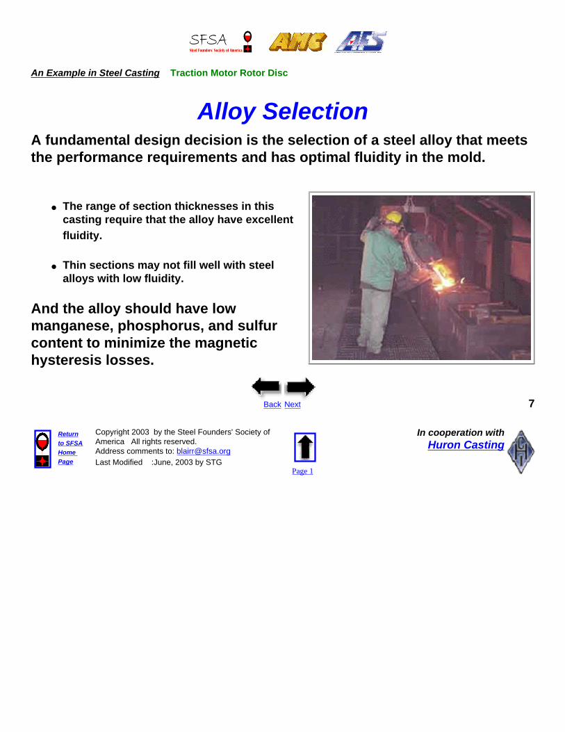
Alloy SelectionA fundamental design decision is the selection of a steel alloy that meets the performance requirements and has optimal fluidity in the mold.
● The range of section thicknesses in this casting require that the alloy have excellent fluidity.
● Thin sections may not fill well with steel alloys with low fluidity.
And the alloy should have low manganese, phosphorus, and sulfur content to minimize the magnetic hysteresis losses.
Back Next 7
Returnto SFSAHome Page
Copyright 2003 by the Steel Founders' Society of America All rights reserved. Address comments to: [email protected] Modified :June, 2003 by STG
Page 1
In cooperation withHuron Casting
An Example in Steel Casting Traction Motor Rotor Disc
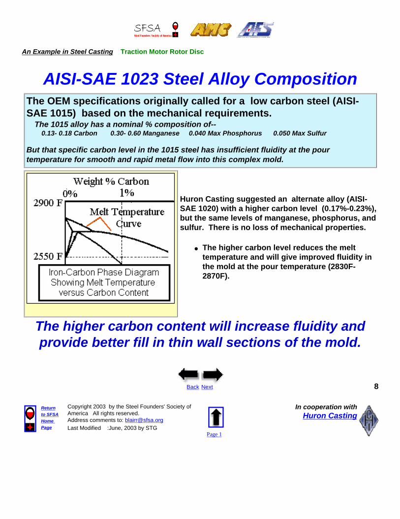
AISI-SAE 1023 Steel Alloy CompositionThe OEM specifications originally called for a low carbon steel (AISI-SAE 1015) based on the mechanical requirements. The 1015 alloy has a nominal % composition of-- 0.13- 0.18 Carbon 0.30- 0.60 Manganese 0.040 Max Phosphorus 0.050 Max Sulfur
But that specific carbon level in the 1015 steel has insufficient fluidity at the pour temperature for smooth and rapid metal flow into this complex mold.
Huron Casting suggested an alternate alloy (AISI-SAE 1020) with a higher carbon level (0.17%-0.23%), but the same levels of manganese, phosphorus, and sulfur. There is no loss of mechanical properties.
● The higher carbon level reduces the melt temperature and will give improved fluidity in the mold at the pour temperature (2830F-2870F).
The higher carbon content will increase fluidity and provide better fill in thin wall sections of the mold.
Back Next 8
Returnto SFSAHome Page
Copyright 2003 by the Steel Founders' Society of America All rights reserved. Address comments to: [email protected] Modified :June, 2003 by STG
Page 1
In cooperation withHuron Casting

An Example in Steel Casting Traction Motor Rotor Disc
The Molding MethodsThis casting could be produced by two types of molding methods.
GREEN SAND MOLDMoist, clay-bonded sand is tightly packed around a wood or metal pattern in mold boxes. The pattern halves are removed, and the mold is assembled with or without cores.
SHELL MOLDResin-coated sand is applied to heated metal patterns forming shell-like mold halves. The shell halves are bonded together with or without cores.
Back Next 9
Returnto SFSAHome Page
Copyright 2003 by the Steel Founders' Society of America All rights reserved. Address comments to: [email protected] Modified :June, 2003 by STG
Page 1
In cooperation withHuron Casting
An Example in Steel Casting Traction Motor Rotor Disc
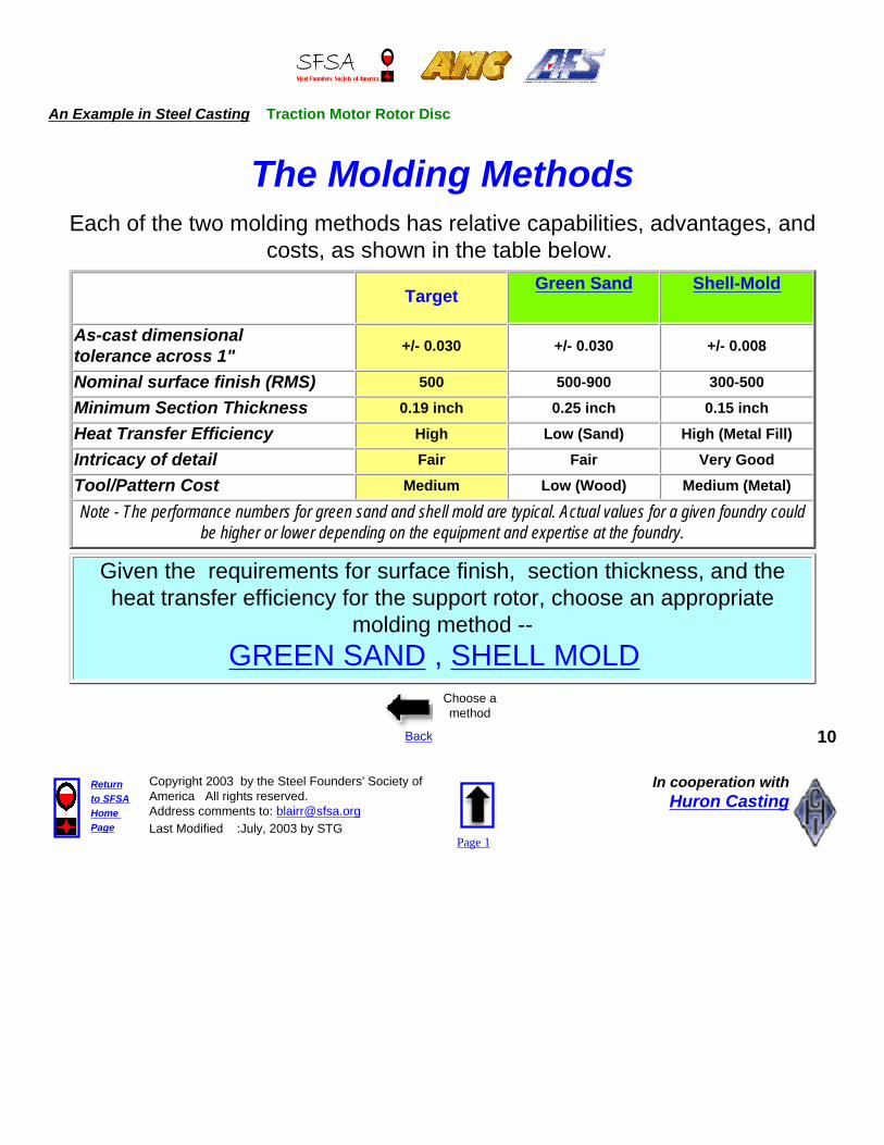
The Molding MethodsEach of the two molding methods has relative capabilities, advantages, and
costs, as shown in the table below.
TargetGreen Sand Shell-Mold
As-cast dimensional tolerance across 1" +/- 0.030 +/- 0.030 +/- 0.008
Nominal surface finish (RMS) 500 500-900 300-500Minimum Section Thickness 0.19 inch 0.25 inch 0.15 inchHeat Transfer Efficiency High Low (Sand) High (Metal Fill)Intricacy of detail Fair Fair Very GoodTool/Pattern Cost Medium Low (Wood) Medium (Metal)
Note - The performance numbers for green sand and shell mold are typical. Actual values for a given foundry could be higher or lower depending on the equipment and expertise at the foundry.
Given the requirements for surface finish, section thickness, and the heat transfer efficiency for the support rotor, choose an appropriate
molding method -- GREEN SAND , SHELL MOLD
Back
Choose a method
10
Returnto SFSAHome Page
Copyright 2003 by the Steel Founders' Society of America All rights reserved. Address comments to: [email protected] Modified :July, 2003 by STG
Page 1
In cooperation withHuron Casting

An Example in Steel Casting Traction Motor Rotor Disc
Green Sand Molding
Green Sand Molding
● Green sand molding can meet the baseline requirements for the rotor for as-cast tolerance, surface finish, detail level, and tool cost.
● But the green sand molding does not meet the requirement for minimum wall-thickness or heat-transfer efficiency.
Green sand molding is not the best choiceGo back and select another process.
Back 11
Returnto SFSAHome Page
Copyright 2003 by the Steel Founders' Society of America All rights reserved. Address comments to: [email protected] Modified :June, 2003 by STG
Page 1
In cooperation withHuron Casting

An Example in Steel Casting Traction Motor Rotor Disc
Shell Molding
Shell Molding
● Shell molding meets all the functional requirements for the rotor -- as-cast tolerance, surface finish, and level of detail.
● From a casting perspective, the shell mold offers a thin-wall capability and a heat transfer efficiency that cannot be achieved with green sand.
❍ The sand shell is set in a bed of metal shot which gives improved heat transfer during solidification.
● The higher cost of the metal tool for the shell mold is acceptable, given the production run and the production benefits.
Shell molding is the best choice.Go to the Next Design Issue!
Back Next 12
Returnto SFSAHome Page
Copyright 2003 by the Steel Founders' Society of America All rights reserved. Address comments to: [email protected] Modified :June, 2003 by STG
Page 1
In cooperation withHuron Casting
An Example in Steel Casting Traction Motor Rotor Disc
Component Orientation in the MoldIn mold design for castings, the orientation of the part in the mold is an important factor in producing a sound casting.
● Casting defects (porosity, inclusions), when they occur, tend to rise and segregate in the cope or upper section of gravity castings.
● Defects should also be minimized in any machined sections or surfaces.
Machined surfaces and critical features should be designed so that are molded in the drag or the lower section of the casting.
Back Next 13
Returnto SFSAHome Page
Copyright 2003 by the Steel Founders' Society of America All rights reserved. Address comments to: [email protected] Modified :June, 2003 by STG
Page 1
In cooperation withHuron Casting

An Example in Steel Casting Traction Motor Rotor Disc
Rotor Orientation in the Mold
The thin wall ribs next to the hub and the ribs on the base of the rotor are critical features which carry significant load and must be flaw free for strength and machinability.
● The rotor is oriented in the horizontal plane so that the parting line/plane is perpendicular to the rotor center line
The casting design engineer has two options for orienting the rotor in the mold --
● Option A - The rotor is oriented with the ribs in the lower section of the mold.
● Option B - The rotor is oriented with the ribs in the upper section of the mold.
Option A - Ribs Down
Option B - Ribs Up
Choose a preferred orientation -- Option A or B
Back
Select an Option 14
Returnto SFSAHome Page
Copyright 2003 by the Steel Founders' Society of America All rights reserved. Address comments to: [email protected] Modified :June, 2003 by STG
Page 1
In cooperation withHuron Casting

An Example in Steel Casting Traction Motor Rotor Disc
Option A - Ribs Down
Ribs Down
In Option A the thin wall ribs and the base ribs are oriented down in the bottom (drag section) of the mold.
● If inclusions or porosity form, they will segregate in the top of the casting in the center hub, where they will have minimum effect on mechanical properties.
The rotor ribs will be free of defects with this orientation.
The "ribs down" is the better orientation in the mold.Go to the next design topic
Back Next 15
Returnto SFSAHome Page
Copyright 2003 by the Steel Founders' Society of America All rights reserved. Address comments to: [email protected] Modified :June, 2003 by STG
Page 1
In cooperation withHuron Casting

An Example in Steel Casting Traction Motor Rotor Disc
Option B - Ribs Up
Ribs Up
In Option B the thin wall ribs and the base ribs are oriented up in the top (cope section) of the mold.
● If inclusions or porosity form, they will segregate in the ribs of the casting where they will act as structural flaws in the stressed ribs and cause problems in finish machining.
The ribs and machined surfaces will be at risk with this orientation.
The "ribs up" orientation is not the best approach.Go back and choose another orientation.
Back 16
Returnto SFSAHome Page
Copyright 2003 by the Steel Founders' Society of America All rights reserved. Address comments to: [email protected] Modified :June, 2003 by STG
Page 1
In cooperation withHuron Casting

An Example in Steel Casting Traction Motor Rotor Disc
Gating System DesignThe gating system (downsprues, runners, and gates) serves as the flow path for molten metal into the mold cavity. Proper design of the gating
system is critical to provide for uniform, controlled metal flow
Non-uniform, long path, and/or slow metal flow may produce unfilled sections or solidification shrinkage in the casting.
Too many gates and runners will also require additional molten metal and decrease the casting yield (metal in casting versus total metal poured)
Back Next 17
Returnto SFSAHome Page
Copyright 2003 by the Steel Founders' Society of America All rights reserved. Address comments to: [email protected] Modified :June, 2003 by STG
Page 1
In cooperation withHuron Casting

An Example in Steel Casting Traction Motor Rotor Disc
Gating System for the RotorThe thin wall ribs between the hub and the rim in the rotor must be filled rapidly and completely.
Two gating approaches were considered for effective metal flow into the ribs
● Approach A -- Four gates on the outside rim of the casting
● Approach B -- Two gates into the center hub of the casting.
Choose the Approach (A or B)
which will be more effective in filling the center ribs.
Approach A- Four Gates on the Rim
Approach B - Two Gates on the Hub
Back
Choose an approach 18
Returnto SFSAHome Page
Copyright 2003 by the Steel Founders' Society of America All rights reserved. Address comments to: [email protected] Modified :June, 2003 by STG
Page 1
In cooperation withHuron Casting
An Example in Steel Casting Traction Motor Rotor Disc
Approach A -- Four Gates on the Rim
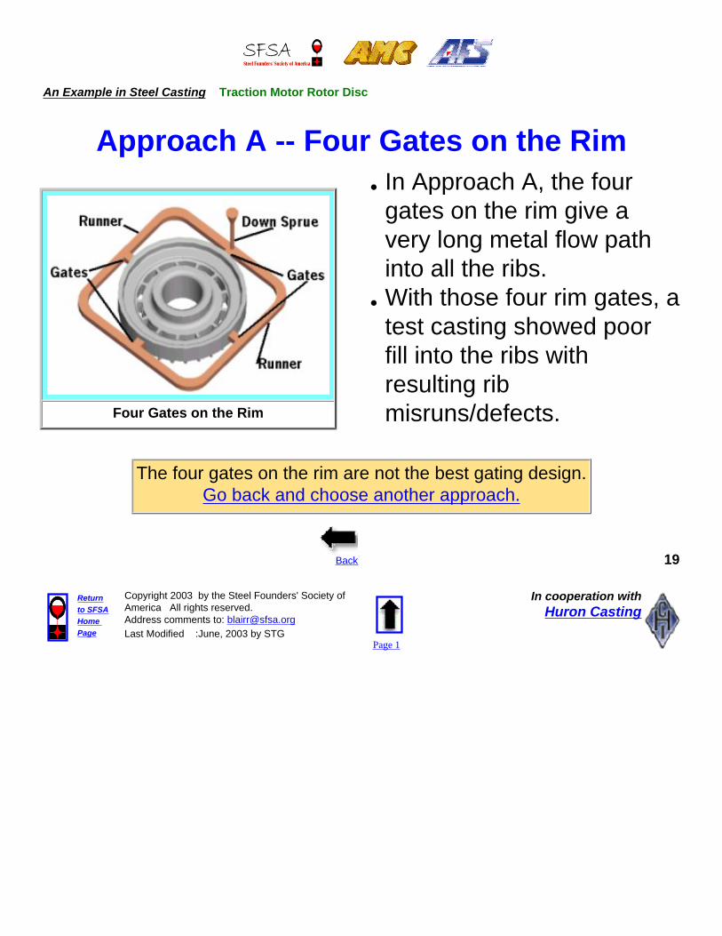
Four Gates on the Rim
● In Approach A, the four gates on the rim give a very long metal flow path into all the ribs.
● With those four rim gates, a test casting showed poor fill into the ribs with resulting rib misruns/defects.
The four gates on the rim are not the best gating design.Go back and choose another approach.
Back 19
Returnto SFSAHome Page
Copyright 2003 by the Steel Founders' Society of America All rights reserved. Address comments to: [email protected] Modified :June, 2003 by STG
Page 1
In cooperation withHuron Casting

An Example in Steel Casting Traction Motor Rotor Disc
Approach B --Two Gates on the Hub
Two Gates on the Center Hub
● In Approach B, the two gates on the center hub give fast, direct metal flow path into all the ribs.
● With the gates on the center hub, a test casting showed excellent metal fill into all the ribs.
The two gates into the center hub are the best gating design. Go on to the next design issue.
Back Next 20
Returnto SFSAHome Page
Copyright 2003 by the Steel Founders' Society of America All rights reserved. Address comments to: [email protected] Modified :June, 2003 by STG
Page 1
In cooperation withHuron Casting

An Example in Steel Casting Traction Motor Rotor Disc
Exothermic Sleeves on the RisersThe rotor rim has significant thermal mass and will solidify slowly. To
prevent shrinkage porosity in the rim, there must be a continuous source of molten metal feed into the rim during solidification.
● The perimeter risers feed molten metal into the rim. The smaller risers would normally solidify more quickly than the rim, which would shut off metal feed into the rim before it is fully solidified.
● To overcome this problem and to provide constant molten metal to the rim, the risers are surrounded with a 1/2" thick exothermic sleeve.
❍ The exothermic sleeves are cylinders comprised of a resin- bonded mixture of sand, aluminum, and an oxidizer. Heat is generated by the oxidation of the aluminum in a thermite-type reaction.
● The sleeve is a source of heat for the riser and keeps the riser molten and feeding metal into the rim, as the rim solidifies.
Four Risers on the Rim with Exothermic Sleeves
Back Next 21
Returnto SFSAHome Page
Copyright 2003 by the Steel Founders' Society of America All rights reserved. Address comments to: [email protected] Modified :June, 2003 by STG
Page 1
In cooperation withHuron Casting

An Example in Steel Casting Traction Motor Rotor Disc
Final Design of the Shell Mold Casting
Cope Half Shell Mold Drag Half Shell Mold
● The photos above show the two halves of the shell mold, prior to assembly.
● The 1/2" thick shells are formed from resin-impregnated sand directly on the iron tools and then heat treated to set their form.
● The two shells are then joined together to form the mold cavity and placed in the mold flask.
● The flask is filled with metal shot which supports the mold and acts as a thermal sink during metal solidification.
Back Next 22
Returnto SFSAHome Page
Copyright 2003 by the Steel Founders' Society of America All rights reserved. Address comments to: [email protected] Modified :June, 2003 by STG
Page 1
In cooperation withHuron Casting

An Example in Steel Casting Traction Motor Rotor Disc
Finishing and Machining
After solidification is complete, the rotor casting is -
● Removed from the flask and cleaned of sand in the shake-out process
● Surface cleaned by shot blasting ● Torch cut to remove the rigging ● Finish trimmed by grinding● Heat-treated at 1650F to normalize the
microstructure● Shot blasted to remove the heat-treatment scale
Rotor As-Cast
Rotor Machined
The shaft is then friction welded to the rotor and the assembly is machined on the critical surfaces
● The outer diameter and back face of the rim● The inner diameter bore in the hub● The two faces of the hub.
Back Next 23
Returnto SFSAHome Page
Copyright 2003 by the Steel Founders' Society of America All rights reserved. Address comments to: [email protected] Modified :June, 2003 by STG
Page 1
In cooperation withHuron Casting

An Example in Steel Casting Traction Motor Rotor Disc
Quality AssuranceThe rotor is inspected for quality, dimensions, and finish.
● Out of the mold, the casting is inspected visually for surface finish and for misruns in the ribs and surface holes and shrinkage in the hub and on the rim. As-cast dimensions are measured for tolerance.
● After heat-treatment, the rotor is inspected for hardness on the hub.
● After machining, the critical surfaces are measured for dimensions and surface finish.
Portable Hardness Tester
Back Next 24
Returnto SFSAHome Page
Copyright 2003 by the Steel Founders' Society of America All rights reserved. Address comments to: [email protected] Modified :June, 2003 by STG
Page 1
In cooperation withHuron Casting
An Example in Steel Casting Traction Motor Rotor Disc
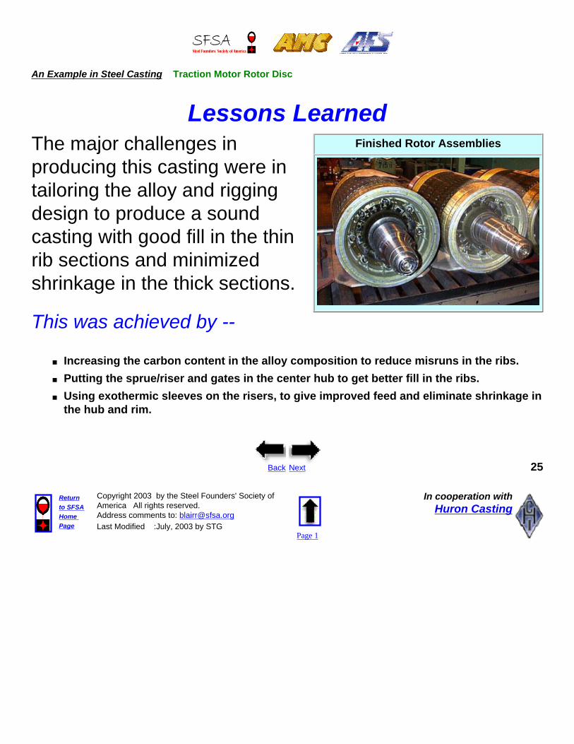
Lessons LearnedThe major challenges in producing this casting were in tailoring the alloy and rigging design to produce a sound casting with good fill in the thin rib sections and minimized shrinkage in the thick sections.
This was achieved by --
Finished Rotor Assemblies
■ Increasing the carbon content in the alloy composition to reduce misruns in the ribs.■ Putting the sprue/riser and gates in the center hub to get better fill in the ribs. ■ Using exothermic sleeves on the risers, to give improved feed and eliminate shrinkage in
the hub and rim.
Back Next 25
Returnto SFSAHome Page
Copyright 2003 by the Steel Founders' Society of America All rights reserved. Address comments to: [email protected] Modified :July, 2003 by STG
Page 1
In cooperation withHuron Casting

An Example in Steel Casting Traction Motor Rotor Disc
Summary
Steel Rotor Disc in Locomotive Traction Motor
● Alloy tailoring and effective design of the gates and risers insured the consistent production of a sound steel casting for this critical part in the traction motor of a diesel locomotive.
For further information on precision casting of steel alloys, contact --Terry Waitt at Huron Castings, Phone-- E-mail -- [email protected],
Web Site = http://www.huroncasting.com
Acknowledgment -- The metalcasting design studies are a joint effort of the
Steel Founders' Society of America and the American Foundry Society.Project funding was provided by the American Metalcasting Consortium Project, which
is sponsored by the Defense Logistics Agency, Attn: DLSC-T, Ft. Belvoir, VA, 22060-6221
Back 26
Returnto SFSAHome Page
Copyright 2003 by the Steel Founders' Society of America All rights reserved. Address comments to: [email protected] Modified :July, 2003 by STG
Page 1
In cooperation withHuron Casting