
A Design Methodology for Stealthy Parametric Trojans · PDF fileA Design Methodology for...
23
A Design Methodology for Stealthy Parametric Trojans and Its Application to Bug Attacks Samaneh Ghandali 1 , Georg T. Becker 2 , Daniel Holcomb 1 , and Christof Paar 1,2 1 University of Massachusetts Amherst, USA 2 Horst G¨ortz Institut for IT-Security, Ruhr-Universit¨ at Bochum, Germany [email protected], [email protected], [email protected], [email protected] Abstract. Over the last decade, hardware Trojans have gained increas- ing attention in academia, industry and by government agencies. In order to design reliable countermeasures, it is crucial to understand how hardware Trojans can be built in practice. This is an area that has re- ceived relatively scant treatment in the literature. In this contribution, we examine how particularly stealthy Trojans can be introduced to a given target circuit. The Trojans are triggered by violating the delays of very rare combinational logic paths. These are parametric Trojans, i.e., they do not require any additional logic and are purely based on subtle manipulations on the sub-transistor level to modify the parameters of the transistors. The Trojan insertion is based on a two-phase approach. In the first phase, a SAT-based algorithm identifies rarely sensitized paths in a combinational circuit. In the second phase, a genetic algorithm smartly distributes delays for each gate to minimize the number of faults caused by random vectors. As a case study, we apply our method to a 32-bit multiplier circuit resulting in a stealthy Trojan multiplier. This Trojan multiplier only computes faulty outputs if specific combinations of input pairs are applied to the circuit. The multiplier can be used to realize bug attacks, introduced by Biham et al. In addition to the bug attacks proposed previously, we extend this concept for the specific fault model of the path delay Trojan multiplier and show how it can be used to attack ECDH key agreement protocols. Our method is a general approach to path delay faults. It is a versatile tool for designing stealthy Trojans for a given circuit and is not restricted to multipliers and the bug attack. 1 Introduction Hardware Trojans have gained increasing attention in academia, industry and government agencies over the last ten years or so. There is a large body of research concerned with various methods for detecting Trojans, cf., e.g., [14]. On the other hand, there is scant treatment in literature about how to design Trojans. Nevertheless, Trojan detection and design are closely related: in order to design effective detection mechanisms and countermeasures, we need an understanding of how Hardware Trojans can be built. This holds in particular with respect to
Transcript of A Design Methodology for Stealthy Parametric Trojans · PDF fileA Design Methodology for...

A Design Methodology for Stealthy ParametricTrojans and Its Application to Bug Attacks
Samaneh Ghandali1, Georg T. Becker2, Daniel Holcomb1, and Christof Paar1,2
1University of Massachusetts Amherst, USA2Horst Gortz Institut for IT-Security, Ruhr-Universitat Bochum, Germany
[email protected], [email protected], [email protected],[email protected]
Abstract. Over the last decade, hardware Trojans have gained increas-ing attention in academia, industry and by government agencies. Inorder to design reliable countermeasures, it is crucial to understand howhardware Trojans can be built in practice. This is an area that has re-ceived relatively scant treatment in the literature. In this contribution,we examine how particularly stealthy Trojans can be introduced to agiven target circuit. The Trojans are triggered by violating the delays ofvery rare combinational logic paths. These are parametric Trojans, i.e.,they do not require any additional logic and are purely based on subtlemanipulations on the sub-transistor level to modify the parameters of thetransistors. The Trojan insertion is based on a two-phase approach. Inthe first phase, a SAT-based algorithm identifies rarely sensitized paths ina combinational circuit. In the second phase, a genetic algorithm smartlydistributes delays for each gate to minimize the number of faults causedby random vectors.As a case study, we apply our method to a 32-bit multiplier circuitresulting in a stealthy Trojan multiplier. This Trojan multiplier onlycomputes faulty outputs if specific combinations of input pairs are appliedto the circuit. The multiplier can be used to realize bug attacks, introducedby Biham et al. In addition to the bug attacks proposed previously, weextend this concept for the specific fault model of the path delay Trojanmultiplier and show how it can be used to attack ECDH key agreementprotocols.Our method is a general approach to path delay faults. It is a versatiletool for designing stealthy Trojans for a given circuit and is not restrictedto multipliers and the bug attack.
1 Introduction
Hardware Trojans have gained increasing attention in academia, industry andgovernment agencies over the last ten years or so. There is a large body ofresearch concerned with various methods for detecting Trojans, cf., e.g., [14]. Onthe other hand, there is scant treatment in literature about how to design Trojans.Nevertheless, Trojan detection and design are closely related: in order to designeffective detection mechanisms and countermeasures, we need an understandingof how Hardware Trojans can be built. This holds in particular with respect to
Trojans that are specifically designed to avoid detection. The situation is akin tothe interplay of cryptography and cryptanalysis.
There are several different ways that hardware Trojans can be inserted intoan IC [14]. The insertion scenarios that have drawn the most attention in thepast are hardware Trojans introduced during manufacturing by an untrustedsemiconductor foundry. One of the main motivations behind this is the fact thatthe vast majority of ICs world wide are fabricated abroad, and a foundry canpossibly be pressured by a government agency to maliciously manipulate thedesign. However, we note that a similar situation can exist in which the originalIC designer is pressured by her own government to manipulate all or some of theICs, e.g., those that are used in overseas products. Similarly, 3rd party IP coresare another possible insertion point.
The primary setting we consider is modification during manufacturing, butthe method also carries over to the other scenarios mentioned above. The Trojanwill be inserted by modifying a few gates at the sub-transistor level duringmanufacturing, so that their delay values increase. The goal is to select and chosethe delays such that only for extremely rare input combinations these delays addup to a path delay fault. There are many possible ways to increase the delaysin practice in stealthy ways. Since not a single transistor is removed or addedto the design and the changes to the individual gates are minor, the Trojanis very difficult to detect post-manufacturing using reverse-engineering, visualinspection, side-channel profiling or most other known detection methods. Dueto the extremely rare trigger conditions, it is also highly unlikely that the Trojanwill be detected during functional testing. Even full reverse-engineering of the ICwill not reveal the presence of the backdoor. Similarly, since the actual Trojanwill be inserted in the last step of the design flow, the Trojan will not be presentat higher abstraction levels such as the netlist. Accordingly, this type of Trojan isalso very interesting for the scenario of stealthy, government-mandated backdoors.The number of engineers that are aware of the Trojan would be reduced toa minimum since even the designers of the Trojan-infested IP core would notbe aware that such a backdoor has been inserted into the product. This canbe crucial to eliminate the risk of whistle blowers revealing the backdoor. Insummary, our method overcomes two major problems a Trojan designer faces,namely making the Trojan detection resistant and to provide a very rare triggercondition.
1.1 Related Work
The power of hardware Trojans was first demonstrated by King et al. in 2008by showing how a Hardware Trojan inserted into a CPU can enable virtuallyunlimited access to the CPU by an external attacker [15]. The Trojan presentedby King et al. was a Trojan inserted into the HDL code of the design. Similarly,Lin et al. presented a Hardware Trojan that stealthily leaks out the cryptographickey using a power side-channel [18]. This Hardware Trojan was also inserted atthe netlist or HDL level, similarly to the Hardware Trojans that were designedas part of a student Hardware Trojan challenge at ICCD 2011 [19]. How to buildstealthy Trojans at the layout-level was demonstrated in 2013 by Becker et al.
2

which showed how a Hardware Trojan can be inserted into a cryptographicallysecure PRNG or a side-channel resistant SBox only by manipulating the dopantpolarity of a few registers [4]. Another idea proposed in the literature is the ideaof building Hardware Trojans that are triggered by aging [23]. Such Trojans areinactive after manufacturing and only become active after the IC has been inoperation for a long time. Kumar et al. proposed a parametric Trojan [17] thattriggers probabilistically with a probability that increases under reduced supplyvoltage.
Compared to research concerned with the design of Hardware Trojans, con-siderably more results exist related to different Hardware Trojan detectionmechanisms and countermeasures. Most research focuses on detecting HardwareTrojans inserted during manufacturing. In many cases, a golden model is usedthat is supposed to be Trojan free to serve as a reference. One important questionis how to get to a Trojan-free golden model. One approach proposed is to usevisual reverse-engineering of a few chips to ensure that these chips were notmanipulated. For this the layout is compared to SEM images of the chip. In [3]methods of how to automatically do this are discussed. Please note that thatnot all Hardware Trojans are directly visibly in black-and-white SEM images.For example, to detect the dopant-level Hardware Trojans additional steps areneeded, e.g., the method presented by Sugawara et al. [24]. One motivation ofour work is that we might achieve an even higher degree of stealthiness by onlyslowing down transistors as opposed to completely changing transistors as hasbeen done in [4]. Such parametric changes can be done cleverly to make visualreverse-engineering very difficult as discussed in Section 3. Another approach toTrojan detection uses power profiles that are used to compare the chip-under-testwith previously recorded side-channel measurement of the golden chip. The mostpopular approach uses power side channels, first proposed by Agrawal et al. [2].The idea to build specific Trojan detection circuitry has also been proposed, e.g.,in [20]. However, these approaches usually suffer from the problem that a Trojancan also be inserted into such detection circuitry. Preventing Hardware Trojansinserted at the HDL level by third party IP cores has been discussed, e.g., in [13]and [26]. Efficient generation of test patterns for Hardware Trojans triggered bya rare input signals is the focus of work by Chakraborty et al. in [8] and Saha etal. in [21].
1.2 Our contribution
The main contributions of this paper can be summarized as follows:
– We introduce a new class of parametric hardware Trojans, the Path DelayTrojans. They posses the two desirable features that they are (i) very stealthyand thus difficult to detect with most standard methods and (ii) have veryrare trigger conditions.
– We present an automation flow for inserting the proposed style of Trojan.We propose an efficient, SAT solver-based path selection algorithm, whichidentifies suitably rare paths within a given target circuit. We also propose asecond algorithm, based on genetic algorithms, for distributing the necessary
3

delay along the rare path. The key requirement is to minimize the effect ofthe added delay on the remaining circuit.
– As a case study for the effectiveness of the proposed method, a Trojanmultiplier is designed. We were able to identify a rare path and performspecific delay modification in a 32-bit multiplier circuit model in such away that the faulty behavior only occurs for very few combinations of twoconsecutive input values. We note that the input space of the multiplieris (232)2 = 264 so that most random input values occur very rarely duringregular operation.
– We show how the Trojan multiplier can used for realizing the bug attack byBiham et al. [5, 6] and propose a related attack on the ECDH key agreementprotocol. We provide probabilities for this new bug attack variant. A precom-putation phase reduces the attack complexity and makes the attacks practicalfor real-world scenarios. We show that the attacker can engineer the failureprobability to the desired level by increasing the introduced propagationdelay of the Trojan.
2 Overview of the proposed method
This work implements Trojan functionality in a given target circuit by using pathdelay faults (PDF), without modification to logic circuit, to induce inaccurateresults for extremely rare inputs. Before describing the details of our method, wefirst define the notion of a viable delay-based Trojan in the unmodified HDL ofthe circuit as follows. A viable delay-based trojan must posses the following twoproperties.
Triggerability For secret inputs, which are known to the attacker, cause anerror with certainty or relatively high probability.
Stealthiness For randomly chosen inputs, cause an error with extremely lowprobability.
As shown in Fig. 1, our method of creating triggerable and stealthy delay-basedTrojans consists of two phases: path selection and delay distribution. We give anoverview of each phase here, and give detailed descriptions in Sec. 4.
Path Selection: The path selection phase finds a rarely sensitized path from theprimary inputs of a combinational circuit to the primary outputs. The algorithmchooses the path incrementally by adding gates to extend a subpath backwardtoward inputs and forward toward outputs. The selection of which gates to includeis guided by controllability and observability metrics so that the path will berarely sensitized. To ensure that the selected path can be triggered, a SAT-basedcheck is performed to ensure that the path remains sensitizable each time a gateis added. In addition to ensuring that the path is sensitizable, the SAT-basedcheck also provides the Trojan designer with a specific input combination thatwill sensitize the path. This input combination will later serve as the trigger forthe Trojan. Details of the path selection are given in Sec. 4.1.
Delay Distribution: After a rarely sensitized path is selected, the overall delayof the path must be increased so that a delay fault will occur when the path is
4

Fig. 1: Flowchart of the proposed method for creating a stealthy PDF (path delayfaults).
sensitized; this is required for the Trojan to be triggerable. However, any delayadded to gates on the selected path may also cause delay faults on intersectingpaths, which would cause more frequent errors and compromise stealthiness. Ourdelay distribution heuristic addresses this problem by smartly choosing delaysfor each gate to minimize the number of faults caused by random vectors. At thesame time, the approach ensures that the overall path delay is sufficient for thefault to occur when the trigger vectors are applied. Details of delay distributionare given in Sec. 4.2.
3 Delay Insertion
Delay faults occur when the total propagation delay along a sensitized circuitpath exceeds the clock period. Our algorithm causes delay faults by increasingthe delay of gates on a chosen path. While the approach is compatible with anymechanism for controlling gate delays, in this section we provide background onpractical methods that a Trojan designer might use to implement slow gates. Instatic CMOS logic, a path delay fault is not triggered by a single input vector,but instead is triggered by a sequence of two input vectors applied on consecutivecycles. The physical reason for delay being caused by a pair of inputs is that delaydepends on the charging or discharging of capacitances, and the initial statesof these capacitances in the second vector are determined as final states fromthe first vector. Assuming the capacitances need to be charged or dischargedalong a path, as is the case in delay faults, the delay of each gate depends onhow quickly it can charge or discharge some amount of capacitance on its outputnode, and diminishing the ability of a gate to do so will slow it down. There areseveral stealthy ways of changing a circuit to make gates slower. As an example,we list three methods below. We note that circuit designers typically face theopposite and considerably more difficult task, namely making gates fast. Theever-shrinking feature size of modern ICs is amenable to our goal of slowing gatesdown through minuscule alterations.
Decrease Width A gate library typically includes several drive strengths foreach gate type, corresponding to different transistor widths. A narrow tran-
5
sistor is slower to charge a load capacitance because transistor current islinear in channel width. A straightforward way to increase delay is to replacea gate with a weaker variant of the same gate, or to create a custom cellvariant with an extremely narrow channel. A limitation to using a downsizedgate is that an attacker who delayers the chip could potentially observe thesizing optically, depending on how much the geometry has been altered.
Raise Threshold A second way of increasing gate delay is to increase thresholdvoltages of selected transistors through doping or body biasing. Dual-Vtdesign is common in ICs and allows transistors to be designated as high orlow threshold devices; low threshold devices are fast and used where delay iscritical, and high threshold devices are slow and used elsewhere to reducestatic power. Typically no more than two threshold levels are used on a singlechip because creating multiple thresholds through doping requires additionalprocess steps, but in principle an arbitrary number of thresholds can becreated. Body biasing, changing the body-source voltage of MOSFETs, isanother way to change threshold and delay [16]; specifically, a reverse bodybias (i.e., body terminal at lower voltage than source) raises threshold voltageand slows down a device. Regardless whether the mechanism is doping orbody biasing, a raised threshold voltage will cause transistors to turn on laterwhen an input switches, and to conduct less current when turned on, so theoutput capacitance connected to the transistor will be charged or dischargedmore slowly. Both, changing to dopant concentrations and body biasing, aredifficult to detect, even with invasive methods.
Increase Gate Length Delay of chosen gates can be increased by gate lengthbiasing. Lengthening the gate of transistor causes a reduction in current, andtherefore increases delay [11]. Again, the likelihood of detection depends onthe degree of the alteration.
WL
n+ n+p IN
VINVOUT
(a) Annotated NMOS transistor
0
1
0ps 50ps 100ps
Volt
age
Curr
ent
Time
VinVout
iN
(b) Switching Event
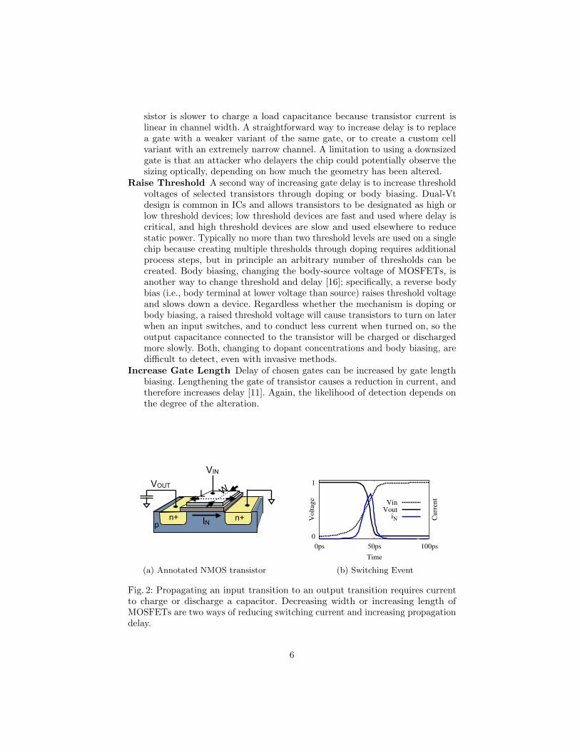
Fig. 2: Propagating an input transition to an output transition requires currentto charge or discharge a capacitor. Decreasing width or increasing length ofMOSFETs are two ways of reducing switching current and increasing propagationdelay.
6

We note that the methods sketched above (and other slow-down alterations)can be combined such that each manipulation is relatively minor and, thus, moredifficult to detect.
4 Finding a Trojan Path
Fundamentally, the challenge in designing and validating triggerable and stealthydelay-based Trojans is that timing and logical sensitization cannot be decoupled.Regardless of the type of path sensitization considered, the probability of causingan error is not a well-defined concept until after delays are assigned. Therefore,when designing a candidate Trojan, path selection and delay assignment mustboth be considered. We will use a heuristic for this which combines logical pathselection and delay distribution along a chosen path.
4.1 Phase I: Rare Path Selection
In this phase we try to select a path among huge number of paths existing in thenetlist of a multiplier circuit, in such a way that random inputs will very rarelysensitize the path. The rareness is a first step towards ensuring stealthiness ofthe Trojan.
Controllability and Observability: Before giving our algorithm, we intro-duce several preliminaries. First, we note that every node in the circuit has acontrollability metric and an observability metric associated with the 0 valueand the 1 value. Controllability and observability are common metrics used intesting. Controllability of a 0 or 1 value on a circuit node is an estimate of theprobability that a random input vector would induce that value on that node.Observability of a 0 or 1 value on a node is an estimate of the probability withwhich that value would propagate to some output signal when a random vectoris applied. For rareness, we seek a path that includes low controllability nodesand low observability nodes, as this would indicate that the values on the pathrarely occur randomly, and when they do occur they are usually masked fromreaching the outputs. We estimate controllability using random simulation, andobservability using random fault injection [12].
Timing Graph: The propagation delays of logic paths in combinational VLSIcircuits are typically represented using weighted DAGs called timing graphs.Each node in a circuit will have two nodes in the timing graph, representingrising and falling transitions on the node; we use the terms transition and nodeinterchangeably when discussing timing graphs. A directed edge between twonodes exists if the transition at the tail of the edge can logically propagate tothe one at the head. The edges that exist in the timing graph therefore dependon the logic function of each gate in the circuit (see Fig. 3).
For example, an AND gate with inputs A and B, and output X, will havean edge from A ↑ to X ↑, from A ↓ to X ↓, from B ↑ to X ↑, and from B ↓ to
7

Fig. 3: Circuit and corresponding timing graph.
X ↓, but will not have an edge from A ↑ to X ↓ because a rising transition on anAND gate input cannot induce a falling output. In timing analysis, e.g. STA, theedge weights of a timing graph represent propagation delay, but for our purposeof path selection, the delays are ignored and we utilize only the connectivity ofthe timing graph.
Selecting a Path Through Timing Graph: Our path selection techniqueseeks to find a path π through the timing graph of the circuit that is rarelysensitized. Note that the delays are not considered in this phase of the work.Path π is initialized to contain a single hard to sensitize transition somewhere inthe middle of the circuit. More formally, the starting point for the path searchis a rising or falling transition on a single node such that the product of its 0and 1 controllability values is the lowest among all nodes in the circuit. Thisinitial single-node path π is then extended incrementally backward until reachingthe primary inputs (PIs), and extended incrementally forward until reaching theprimary outputs (POs). The backward propagation is given in Alg. 1, and theforward propagation is given in Alg. 2.
First we explain the backward propagation heuristic in Alg. 1. Starting fromthe first transition (i.e. the tail) on the current path π, we repeatedly try to extendthe path back toward the PIs by prepending one new transition to the path.To select such a transition, the algorithm creates a list of candidate transitionsthat can be be prepended to the path. In the timing graph, these candidatesare predecessor nodes to the current tail of π. The list of candidate nodes isthen sorted according to diffj, the difficulty of creating the necessary conditionsto justify the transition. See Tab. 3 in the appendix for the formula used tocompute diffj for each transition on each gate type. Note that our difficultymetric is weighted to always prefer robust sensitization first, and only resort tonon-robust sensitization when there are no robustly sensitizable nodes in the listof candidates. Whenever a node is prepended to π to create a candidate path π′
(line 5) the sensitizability of π′ is checked by calling check-sensitizability function.In this function SAT-based techniques [9] are used to check sensitizability of apath and to find a vector pair that justifies and propagates a transition alongthe path (line 6). If the SAT solver returns SAT, then path π′ is known to be asubpath of a sensitizable path from PIs to POs. Because the candidates are visitedin order of preference, there is no need to check other candidates after finding a
8

first candidate that produces a sensitizable path. At this point, the algorithmupdates π to be π′ and the algorithm exits the for loop having extended the pathby one node. If this newly added tail node is not a PI, then the algorithm willagain try to extend it backwards.
Algorithm 1: Extend path backward to PIs while trying to maximizedifficulty of justification while ensuring that path will remain sensitizable.
Require: A sensitizable subpath π in timing graph of circuit.Ensure: A longer sensitizable subpath π in timing graph that starts at a PI1: while tail(π) /∈ PIs do2: candidates← (∀n|n ∈ pred(tail(π))) {transitions that can be prepended to π}3: candidates.order(diffj) {Order candidates by difficulty of justification}4: for n′ ∈ candidates do5: π′ ← (n′, π) {Create a candidate path by prepending current path}6: if check-sensitizability(π′) = SAT then7: π ← π′ {candidate accepted, update path π with new tail}8: Exit for loop9: end if
10: end for11: end while
The forward propagation algorithm (Alg. 2) is similar to the aforementionedbackward propagation algorithm, except that it adds nodes to the head of thepath until reaching POs. At each step of the algorithm, a list of candidates isagain formed. In this case, the candidates are successors of the head of the path(line 2) instead of predecessors of the tail, and they are ordered according todifficulty of propagation (line 3) instead of difficulty of justification. Each time anew candidate path is created by adding a candidate node to the existing path,a sat check is again performed to ensure that the nodes are only added to π if itremains sensitizable (line 6).
4.2 Phase II: Delay Distribution
Once a path is selected, we must increase the delay of the path so that the totalpath delay will exceed the clock period and an error will occur when the path issensitized. Yet, we must be careful in choosing where to add delay on the path,because the gates along the chosen path are also part of many other intersectingor overlapping paths. Any delay added to the chosen path therefore may causeerrors even when the chosen path is not sensitized. To ensure stealthiness, wemust minimize the probability of this by smartly deciding where to add delaysalong the path.
We use a genetic algorithm to decide the delay of each gate that will causethe Trojan to be stealthy. Genetic algorithm is an optimization technique thattries to minimize a cost function by creating a population of random solutions,and repeatedly selecting the best solutions in the population and combining and
9

Algorithm 2: Extend path forward to POs while trying to maximizedifficulty of propagation while ensuring that path will remain sensitizable.
Require: A sensitizable subpath π in timing graph of circuit.Ensure: A longer sensitizable subpath π in timing graph that ends at a PO1: while head(π) /∈ POs do2: candidates← (∀n|n ∈ succ(head(π))) {transitions that can be appended to π}3: candidates.order(diffp) {Order candidates by difficulty of propagation}4: for n′ ∈ candidates do5: π′ ← (π, n′) {Create a candidate path by appending to current path}6: if check-sensitizability(π′) = SAT then7: π ← π′ {candidate accepted, update path π with new head}8: Exit for loop9: end if
10: end for11: end while
mutating them to create new solutions; the quality of each solution is evaluatedaccording to a fitness function. We use the genetic algorithm function ga inMatlab [1], and do not utilize any special modifications to the genetic algorithmimplementation. Our interaction with the ga function is limited to providingconstraints that restrict the allowed solution space, and a fitness function forevaluating solutions. We describe these constraints and fitness function here.
Constraint on Total Path Delay Given a chosen path π comprising gates(p0, p1, . . . , pn) and assuming a target path delay of D, the genetic algorithmdecides the delay of each gate on the path. Our first constraint therefore specifiesthat the sum of assigned delays along the path is equal to the target path delay D.To cause an error, D must exceed the clock period, and we later show advantagesof using different values of D.
D =
n∑i=0
di (1)
Constraint on Delay of Each Gate Next we provide the genetic algorithmwith a hint that helps it to discover reasonable delays for each gate. In this step,we use d′i to represent the nominal delay of the ith gate on chosen path π, andsi to represent the a slack metric associated with the same gate. Each slackparameter si describes how much delay can be added to the corresponding gatewithout causing the path to exceed the clock period. Because the targeted pathdelay D does exceed the clock period, gate delays are allowed to exceed theircomputed slack. The slack for each gate is computed as a function of the nominaldelay of the gate, data dependency, and the clock period [25] [10]. The followingequation shows the constraint on delay of gate i, where c is a constant.
d′i + si − c ≤ di ≤ d′i + si + c (2)
10

Fitness Function Simply stated, the cost function that we want to minimizeis the probability of causing an error when random input vectors are appliedto the circuit. Because there is no simple closed-form expression for this, weuse random simulation to evaluate the cost of any delay assignment. When thegenetic algorithm in Matlab needs to evaluate the cost of a particular delayassignment, it does so by executing a timing simulator. The timing simulator, inour case ModelSim, applies random vectors to the circuit-under-evaluation anda golden copy of the circuit and compares the respective outputs to count thenumber of errors that occur. These errors are caused by the delay assignmentsin the circuit-under-evaluation. The cost that is returned from the simulatoris the percentage of inputs that caused an error for this delay assignment. Asthe genetic algorithm proceeds through more and more generations of solutions,the quality of the solutions improve. Matlab’s genetic algorithm implementationcomes with a stopping criterion, so we simply allow the algorithm to run untilcompletion.
5 Experimental Results
We now evaluate the effectiveness of our method of designing Trojans, using a32× 32 Wallace tree multiplier as a test case. The circuit has a nominal criticalpath of length 128, and the delay of this path is 2520 ps.
5.1 Evaluation of Phase I (Path Selection)
To evaluate the ability of our path selection algorithm (Sec. 4.1) to find a rarepath, we compare the stealthiness of the path selected by the algorithm againstthe stealthiness of 750 randomly chosen paths. For each of these paths, we seekto find how often an error would occur under random inputs if the path delay isincreased. We measure this by uniformly increasing the delay of each gate on thepath such that the total delay of the path is 5040 ps, which is twice the delay ofthe nominal critical path. After the delay modification, 10,000 random vectorsare applied and the number of error-causing vectors is counted. The histogramof Fig. 4 shows the result; the x-axis represents error rates, and the y-axis showshow many of the paths have each error rate. The result shows that a majorityof paths would cause frequent errors if their delay is increased, and these pathsare thus unsuitable for stealthy Trojans. The rare path (RP) selected by ouralgorithm caused an error for only 4 of 10,000 vectors. By comparison, the bestof the random paths caused an error in 174 of 10,000 vectors. In this experiment,the path chosen by the path selection algorithm is 43x less likely to cause an errorthan the best of 750 random paths. Note that this experiment is conservativein that the amount of additional delay added is very large, and the delay is notsmartly distributed along the path to minimize detection.
5.2 Evaluation of Phase II (Delay Distribution)
To evaluate the effectiveness of our delay distribution method, we apply theproposed method (Sec. 4.2) on 10 paths from the multiplier. These 10 paths
11

Fig. 4: Fault simulation of rare path and 750 random paths of 32× 32 Wallacetree multiplier.
Fig. 5: Error probability of circuit before and after optimizing delay assignmentof rare path and 9 other paths in a 32× 32 Wallace tree multiplier.
are the rare path chosen by the path selection algorithm, and 9 paths randomlyselected from the set of all paths that caused less than 10% error rates in Fig. 4.For each of these paths, we use the genetic algorithm to optimally allocate atotal delay of 3276 ps (i.e. 1.3 times of the delay of the nominal critical path)over the path, and then evaluate the error probability using random simulationwith 5,000,000 vectors. Fig. 5 shows the error probability of each path beforeand after applying our proposed delay distribution method. In each case, theoptimization step reduces the probability of causing an error by at least 3.5x.For the rare path (RP), just one error in 5,000,000 vectors is caused after delaydistribution. This result shows that, for a given total path delay, optimizing the
12

delay assignment along the path can reduce the probability of having an errorwhen random vectors are applied. It is important to note that this improvementin stealthiness comes from minimizing the side effects of the added delay, anddoes not impact triggerability when vectors are applied that actually sensitizethe entire chosen path.
5.3 Overall Evaluation
We evaluate our overall methodology comprising path selection and delay dis-tribution on the 32× 32 Wallace Tree multiplier circuit. Instead of assuming aparticular clock frequency, here we examine whether it is possible to add delay tothe chosen rare path such that the circuit will (1) exceed the nominal critical pathdelay of 2520 ps when the applied input sensitizes the rare path, and (2) alwayshave delay of less than 2520 ps otherwise. We first distribute delay uniformlyover the path, and then apply the same total delay to the path but distribute itusing the genetic algorithm (Sec. 4.2). The results are shown in Tab. 1. Despitesimulating 260 million random vectors, we are unable to randomly discover anyvectors in which the circuit delay exceeds 2520 ps. Yet, when applying a vectorpair produced by our SAT-based sensitization check, we observe that the chosenpath delay does exceed 2520 ps. As simulating 260 million vectors on a circuit thissize already used more than 240 hours of computation on an AMD Opteron(TM)Processor running at 2.3GHz with 8 cores and 64 GB RAM, it will becomequite expensive to check increasing numbers of vectors beyond 260 million. Thishighlights a significant challenge: given a space of 2128 possible vector pairs thatmight cause an error, it is very hard to estimate the probability of an error thatis sufficiently rare. If the probability of error is around or above roughly 2−26,then random simulation will suffice to find a few errors and estimate the errorprobability. If the probability of error is below roughly 2−98 it would be possibleto use SAT to exhaustively enumerate all 230 vectors that would cause an error.Unfortunately, for very interesting region of error probabilities between 2−26 and2−98 there is no clear solution for estimating the error probabilities.
When the amount of delay added to the rare path is increased, and theprobability of error grows above 2−26, the error probability can feasibly beestimated with random simulation. In this regime, we can evaluate the tradeoff ofdelay and trigger probability. For example, when the chosen path is given a totaldelay of 3150 ps allocated using genetic algorithm for delay distribution, andthe circuit is operated at a clock period of 2800 ps (as might be reasonable for anominal critical path of 2520 ps) an erroneous output occurs with probabilityof roughly 2−24 (once every 16 million multiplications) when random inputs areapplied. The overall tradeoff is shown in Fig. 6 for different clock periods. Onecan exploit this tradeoff to create a desired error probability by increasing ordecreasing the total amount of delay added to the chosen path.
6 Bug Attack On ECDH with a Trojan Multiplier
The main motivation of choosing a multiplier as our case study is the bug attackpaper by Biham et al. [5, 6]. They showed how several public key implementations
13
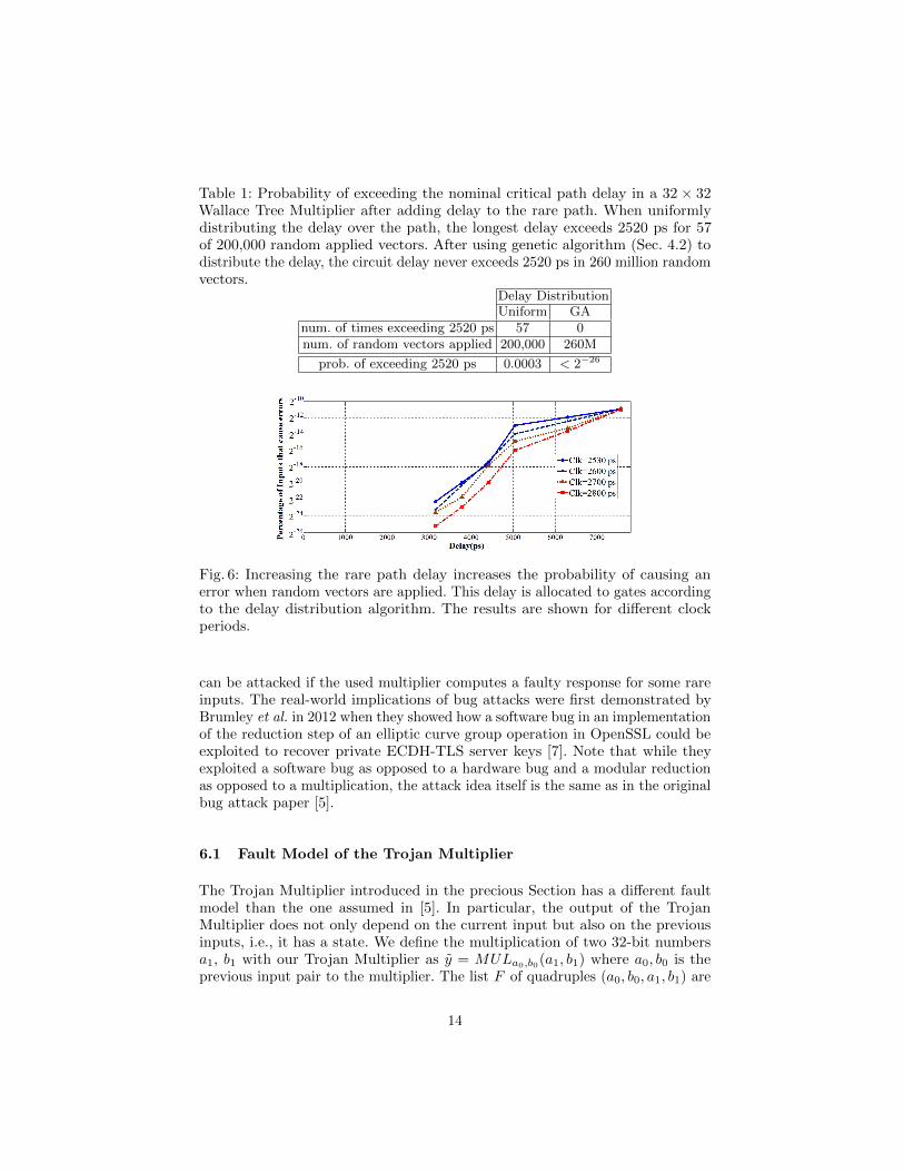
Table 1: Probability of exceeding the nominal critical path delay in a 32 × 32Wallace Tree Multiplier after adding delay to the rare path. When uniformlydistributing the delay over the path, the longest delay exceeds 2520 ps for 57of 200,000 random applied vectors. After using genetic algorithm (Sec. 4.2) todistribute the delay, the circuit delay never exceeds 2520 ps in 260 million randomvectors.
Delay DistributionUniform GA
num. of times exceeding 2520 ps 57 0num. of random vectors applied 200,000 260M
prob. of exceeding 2520 ps 0.0003 < 2−26
Fig. 6: Increasing the rare path delay increases the probability of causing anerror when random vectors are applied. This delay is allocated to gates accordingto the delay distribution algorithm. The results are shown for different clockperiods.
can be attacked if the used multiplier computes a faulty response for some rareinputs. The real-world implications of bug attacks were first demonstrated byBrumley et al. in 2012 when they showed how a software bug in an implementationof the reduction step of an elliptic curve group operation in OpenSSL could beexploited to recover private ECDH-TLS server keys [7]. Note that while theyexploited a software bug as opposed to a hardware bug and a modular reductionas opposed to a multiplication, the attack idea itself is the same as in the originalbug attack paper [5].
6.1 Fault Model of the Trojan Multiplier
The Trojan Multiplier introduced in the precious Section has a different faultmodel than the one assumed in [5]. In particular, the output of the TrojanMultiplier does not only depend on the current input but also on the previousinputs, i.e., it has a state. We define the multiplication of two 32-bit numbersa1, b1 with our Trojan Multiplier as y = MULa0,b0(a1, b1) where a0, b0 is theprevious input pair to the multiplier. The list F of quadruples (a0, b0, a1, b1) are
14

all input sequences for which the Trojan Multiplier computes a faulty response:
For all (a0, b0, a1, b1) ∈ F : y = MULa0,b0(a1, b1) 6= y = a1 · b1For all (a0, b0, a1, b1) /∈ F : y = MULa0,b0(a1, b1) = y = a1 · b1
(3)
Outputs computed with the Trojan Multiplier are always represented with a tilde.An ECC scalar multiplication of point Q ∈ E with an integer k is denoted asR = k ·Q. An elliptic curve scalar multiplication using the Trojan Multiplier isdenoted with an �, i.e., R = k �Q. In the following we assume that an attackerhas knowledge of the Trojan Multiplier or access to a chip with the TrojanMultiplier such that the attacker knows for which inputs R 6= R.
The attack complexity strongly depends on the probability that a multiplica-tion results in a faulty response. In order to be able to compute this probabilitywe make following definitions:
1. PM(a1,b1): Probability that for two random 32-bit integers a1, b1 there exitsat least one pair of 32-bit integers a0, b0 such that y = MULa0,b0(a1, b1)computes a faulty response
2. PM(a1): Probability that for a random 32-bit integers a1 there exits at least onetriplet of 32-bit integers a0, b0, b1 such that y = MULa0,b0(a1, b1) computesa faulty response. Probability PM(b1) is defined in the same fashion.
3. PM(a0,b0|a1,b1): Probability that for two random 32-bit integers a0, b0 andtwo given integers a1, b1 the multiplication y = MULa0,b0(a1, b1) computesa faulty response if there exists at least one other input pair a′0, b
′0 for which
y = MULa′0,b
′0(a1, b1) computes a faulty response
4. PM(a0|a1,b1=b0): Probability that for a random 32-bit integers a0, and twogiven integers a1, b1 the multiplication y = MULa0,b0(a1, b1) with b0 = b1computes a faulty response if there exists at least one other input pair a′0, b
′0
for which y = MULa′0,b
′0(a1, b1) computes a faulty response
Furthermore, we make following assumptions regarding these probabilities forthe Trojan Multiplier :
1. PM(a1) ≈ PM(b1) and PM(a1,b1) = PM(a1) · PM(b1)
2. PM(a0,b0|a1,b1) ≈ 0.093. PM(a0|a1,b1=b0) ≈ 0.18
Assumption (1) follows from the fact that both inputs have the same impacton the propagation path of the signal. Hence it is reasonable that both valuesare equally important to determine if a multiplication fails. Assumption (2) isbased on experimental results in which 892 out of 10,000 multiplication failedwhen a0 and b0 are changed randomly while keeping a1,b1 constant. Assumption(3) is based on a similar experiment in which 1813 out of 10,000 multiplicationfailed when a0 was changed randomly and b0 was fixed to b0 = b1 and a1 waskept constant as well.
6.2 Case Study: An ECDH implementation with MontgomeryLadder
For our case study we assume a 255-bit ECDH key agreement with a static publickey. Furthermore, we assume the implementation uses the Montgomery Ladder
15

scalar multiplication. The ECDH key agreement works as follows: Given are astandardized public curve E (e.g. Curve25519) and the point G ∈ E. The privatekey of the server is a 255 bit integer ks and the corresponding public key isQs = ks ·G. The key agreement is started by the client by choosing a random255-bit integer kc and computing Qc = kc ·G. The client sends Qc to the serverand computes the shared key R = ks ·Qs. The server computes the shared secretkey R using Qc and his secret key ks by computing R = kS · Qc. Usually, thekey agreement is followed by a handshake to ensure that both the client and theserver are now in possession of the same shared session key R.
The general idea of the bug attack is that the attacker makes a key guessof the first l bits of the secret key Ks. Then the attacker searches for a pointQ = m · G such that the scalar multiplication R = ks � Q results in a failureif, and only if, the most significant bits of ks are indeed the l bits the attackerguessed. The attacker then sends Q to the server and completes the ECDH keyexchange protocol by making a handshake with the shared key R = m ·Qs. If thishandshake fails, the expected multiplication error in the Trojan Multiplier hasoccurred and hence, the attacker knows that his key guess is correct. This waymore and more bits of the key are recovered consecutively. In the MontgomeryLadder scalar multiplication only one bit of the key is processed in each ladderstep and the attack works as follows:
1. Input: Elliptic curve E with point G ∈ E and public server key Qs ∈ E2. Initialization: Set k = 1(2)3. Repeat for key bit 2 to 255:
(a) Define k0 = k||0(2) [Append a zero to the key k](b) Define k1 = k||1(2) [Append a one to the key k](c) Repeatedly choose a value m and compute Q = m ·G until:
(Pi = ki �Q) 6= (Pi = ki ·Q) for i ∈ {0, 1}(Pj = kj �Q) = (Pj = kj ·Q) for j 6= i, j ∈ {0, 1}
(d) Send Q to the server and complete handshake with R = m ·Qs
(e) If handshake failed, set k = ki, else set k = kj
The attack described above is a straight forward adaption of the bug attackfrom [7]. However, in the Trojan multiplier scenario the attack can be improvedsignificantly by adding a precomputation step. The main idea is to not userandomly generated points Q in step 3.c) but to use points Q in which the x-coordinate Qx contains a b1 for which the Trojan Multiplier y = MULa0,b0(a1, b1)has a high chance to return a faulty response. That is, b1 is one of the inputsfor which the Trojan Multiplier fails. In each step of the Montgomery Ladderalgorithm the projective coordinate Z2 is computed with Z2 ← Z2 ·Qx
1 Hence,Qx, and therefore also b1, is used in every ladder step. Furthermore, the value Z2
is different depending on the currently processed key bit. Our improved attacktargets this 255-bit integer multiplication Z2 ·Qx to find a Q such that (Pi 6= Pi)
while (Pj 6= Pj) as needed in step 3.c) of the attack algorithm.Unfortunately, the attacker cannot freely choose Q since the attacker needs
to know m such that Q = m ·G to finish the handshake. Instead of computing
1 See Appendix B of the IACR ePrint version for the Montgomery Ladder algorithm.
16

suitable points for each attack, we propose to search for t suitable points Qduring a precomputation step as described below:
1. Input: Elliptic curve E with point G ∈ E2. Initialization: m = 1, Q = G3. Repeat t times:
(a) m = m+ 1, Q = Q+G(b) If Qx contains b1, store m and Q in list L
To compute the probability that the 255-bit integer multiplication Z2 ·Qx failsthe used multiplication algorithm is important. We assume that the schoolbookmultiplication is used. One 255-bit schoolbook multiplication consists of 64multiplications of which 8 have b1 as an operand. Since one of these multiplicationis a 31-bit multiplication and we assume that only 32-bit multiplications cantrigger the Trojan, 7 32-bit multiplications with b1 that can trigger the Trojanare performed in each ladder step. Furthermore, due to the FOR loops in theschoolbook multiplication, in 6 of these 7 multiplications b0 = b1, i.e., the secondoperand in the multiplication remains unchanged. Note that PM(a0|a1,b1=b0) ≈0.18 and hence this is actually not a problem but rather helpful. The averagenumber AQ of points Q that need to be tested until a failure occurs for key bit 1or 0 is therefore:
AQ =1
2· 1
PM(a1) · PM(a0|a1,b1=b0) · 6 + PM(a1) · PM(a0,b0|a1,b1) · 1
Let us assume that the attacker tries to find a point Q for key bit i. Since theattacker searches for a fault in the last Montgomery Ladder step, for every pointQ the attacker needs to compute i− 2 Montgomery Ladder steps (for the firstkey bit no step is needed) and then two Montgomery Ladder steps for key bit 1and 0 respectively to check if the multiplication fails. Hence, in total the attackerneeds an average of AM Montgomery Ladder steps to recover a 255 bit key:
AM =
255∑i=2
(i ·AQ) =2552 + 255
2·AQ ≈ 216 ·AQ
To compute t points Q during the precomputation such that b1 is in Qx theattacker needs in average
AP = t · 1
PM(b1)
point additions. We chose t = 16 ·AQ which results in a failure probability ofca. 3.3 · 10−8 which should be small enough for all reasonable attack scenarios.Table 2 summarizes the attack complexity for our improved bug attack withprecomputation for different parameters for the Trojan Multiplier. To put thesenumbers into perspective, the hardware implementation of curve25519 presentedin [22] can compute roughly 239.3 Montgomery Ladder steps per second on a XilinxZynq 7020 FPGA. Hence, especially for a failure probability of PM(a1,b1) = 2−48
the attack complexity of 239 Montgomery ladder steps (and 250 point additionsthat only need to be done once) is quite practical in a real-world scenario. On the
17

Table 2: Attack complexity of the proposed improved Bug Attack using theTrojan Multiplier assuming a 256 bit curve.
PM(a1,b1) 2−64 2−48 2−32
Precomputation complexity (point additions) 266.8 250.8 234.8
Storage Requirement 14 PB 55 TB 215 GB
Attack complexity (scalar multiplications) 230.8 222.8 214.8
Attack complexity (Montgomery Ladder Steps) 246.8 238.8 230.8
other hand, the probability that the Trojan is triggered unintentionally duringnormal operation is about 2−37 which is low enough to not cause problems (seeAppendix 19 for details).
7 Conclusion
This paper introduced a new type of parametric hardware Trojans based on rarely-sensitized path delay faults. While hardware Trojans using parametric changes(i.e. that only modify the performance/parameters of gates) have been proposedbefore, the previously proposed parametric hardware Trojans cannot be triggereddeterministically. They are instead either triggered after time by aging [23],triggered randomly under reduced voltage [17] or are always on and can leak keysusing a power side-channel [4]. In contrast, the proposed parametric hardwareTrojan in this paper can be triggered by applying specific input sequences tothe circuit. Hence, this paper introduces the first trigger-based hardware Trojanthat is realized solely by small and stealthy parametric changes. To achieve this,a SAT-based algorithm is presented which efficiently searches a combinationalcircuit for paths that are extremely rarely sensitized. A genetic algorithm is thenused to distribute delays over all the gates on the path so that a path delay faultoccurs when trigger inputs are applied, while for other inputs the timing criteriaare met. In this way, a faulty response is computed only for a very small subsetof input combinations.
To demonstrate the usefulness of the proposed technique, a 32-bit multiplieris modified so that, for some multiplications, faulty responses are computed.These faults can be so rare that they do not interfere with normal operationsbut can still be used by the Trojan designer for a bug attack against publickey algorithms. As a motivating example, we showed how this can be achievedfor ECDH implementations. Please note that while we used a multiplier asour case study, the general idea of path delay Trojans and the tool-flow andalgorithms presented in this paper are not restricted to multipliers. Hence, thiswork shows that by only making extremely stealthy parametric changes to adesign, a malicious factory could insert backdoors to leak out secret keys.
References
1. Genetic Algorithm. http://www.mathworks.com/discovery/genetic-algorithm.html, [Accessed: 2016-02-01]
2. Agrawal, D., Baktir, S., Karakoyunlu, D., Rohatgi, P., Sunar, B.: Trojan Detectionusing IC Fingerprinting. In: IEEE Symposium on Security and Privacy (SP 2007).pp. 296–310 (2007)
3. Bao, C., Forte, D., Srivastava, A.: On reverse engineering-based hardware trojandetection. Computer-Aided Design of Integrated Circuits and Systems, IEEETransactions on 35(1), 49–57 (Jan 2016)
4. Becker, G.T., Regazzoni, F., Paar, C., Burleson, W.P.: Stealthy dopant-level hard-ware trojans. In: Cryptographic Hardware and Embedded Systems-CHES 2013, pp.197–214. Springer (2013)
5. Biham, E., Carmeli, Y., Shamir, A.: Bug attacks. In: Advances in Cryptology–CRYPTO 2008, pp. 221–240. Springer (2008)
6. Biham, E., Carmeli, Y., Shamir, A.: Bug attacks. Journal of Cryptology pp. 1–31(2015), http://dx.doi.org/10.1007/s00145-015-9209-1
7. Brumley, B.B., Barbosa, M., Page, D., Vercauteren, F.: Practical realisation andelimination of an ecc-related software bug attack. In: Topics in Cryptology–CT-RSA2012, pp. 171–186. Springer (2012)
8. Chakraborty, R.S., Wolff, F., Paul, S., Papachristou, C., Bhunia, S.: Mero: Astatistical approach for hardware trojan detection. In: Cryptographic Hardwareand Embedded Systems-CHES 2009, pp. 396–410. Springer (2009)
9. Eggersgl, S., Wille, R., Drechsler, R.: Improved SAT-based ATPG: More constraints,better compaction. In: IEEE/ACM International Conference on Computer-AidedDesign (ICCAD). pp. 85–90 (2013)
10. Ghandali, S., Alizadeh, B., Navabi, Z.: Low Power Scheduling in High-level Synthesisusing Dual-Vth Library. In: 16th International Symposium on Quality ElectronicDesign (ISQED). pp. 507–511 (2015)
11. Gupta, P., Kahng, A.B., Sharma, P., Sylvester, D.: Gate-Length Biasing for Runtime-Leakage Control. Computer-Aided Design of Integrated Circuits and Systems, IEEETransactions on 25(8), 1475–1485 (2006)
12. Heragu, K., Agrawal, V., Bushnell, M.: FACTS: fault coverage estimation by testvector sampling. In: Proceedings of IEEE VLSI Test Symposium. pp. 266–271(1994)
13. Hicks, M., Finnicum, M., King, S.T., Martin, M.M., Smith, J.M.: Overcomingan untrusted computing base: Detecting and removing malicious hardware auto-matically. In: IEEE Symposium on Security and Privacy (SP 2010). pp. 159–172(2010)
14. Karri, R., Rajendran, J., Rosenfeld, K., Tehranipoor, M.: Trustworthy hardware:Identifying and classifying hardware trojans. Computer (10), 39–46 (2010)
15. King, S.T., Tucek, J., Cozzie, A., Grier, C., Jiang, W., Zhou, Y.: Designing andimplementing malicious hardware. In: Proceedings of the 1st USENIX Workshopon Large-scale Exploits and Emergent Threats (LEET 08). pp. 1–8 (2008)
16. Kulkarni, S.H., Sylvester, D.M., Blaauw, D.T.: Design-time optimization of post-silicon tuned circuits using adaptive body bias. IEEE Transactions on Computer-Aided Design of Integrated Circuits and Systems 27(3), 481–494 (March 2008)
17. Kumar, R., Jovanovic, P., Burleson, W., Polian, I.: Parametric trojans for fault-injection attacks on cryptographic hardware. In: 2014 Workshop on Fault Diagnosisand Tolerance in Cryptography (FDTC). pp. 18–28. IEEE (2014)
19

18. Lin, L., Kasper, M., Guneysu, T., Paar, C., Burleson, W.: Trojan Side-Channels:Lightweight Hardware Trojans through Side-Channel Engineering. In: Crypto-graphic Hardware and Embedded Systems - CHES 2009. pp. 382–395. LNCS,Springer (2009)
19. Rajendran, J., Jyothi, V., Karri, R.: Blue team red team approach to hardwaretrust assessment. In: IEEE 29th International Conference on Computer Design(ICCD 2011). pp. 285–288 (oct 2011)
20. Rajendran, J., Jyothi, V., Sinanoglu, O., Karri, R.: Design and analysis of ringoscillator based Design-for-Trust technique. In: 29th IEEE VLSI Test Symposium(VTS 2011). pp. 105–110 (2011)
21. Saha, S., Chakraborty, R.S., Nuthakki, S.S., Mukhopadhyay, D.: Improved testpattern generation for hardware trojan detection using genetic algorithm andboolean satisfiability. In: Cryptographic Hardware and Embedded Systems–CHES2015, pp. 577–596. Springer (2015)
22. Sasdrich, P., Guneysu, T.: Implementing curve25519 for side-channel–protectedelliptic curve cryptography. ACM Transactions on Reconfigurable Technology andSystems (TRETS) 9(1), 3 (2015)
23. Shiyanovskii, Y., Wolff, F., Rajendran, A., Papachristou, C., Weyer, D., Clay, W.:Process reliability based trojans through NBTI and HCI effects. In: NASA/ESAConference on Adaptive Hardware and Systems (AHS 2010). pp. 215–222 (2010)
24. Sugawara, T., Suzuki, D., Fujii, R., Tawa, S., Hori, R., Shiozaki, M., Fujino, T.:Reversing stealthy dopant-level circuits. In: Cryptographic Hardware and EmbeddedSystems–CHES 2014, pp. 112–126. Springer (2014)
25. Tang, X., Zhou, H., Banerjee, P.: Leakage Power Optimization With Dual-VthLibrary In High-Level Synthesis. In: 42nd annual Design Automation Conference(DAC 2005). pp. 202–207 (2005)
26. Waksman, A., Sethumadhavan, S.: Silencing hardware backdoors. In: IEEE Sympo-sium on Security and Privacy (SP 2011). pp. 49–63 (2011)
A Difficulty of justification and propagation tables
20

Table 3: Computation of diffj for different gate types. In the case of 2-inputgates, we assume without loss of generality that input A is the on-path inputand B is the off-path input. The first two columns show the output transition,and the input transition that we are trying to justify for this output transition.Columns 3-6 show the values that the on-path input (A) and off-path input (B)must take in the first and second cycles to justify the desired transition. Thefinal column shows the formula to compute diffj in terms of the controllabilityof the inputs.
output input A BDiffj
trans. trans. v(1) v(2) v(1) v(2)
X = AND(A,B)X ↓ A ↓ 1 0 1 1 C1(A) ∗ C0(A) ∗ C2
1 (B)X ↑ A ↑ 0 1 - 1 C0(A) ∗ C1(A) ∗ C1(B)
X = OR(A,B)X ↓ A ↓ 1 0 - 0 C1(A) ∗ C0(A) ∗ C0(B)X ↑ A ↑ 0 1 0 0 C0(A) ∗ C1(A) ∗ C2
0 (B)
X = XOR(A,B)
X ↓ A ↓ 1 0 0 0 C1(A) ∗ C0(A) ∗ C20 (B)
X ↓ A ↑ 0 1 1 1 C0(A) ∗ C1(A) ∗ C21 (B)
X ↑ A ↑ 0 1 0 0 C0(A) ∗ C1(A) ∗ C20 (B)
X ↑ A ↓ 1 0 1 1 C1(A) ∗ C0(A) ∗ C21 (B)
X = BUFF(A)X ↓ A ↓ 1 0 - - 1X ↑ A ↑ 0 1 - - 1
X = INV(A)X ↓ A ↑ 0 1 - - 1X ↑ A ↓ 1 0 - - 1
Table 4: Computation of diffp for different gate types. In the case of 2-inputgates, we assume without loss of generality that input A is the on-path input andB is the off-path input. The first two columns show the output transition, and theinput transition that we are trying to propagate for this on-path input transition.Columns 3-6 show the values that the output (X) and off-path input (B) musttake in the first and second cycles to propagate the desired transition. The finalcolumn shows the formula to compute diffp in terms of the controllability ofthe off-path input and observability of output.
output input X BDiffp
trans. trans. v(1) v(2) v(1) v(2)
X = AND(A,B)X ↓ A ↓ 1 0 1 1 OB1(X) ∗OB0(X) ∗ C2
1 (B)X ↑ A ↑ 0 1 - 1 OB0(X) ∗OB1(X) ∗ C1(B)
X = OR(A,B)X ↓ A ↓ 1 0 - 0 OB1(X) ∗OB0(X) ∗ C0(B)X ↑ A ↑ 0 1 0 0 OB0(X) ∗OB1(X) ∗ C2
0 (B)
X = XOR(A,B)
X ↓ A ↓ 1 0 0 0 OB1(X) ∗OB0(X) ∗ C20 (B)
X ↓ A ↑ 1 0 1 1 OB1(X) ∗OB0(X) ∗ C21 (B)
X ↑ A ↑ 0 1 0 0 OB0(X) ∗OB1(X) ∗ C20 (B)
X ↑ A ↓ 0 1 1 1 OB0(X) ∗OB1(X) ∗ C21 (B)
X = BUFF(A)X ↓ A ↓ 1 0 - - OB1(X) ∗OB0(X)X ↑ A ↑ 0 1 - - OB0(X) ∗OB1(X)
X = INV(A)X ↓ A ↑ 1 0 - - OB1(X) ∗OB0(X)X ↑ A ↓ 0 1 - - OB0(X) ∗OB1(X)
21

B Montgomery Ladder
To be able to compute the exact attack complexity the details of the MontgomeryLadder are important to determine how many manipulations are performed ineach step. Algorithm 3 and Algorithm 4 describe the details of the assumedMontgomery Ladder implementation.
Algorithm 3: Montgomery Ladder
Input: A 255-bit scalar s and the x-coordinate Qx of Q ∈ EOutput: c-coordinate Px of point P ∈ E with P = s ·Q
1 X1 ← 1; Z1 ← 0; X3 ← Qx ; Z2 ← 12 for i← 254 downto 0 do3 b← bit i of s4 c← bit i− 1 of s for i < 254 else c← 05 if b⊕ c = 1 then6 Swap(X1, X2)7 Swap(Z1, Z2)
8 (X1, Z1, X2, Z2)← LADDERSTEP (Qx, X1, Z1, X2, Z2)
9 Px ← X1/Z1
10 return Px
Algorithm 4: LADDERSTEP of the Montgomery Ladder (forcurve 25519)
Input: Qx, X1, Z1, X2, Z2
Output: X1, Z1, X2, Z2
1 T1 ← X2 + Z2
2 X1 ← X2 − Z2
3 Z2 ← X1 + Z1
4 X1 ← X1 − Z1
5 T1 ← T1 · Z2
6 X2 ← X2 · Z2
7 Z2 ← Z2 · Z2
8 X1 ← X1 ·X1
9 T2 ← Z2 −X1
10 Z1 ← T2 · a24
11 Z1 ← Z1 +X1
12 Z1 ← T2 · Z1
13 X1 ← Z2 ·X1
14 Z2 ← T1 −X2
15 Z2 ← Z2 · Z2
16 Z2 ← Z2 ·Qx
17 X2 ← T1 +X2
18 X2 ← X2 ·X2
19 return X1, Z1, X2, Z2
Computing the failure probability of a scalar multiplication In thissubsection we describe how the failure probability of a Montgomery Ladder scalarmultiplication with schoolbook multiplication on the Trojan Multiplier can becompute. To compute the probability that the computation fails we fist compute
22
the probability that a computation does not fail. As noted previously, in a 255-bitschoolbook integer multiplications with 32-bit word size, 64 multiplications areperformed. From this 64 multiplications, 49 multiplications are the multiplicationsof two 32-bit numbers, while 6 are 32-bit times 31-bit multiplications and one 31-bit times 31-bit multiplications. We again assume that only 32-bit multiplicationscan result in a faulty response. In 42 multiplications the second operand is thesame as in the previous multiplications and hence the probability that such amultiplication fails is:
PM(a1,ab) · PM(a0|a1,b1=b0)
For 7 multiplications the failure probability is:
PM(a1,ab) · PM(a0,b1|a1,b1)
The probability that no failure occurs during one Montgomery Ladder step istherefore:
(1− PM(a1,ab))42 · (1− PM(a0,b1|a1,b1))
7
A 255-bit scalar multiplication requires 254 Montgomery Ladder steps. Hencethe probability that a failure occurs is given by:
1− ((1− PM(a1,ab))42 · (1− PM(a0,b1|a1,b1))
7)254
23


![Hardware Security Primitives: Physical Unclonable ... · Hardware Trojans Examples Hardware Trojans [1][2] [1] Y. Jin, “Experiences in Hardware Trojans Design and Implementation”](https://static.fdocuments.in/doc/165x107/5f04882c7e708231d40e6f88/hardware-security-primitives-physical-unclonable-hardware-trojans-examples.jpg)