
A Demonstration of an Aircraft Intent Interchange ... · A Demonstration of an Aircraft Intent...
17
American Institute of Aeronautics and Astronautics 1 A Demonstration of an Aircraft Intent Interchange Specification for Facilitating Trajectory-Based Operations in the National Airspace System Michael A. Konyak 1 The Engility Corporation, Egg Harbor Township, NJ, 08234 Dan Warburton 2 FAA William J. Hughes Technical Center, Atlantic City International Airport, NJ, 08405 Javier Lopez-Leones, Ph.D. 3 Boeing Research & Technology Europe, 28042, Madrid, Spain and Paul C. Parks 4 The Boeing Company, Seattle, WA, 98124-2207 International research into Air Traffic Management technologies has accelerated over the last ten years. The Federal Aviation Administration (FAA), National Aeronautics and Space Administration, and EUROCONTROL each have on-going research in Trajectory- Based Management in their efforts to decrease Air Traffic Controller workload while increasing air traffic capacity and reducing the effects of adverse weather conditions and bottleneck areas. Additionally, each of these organizations has interest in standardizing developing technologies. Towards this end, the FAA and the Boeing Company have established a Cooperative Research & Development Agreement designed to facilitate development in Trajectory-Based Operations. To initiate this cooperative research, the Target Generation Facility (TGF) of the FAA William J. Hughes Technical Center has conducted concept demonstration research of a promising specification standard: the Aircraft Intent Description Language (AIDL), developed by Boeing Research & Technology Europe. AIDL is a formal language for the unambiguous definition of aircraft trajectories. It is intended as a univocal, rigorous, and standardized manner to interchange aircraft intent information for ATM purposes. The purpose of the TGF research was to demonstrate the concept that AIDL can be used to interchange aircraft intent information to a trajectory predictor and to an aircraft simulator and that the resultant predicted and simulated trajectories would be compatible. This study used the TGF Trajectory Predictor (TP) and the TGF Simulator. An interface compatible with AIDL was developed for each. The results of this study show that AIDL can be used to efficiently and completely define an aircraft trajectory, can be used to interchange aircraft intent information, and will result in compatible trajectories in a TP and a flight simulator. 1 Senior Aeronautical Engineer, 3393 Bargaintown Rd. Suite 101, Senior Member. 2 Task Lead, Simulation Group, Member. 3 Aeronautical Engineer, Air Traffic Management, Canada Real de las Merinas, 1-3, Building 4 – 4 th floor. 4 Lead Engineer – Planning & Decision Aids, Information Acquisition & Transformation, Phantom Works, P.O. Box 3707 MC 42-50, Member. AIAA Guidance, Navigation and Control Conference and Exhibit 18 - 21 August 2008, Honolulu, Hawaii AIAA 2008-7145 This material is declared a work of the U.S. Government and is not subject to copyright protection in the United States.
Transcript of A Demonstration of an Aircraft Intent Interchange ... · A Demonstration of an Aircraft Intent...
American Institute of Aeronautics and Astronautics
1
A Demonstration of an Aircraft Intent Interchange Specification for Facilitating Trajectory-Based Operations in
the National Airspace System
Michael A. Konyak1 The Engility Corporation, Egg Harbor Township, NJ, 08234
Dan Warburton2 FAA William J. Hughes Technical Center, Atlantic City International Airport, NJ, 08405
Javier Lopez-Leones, Ph.D.3 Boeing Research & Technology Europe, 28042, Madrid, Spain
and
Paul C. Parks4 The Boeing Company, Seattle, WA, 98124-2207
International research into Air Traffic Management technologies has accelerated over the last ten years. The Federal Aviation Administration (FAA), National Aeronautics and Space Administration, and EUROCONTROL each have on-going research in Trajectory-Based Management in their efforts to decrease Air Traffic Controller workload while increasing air traffic capacity and reducing the effects of adverse weather conditions and bottleneck areas. Additionally, each of these organizations has interest in standardizing developing technologies. Towards this end, the FAA and the Boeing Company have established a Cooperative Research & Development Agreement designed to facilitate development in Trajectory-Based Operations. To initiate this cooperative research, the Target Generation Facility (TGF) of the FAA William J. Hughes Technical Center has conducted concept demonstration research of a promising specification standard: the Aircraft Intent Description Language (AIDL), developed by Boeing Research & Technology Europe. AIDL is a formal language for the unambiguous definition of aircraft trajectories. It is intended as a univocal, rigorous, and standardized manner to interchange aircraft intent information for ATM purposes. The purpose of the TGF research was to demonstrate the concept that AIDL can be used to interchange aircraft intent information to a trajectory predictor and to an aircraft simulator and that the resultant predicted and simulated trajectories would be compatible. This study used the TGF Trajectory Predictor (TP) and the TGF Simulator. An interface compatible with AIDL was developed for each. The results of this study show that AIDL can be used to efficiently and completely define an aircraft trajectory, can be used to interchange aircraft intent information, and will result in compatible trajectories in a TP and a flight simulator.
1 Senior Aeronautical Engineer, 3393 Bargaintown Rd. Suite 101, Senior Member. 2 Task Lead, Simulation Group, Member. 3 Aeronautical Engineer, Air Traffic Management, Canada Real de las Merinas, 1-3, Building 4 – 4th floor. 4 Lead Engineer – Planning & Decision Aids, Information Acquisition & Transformation, Phantom Works, P.O. Box 3707 MC 42-50, Member.
AIAA Guidance, Navigation and Control Conference and Exhibit18 - 21 August 2008, Honolulu, Hawaii
AIAA 2008-7145
This material is declared a work of the U.S. Government and is not subject to copyright protection in the United States.

American Institute of Aeronautics and Astronautics
2
Nomenclature 4DT Four-Dimensional Trajectory ADS-B Automatic, Dependent Surveillance/Broadcast AIDL Aircraft Intent Description Language ATM Air Traffic Management BRTE Boeing Research & Technology Europe CAS Calibrated Airspeed (same as IAS) CD&R Conflict Detection & Resolution CRDA Cooperative Research and Development Agreement CTAS Center TRACON Automation System DATACOM Data Communications ERAM En Route Automation and Modernization FAA Federal Aviation Administration FMS Flight Management System IAS Indicated Airspeed ICAO International Civil Aviation Organization JPDO Joint Planning and Development Office KIAS Knots, Indicated Airspeed NAS National Airspace System NASA National Aeronautics and Space Administration NextGen Next Generation Air Transportation System NNEW NextGen Network-Enabled Weather NVS NAS Voice Switch RNP Required Navigational Performance RTA Required Time of Arrival STAR Standard Terminal Arrival Route SWIM System-Wide Information Management TBO Trajectory-Based Operations TGF Target Generation Facility TOD Top of Descent TP Trajectory Predictor
I. Introduction he Joint Planning and Development Office (JPDO), of which the Federal Aviation Administration (FAA) is a member, has projected a three-fold or more increase in air traffic by 2025. The current state of technology
growth is expected to be inadequate to handle this increase in air traffic. The FAA, National Aeronautics and Space Administration (NASA), and EUROCONTROL each have on-going research in Trajectory-Based Operations (TBO) in their efforts to decrease Air Traffic Controller workload while increasing air traffic capacity and reducing the effects of adverse weather conditions and bottleneck areas .
In their Concept of Operations for the Next Generation Air Transportation System (NextGen)1, The JPDO outlined a combination of new procedures and advances in technology to meet the need for increased capacity and efficiency while maintaining safety, their vision of the National Airspace System (NAS) in 2025. Among eight key capabilities identified in this Concept of Operations was TBO. The FAA is conducting on-going research in TBO and has been steadily moving towards increased capabilities in real-time TBO flight management. As an example, the En Route Automation Modernization (ERAM) is currently under-going system wide test and evaluation throughout the FAA William J. Hughes Technical Center. ERAM is a complete system architecture that is intended as the first cut at meeting the needs specified in the JPDO's Concept of Operations. ERAM's TBO uses conflict probes that have been in development since the mid-90s. The conflict probe is a tool that predicts potential conflicts between aircraft, allowing more strategic management of traffic flows, particularly in high-load airspace. The conflict probe uses aircraft intent, aircraft dynamic models, atmospheric models, and a trajectory predictor process to develop its forecasts of potential conflicts.
The trajectory is the actual or future four-dimensional path of the aircraft. Trajectory Predictor (TP) accuracy can be measured by post flight comparisons of predicted and observed aircraft trajectories. Since the predicted trajectory
T

American Institute of Aeronautics and Astronautics
3
is the fundamental input that sustains the conflict probe's capabilities and functions, the accuracy of the trajectory prediction has a direct impact on the conflict probe's overall performance and usability.
To facilitate reaching their common goals, the FAA, NASA, and EUROCONTROL and their commercial partners have established a trend of cooperative research agreements and of standardizing developing technologies. Towards this end, the FAA and the Boeing Company have established a Cooperative Research & Development Agreement (CRDA) designed to facilitate development in Trajectory-Based Operations. To initiate this cooperative research, the Target Generation Facility (TGF) of the FAA William J. Hughes Technical Center has conducted concept demonstration research of a promising specification standard: the Aircraft Intent Description Language (AIDL) developed by Boeing Research & Technology Europe (BR&TE). AIDL is a formal language for the unambiguous definition of aircraft trajectories. It is intended as a univocal, rigorous, and standardized manner to interchange aircraft intent information for Air Traffic Management (ATM) purposes.
The purpose of the TGF research was to demonstrate the concept that AIDL can be used to interchange aircraft intent information to a trajectory predictor and to an aircraft simulator and that the resultant predicted and simulated trajectories would be compatible. This study used the TGF TP and the TGF Simulator2. An interface compatible with AIDL was developed for each. The same aircraft intent was used to drive the TGF TP and the TGF simulator. The results of this study show that AIDL can be used to efficiently and completely define an aircraft trajectory, can be used to interchange aircraft intent information, and will result in compatible trajectories in a Trajectory Predictor and a flight simulator.
As experts in the field of Trajectory-Based Operations, we must be careful not to lose sight of the near-term and long-term goals established by NextGen. The NextGen R&D Plan3 establishes NextGen goals for the next five years. The plan section on Trajectory-Based Operations calls for a definition of "… 4DT intent data outputs and associated precision requirements for fixed and variable separation procedures (e.g., aircraft- and ground-based operations) to support implementation decisions on TBOs in performance-based airspace." The FAA and EUROCONTROL have taken the right steps towards this end in establishing Action Plan 16 (AP 16), Common Trajectory Prediction Capabilities. The AP 16 core team has produced a lot of work in this area5-14.
The FAA's NextGen Implementation Plan4 identifies five “transformational technologies”: ADS-B, System-Wide Information Management (SWIM), Data Communications, NextGen Network-Enabled Weather (NNEW), and the NAS Voice Switch (NVS). These technologies are focus areas for R&D in the near term. The focus of the work in this paper support advancements in Data Communications (DATACOM) that will enable safe operation in the ATM system.
Another near-term goal established by the NextGen R&D Plan is the development of “an overall architecture, including ground and aircraft elements that enables resilient and safe ATM operations and is robust to anomalies and system failures." Currently, safe ATM operations are dependent almost entirely on human Air Traffic Controllers based on the ground. Trends in conflict detection and resolution (CD&R) have been predominantly ground-based and lean toward a centralized system of control. A NAS that is dependent on a centralized system requires unprecedented precision and is unlikely to be robust to anomalies and system failures. Researchers in trajectory-based operations have a responsibility to explore the best combinations of airborne and ground-based systems in the pursuit of a safe and robust system for the future. Current research in self-separation technologies and autonomous flight that support a more distributed system must continue to be evaluated so that the best possible solution is produced.
It is worth repeating that this study is the initial work in the CRDA between the FAA and the Boeing Company. The CRDA is a five-year collaboration and it is expected that many more such studies will follow.
A. Evolutionary Trends in Conflict Detection and Resolution Some of the most important work in Trajectory-Based Operations and four-dimensional trajectories (4DT) was
performed long before NextGen was conceived. In 1991, Williams and Green5 conducted 4DT work with the Center TRACON Automation System (CTAS) and an airborne Flight Management System (FMS). Because aircraft did not have a reliable means of strategic CD&R, it was expected that by metering aircraft to an approach fix by using ATM-imposed required times of arrival (RTA), aircraft conflicts could be avoided. One of the discoveries of the work of Williams and Green was that this was not a sufficient resolution. They showed that different speed strategies used to meet an RTA (fast cruise, slow descent vs. slow cruise, fast descent) resulted in as much as 8 miles of along-track error in a 30-minute approach flight. In other words, by imposing an RTA, a ground-based system might expect a certain behavior from an aircraft, but an aircraft’s FMS may develop a solution to an RTA that is completely unexpected by the ground. And so the RTA became an insufficient CD&R tool.
The next logical step was to ask the airborne FMS to produce a 4DT. In that case, the ground-based system would know many track points instead of just the initial condition and the RTA. The ATM system could impose a

American Institute of Aeronautics and Astronautics
4
constraint (i.e., RTA) and communicate that to the aircraft. The aircraft could develop a 4DT and communicate that back down to the ATM system. Efficient communications made necessary the advent of DATACOM (formerly DataLink). But what if the 4DT produced by the aircraft resulted in a conflict with another aircraft?
The obvious answer was to have the ground-based TP develop a conflict-free trajectory and ask the aircraft to fly it. As long as aircraft models and weather models are the same, there appeared to be no reason not to. This meant that the ground-based TP needed to know more about the aircraft’s intent. But, extracting aircraft intent from a 4DT is impossible because there are an infinite number of solutions to fitting a curve (i.e., trajectory) to a set of points. Thus was born the concept of “aircraft intent”.
The definition and meaning of aircraft intent has evolved over time. One commonly used early definition of aircraft intent (to paraphrase the literature) was that portion of the aircraft’s intended path that would allow a ground-based CD&R tool to conduct the necessary “what if” scenarios to develop a conflict-free trajectory. Another well-accepted definition is an unambiguous, mathematical description of a perfectly constrained aircraft trajectory.
Vilaplana, et al.,6 published a definition of aircraft intent from a consensus of experts in the field. Based on [AP 16] consensus, the definition of aircraft intent was redefined in line with the proposed TP structure. Aircraft intent comprises the information that is input into the TP process, rather than the output of this process, viz. the computed trajectory. In practice, the interoperability of the various automation systems in air and ground applications can be ensured by synchronizing the intent information at the input level of the TP, viz. the Flight Script.
and later… We define aircraft intent as the set of instructions that have to be provided to the trajectory engine in order to compute a trajectory that realizes a given intended trajectory, i.e. that complies with all the constraints and requirements defined by the client trajectory-based application.
So what we are seeing is that current trends in the community suggest that effective and continuous communication of aircraft intent is necessary so that a ground-based CD&R tool can conduct “what if” scenarios (i.e., manipulate the aircraft intent) in order to develop a conflict-free trajectory. Further, the implication is that the resulting conflict-free trajectory developed by the ground-based system will be communicated back to the aircraft as aircraft intent (using a language such as AIDL). And it is imperative that the airborne and ground-based systems use the same set of weather models and aircraft performance models so that they are producing the operationally compatible trajectories. All of this requires efficient data communications and highly accurate trajectory prediction. In fact, the level of accuracy of trajectory prediction is illustrated by current unpublished work at NASA Langley in which as little as two seconds of along-track error leads to false alerts from their conflict probes.
Unfortunately, what this now common approach fails to recognize is that requiring an aircraft to fly a ground-developed aircraft intent over-constrains the aircraft. At the REACT Workshop in Seville, Spain in June 2008, representatives of commercial FMSs stated that they do not want aircraft intent being commanded to them. Such a constraint would undermine the proprietary optimization routines internal to the FMS.
This means that the ground-based CD&R tool must instead extract a constraint to send to the aircraft at the flight script level, in lieu of aircraft intent. In this case, what does the ground-based CD&R tool need from the aircraft in order to do that? Does the CD&R tool still need “an unambiguous, mathematical description of a perfectly constrained aircraft trajectory?” The question remains: what is the right data to exchange and what is the information pathway needed to do it?
The obvious alternative to ground-based CD&R is airborne CD&R via self-separation. Many groups and organizations are investigating this option7,8. This approach takes a heavy burden off the ground-based ATM. The time constraints on ground-based CD&R become much looser: their job becomes one of ensuring that a given volume of space is capable of handling a certain density
B. Trajectory Predictor Structure International aviation authorities are moving in common directions. The FAA, JPDO, ICAO, EUROCONTROL,
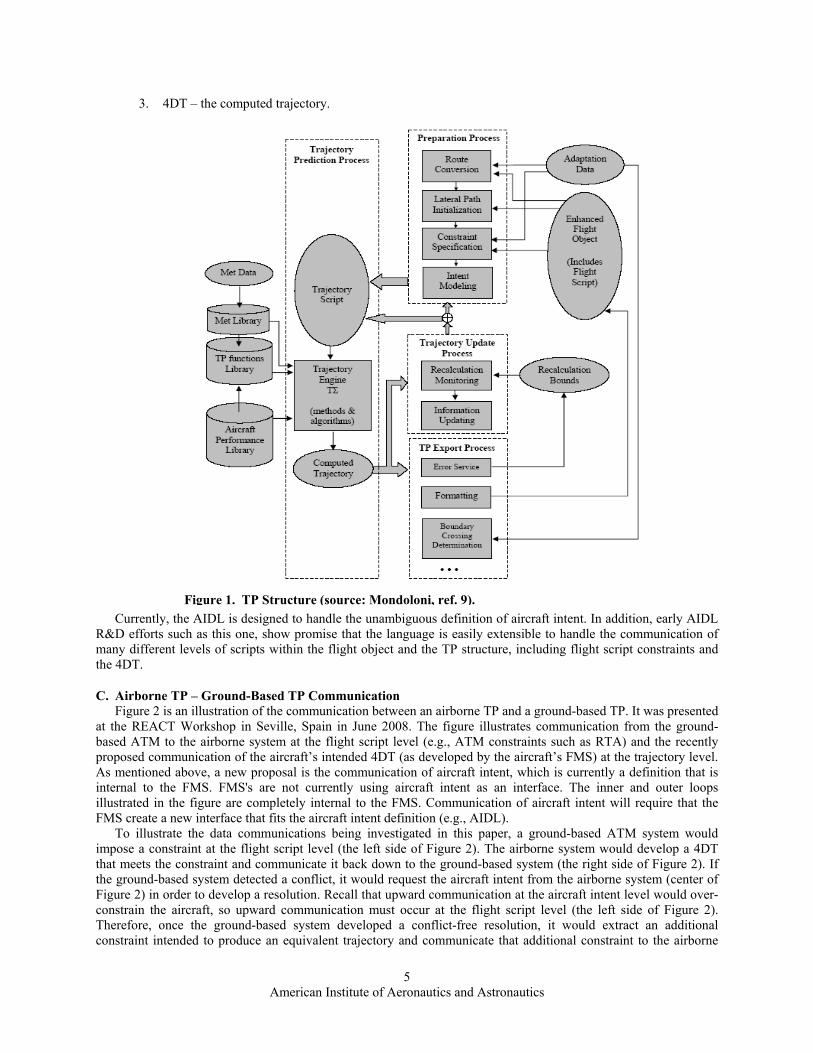
and NASA have all been involved in international workshops designed to minimize duplication of effort in reaching the goals of the future airspace system. The FAA/EUROCONTROL Action Plan 16 (AP 16) was organized in 2003 to establish common trajectory prediction capabilities. One of the outcomes of AP 16 was a definition of the common structure of a trajectory predictor as well as definitions of objects that identify aircraft intent at different levels of detail9. This document has helped to establish clear definitions of the TP structure and of the Flight Object. Fig. 3-1 of Mondoloni9 is repeated here as Figure 1. While this diagram and the associated definitions are currently being reviewed by AP 16, this document assumes the following associated definitions.
1. Flight Script – includes ATM imposed constraints, e.g., RTA, crossing restrictions. 2. Aircraft Intent – not defined in Figure 1. The output of the Preparation Process. Unambiguously defines
the aircraft trajectory.
American Institute of Aeronautics and Astronautics
5
3. 4DT – the computed trajectory.
Currently, the AIDL is designed to handle the unambiguous definition of aircraft intent. In addition, early AIDL
R&D efforts such as this one, show promise that the language is easily extensible to handle the communication of many different levels of scripts within the flight object and the TP structure, including flight script constraints and the 4DT.
C. Airborne TP – Ground-Based TP Communication Figure 2 is an illustration of the communication between an airborne TP and a ground-based TP. It was presented
at the REACT Workshop in Seville, Spain in June 2008. The figure illustrates communication from the ground-based ATM to the airborne system at the flight script level (e.g., ATM constraints such as RTA) and the recently proposed communication of the aircraft’s intended 4DT (as developed by the aircraft’s FMS) at the trajectory level. As mentioned above, a new proposal is the communication of aircraft intent, which is currently a definition that is internal to the FMS. FMS's are not currently using aircraft intent as an interface. The inner and outer loops illustrated in the figure are completely internal to the FMS. Communication of aircraft intent will require that the FMS create a new interface that fits the aircraft intent definition (e.g., AIDL).
To illustrate the data communications being investigated in this paper, a ground-based ATM system would impose a constraint at the flight script level (the left side of Figure 2). The airborne system would develop a 4DT that meets the constraint and communicate it back down to the ground-based system (the right side of Figure 2). If the ground-based system detected a conflict, it would request the aircraft intent from the airborne system (center of Figure 2) in order to develop a resolution. Recall that upward communication at the aircraft intent level would over-constrain the aircraft, so upward communication must occur at the flight script level (the left side of Figure 2). Therefore, once the ground-based system developed a conflict-free resolution, it would extract an additional constraint intended to produce an equivalent trajectory and communicate that additional constraint to the airborne
Figure 1. TP Structure (source: Mondoloni, ref. 9).

American Institute of Aeronautics and Astronautics
6
system. The airborne system would then develop a 4DT that met all constraints and communicate that 4DT down to the ground-based system. The airborne and ground-based systems would iterate through this process until a solution was obtained.
II. Interfacing TGF and AIDL
A. Aircraft Intent Description Language (AIDL) The AIDL is a formal language defined and developed by BR&TE10 to describe and exchange certain type of
trajectory related information: the aircraft intent. In the context of trajectory prediction, aircraft intent refers to the information that unambiguously describes how the aircraft is to be operated within a certain time interval. It is anticipated that sharing aircraft intent information expressed in a structured and formal manner (e.g., according to the AIDL) can facilitate the synchronization of the predicted aircraft trajectories held by different automation systems in the context of TBO6,11,12,13,14.
The AIDL is characterized by an alphabet and a grammar. The alphabet is formed by a set of instructions, which are conceptual elements used to model the basic commands, guidance modes or control strategies at the disposal of the pilot/FMS to direct the operation of the aircraft. They are used to close each of the degrees of freedom of the mathematical problem of the aircraft motion. The grammar contains both lexical and syntactical rules. The former govern the combination of instructions into words of the language, which are called operation, i.e., elemental behaviors elicited by the aircraft in response to the combination of instructions. The latter govern the concatenation of words into valid sentences, i.e. sequences of operations. The specification of these instructions according to the grammar rules allows for any real-time or fast-time simulator or trajectory generator to define and compute the aircraft flight unambiguously.
The definition of the alphabet and the grammar rules are based on a rigorous mathematical analysis of the trajectory computation process at the core of a TP, developed by Lopez15. This analysis relies on a novel approach to modeling the trajectory computation process based on the theory of Differential Algebraic Equations (DAEs). This approach proved that an aircraft intent formulated by means of the AIDL contains the necessary and sufficient
Figure 2. Communication Between Airborne and Ground-Based TPs (source: presentations by Miguel Vilaplana and Javier Lopez-Leones at REACT Workshop in Seville, Spain, 24-25 June 2008).
Data COM Infrastructure Predicted trajectory
TP PROCESS 1
Flight Intent
Airborne Predicted Trajectory
TP PROCESS 2
Flight Intent
Ground Predicted Trajectory
Trajectory Computation Infrastructure
(1)
Aircraft Intent
Intent Generation
Infrastructure (1)
Inner TP 1
Trajectory Computation Infrastructure
(2)
Aircraft Intent
Intent Generation
Infrastructure (2)
Inner
TP 2
Aircraft Intent
Outer
Outer
Flight Intent Information

American Institute of Aeronautics and Astronautics
7
information for the existence of a solution to the trajectory computation problem for any set of meaningful initial conditions. One of the benefits of the AIDL is that it provides operational insight into the trajectory that will be computed by the TP without the need of understanding the mathematics behind. As it will be shown below, the instructions of the AIDL capture in an intuitive way, basic modes of operating an aircraft, marrying on the one hand conventions used to describe procedures in ATM, and on the other hand the mathematics behind trajectory computation. The result is that, using the AIDL, a human or a machine can build up a sequence of aircraft intent without any knowledge of the underlying mathematics, leaving this responsibility to the dynamical model implemented in the TP to compute trajectories. The syntactical and lexical rules of the AIDL capture the underlying mathematics in a compact form and provide the means to ensure the correctness of the aircraft intent.
The AIDL instructions can influence any aspect of the aircraft motion (lateral motion, vertical motion, speed, energy, throttle and configuration settings) in very different ways. It is then up to the dynamics model reading the AIDL script to compute how the aircraft behavior is affected. Table 1 lists the 35 instructions present in the AIDL alphabet, known as ΣAIDL.
Set instructions model control and configuration transients. Typically, a set instruction captures the evolution of a state or configuration variable from an initial to a target value according to an externally defined function (e.g., the APM may define the transients of flap deployment).
Law instructions model closed-loop control and guidance laws. Typically, these instructions capture the evolution of a control or state variable as a function of one or more state variables (e.g., a law describing the evolution of the Mach number as a function of the altitude).
Hold instruction are simplified Law instructions. They describe situations where a desired motion or configuration variable is to be maintained constant. (e.g., hold altitude constant).
Open Loop instructions model direct commands of the pilot over the controls at his/her disposal.
Track instructions model guidance along a predefined geometry.
An instruction is characterized by a mathematical equation called the effect of the instruction, which is to be
satisfied simultaneously with the equations of motion during a certain time interval, denoted as the execution
Table 1. AIDL alphabet ΣAIDL (ref. 10).
American Institute of Aeronautics and Astronautics
8
interval of the instruction. Basically, the execution interval of an instruction indicates for how long this instruction is affecting the aircraft motion. The execution interval is defined by means of a begin and an end trigger, which respectively specify the conditions that define the starting and ending times of the execution interval. For instance, a HA instruction can finish when certain capture condition is reached (e.g., Mach number or path distance). In addition, these triggers admit the implementation of AND and OR logical operators to indicate complex conditions in which, for instance, the climbing at constant vertical speed (using a HVS, ends when either the aircraft reaches certain altitude OR has covered certain path distance.
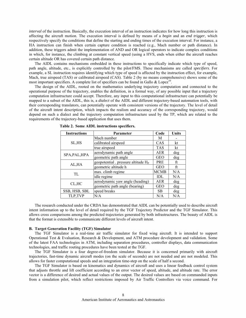
The AIDL contains mechanisms embedded in these instructions to specifically indicate which type of speed, path angle, altitude, etc., is explicitly controlled by the pilot/FMS. These mechanisms are called specifiers. For example, a SL instruction requires identifying which type of speed is affected by the instruction effect, for example, Mach, true airspeed (TAS) or calibrated airspeed (CAS). Table 2 (by no means comprehensive) shows some of the most important specifiers. A complete list of specifiers can be found in Gallo & Lopez10.
The design of the AIDL, rooted on the mathematics underlying trajectory computation and connected to the operational purpose of the trajectory, enables the definition, in a formal way, of any possible input that a trajectory computation infrastructure could accept. Therefore, any input to this computational infrastructure can potentially be mapped to a subset of the AIDL, this is, a dialect of the AIDL and different trajectory-based automation tools, with their corresponding translators, can potentially operate with consistent versions of the trajectory. The level of detail of the aircraft intent description, which impacts the realism and accuracy of the corresponding trajectory, would depend on such a dialect and the trajectory computation infrastructure used by the TP, which are related to the requirements of the trajectory-based application that uses them.
Table 2. Some AIDL instructions specifiers.
Instructions Parameter Code Units Mach number M - calibrated airspeed CAS kt SL,HS true airspeed TAS kt aerodynamic path angle AER deg SPA,PAL,HPA geometric path angle GEO deg geopotential . pressure altitude HP PRE ft AL,HA geometric altitude h GEO ft max. climb regime MCMB N/A TL idle regime IDL N/A aerodynamic yaw angle (heading) AER deg CL,HC geometric path angle (bearing) GEO deg
SSB, HSB, SBL speed breaks SB deg TLP,TVP N/A N/A N/A
The research conducted under the CRDA has demonstrated that AIDL can be potentially used to describe aircraft
intent information up to the level of detail required by the TGF Trajectory Predictor and the TGF Simulator. This allows cross comparisons among the predicted trajectories generated by both infrastructures. The beauty of AIDL is that the format is extensible to communicate different levels of aircraft intent.
B. Target Generation Facility (TGF) Simulator The TGF Simulator is a real-time air traffic simulator for fixed wing aircraft. It is intended to support
Operational Test & Evaluation, Research & Development, and ATM procedure development and validation. Some of the latest FAA technologies in ATM, including separation procedures, controller displays, data communication technologies, and traffic routing procedures have been tested at the TGF.
The TGF Simulator is a four degree-of-freedom simulator. Because it is concerned primarily with aircraft trajectories, fast-time dynamic aircraft modes (on the scale of seconds) are not needed and are not modeled. This allows for faster computational speeds and an integration time-step on the scale of half a second.
The TGF Simulator is based on kinematics and dynamics of aircraft and uses a linear feedback control system that adjusts throttle and lift coefficient according to an error vector of speed, altitude, and altitude rate. The error vector is a difference of desired and actual values of the output. The desired values are based on commanded inputs from a simulation pilot, which reflect restrictions imposed by Air Traffic Controllers via voice command. For

American Institute of Aeronautics and Astronautics
9
example, an Air Traffic Controller may command an aircraft to “descend and maintain flight level 230.” A simulation pilot would enter the command and the TGF control system would guide the aircraft to the desired value.
Many aircraft dynamic models with a feedback control system, such as the TGF Simulator, use the assumption of linear behavior in the immediate vicinity of a dynamic state. This implies that dynamic response (e.g., speed, altitude, and bank angle changes) to a control input (e.g., throttle, stick, and even wind gusts) in the vicinity of an equilibrium point (e.g., constant CAS climb) can be very closely modeled with linear behavior. Unfortunately, the linear model does not allow large error vectors because they lead to extreme control maneuvers. In response, TGF developers created regions within an aircraft’s flight envelope in which the assumption of linear behavior remains reasonably accurate. The TGF Simulator currently divides an aircraft’s flight envelope into 16 regions and simulated pilot logic (e.g., a maneuver) is applied to guide the aircraft between regions until the desired state is reached.
The reader is referred to Peters & Konyak2 for details of the TGF Simulator.
C. TGF Trajectory Predictor The TGF TP uses the same equations of motion as the TGF simulator. The difference is that there is no control
system; the TGF TP assumes that the vertical, lateral, and speed profiles are followed exactly so there is no need for a control system to maintain path or guide the aircraft to the path. The reader is referred the Konyak & Lykens16 for details of the TGF TP.
Because of the absence of a dynamic controller, the TGF TP is perfectly suited for interfacing with AIDL. In fact, the TGF TP was designed with AIDL in mind. This allows identical instructions, identical instruction intervals, and a variable integrator that changes according to the needs of the aircraft dynamic state. When the path constraints reduce the equations of motion to linear dynamics, a simple, first-order integrator is used. When the equations of motion remain non-linear (e.g., CAS descent over a variable heading course), a fourth-order Runge-Kutta integrator is selected. The time step also varies according to the needs of the dynamics, from 10 seconds to 500 seconds. These two techniques allow extremely fast trajectory computations.
D. Mapping TGF Speed-Altitude Maneuvers to AIDL Instructions The TGF Simulator has longitudinal maneuvers that map directly to AIDL longitudinal instructions.
Additionally, TGF lateral maneuvers are virtually identical to AIDL lateral instructions. This mapping is illustrated in this section.
TGF Speed-Altitude Maneuvers include Constant CAS Climb/Descent, Constant Mach Climb/Descent, Level (i.e., constant altitude) Acceleration, Level Deceleration, Level Wait (cruise at a constant speed and altitude until a specified time or distance from a fix), No Change (cruise indefinitely), Landing Ground Run, Takeoff Ground Run, Rotation (before takeoff), Landing Flare, Constant Flight Path Angle Climb/Descent, and ILS Descent.
The AIDL configuration instructions do not have direct corollaries in the TGF Simulator. Aircraft flap settings, speed brakes, and landing gear are set according to specific algorithms internal to the simulator. They are not accessible to TGF simulation pilots or to the Air Traffic Controllers. The closest corollary is to the TGF “Expedite” maneuvers, in which the simulator may set aircraft drag devices in order to create more drag in a descent. 1. AIDL Hold Instructions
HS – The TGF Simulator maintains constant CAS or Mach via the Level Wait Maneuver, the No Change Maneuver, the CAS Climb/Descent Maneuvers, the Mach Climb/Descent Maneuvers
HHS – The TGF Simulator converts a desired ground speed to Mach or CAS and maintains constant CAS or Mach via the Level Wait Maneuver, the No Change Maneuver, the CAS Climb/Descent Maneuvers, the Mach Climb/Descent Maneuvers
HVS – The TGF Simulator contains a Constant Vertical Speed Maneuver in which a commanded vertical speed is maintained.
HE – The TGF Simulator maintains constant variation between kinetic and potential energy during simultaneous changes in speed and altitude that are directly analogous to the hold energy instruction.
HPA - TGF Simulator maintains constant path angle via the Flight Path Angle Descent Maneuver and the ILS Approach Maneuver
HA – The TGF Simulator maintains constant altitude via the Level Wait Maneuver, the No Change Maneuver, the Level Deceleration Maneuver, and the Level Acceleration Maneuver.
HT – The TGF Simulator contains maneuvers that specify the thrust coefficient as a constant value. Currently, those constant values correspond to idle throttle and maximum climb throttle.
HBA – The TGF Simulator will maintain a constant bank angle during certain turn maneuvers. HC - TGF Simulator maintains constant course via the Heading Maneuver.

American Institute of Aeronautics and Astronautics
10
HHL – The TGF Simulator models the high lift devices as discrete values and they are held constant over an interval.
HSB – The TGF Simulator models the speed brakes as a Boolean value that is either on or off over an interval. HLG – The TGF Simulator models the landing gear as a Boolean value that is either on or off over an interval.
2. AIDL Set Instructions ST – The TGF Simulator has engine spooling lag built into the engine dynamics to simulate throttle variation
from the current value to the targeted value. SPA – The TGF Simulator has no need for a corresponding instruction. The feedback control system
manipulates throttle and lift coefficient to obtain target state values and the path angle variation is defined by those dynamics.
SBA – The TGF Simulator uses bank angle dynamics to target a specific bank angle. SHL – The TGF Simulator does not model the transition of high lift devices between settings. The high lift
device settings are discrete functions with five settings from a clean configuration (for cruise) to a full extension configuration (for landing).
SSB - The TGF Simulator does not model the transition of speed brakes. They are modeled with a discrete function that is either on or off.
SLG - The TGF Simulator does not model the extension and retraction of landing gear. They are modeled with a discrete function that is either on or off. 3. AIDL Law Instructions
TL– The TGF Simulator has maximum thrust and idle thrust controllers in which the thrust is not controlled but is allowed to varying with altitude (and speed, in the case of turboprop and piston aircraft).
SL – On aircraft approach, the TGF will guide the aircraft through a preferred speed-altitude profile based on the perceived distance from the runway threshold. Other than that, the TGF Simulator does not currently have a need for varying speed as a function of some independent parameter.
HSL – The TGF Crossing Maneuver will adjust aircraft speed based on the measured close rate to a fix. This is a form of a horizontal speed law.
VSL – The TGF Simulator has a Flare Maneuver on Landing that adjusts altitude rate as a function of altitude above the runway.
EL – The TGF Simulator does not currently have a need for varying energy as a function of some independent parameter.
AL – Hold path angle is a form of an altitude law. Also, on aircraft approach, the TGF will guide the aircraft through a preferred speed-altitude profile based on the perceived distance from the runway threshold. Other than that, the TGF Simulator does not currently have a need for varying speed as a function of some independent parameter.
PAL – The TGF Simulator does not currently have a need for varying path angle as a function of some independent parameter.
CL – The TGF Route Follow, Route Offset, and Ground Track Maneuvers are forms of varying course (heading) as a function of position.
HLL – The TGF Simulator contains internal rules for setting the high lift devices during takeoff and landing maneuvers (e.g., ILS Approach Maneuver)
SBL – The TGF Simulator contains internal rules for turning speed brakes on and off during the Crossing Maneuver and Landing Maneuver.
LGL – The TGF Simulator contains internal rules for extending and retracting landing gear based on distance from the runway threshold and aircraft speed and altitude during takeoff and landing maneuvers. 4. AIDL Open Loop Instructions
Open Loop instructions for flight path angle, throttle, bank angle, and speed brakes are not currently used in the TGF Simulator. 5. AIDL Track Instructions
TVP– The TGF Simulator tracks a vertical path via the Follow Track Maneuver. TLP– The TGF Simulator tracks a lateral path via the Route Follow, Follow Track, Ground Track, and Hold
Maneuvers.
E. Interfacing TGF with AIDL – Implicit and Explicit AIDL As has been shown, many AIDL commands map directly to TGF Speed-Altitude Maneuvers and Lateral
Maneuvers. However, an AIDL Reader is still required as the interface. The AIDL Reader reads AIDL instructions

American Institute of Aeronautics and Astronautics
11
and transforms the complete aircraft intent to a TGF flight plan file. The reader is referred to Konyak and Lykens16 for further detail.
In some cases, the AIDL Reader is insufficient for transforming to a TGF flight plan file. These cases are those in which AIDL "Auto Parameters" are defined. These are the parameters which are left as unknown or unspecified. The aircraft intent is still unambiguous, as proven in Vilaplana and Lopez10, but the aircraft intent takes an "implicit" form. The TGF is describing such aircraft intent files as Implicit AIDL. As an example, an aircraft that wishes to maintain a constant calibrated airspeed through the cruise and descent phases but wishes to cross a fix at a given altitude could use an AIDL auto-parameter in its instructions. The TOD is unspecified, but the aircraft intent is still unambiguous. The TGF has called this an Implicit AIDL. If the AIDL-generating tool chooses to not use an auto-parameter and instead explicitly state the TOD, the TGF would call this an Explicit AIDL.
Explicit AIDL can be read directly by the TGF's AIDL Reader and transformed into TGF Speed-Altitude Maneuvers and Lateral Maneuvers. Implicit AIDL would require the generation of an equivalent Explicit AIDL by the TGF TP. Each form of the AIDL is an unambiguous definition of the same aircraft intent.
The advantage of Implicit AIDL is that it is independent of the aircraft model and the weather model. If the weather model is updated after the aircraft intent has already been communicated, the Implicit AIDL needs to be changed only if the FMS (or other aircraft intent generating tool) deems it necessary. However, it is recognized here that it is standard ATM procedure for the aircraft intent to be re-issued if any of the TP structure models change. In that case, it is not necessary to have Implicit AIDL because the benefit is lost and it would only create more work for the TP receiving the AIDL.
III. Method - Demonstrating Aircraft Intent Communication
A. Revisiting a 17-Year-Old Study As a demonstration of the communication of aircraft intent via AIDL and how it plays a role in ensuring conflict-
free trajectories, we have designed simulated flights similar to those used in the research of Williams and Green5. The simulated flights of Williams and Green were approaches into the Denver area for two aircraft of the same type (Boeing 737-100). Each aircraft began at a point 210 nautical miles (nm) out of Denver at an altitude of 31,000 feet and Mach # of 0.74. The aircraft were to begin and end the simulation with 80 seconds of separation, but the only constraint put on the flights was an RTA to the metering fix at 80 seconds apart. The altitude and speed at the metering fix were the same for each aircraft: 11,000 feet and 210 knots. The only other difference was that the two aircraft were modeled to have selected different speed strategies to meet the RTA.
The leading aircraft selected speeds in a manner similar to the ATC Descent Advisor program. This speed strategy is designed to provide consistent final conditions for aircraft delivered to the metering fix. This method allows a variety of aircraft types to be merged on final en route descent at a common speed for handoff to the terminal area controllers. The trailing aircraft selected speeds based on a cost index intended to optimize time and fuel. This was called the Minimum Fuel Strategy. This strategy was intended to model a profile generated by a 4D-capable FMS onboard the trailing aircraft. The essential difference was in the cruise speed and descent speed selected to meet the requirements of the speed strategy.
Williams and Green showed that the speeds selected by the different strategies were the same only when the time constraint imposed on the speed strategy resulted in selection of the same cruise and descent speed for the two aircraft – i.e., a Mach 0.72 cruise and a 280 knot descent. As the time constraint got shorter, the in-trail separation increased during the cruise phase and closed back up during the descent. As the time constraint got longer, the in-trail separation shrunk during the cruise phase, enough, in some cases, that the Minimum Fuel aircraft overtook the ATC Descent Advisor aircraft. Williams and Green highlighted the case of the greatest conflict and we will emulate that experiment here.
B. Experiment Design Figure 3 shows the approach route used in our scenario: The GOLDN4 Standard Terminal Arrival Route
(STAR) in the San Francisco Airport (SFO) terminal area. It was chosen for its similarity to the Denver scenario of Williams and Green. The aircraft were instantiated at the FOT fix 80 seconds apart and were given 36 minutes to reach the metering fix. To be consistent with a real air traffic scenario, let us assume that each aircraft is given an RTA to the metering fix with an altitude constraint of 11,000 ft, a speed constraint of 210 KIAS, and time constraints 80 seconds apart, intended to maintain the spacing. Let us also assume that the ATM system requires that the aircraft respond to the consecutive RTAs with aircraft intent scripts via AIDL to define their trajectories unambiguously.

American Institute of Aeronautics and Astronautics
12
Figure 3. Simulation scenario showing the modeled approach route along the GOLDN4 STAR.
Figure 4. Predicted and Actual Trajectories for Boeing 737-200 using ATC Descent Advisor Profile.

American Institute of Aeronautics and Astronautics
13
At this point, we assume that the leading aircraft selects a speed profile consistent with the ATC Descent Advisor program that meets the given RTA. This profile is a Mach 0.62 cruise for about 150 nm and a 280 KIAS descent, with a TOD about 70 nm from the metering fix. Figure 4 shows the profile chosen by the leading aircraft. The ground-based system would have the capability to regenerate the unambiguous trajectory. This is demonstrated by use of the TGF TP, the "predicted" line in Figure 4. We use the term "regenerate" because it is assumed that the unambiguous trajectory was generated by the airborne FMS and communicated via AIDL to the ground-based system.
Figure 4 also shows an "actual" trajectory. This is created with the TGF Simulator for comparison to the TGF TP. Upon generating the aircraft intent, the TGF TP can communicate the flight plan to the TGF Simulator via the TP/Simulator interface. Alternatively, the TGF Simulator's AIDL Reader can serve as the interface to AIDL. The comparison via error metrics will be discussed later.
The trailing aircraft in our simulation is assumed to have selected a minimum fuel speed profile that meets the given RTA. It should be noted that no cost index optimization was used in this study. We merely assumed that the Cruise Mach/Descent CAS pairs used by Williams and Green would produce minimum fuel approaches. The profile is a Mach 0.68 cruise for about 140 nm and a 230 KIAS descent, with a TOD about 80 nm from the metering fix. Figure 5 shows the profile chosen by the trailing aircraft. Once again, the ground-based system would have the capability to regenerate the unambiguous trajectory. This is demonstrated by use of the TGF TP, the "predicted" line in Figure 5. Figure 5 also shows an "actual" trajectory. This is created with the TGF Simulator for comparison to the TGF TP. The comparison via error metrics will be discussed later.
C. Results of the Emulated Experiment Figure 6 demonstrates the separation conflict generated by the different speed profiles used by the aircraft-in-
trail during the approach. This illustrates that, even though the aircraft start and end with 80 seconds of in-trail separation, the issuance of an RTA to aircraft-in-trail is not sufficient for conflict-free trajectories.
Figure 5. Predicted and Actual Trajectories for Boeing 737-200 using Minimum Fuel Profile.

American Institute of Aeronautics and Astronautics
14
A ground-based CD&R tool analyzing the aircraft intent and corresponding trajectories of these aircraft would
recognize the conflict. There are an infinite number of solutions to this conflict and there are numerous variables to consider, including path stretching and other aircraft in the near airspace. It cannot be known what solution will be chosen by an individual CD&R. CD&R tools currently under development, in responding to the promise of the communication of aircraft intent, are expecting to be able to generate a conflict-free trajectory given all known parameters and communicate that to one of the aircraft in conflict. As stated earlier, this is not a desirable solution because a ground-based CD&R tool cannot optimize the performance of individual aircraft and individual aircraft will not want to be so constrained.
It may be a better solution for the ground-based CD&R tool to propose an additional constraint to one of the aircraft and to pass that up to the aircraft through the DATACOM structure (i.e., the left side of Figure 2). It should be noted here that AIDL is easily extensible to facilitate such communication. The airborne FMS would then generate a new aircraft intent or 4DT and communicate that back down to the ground. There is expected to be some iteration on this process until a conflict-free resolution is reached. Research that investigates this loop iteration is planned as part of the FAA/Boeing CRDA.
IV. Results – Comparing TGF TP and TGF Simulator Figure 7 and Figure 8 illustrate the error metrics for the two aircraft in trail. The "errors" of each figure are the
differences in the respective values of the predicted trajectory of the TGF TP and the actual trajectory of the TGF Simulator. The metrics are commonly accepted TP metrics. The reader is referred to Mondoloni, et. al.,11 for a more detailed description of the metrics.
The cross-path error is always positive and so does not indicate the direction of the error. It is, however, never more than 0.08 nm or about 500 ft. The mean cross-path error is on the order of 100 ft. The predominant source of cross-path error is probably due to two reasons: the TGF TP does not model flight technical error (it assumes the lateral path is held exactly) and it does not model roll-in and roll-out when turning (it assumes constant radius turns).
Figure 6. Separation conflict induced by dissimilar speed strategies (data points plotted every 40 seconds).

American Institute of Aeronautics and Astronautics
15
Figure 8. TP Error Metrics for Boeing 737-200 using Minimum Fuel Profile.
Figure 7. TP Error Metrics for Boeing 737-200 using ATC Descent Advisor Profile.

American Institute of Aeronautics and Astronautics
16
The altitude error is very small during the cruise phase of flight and is highest at the transitions between level flight and descending flight. Altitude errors on the descent phase of the ATC Descent Advisor aircraft are too big to be of use to a CD&R tool but the overall speed and time errors are suitable for use in currently proposed TGF applications. It is expected that most of the altitude error is due to the TGF TP's not modeling descent transitions. The Minimum Fuel aircraft's altitude error is smaller during descent transition and during the descent. This is because the Minimum Fuel AIDL is modeling the descent transition with a HE (Hold Energy) instruction which is a more accurate transition model.
The time error gets worse with simulation time, a common problem with TP tools. We see that in our 36 minute simulations, the time error grows to about 6 seconds. Again, this is probably insufficient for reliable conflict detection and resolution, but is suitable for currently proposed TGF applications.
The speed error is overall very low but spikes just above 5 knots during level flight/descent flight transitions. Once again we see that the Minimum Fuel aircraft's modeling of the descent transition via an AIDL HE instruction creates a more accurate representation of the transition. And a 5-knot error is well within the acceptable range of current TGF applications.
These plots of TP error metrics illustrate a very important detail. Reliable ground-based CD&R will require TP accuracy within about two seconds over a 20-minute trajectory. Both of the flights simulated here have about a four-second error at the 20-minute mark. Improvement on the accuracy of the TGF TP would require accurate modeling of turn and descent transitions. In addition, the mass of the aircraft (as affected by the fuel burn model) has a large effect on the 20-minute trajectories and needs to be carefully modeled.
V. Conclusions This paper has demonstrated the use of AIDL in communicating aircraft intent between airborne and ground-
based trajectory predictors. It was shown that the AIDL is easily extensible to communicate 4D trajectories and ATM-imposed constraints (at the flight script level). Communication of aircraft intent is necessary for ground-based CD&R tools to perform a conflict resolution function.
This study repeated the finding that a ground-based ATM-imposed time constraint (RTA) is insufficient for ensuring conflict-free trajectories and a that a 4DT alone is insufficient for a ground-based CD&R tool to perform effective conflict resolution because the aircraft's intent cannot be extracted.
This study demonstrated the feasibility of the communication of ATM-imposed constraints to an airborne system via AIDL. The FAA William J. Hughes Technical Center's TGF TP was used to emulate the airborne FMS. The TGF's real-time aircraft simulator was used to simulate actual flight. The simulations demonstrated that AIDL was successful at communicating airborne FMS-developed aircraft intent, and is easily extensible to communicate ground-based ATM-imposed constraints and airborne FMS-developed 4D trajectories. The simulations demonstrated the TGF TP was able to predict the simulated aircraft trajectory with a maximum along-track error of 6 seconds, a maximum cross-track error of 0.08 nm, a maximum vertical error of 300 ft, and a maximum absolute position error of 8 nm.
Acknowledgments The authors wish to thank the staffs of Boeing Research & Technology Europe and the FAA Target Generation
Facility for their support of the research and development for this study. The authors acknowledge Robert Vivona and Stephen DiPascale for their contribution in developing tools for creating the general trajectory and error graphs used in the analysis of the results of this study. M. A. Konyak also wishes to thank Mike Paglione of the FAA William J. Hughes Technical Center for his continued insight and guidance and for providing the motivation for this study.

American Institute of Aeronautics and Astronautics
17
References
1 "Concept of Operations for the Next Generation Air Transportation System Version 2.0," Joint Planning and Development Office, 13 June 2007.
2 Peters, M., and Konyak, M. A., "The Engineering Analysis and Design of the Aircraft Dynamics Model for the Target Generation Facility," Federal Aviation Administration William J. Hughes Technical Center, AJP-7860, November 2003 (unpublished).
3 "Research and Development Plan for the Next Generation Air Transportation System, FY 2009 – FY 2013," Joint Planning and Development Office, 31 August 2007.
4 "FAA's NextGen Implementation Plan, Overview 2008," Federal Aviation Administration, Washington, D.C., June 2008 5 Williams, D. H., Green, S. M., "Airborne Four-Dimensional Flight Management in a Time-Based Air Traffic Control
Environment," NASA TM 4249, 1991 6 Vilaplana, M. A., Gallo, E., Navarro, F. A., and Swierstra, S., "Towards a Formal Language for the Common Description of
Aircraft Intent," 24th Digital Avionics Conference, 0-7803-9307-4/05, 2005 7 Wing, D. J; Ballin, M. G; Krishnamurthy, K., "Pilot In Command: A Feasibility Assessment of Autonomous Flight
Management Operations," 24th International Congress of the Aeronautical Sciences, Yokohama, Japan, 2004 8 Prevot, T.; Lee, P.; Smith, N.; Palmer, E., "ATC Technologies for Controller-Managed and Autonomous Flight
Operations," 2005 AIAA Guidance, Navigation, and Control Conference and Exhibit, San Francisco, Aug. 2005 9 Mondoloni, S., "Flight Object - A Recommendation for Flight Script and Trajectory Description," FAA/EUROCONTROL
Action Plan 16, (unpublished). 10 Gallo, E., and Lopez-Leones, J., "Aircraft Intent Description Language (AIDL) Specification v1.1," BRTE-ATT0725-
AIDK1100-SPEC, Boeing Research & Technology Europe, 28 September 2007. 11 Mondoloni, S., Swiestra, S., and Paglione, M., "Assessing Trajectory Prediction Performance – Metrics Definition," 24th
Digital Avionics Systems Conference, Washington, DC, October 2005. 12 Mondoloni, S., and Swierstra, S., "Commonality in Disparate Trajectory Predictors for Air Traffic Management
Applications," 24th Digital Avionics Systems Conference, Washington, DC, October 2005. 13 Garcia-Avello, C., Idris, H., Vivona, R., and Green, S., "Common Aircraft Performance Modeling Evaluation Tools and
Experiment Results," 24th Digital Avionics Systems Conference, Washington, DC, October 2005. 14 Paglione, M., Garcia-Avello, C., Swierstra, S., Vivona, R., and Green, S., "A Collaborative Approach to Trajectory
Modeling Validation," 24th Digital Avionics Systems Conference, Washington, DC, October 2005. 15 Lopez-Leones, J., "Definition of an Aircraft Intent Description Language for Air Traffic Management Applications,"
Ph.D. dissertation, Department of Aerospace Engineering, University of Glasgow, February 2008. 16 Konyak, M., and Lykens, J., "The Engineering Design of the Target Generation Facility Trajectory Predictor", Federal
Aviation Administration William J. Hughes Technical Center, AJP-7860, November 2008 (unpublished).