A CRITICAL ANALYSIS OF THE GATESHEAD … CRITICAL ANALYSIS OF THE GATESHEAD MILLENIUM BRIDGE ......
10
A CRITICAL ANALYSIS OF THE GATESHEAD MILLENIUM BRIDGE T.O. Butler 1 1 Undergraduate Student – University of Bath Abstract: This paper gives a critical analysis of the Gateshead Millennium Bridge, which sits between Gateshead and Newcastle upon Tyne, UK. The world‟s only tilting bridge, basic structural analysis is undertaken to British Standard BS5400:2-2006 to establish loading and basic structural capacity, understand the how the structure works , its efficiency and how all this changes when tilted. The Leonhardt Method of aesthetic analysis is applied to explore the bridges appearance, and additional aspects attributed to the design including construction, geology, serviceability, dynamic stability and durability are also discussed. Keywords: Gateshead, Millennium, Bridge, Arch, Steel, Tilting 1 Introduction The Gateshead Millennium Bridge (Fig.1) is a tilting, arch bridge. It was the winning entry of a design competition set by Gateshead Council to create a bridge that spans the river Tyne from Newcastle‟s Quayside to the Gateshead Quays and cost £22 million [1]. The entry was submitted by consulting engineers Gifford and Partners with Wilkinson Eyre architects. The brief was to create an iconic structure - a symbol of the regions, and immediate areas, prosperity and continued development. It primarily serves as a link between Newcastle‟s trendy bar, restaurant & hotel scene and Gateshead‟s „art quarter‟, including the renovated flour mill - the Baltic Gallery. Recently the Sage (Fig.2), a music and conference venue, has taken residence in this „art quarter‟. Both the Baltic and the Sage are significant structures in their own right, which has added pressure for the bridge to perform aesthetically as well as structurally. The Quayside has historically been shrouded in industry. A lot of the old warehousing has been either demolished and built on or just converted into a range of upscale commercial & residential premises. On the Gateshead side this involved the conversion of the Baltic flour mill into a contemporary art gallery. On the Newcastle side a good example is the old Co-operative warehouse, which is now an upscale Mal Maison hotel, which sits just off the northern end of the bridge. As well as fitting in with structures either side of the river, the bridge also had to compliment the rivers existing bridges. The six bridges all sit parallel along a straight stretch of the river and include some of the most iconic and notable bridges in the world - the Tyne bridge being the foremost. It is obvious from first impression that this bridge has influenced the design of the Gateshead Millennium Bridge, most notably in its sweeping arch. Fig.3 illustrates this. Other significant bridges include Robert Stephenson‟s High Level Bridge, a recently refurbished double-decker bow- string girder bridge carrying both cars and the East Coast Mainline railway, and the Swing Bridge designed and paid for by Lord William Armstrong - the only other crossing at quayside-level. It was very important that these structures, steeped in history, weren‟t undermined or indeed overshadowed by the new bridge. A challenge of the bridge was to both to allow quayside-level crossing and yet also achieve enough clearance underneath for all manner of river traffic, including a large Royal Navel patrol vessel moored a hundred yards upstream at HMS Calliope, a Royal Naval Reserve Centre. In some respects these Proceedings of Bridge Engineering 2 Conference 2011 April 2011, University of Bath, Bath, UK Figure 1: The Gateshead Millennium Bridge [6] Figure 2: The Sage [6] 1 Mr. T.O.Butler – [email protected]
Transcript of A CRITICAL ANALYSIS OF THE GATESHEAD … CRITICAL ANALYSIS OF THE GATESHEAD MILLENIUM BRIDGE ......

A CRITICAL ANALYSIS OF THE GATESHEAD MILLENIUM BRIDGE
T.O. Butler1
1Undergraduate Student – University of Bath
Abstract: This paper gives a critical analysis of the Gateshead Millennium Bridge, which sits between
Gateshead and Newcastle upon Tyne, UK. The world‟s only tilting bridge, basic structural analysis is
undertaken to British Standard BS5400:2-2006 to establish loading and basic structural capacity, understand
the how the structure works , its efficiency and how all this changes when tilted. The Leonhardt Method of
aesthetic analysis is applied to explore the bridges appearance, and additional aspects attributed to the design
including construction, geology, serviceability, dynamic stability and durability are also discussed.
Keywords: Gateshead, Millennium, Bridge, Arch, Steel, Tilting
1 Introduction
The Gateshead Millennium Bridge (Fig.1) is a
tilting, arch bridge. It was the winning entry of a design
competition set by Gateshead Council to create a
bridge that spans the river Tyne from Newcastle‟s
Quayside to the Gateshead Quays and cost £22 million
[1]. The entry was submitted by consulting engineers
Gifford and Partners with Wilkinson Eyre architects.
The brief was to create an iconic structure - a symbol
of the regions, and immediate areas, prosperity and
continued development. It primarily serves as a link
between Newcastle‟s trendy bar, restaurant & hotel
scene and Gateshead‟s „art quarter‟, including the
renovated flour mill - the Baltic Gallery. Recently the
Sage (Fig.2), a music and conference venue, has taken
residence in this „art quarter‟. Both the Baltic and the
Sage are significant structures in their own right, which
has added pressure for the bridge to perform
aesthetically as well as structurally.
The Quayside has historically been shrouded in
industry. A lot of the old warehousing has been either
demolished and built on or just converted into a range
of upscale commercial & residential premises. On the
Gateshead side this involved the conversion of the
Baltic flour mill into a contemporary art gallery. On the
Newcastle side a good example is the old Co-operative
warehouse, which is now an upscale Mal Maison hotel,
which sits just off the northern end of the bridge.
As well as fitting in with structures either side of
the river, the bridge also had to compliment the rivers
existing bridges. The six bridges all sit parallel along a
straight stretch of the river and include some of the
most iconic and notable bridges in the world - the Tyne
bridge being the foremost. It is obvious from first
impression that this bridge has influenced the design of
the Gateshead Millennium Bridge, most notably in its
sweeping arch. Fig.3 illustrates this. Other significant
bridges include Robert Stephenson‟s High Level
Bridge, a recently refurbished double-decker bow-
string girder bridge carrying both cars and the East
Coast Mainline railway, and the Swing Bridge
designed and paid for by Lord William Armstrong - the
only other crossing at quayside-level. It was very
important that these structures, steeped in history,
weren‟t undermined or indeed overshadowed by the
new bridge.
A challenge of the bridge was to both to allow
quayside-level crossing and yet also achieve enough
clearance underneath for all manner of river traffic,
including a large Royal Navel patrol vessel moored a
hundred yards upstream at HMS Calliope, a Royal
Naval Reserve Centre. In some respects these
Proceedings of Bridge Engineering 2 Conference 2011
April 2011, University of Bath, Bath, UK
Figure 1: The Gateshead Millennium Bridge [6]
Figure 2: The Sage [6]
1 Mr. T.O.Butler – [email protected]

limitations have all contributed lead to the final
solution of a tilting bridge.
2 Aesthetics
The concept of a bridge that moves in order to
allow river traffic through is not a new one, the
drawbridge probably being the earliest example. The
Victorians developed swing bridges using mechanical
machinery developed during the industrial revolution –
there is an example of one on the river Tyne. Areas like
Norfolk, heavily laden with waterways, also host a
decent population of these bridges. Other popular
moving bridge types include bascule, folding,
retractable, lifting and transporter bridges. However the
Gateshead Millennium Bridge is the first and still the
only bridge in the world to tilt.
Aesthetics play a huge part in the bridge choice,
of the selection of moving bridges listed above, not
many offer any design potential for a striking,
architectural structure likely to capture the hearts and
minds of the local population. In some respects, the
concept of a tilting bridge was the ultimate solution.
2.1 Fritz Leonhardt Analysis
Aesthetic evaluation of bridges is a contentious
issue in engineering. Many academics have published
work on the aesthetic analysis of bridges, however
these generally tend to conflict with each other as the
analysis is too subjective and down to personal taste.
Fritz Leonhardt is widely regarded as one of the most
important bridge engineers of the past century, and his
rules on aesthetics break down into ten categories and
are appreciated as a more objective approach to
aesthetic analysis.
2.1.1 Fulfillment of function
In terms of revealing the structure, the Gateshead
millennium bridge is structurally honest. Its inclined
parabolic arch clearly supports the deck, whilst its
chunky abutments, which house the hydraulic rams,
top the arch from splaying. In the tilted position the
bridge looks well balanced and sturdy (Fig.8).
2.1.1 Proportions of the bridge
The proportions of the bridge have been given
much thought. The arch is of the same depth/span ratio
as the Tyne Bridge it sits up stream of (Fig.3); this
compliments the existing structure and helps the two
coexist together. The main arch itself is tapered, getting
broader towards the base (Fig.4), proportional to the
forces through it. The deck is substantially bigger than
the arch supporting it, however the arches inclination
against the deck compensates for this.
2.1.3 Order within the structure
As an arch, the bridge has no significant edges or
lines, the hangers are well positioned evenly apart and
hang perpendicular to the plate of the kite-shaped arch,
the cables don‟t cross each other. This gives the bridge
excellent order.
2.1.4 Refinement of design
This bridges detailing is very contemporary, both
in the finishing of the deck and its components. The
kite-shaped section of the arch (Fig.4) with its flat,
aerodynamic surface and shape, combined with its
discreet tapering and broadening towards the base give
the bridge create a sense of quality engineering and
performance. This improves the image of the bridge
both from it looking stronger and more beautiful.
2.1.5 Integration into the environment
Figure 3: Tyne Bridges [6]
Figure 4: The main Arch [6]

It was always important for the bridge to fit in
with the new, modern and trendy surrounding of the
Quayside. It does this seamlessly with its bold and
contemporary architecture and particularly with its
location. It arrives directly in front of the Baltic, almost
as if it were a piece of exhibited art itself for the
gallery.
2.1.6 Surface texture
The bridge is made from steel, and is shot blasted
and paint finished. It is smooth and clean, giving the
arch and deck a very sharp, crisp and modern look. The
deck subtlety uses different paving surfaces for both
the pedestrian and lower cycling sections – dark, gritty
asphalt for the pedestrians and the light, smooth timber
decking for the cyclist.
2.1.7 Colour of components
In all the images featured, the white finish gives a
light and visually pleasing feel to the bridge. Fig.4
particularly demonstrates how the light colour contrasts
with shadows created to accentuate the slenderness and
beauty of the arch. The hangers, although not painted,
are very thin and blend into the skyline, helping draw
attention to the arch.
2.1.8 Character
Perhaps the most subjective of Leonhardt‟s
categories, character is hard to define. The author
would certainly say that this bridge is steeped in
character. It is a sleek, contemporary alternative to the
existing Tyne Bridge, contrasting its complex parabolic
truss arch and towering masonry abutments. The
people of Tyneside love their new bridge so much
they‟ve put it on their beer – testament to the character
this bridge bestows.
2.1.9 Complexity
The arch is no new concept, and despite the arch
being inclined and the forces from the stays not acting
in plane with the parabola, it is still reasonably simple
to deduce how the structure works.
2.1.10 Incorporation of nature.
Nature is a difficult thing to incorporate into a
structure in such a built up and urbanised area. Certain
features of the bridge, such as its stainless steel „hedge‟
partition for the pedestrians and cyclists draw on ideas
from nature – using a broader, more solid looking
barrier than just a fence, to separate the two. Most
importantly, the movement of the bridge has been
likened to a „blinking eye‟ – the local nick-name for the
structure. This almost poetically links in with it being a
symbol of the eye-opening development of the area.
3 Structural Design
The bridge is an inclined 2-pin arch. It is difficult
to judge whether or not the arch is tied. The deck is
Figure 5: The Bridge set against the Baltic Gallery [6]
Figure 6: Bridge Deck [6]
Figure 7: Newcastle Brown Ale label featuring the bridge
Figure 8: Bridge when tilted [6]

curved, so carrying the lateral forces through it is
naturally going to want to straighten and buckle the
deck. Also, during construction, a temporary tie is used
to prevent splaying of the arch [2].
Therefore, although a proportion of the horizontal
load probably is taken axially through the deck, for
simplicity of analysis I will assume it is untied and all
lateral loading is taken by the abutments. When the
bridge is tilted, it becomes a butterfly arch, with the
cables sitting horizontally, taking some of the self-
weight of the deck arch back into the main arch.
3.1 Structural Components
The structure is almost completely constructed
from steel. The main arch is kite-shaped in section,
which doubles in size between the base and the apex of
the arch. The steel plates used for fabrication are 35mm
thick, with an array of lateral and longitudinal internal
stiffeners running through the length of the arch [1].
The arch is 45m above river level and spans 105m. It is
inclined at ~15˚ to the vertical, supports the deck from
18 galvanized steel stay cables, anchored into the arch.
The decks prime reason for curvature is to add an
additional 30% length to the deck [1], which allows for
the desired ramp gradient to be maintained whilst also
achieving the required clearance of 4.5m above river
level. This allows the deck to start level with the
quayside without the need for any additional rampage.
The deck itself, as well as being curved horizontally
and vertically, is inclined to various degrees of super
elevation, which made its construction quite complex
[2]. The deck consists of a continuous box section
stiffened steel beam, with beams running off laterally
to cantilever the cycle way (Fig.10). The footway and
cycle way sit at different levels and separated by an
architectural metal „hedge‟ which also incorporates
seating at various intervals for pedestrians.
Both the arch and deck come together at the end
supports to form a fixed connection at the bearing,
housed in the concrete abutments, where a hydraulic
ram comes into contact with a paddle which drives the
tilting mechanism.
The end supports were a feat of engineering in
their own right. The bridge couldn‟t use the quayside
for foundations for the bridge, so entirely independent
abutments had to be created within the channel of the
river itself. This involved a comprehensive geological
survey being carried out. Construction of the
abutments, which were cast in-situ, involved the
building of coffer dams and extensive piling for a
substantial substructure [1] which certainly indicates
that taking the arch as untied is a reasonable
assumption.
3.2 Structural Efficiency
The structure doesn‟t behave very efficiently,
foremost because it is not a tied arch. This is why it
required such a heavy and carbon intensive ground
work solution. This is purely down to the brief of the
bridge though, and in order for the minimum
clearances to be achieved, having a tie isn‟t possible.
Additionally, the forces that the arch is being
subjected to are out of plane with its parabola, which
causes large lateral moments the base of the arch – this
is one of the reasons why it the arch gradually doubles
in section at the base, in proportion with the moments
it carries. Again, although this is inefficient use of the
arch, the bridge wouldn‟t function properly otherwise.
4 Construction
The construction of the Gateshead millennium
bridge was particularly challenging. The first challenge
was that the structure couldn‟t rely on the quayside for
any structural support [1]; therefore the abutments had
to be cast in-situ in the river channel behind coffer
dams (Fig.12). These abutments are steam-lined in plan
so as not to inhibit river flow, or cause any unnecessary
stress to the structure itself.
The bridge construction was a serious challenge,
as the site wasn‟t large enough to facilitate in-situ
construction of the arch. Watson Steel won the sub-
contract to manufacture and assemble the bridge, as
Figure 9: Arch section [1]
Figure 10: Deck section [1]
Figure 11: End support [1]

they had previous experience on complex steel work
projects. In the end, construction of the bridge sections
took place at the sub contractor‟s yard in Bolton, where
they were then transported by road to AMEC‟s
Hadrian‟s Yard [2], 1.5 km downstream, where full
assembly took place, in preparation for a lift-in-one
scheme.
Manufacturing and assembling the structure off-
site had several advantages to it, the most obvious
being quality control. Trials had been carried out on a
mock section to see which methods of fabrication
worked [2], critically the welding. Sections were butt-
welded together, a particularly strong method of fusion,
and were then ground down to an architectural finish.
The steel plates were cut using special steel
manufacturing software to ensure accuracy, and the
structure was constantly surveyed throughout assembly
to ensure correct positioning [2].
Another advantage of assembly off site was the
ease of construction. With no site constraints, work
could be carried out in a very suitable, industrial
environment (being a disused ship building yard). An
example of this would be the specially made „paint
pens‟ – enclosed platforms which moved along and
encased the structure. Here, the temperature and
humidity could be controlled during the application of
the full paint system.
Additionally, the programme, always a critical
element of any construction project, was greatly
enhanced by the life-in-one scheme. It meant that site
occupation and closure of the rivers navigational
channel was reduced considerably [2].
From a health and safety perspective, to prevent
unsafe access at height, the arch was fully assembled,
welded and painted whilst at ground level (Fig.14). The
200 t arch was then lifted into position and propped in
place, with substantial temporary works at the base
preventing the arch from splaying, yet still allowing
rotation [2]. The prop used was the central section of
the lifting beam that would be used for final lifting.
From this position the deck sections could be welded
together and subcontractors could get access to
complete works on the parapets, decking and lighting.
Final assembly took place in a riverside area of the
yard, including the cable tensioning and main deck
welds. Although initially rejected, the proposal of a
life-in-one scheme became feasible when the yard
became available. The Asian Hercules II, a 3200 t
inshore floating crane, at the time the largest in the
world, was leased to float the bridge the 1.5km
upstream to the site.
The lifting beam system was attached to either end
support, 9m above the base trunnions [2], allowing
sufficient clearance of the structure. It was slung from
either end and lifted by the floating crane. During
transit the bridge was positioned sideways to give more
control over its movement, and was orientated into its
final position once at the site (Fig.15)
Figure 12: Construction of the abutments [1]
Figure 13: Assembly of the arch in Hadrian's Yard [2]
Figure 14: Propping of the arch [2]
Figure 15: Bridge installation sequence [7]

5 Loading
Being a British structure, opened in 2002, it would
have been designed to BS5400-2:2006 Ref. [3],
therefore this is what will be used to assess the bridge
in this report. The code states in 4.4 that there are five
loading combinations that need to be satisfied. They
are as follows.
Table 1: Loading Combination [3]
Combination 1 Permanent loads with appropriate
lives loads.
Combination 2 Combination 1 with wind and
erection loads
Combination 3 Combination 2 with temperature
effect and erection loads.
Combination 4 Secondary live loads from vehicle
collisions with superstructure
Combination 5 Permanent loads with friction at
bearings
5.1 Dead Load
The structure is almost entirely steel, apart from
fixtures, surfacing, and the concrete abutments. The
weight of the arch alone is 200t [2], with the total
bridge weight being 850t [1]. This means that for steel,
a dead loading UDL of 79.4 kN/m longitudinally is
obtained.
5.2 Superimposed Dead Load
Superimposed load is permanent, non-structural
load that acts on the structure. It is treated differently
because over the structures life this loading is subject
to greater change, and so requires a higher factor of
safety. This includes all bridge surfacing, balustrades,
lighting and furniture.
Assuming 10mm of resin bound aggregate system
(22kN/m3 density); 1.32 kN/m is obtained for the
surfacing. Assessment of the rest of the SDL is difficult
without having construction detailing to hand, however
conservative estimation puts the furnishing and
balustrades at 2 kN/m, giving a total of 3.32kN/m.
5.3 Live Load
As a pedestrian and cycle bridge with bollards at
either end, any vehicular loading can be neglected.
7.1.1 [3] gives nominal pedestrian loading as for bridges >36m in length.
The nominal HA UDL can be taken from table 13
[3] as being 22.7 kN/m for a 100m span. Using eqn. (1)
along the bridges 105m length live loading is
Therefore over the 6m loaded deck width, live
loading is calculated as being 18 kN/m.
5.4 Wind Load
Wind loading methods for highway and rail
bridges <200m and footbridges <30m are identified in
[3]. For bridges that exceed these levels, such as the
bridge in question, special consideration should be
given to the dynamic effect of said bridge. However, as
a general indication of wind induced stress on the
structure, the methods outlined should suffice.
Firstly, maximum gusting wind needs to be
established, this is done so in eqn. 2, below.
.
(2)
(3)
Table 2: Values
Notation Factor Value
Bridge and Terrain 1.44
Fetch Correction 0.91
Town Reduction 0.81
Topography 1.0
(4)
Table 3: Values
Notation Factor Value
Basic hourly wind speed 25
Probability 1.05
Altitude 1.005
Direction 0.74
5.4.1 Horizontal Wind Load
Nominal transverse wind loading is derived from
(5)
(6)
Table 4: Total area in elevation, A1
Component Length Depth Total Area
Arch 133m 1.664m 442m
2
Deck 105m 2.1m
As a complex structure with a kite-shaped arch and
curved deck, the structure is going to have some
streamlined characteristics, and wind tunnel testing
would be required to find CD, the drag coefficient. This
is not available however, and so a rough value will be
attained from [3]. The b/d ratio of the deck is ~ 3.87,
based on average width and average depth. This gives a
value of 1.4 for CD; however figure 5 specifies that the
minimum value taken for foot/cycle Bridge is 2.0.
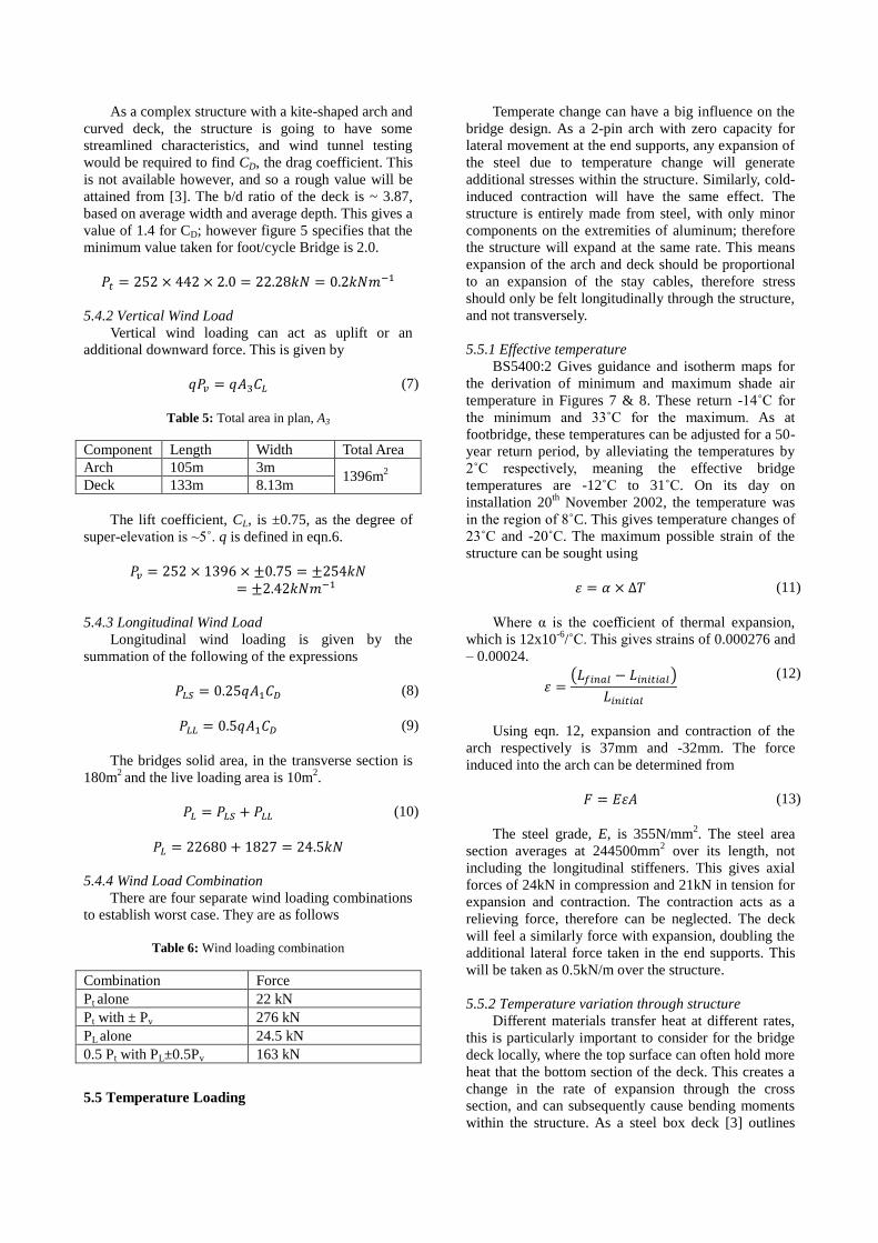
5.4.2 Vertical Wind Load
Vertical wind loading can act as uplift or an
additional downward force. This is given by
(7)
Table 5: Total area in plan, A3
Component Length Width Total Area
Arch 105m 3m 1396m
2
Deck 133m 8.13m
The lift coefficient, CL, is ±0.75, as the degree of
super-elevation is ~5˚. q is defined in eqn.6.
5.4.3 Longitudinal Wind Load
Longitudinal wind loading is given by the
summation of the following of the expressions
(8)
(9)
The bridges solid area, in the transverse section is
180m2 and the live loading area is 10m
2.
(10)
5.4.4 Wind Load Combination
There are four separate wind loading combinations
to establish worst case. They are as follows
Table 6: Wind loading combination
Combination Force
Pt alone 22 kN
Pt with ± Pv 276 kN
PL alone 24.5 kN
0.5 Pt with PL±0.5Pv 163 kN
5.5 Temperature Loading
Temperate change can have a big influence on the
bridge design. As a 2-pin arch with zero capacity for
lateral movement at the end supports, any expansion of
the steel due to temperature change will generate
additional stresses within the structure. Similarly, cold-
induced contraction will have the same effect. The
structure is entirely made from steel, with only minor
components on the extremities of aluminum; therefore
the structure will expand at the same rate. This means
expansion of the arch and deck should be proportional
to an expansion of the stay cables, therefore stress
should only be felt longitudinally through the structure,
and not transversely.
5.5.1 Effective temperature
BS5400:2 Gives guidance and isotherm maps for
the derivation of minimum and maximum shade air
temperature in Figures 7 & 8. These return -14˚C for
the minimum and 33˚C for the maximum. As at
footbridge, these temperatures can be adjusted for a 50-
year return period, by alleviating the temperatures by
2˚C respectively, meaning the effective bridge
temperatures are -12˚C to 31˚C. On its day on
installation 20th
November 2002, the temperature was
in the region of 8˚C. This gives temperature changes of
23˚C and -20˚C. The maximum possible strain of the
structure can be sought using
(11)
Where α is the coefficient of thermal expansion,
which is 12x10-6
/˚C. This gives strains of 0.000276 and
– 0.00024.
(12)
Using eqn. 12, expansion and contraction of the
arch respectively is 37mm and -32mm. The force
induced into the arch can be determined from
(13)
The steel grade, E, is 355N/mm2. The steel area
section averages at 244500mm2 over its length, not
including the longitudinal stiffeners. This gives axial
forces of 24kN in compression and 21kN in tension for
expansion and contraction. The contraction acts as a
relieving force, therefore can be neglected. The deck
will feel a similarly force with expansion, doubling the
additional lateral force taken in the end supports. This
will be taken as 0.5kN/m over the structure.
5.5.2 Temperature variation through structure
Different materials transfer heat at different rates,
this is particularly important to consider for the bridge
deck locally, where the top surface can often hold more
heat that the bottom section of the deck. This creates a
change in the rate of expansion through the cross
section, and can subsequently cause bending moments
within the structure. As a steel box deck [3] outlines

how temperature may vary with distance from the
surface:
5.6 Snow Loading
Clause 5.7.1 of [3] states that snow loading can
generally be neglected for loading combinations 1 – 4,
however as an opening bridge, consideration should be
given. BS6399: Part 3: 1988 Ref.[4], Figure 1 gives
basic snow loading for Newcastle upon Tyne as
0.8kN/m2, this gives total loading of 6.4kN/m along the
deck. Loading over the arch can be neglected due to its
inclination.
5.7 Design Loading
Each loading has its own factors of safety for
ultimate limit state (ULS) and service limit state (SLS),
these have been tabulated below.
Table 5: Loading factors [3]
Load ULS SLS
Dead 1.05 1.0
Super Imposed Dead 1.75 1.2
Live Combination 1 1.5 1.1
Combination 2 & 3 1.25 1.0
Wind 1.1 1.0
Temperature 1.3
1.0
Snow 1.0 0
These values for give the following loadings,
which have been separated between the arch and deck.
Table 6: Final loading over the bridge
Load Location ULS
(kN/m)
SLS
(kN/m)
Dead Arch 19.6 18.7
Deck 63.7 60.7
Super Imposed Dead Deck 5.81 4.0
Liv
e Combination 1 Deck 27 19.8
Combination 2 &
3
Deck 22.5 18
Wind Arch 0.9 0.8
Deck 2.0 1.8
Temperature Arch 0.4 0.3
Deck 0.4 0.3
Snow Deck 6.4 0
These values are very conservative, and due to the
unique nature of the structure a lot of assumption and
estimation was necessary to acquire the values. It
should be noted that computer aided analysis would be
used to simulate these scenarios to gain an accurate
image of the loading on the bridge.
5.7.1 Combination 1
All permanent loads with appropriate live loads
give a total unit loading of 103kN/m of the deck and
19.6kN/m over the arch.
5.7.2 Combination 2
Combination 1, with the addition of wind loading
(there were no erection loads) give a total of
100.4kN/m of the deck and 20.5kN/m over the arch.
5.7.2 Combination 3
Combination 1, with the addition of temperature
loading gives 98.8kN/m over the deck and 20kN/m
over the arch. This puts combination 1 as the worst
case factored loading for ULS, therefore what shall be
used in the structural analysis.
6 Structural Analysis
6.1 Arch analysis
As the bridge tilts, it is important to analyse the
structure in both its positions.
6.1.1 Normal position
Analysis of the arch has the added complication of
the stay cables acting out of plane with the parabola,
generating moments in the arch which get bigger
towards the base. For ULS loading:
Figure 16: Temperature various through deck [3]
Figure 17: Bridge Section

It should be noted that for the arch and deck, the
centroid is approximate 3/5ths of the parabola height.
This was verified by drafting the deck in AutoCAD to
get the mass properties. The hydraulic rams, used to
push against the paddle at the bearing, which in turn
tilts the structure, feels a great deal of compression.
Resolving around the bearing gives R as 70mN.
Breaking this down into reactions at A & B we get
The force component normal to the parabolas
plane, identified in figure x, generates a moment in the
arches normal plane, down to its fixed base.
Over the length of the structure 18 cables are used.
Each cable has a diameter of 45mm, with a tensile
strength of 1350N/mm2. Assuming 5mm strands were
used, each cable consists of 49 strands, giving a total
cross sectional area of 962mm2. This gives a tensile
capacity of 222kN/m over the length of the structure,
which adequately takes the 129kN/m calculates in
Fig.18.
The axial force through the arch and the reaction
forces at the end supports can be found using
(14)
(15)
(16)
For the ultimate limit state design loads, these
return H=4251kN, V=7287kN & Cmax=8437kN. For
the axial force Cmax, the grade 355 steel arch can
tolerate 87MN of compression over its average cross
sectional area of 244965mm2, which is comfortably
within the ULS.
6.1.2 Tilted position
When the structure is tilted, the forces in the
structure change. There isn‟t space in this report to
analysis this in depth, however figure x demonstrates
that because the structure is working more efficiently,
forming a butterfly arch, and live loading is removed,
the stresses through the bridge are less critical than it‟s
its upright position.
The compression reaction force required in the
rams is significantly diminished (R=1069kN) as live
loading is removed and the dead loads are more
balanced. Similarly, there is less tension per unit length
in the cables.
7 Serviceability
Certain components of the structure are designed
to limit necessary maintenance, this includes rubbish
traps that accumulate litter when the bridge tilts, which
falls to the ramp ends under gravity. Maintenance
hatches have also built into the arch and deck so that
internal inspections can be made safely, with no
intrusion to the structure.
Figure 18: Reactions at A & B
Figure 20: Forces in arch
Figure 21: Tilted section
Figure 19: Moment in arch
8 Foundations and Geotechnics
The substructure required for the end supports was
substantial; this is due to both the massive lateral
forces and the fact that the bridge couldn‟t use the
quayside for any support. This led to the end support
structures being cast in-situ within the river channel.
The ground conditions are complex and consist of
non-uniform layers of riverbed gravels on glacial till
which sits on top of coal measures - relatively weak
mudstone and siltstone [1]. This meant the pile caps
had to go down to different depths at each support due
to the slope of these layers. These conditions,
combined with the large horizontal and lateral loading
culminated in a substantial foundation scheme - 14No.
20m deep 1.5m Ø piles were bored for each support.
This is on a comparable scale to the London
Millennium Bridge which uses 16No. 2.1m Ø at each
end to support tensile forces of 30mN in weak London
Clay.
9 Natural Frequency
The structures natural frequency is particularly
important for pedestrian bridges. The frequency should
be above 5Hz [3], if it is lower than this then there is a
large risk of user-induced excitation and vibration,
which could subsequently cause the bridge to be
uncomfortable to users.
Due to the structures complexity, finding the
accurate dynamic behavior of the bridge would only be
possible through wind tunnel testing and computer
modeling. Even finding an approximate value from the
many methods available, including that indicated in
[3], wouldn‟t give an appropriate value even as an
estimate.
The structure was wind tested by the University of
Western Ontario. This involved the simulation of 49m/s
and 33m/s wind speeds over a 1:50 scale model in the
closed and open conditions respectively. It was also
tested at nine angles of tilt and five of wind azimuth.
The testing concluded that the structure didn‟t suffer
from any “aeroelastic instabilities” [5].
10 Durability and Vandalism
The steel bridge is coated in a highly resistant
paint system, with a long-life design, as re-painting the
structure will be a particularly difficult task. The
camber of the deck will encourage run-off of de-icing
salts over the epoxy bound aggregate and prevent
chloride ingress and corrosion.
In terms of structural decay, the stay cables will
lose capacity faster than the deck and arch due to
dynamic relaxation of the strands; however the cable
anchorages are accessible from within the sections
through hatches so can be replaced and re-tensioned
throughout the bridges lifespan, with enough capacity
in the cables for them to be taken out of action one at a
time.
The bridge is conveniently located only 100 yards
away from Newcastle‟s Crown Court, in a rather
affluent and well presented area. As a result of this,
zero tolerance is taken on any graffiti within half a mile
of the quayside, let alone the bridge.
11 Future Changes & Improvements
There are no planned future changes to the
structure; the only thing that may realistically change is
superficial aesthetic detailing (e.g. lighting)
In terms of improvements to the structure, the
author believes a lot less steel could have been used in
the design, with the overdesigning clearly shown in the
analysis. The shape could have been kept using thinner
steel sheets making the bridge lighter and more
efficient and consuming less power when it tilts, yet
still retaining its aesthetic appeal.
12 Acknowledgements
The author would like to thank Dr. Mark Evernden
for his guidance and abetment through the Bridge
Engineering courses and Mr. Steve Duncan of Volker
Stevin for providing photography of the bridge
installation.
References
[1] Johnson, J. Curran, P., 2003. Gateshead
Millennium. Proceedings of the Institution of Civil
Engineers, Civil Engineering, 2003, 156, No.1,
pp.16-24.
[2] Butterworth, K. Carr, D. Kassabian, P., 2003.
Gateshead Millennium Bridge, UK: fabrication,
assembly and erection, Proceedings-Institution of
Civil Engineers Bridge Engineering, Vol. 156,
No.1, pp.11-20.
[3] BS5400-2: 2006. 2006. Steel, concrete and
composite bridges – Part 2: Specification for
loads. British Standards Institute.
[4] BS6399- 3: 1988. 1988. Loading for buildings.
Code of practice for imposed roof loads. British
Standards Institute.
[5] Davenport, A. 1998. The Baltic Millennium
Footbridge, Gateshead, UK. Wind Engineering
Study. Available from
http://www.blwtl.uwo.ca/User/Doc/Baltic%20Mill
ennium%20Footbridge,%20Gateshead,%20UK.pd
f [Accessed 21st March 2011].
[6] Britton, I. 2004. Various photos of the Gateshead
Millennium Bridge. At:
http://www.freefoto.com/browse/1044-00-
0?ffid=1044-00-0 [Accessed 21st March
2011].Individual References? [7] Duncan, S., ([email protected]),
29 March 2011. Gateshead Millennium Bridge
Photos. Email to Butler, T. ([email protected])