A CONTROL TECHNIQUE FOR SHIELDED METAL ARC WELDING …
9
A CONTROL TECHNIQUE FOR SHIELDED METAL ARC WELDING IMPROVEMENT Jongkol Srithorn 1,* , Phinit Srithorn 2 , and Mongkol Danbumrungtrakul 2 Received: October 02, 2017; Revised: October 20, 2017; Accepted: October 25, 2017 Abstract Shielded metal arc welding remains popular for cost-effective manufacturing of joining materials, and seems to be quite common in a large number of engineering applications. However, in order to achieve reliable quality, the lack of skilful welders appears to be a crucial situation which is now being discussed. Therefore, this paper presents a solution to make the most of commercial arc welding machines, with a system capable of improving both quality and quantity. A control technique with the definite ability to increase the welding quality is proposed by automatically varying the arc length in a repeating pattern during the melting mechanism. For this idea, the hysteresis concept was applied as a key controller to preform regulation employing an indirect control through arc voltage feedback, which yielded the arc distance being varied continuously in a desired band; this is similar to what most skilful welders usually do. A prototype system is described with details that provide researchers with some convenient shortcuts for repeating the technique. Validation using an experimental rig was conducted, and the results illustrate that the proposed technique was able to give a satisfactory arc variation to the weld process that is associated with the melting mechanism. Different results from case studies are also described in this paper indicating that, with the system, the quality of the resulting welds was improved. Therefore, it can be envisaged that the technique will be a potential benefit for usage in electric arc welding. Keywords: Arc length, arc melting control, weld trace improvement, hysteresis concept 1 School of Industrial Engineering, Suranaree University of Technology, Nakhon Ratchasima, 30000, Thailand. E-mail: [email protected] 2 Department of Electrical Engineering, Rajamangala University of Technology Isan, Nakhon Ratchasima, 30000, Thailand. * Corresponding author Suranaree J. Sci. Technol. 24(3):281-289
Transcript of A CONTROL TECHNIQUE FOR SHIELDED METAL ARC WELDING …

281 Suranaree J. Sci. Technol. Vol. 24 No. 3; July – September 2017
A CONTROL TECHNIQUE FOR SHIELDED METAL ARC WELDING IMPROVEMENT Jongkol Srithorn1,*, Phinit Srithorn2, and Mongkol Danbumrungtrakul2
Received: October 02, 2017; Revised: October 20, 2017; Accepted: October 25, 2017
Abstract
Shielded metal arc welding remains popular for cost-effective manufacturing of joining materials, and seems to be quite common in a large number of engineering applications. However, in order to achieve reliable quality, the lack of skilful welders appears to be a crucial situation which is now being discussed. Therefore, this paper presents a solution to make the most of commercial arc welding machines, with a system capable of improving both quality and quantity. A control technique with the definite ability to increase the welding quality is proposed by automatically varying the arc length in a repeating pattern during the melting mechanism. For this idea, the hysteresis concept was applied as a key controller to preform regulation employing an indirect control through arc voltage feedback, which yielded the arc distance being varied continuously in a desired band; this is similar to what most skilful welders usually do. A prototype system is described with details that provide researchers with some convenient shortcuts for repeating the technique. Validation using an experimental rig was conducted, and the results illustrate that the proposed technique was able to give a satisfactory arc variation to the weld process that is associated with the melting mechanism. Different results from case studies are also described in this paper indicating that, with the system, the quality of the resulting welds was improved. Therefore, it can be envisaged that the technique will be a potential benefit for usage in electric arc welding. Keywords: Arc length, arc melting control, weld trace improvement, hysteresis concept
1 School of Industrial Engineering, Suranaree University of Technology, Nakhon Ratchasima, 30000, Thailand. E-mail: [email protected] 2 Department of Electrical Engineering, Rajamangala University of Technology Isan, Nakhon Ratchasima, 30000, Thailand. * Corresponding author
Suranaree J. Sci. Technol. 24(3):281-289

282 A Control Technique for Shielded Metal arc Welding Improvement
Introduction
The application of arc welding is an important part of several types of engineering work. Its performance will be varied in relation to the melting mechanism applied for each individual process and the welding conditions (Davies, 1993; Zhang and Walcott, 2006). Normally, the resulting welds reflect both the physical strength and appearance aspects, especially for the final results that usually are seen as representatives of the overall work. Mostly, the arc welding process is conducted manually, and its quality varies depending on the welders. The process also seems to be hazardous when conducted with improper precautions (Freschi et al., 2017). As mentioned, the manual welding process relies solely on humans, and therefore its productivity is inevitably low (Liu et al., 2017). Also, the welding’s reliability is hopefully expected to meet requirements both in quality and quantity (Cary, 2002). For manufacturing, fully automatic welding machines are required to achieve the finest results; otherwise, skillful welders should be employed for a variety of tasks. For most owners of small and medium enterprises (SMEs) who have their limitations well in mind, purchasing any expensive machines will need to be considered as a capital investment. Additionally, employing welders is the only solution to get the best out of using any commercially available welding machines - shielded metal arc welding (SMAW) tools. However, some consider that a crucial problem is the lack of skillful welders which seems to be the issue limiting the capability of the SMEs and, thus, their economic driving force.
It is certain that, for welders to be qualified with the proper experience, the investment will not only be in cost but also in time. Providing any systems that are aimed at assisting unskilled welders can be one of the solutions for the near future, preferably for routine manufacturing in which the welding is processed repeatedly. It is quite certain that more complicated systems will be included to provide improvements for the arc welding process (Bonaccorso et al., 2011; Navarro-
Crespin et al., 2013; Paul, 2016; Liu et al., 2017), which will eventually require more investment. This paper proposes a system designed with a hysteresis control concept, aiming to make it simple and inexpensive. The key idea is to apply a technique that is initially obtained from empirical studies of how skillful welders normally operate, combined with the hysteresis control concept in order to keep the arc melting phenomenon remain in a continuous and stable progression. With the use of a voltage signal (Rossi et al., 2011), variation of the arc length was conducted in order to analyse it for benefit to shielded metal arc welding. The low-cost system will offer the desired performance as a solution to improve both the quantity and quality. The test results also showed that this technique is quite flexible and suitable for many different applications.
In this paper, the proposed system is described with experimental tests proving that it can provide sufficient ability to assist the arc welding process that employs an SMAW machine. Different hysteresis thresholds were set up to study the performance, which can be seen as an example of system tuning. The resulting welds can be improved accurately to meet requirements. With a microcontroller inside, the system then provides flexibility for re-programming to make more improvements.
The Proposed System
Following the arc voltage and its corresponding length relationship mentioned in Rossi et al. (2011), this system employs an indirect technique to adjust the arc length using an inexpensive structure, as shown in Figure 1, providing controllability to the arc welding. The idea behind this system is to keep the arc length varied continuously and repeated within a band during the melting process. To support the control idea, it can be seen in the figure that a two-axis structure with both vertical and horizontal movement is used for providing sufficient controllability to the system. Therefore, the distance between the electrode tip and the workpiece will be adjusted instantly, depending on the evaluation of the

283 Suranaree J. Sci. Technol. Vol. 24 No. 3; July – September 2017
arc voltage conditions. Both of them are placed on each of the axes, with sliders driven by electric motors M1 and M2, as shown in Figure 1. The arc length is adjusted vertically through the control of the motor drives, while the workpiece is being conveyed to the arc point. Change of arc lengths is therefore controlled and limited to prevent a discontinuous melting process.
According to this structure, during the melting process, the control actions to drive the welding electrode up and down are interpreted using the arc voltage signal at the welding
machine terminals and are monitored and further evaluated for the right control actions. The system will react to the welding dynamics in order to achieve the entire arc length variation pattern repeatedly, providing the desired actively responsive system. With the application of the hysteresis concept, the controller will allow some arc intervals for completing the melting mechanism, respecting its thresholds. This technique also provides repeatability for continuous patterns to be adjusted for the modulation of both the width and depth of the resulting welds. Whenever the position of the electrode tip varies, the voltage across the arc phenomenon will also be varied in respect to the arc-gap distance. Evaluation to comply with its corresponding variation will be executed for the right control decisions.As a result, if the electrode tip approaches too close to the workpiece during the melting arc, it will be driven upward until it reaches the
upper threshold; and then vice versa downward until it reaches the lower threshold. Due to the accurate movement of the motors, this proposed system will achieve continuous operation until the end of the welding electrode, and can be programmed to work with a range of intervals for any further improvement that is required. Flexibility is also included in the process, as tuning is allowed at the beginning in order to match the structure’s movement with the available welding machines.
Control Design
It is well known that the welding mechanism always comes with an uncertain nature; typical dynamics may vary the unpredictability (Zhang and Walcott, 2006; Rossi et al., 2011). So, to have a precise modulation in order to preform the welding regulation for accurate width and depth of the welds seems to be a complicated process consisting of many components. The control proposed here is a kind of hysteresis concept, with the key operating technique obtained from empirical studies and employing a simple technique and structure, as described in the previous section. To achieve the continuous arc melting for the entire range of times, the process needs to perform in patterns set up by a threshold band. The welding electrode is then controlled by moving up and down along the vertical axis. Therefore, both the upper and lower thresholds of the hysteresis band are important (Killball et al., 2006; Leung and Chung, 2005; Khazraei et al., 2013) ; in this case, the thresholds define not only the boundary for the electrode tip movement but also the time for further accumulation of the melting metal and the induced heat at any instant of the weld traces. They play a role for this kind of welding improvement that will result in a controlled arc length, and the weld’s quality is improved consequently.
The control applied for this system is set out as a diagram and is shown in Figure 2; the control target is to move the welding electrode upward and downward through driving the
Figure 1. The overall system structure
284 A Control Technique for Shielded Metal arc Welding Improvement
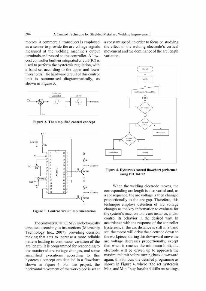
motors. A commercial transducer is employed as a sensor to provide the arc voltage signals measured at the welding machine’s output terminals and passed to the controller. A low-cost controller built-in integrated circuit (IC) is used to perform the hysteresis regulation, with a band set according to the upper and lower thresholds. The hardware circuit of this control unit is summarised diagrammatically, as shown in Figure 3.
The controller IC #PIC16F72 is electronically circuited according to instructions (Microchip Technology Inc., 2007), providing decision making that acts to increase a more reliable pattern leading to continuous variation of the arc length. It is programmed for responding to the monitored arc voltage changes, and some simplified executions according to this hysteresis concept are detailed in a flowchart shown in Figure 4. For this project, the horizontal movement of the workpiece is set at
a constant speed, in order to focus on studying the effect of the welding electrode’s vertical movement and the dominance of the arc length variation.
When the welding electrode moves, the corresponding arc length is also varied and, as a consequence, the arc voltage is then changed proportionally to the arc gap. Therefore, this technique employs detection of arc voltage changes as the key information to evaluate for the system’s reaction to the arc instance, and to control its behavior in the desired way. In accordance with the response of the controller hysteresis, if the arc distance is still in a band set, the motor will drive the electrode down to the workpiece; during this downward move the arc voltage decreases proportionally, except that when it reaches the minimum limit, the electrode will be driven up to approach the maximum limit before turning back downward again; this follows the detailed programme as shown in Figure 4, where “the set hysteresis Max. and Min.” step has the 4 different settings
Figure 3. Control circuit implementation
Figure 4. Hysteresis control flowchart performed using PIC16F72
Figure 2. The simplified control concept

285 Suranaree J. Sci. Technol. Vol. 24 No. 3; July – September 2017
for the experiment:- 1.5 - 2.8 V, 1.5 - 2.5 V, 1.5 - 2.2 V, and 1.5 - 1.9 V. With this process, the melting arc will be modulated continuously within the desired lengths, so that different hysteresis bands are expected to give different results for the experiment, as explained in section 4.
Experiment
The arc length modulation process was carried out while conducting the shielded metal arc welding tests, aiming to demonstrate the improvement in the weld’s quality and its satisfactory appearance. It can be predicted that the controlled arc lengths would result in different arc voltage magnitudes that can be adjusted through the movement of the electrode tip, as previously mentioned. To verify that simple hysteresis bands can have more of an effect on the welding, a commercial arc welding machine (Welder model BX-200B, Taizhou Retop Mechanical & Electrical Co. Ltd., Taizhou, Zhejiang, China) with its current rating at 160 A was applied to do the beads on plate welding at a constant welding speed; 3 mm thick low carbon steel metal was used as the workpiece. The electrode diameter used in this experiment was 3.2 mm. Prior to carrying out the experiments, several pre-tests were conducted manually in order to determine the threshold levels for the hysteresis control settings, and to confirm the relationship between the arc voltages and associated gap distances.
From those pre-tests, prior to the initial spark of the arcs, the average voltage magnitude at the machine’s terminals was about 4 V (transduced and conditioned electronically with an attenuation ratio of 11.92). When the arc sparked, its relevant voltage reduced linearly relating to its instant arc length, as expected. For this experiment, in order to complete the studies, relative thresholds of the hysteresis bands must be set with an upper and a lower limit. The upper thresholds were varied up to the maximum level, which was practically derived from its probability of the initial arcs that was around
2.8 V. For the lower threshold, it was fixed at a level that demanded the maintenance of the arc column during the melting phenomenon (Rossi et al., 2011). Several pre-tests using the aforementioned rig showed the minimum threshold of around 1.5 V (at lower than this level, the arc disappeared). Experiments were then carried out at 4 different upper hysteresis settings, as detailed in the following section.
Arc Voltage Controlled from 1.5 V to 2.8 V
With this upper threshold, the electrode movement was controlled relating to the corresponding band 1.5 V-2.8 V, and the arc length was then varied continuously up to a distance related to this band, and repeated as a pattern. The arc voltage was measured (transduced and recorded), as displayed in Figure 5, with the resulting weld shown in Figure 6. Highly intermittent signals seen in Figure 5 mean that the arc voltage was being fluctuated in the same manner. This also indicates that, with this setting, during the melting phenomenon the control system allowed the electrode to jump away to positions too far from the workpiece, especially at the beginning of the arc phenomenon (highlighted with the number 1 in Figure 5). In relation to the corresponding weld shown in Figure 6, the non-continual weld trace appeared suddenly after starting the test.
Figure 5. Arc-voltage controlled within 1.5 V – 2.8 V

286 A Control Technique for Shielded Metal arc Welding Improvement
According to this, the results imply that due to this band the driving structure was not controlled properly, and often caused an improper arc distance when dealing with uncertain sparks; many times the control provided actions that resulted in the electrode jumping out of the reference levels, even in the period after starting. As a consequence, the arc was extinguished instantly, and the melting mechanism was eventually halted. With its response, the controller itself was able to detect
this failed action and tried to narrow the gap intending to re-spark the arc. Then, the electrode tip was driven downward quickly targeting the workpiece and causing a sudden drop of the arc voltage magnitude.
Later, it detected that the gap was too close to maintain the arc voltage; the drive acted to widen the gap again to a point beyond its upper limit. While this non-continuous arc repeated itself as the pulsation signals show in Figure 5, subsequently induced heat accumulated at the workpiece’s metal until it warmed up to reach the melting mechanism level and could spark with ease (Rossi et al., 2011). Eventually, a kind of continual arc was seen in Figure 6, highlighted with the number 2. An irregular weld bead was found and the weld bead appeared to tend to have spatter along the weld due to the arc length being too long and the arc being unstable during this experiment.
Arc Voltage Controlled from 1.5 V to 2.5 V
It should be pointed out that the control setting for the test described in the previous section resulted in an improper gap distance for the metal melting mechanism, and the process was unable to keep the arc remaining in a state of continuity. Then, as a rule of thumb, a narrower 1.5V – 2.5 V band was set for the test in order to support this analysis and to have more continuous welding. This second setting did not result in welds that were much different compared with the previous one, and the arc voltage signal and the resulting welds are shown in Figures 7 and 8, respectively. Less oscillating pulses of the arc voltage associated with the relevant electrode movement can still be seen at the start (numbered 1 in Figure 7), and also for later in the process highlighted with the number 2 in Figure 7.
Compared to the voltage signal shown in Figure 5, the highly pulsating signal had been reduced. However, pulsation effects during the arc melting were still in evidence at some points on the weld trace shown in Figure 8 - even in the middle of the second period. An
Figure 6. The weld result when arc-voltage controlled within 1.5 V – 2.8 V
Figure 7. Arc-voltage controlled within 1.5 V – 2.5 V
Figure 8. The weld result when arc-voltage controlled within 1.5 V – 2.5 V
287 Suranaree J. Sci. Technol. Vol. 24 No. 3; July – September 2017
inconsistent weld bead was found due to the arc pulsation. It was understandable that the modulated hysteresis band was still not matched with this rig setup. In terms of signal evaluations, looking forward to reducing the arc pulsation and its electrode jumping, the control band should have been narrower.
Arc Voltage Controlled from 1.5 V to 2.2 V
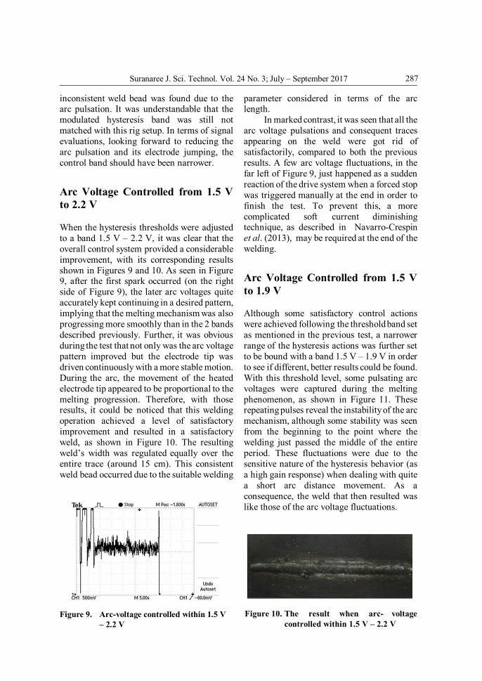
When the hysteresis thresholds were adjusted to a band 1.5 V – 2.2 V, it was clear that the overall control system provided a considerable improvement, with its corresponding results shown in Figures 9 and 10. As seen in Figure 9, after the first spark occurred (on the right side of Figure 9), the later arc voltages quite accurately kept continuing in a desired pattern, implying that the melting mechanism was also progressing more smoothly than in the 2 bands described previously. Further, it was obvious during the test that not only was the arc voltage pattern improved but the electrode tip was driven continuously with a more stable motion. During the arc, the movement of the heated electrode tip appeared to be proportional to the melting progression. Therefore, with those results, it could be noticed that this welding operation achieved a level of satisfactory improvement and resulted in a satisfactory weld, as shown in Figure 10. The resulting weld’s width was regulated equally over the entire trace (around 15 cm). This consistent weld bead occurred due to the suitable welding
parameter considered in terms of the arc length.
In marked contrast, it was seen that all the arc voltage pulsations and consequent traces appearing on the weld were got rid of satisfactorily, compared to both the previous results. A few arc voltage fluctuations, in the far left of Figure 9, just happened as a sudden reaction of the drive system when a forced stop was triggered manually at the end in order to finish the test. To prevent this, a more complicated soft current diminishing technique, as described in Navarro-Crespin et al. (2013), may be required at the end of the welding.
Arc Voltage Controlled from 1.5 V to 1.9 V
Although some satisfactory control actions were achieved following the threshold band set as mentioned in the previous test, a narrower range of the hysteresis actions was further set to be bound with a band 1.5 V – 1.9 V in order to see if different, better results could be found. With this threshold level, some pulsating arc voltages were captured during the melting phenomenon, as shown in Figure 11. These repeating pulses reveal the instability of the arc mechanism, although some stability was seen from the beginning to the point where the welding just passed the middle of the entire period. These fluctuations were due to the sensitive nature of the hysteresis behavior (as a high gain response) when dealing with quite a short arc distance movement. As a consequence, the weld that then resulted was like those of the arc voltage fluctuations.
Figure 9. Arc-voltage controlled within 1.5 V – 2.2 V
Figure 10. The result when arc- voltage controlled within 1.5 V – 2.2 V

288 A Control Technique for Shielded Metal arc Welding Improvement
Differences found from this setting were not only the weld’s width but also the undercut. The weld shown in Figure 12 was wider than the other 3 previously mentioned. Moreover, it was seen clearly that the trace appeared not to be in the expected straight line. Its depth was too much into the metal, which we could notice from the other side of the workpiece. This depth level could even damage the metal (depending on type of electrode), and reflected that it was unacceptable. This was due to too much heat induced at the arc when conducted into too narrow a gap at the metal melting process.
Conclusions
According to the experimental results, a technique obtained from empirical studies and then combined with the hysteresis concept can provide stability to the shielded metal arc welding in order to improve its quality and quantity, in manufacturing terms. The
proposed system, simple and inexpensive, can continuously and automatically assist adjustment of the arc length during the melting. Fine tuning can be achieved using this inexpensive system through the programming, in order to match the structure with different welding machines. The environment has more of an effect on the initial arc; hot and cold electrodes result in a different first spark voltage, which may be hard to predict for a suitable gap length, and external heat may be needed to provide a smooth start for the welding.
From the experimental tests, the hysteresis thresholds play a major role that affects the arc welding - both the weld trace and its corresponding quality. When the arc length was varied continuously up to a distance where the gap became too wide, the welding became an unstable melting process and the conclusion was that it caused unacceptable results. In contrast, if the gap was too narrow, the arc progression allowed more heat to be induced and accumulated at the melting metals, and caused too deep a weld to be embedded in the workpiece that could possibly damage the metal. However, with this technique, the gap length can be adjusted suitably through the reliable control process; it was possible to tune it for a better one at least and the suitable weld bead can be obtained using this technique with various experiments in future work.
Acknowledgments
The authors would like to extend deep gratitude to Suranaree University of Technology and Rajamangala University of Technology Isan for the analytical tool.
References
Bonaccorso, F., Cantelli, L., and Muscato, G. (2011). An arc welding robot control for a shaped metal deposition plant: Modular software interface and sensors. IEEE T. Ind. Electron., 63(6):3717-3724.
Cary, H.B. (2002). Modern Welding Technology. 5th ed. Prentice Hall, Upper Saddle River, NJ, USA, 801p.
Figure 11. Arc-voltage controlled within 1.5 V – 1.9 V
Figure 12. The weld result when arc-voltage controlled within 1.5 V – 1.9 V

289 Suranaree J. Sci. Technol. Vol. 24 No. 3; July – September 2017
Davies, A.C. (1993). The Science and Practice of Welding. vol 2. 10th ed. Cambridge University Press, Cambridge, UK, 521p.
Freschi, F., Giaccone, L., and Mitolo, M. (2017). Arc welding process: An electrical safety analysis. IEEE T. Ind. Appl., 53(2):819-825.
Khazraei, M., Sepahvand, H., Ferdowsi, M., and Corzine, K.A. (2013). Hysteresis-based control of a single-phase multilevel flying capacitor active rectifier. IEEE T. Power Electr., 28(1):154-164.
Killball, J.W., Krein, P.T., and Chen, Y. (2006). Hysteresis and delta modulation control of converters using sensorless current mode. IEEE T. Power Electr., 21(4):1154-1158.
Leung, K.K. and Chung, H.S. (2005). Dynamic hysteresis band control of the buck converter with fast transient response. IEEE T. Circuits-II, 52(7):398-402.
Liu, J., Fan, Z., Olsen, S.I., Christensen, K.H., and Kristensen, J.K. (2017). Boosting active contours for weld pool visual tracking in automatic arc welding. IEEE T. Autom. Sci. Eng., 14(2):1096-1108.
Microchip Technology Inc. (2007). PIC16F72 Data Sheet: 8-Bit CMOS Flash Microcontroller. Microchip Technology Inc., Chandler, AZ, USA, 134p.
Navarro-Crespin, A., Lopez, V.M., Casanueva, R., and Azcondo, F.J. (2013). Digital control for an arc welding machine based on resonant converters and synchronous rectification. IEEE T. Ind. Inform., 9(2):839-847.
Paul, A.K. (2016). Robust product design using SOSM for control of shielded metal arc-welding (SMAW) process. IEEE T. Ind. Electron., 63(6):3717-3724.
Rossi, M.L., Ponomarev, V., and Scotti, A. (2011). Heat exchange and voltage drop in welding arc column. IEEE T. Plasma Sci., 58(8):2446-2454.
Zhang, J. and Walcott, B.L. (2006). Adaptive interval model control of arc welding process. IEEE T. Contr. Syst. T., 14(6):1127-1133.