A CONCEPTUAL MODEL FOR WEB-BASED …plaza.ufl.edu/nnleung/mspapers/LeungNN.pdf · a conceptual...
198
A CONCEPTUAL MODEL FOR WEB-BASED CONSTRUCTION PROJECT MANAGEMENT LEUNG NGA NA (B. Arch., Tongji University, China) A THESIS SUBMITTED FOR THE DEGREE OF MASTER OF SCIENCE DEPARTMENT OF BUILDING SCHOOL OF DESIGN AND ENVIRONMENT NATIONAL UNIVERSITY OF SINGAPORE 2002
Transcript of A CONCEPTUAL MODEL FOR WEB-BASED …plaza.ufl.edu/nnleung/mspapers/LeungNN.pdf · a conceptual...

A CONCEPTUAL MODEL FOR
WEB-BASED CONSTRUCTION PROJECT MANAGEMENT
LEUNG NGA NA
(B. Arch., Tongji University, China)
A THESIS SUBMITTED
FOR THE DEGREE OF MASTER OF SCIENCE
DEPARTMENT OF BUILDING
SCHOOL OF DESIGN AND ENVIRONMENT
NATIONAL UNIVERSITY OF SINGAPORE
2002

ACKNOWLEDGEMENTS
I would like to express my deepest gratitude towards Dr. Chan Swee Lean, my
supervisor, for her excellent advice, guidance, patience, and time, without which this
work would not have been possible. It was a great pleasure and precious experience
working with her.
My sincere appreciation is given to Dr. Wang Shouqing, Dr. George Ofori,
and Dr. Goh Bee Hua, for their excellent guidance, valuable comments in the research
and the academic life.
Also I would like to thank Yang Yiqing, Gao Xia, Liu Yinsheng, and Mao
Zhi, who have devoted tremendous helps to my research adventure. My earnest
gratitude goes to my research fellows – Li Yan, Lin Chao, Peng Zhen, Shi Yuquan,
Song Yan, Wang Yong, and Yang Haishan, whose inspiration and friendship are the
spiritual source of my expedition.
Special thanks are given to my dear family, relatives, and friends for their
endless love and concerns; and Zhan Lezhou for his understanding and
encouragement.
ii

TABLE OF CONTENTS
ACKNOWLEDGEMENTS TABLE OF CONTENTS LIST OF FIGURES LIST OF TABLES LIST OF ACRONYMS SUMMARY
ii iii vii ix x
xi CHAPTER 1 INTRODUCTION 1.1 RESEARCH BACKGROUND 1.2 RESEARCH PROBLEMS AND RATIONAL 1.3 RESEARCH OBJECTIVES 1.4 RESEARCH SCOPE 1.5 RESEARCH METHODOLOGY 1.6 ORGANIZATION OF THE DISSERTATION
1124457
CHAPTER 2 LITERATURE REVIEW 2.1 INTRODUCTION 2.2 IT-RELATED PROBLEMS IN THE AEC INDUSTRY 2.2.1 Fragmentation 2.2.2 Data Incompatibility 2.3 INFORMATION INTEGRATION 2.3.1 Managerial Integration 2.3.1.1 Process Redesign 2.3.1.2 Concurrent Engineering 2.3.2 Technical Integration 2.3.2.1 Back-End Integration 2.3.2.2 Front-End Integration 2.4 INTERNETWORKING AND APPLICATION 2.4.1 Internetworking Technology 2.4.1 Internetworking Applications 2.5 STANDARDIZATION 2.5.1 Standard For The Exchange Of Product Model Data 2.5.2 Industry Foundation Classes 2.6 CONCEPTUAL MODELING METHODOLOGIES 2.6.1 The STEP Methodology 2.6.2 The UML Methodology 2.7 EXTENSIBLE MARKUP LANGUAGE 2.7.1 BcXML 2.7.2 AecXML 2.7.3 IfcXML 2.8 SUMMARY
1010101012131314151516161818192222222324262627282829
CHAPTER 3 FUNCTIONAL REQUIREMENTS OF ASPS 3.1 INTRODUCTION 3.2 HISTORY OF ASP DEVELOPMENT 3.3 AS-IS FEATURES 3.4 TO-BE FEATURES
3030303134
iii

3.4.1 Time And Cost Considerations 3.4.2 Integration 3.4.3 Intelligent Search For Information 3.4.4 Knowledge Base 3.4.5 Customizability To Persons 3.4.6 Customizability To Projects 3.4.7 Scalability 3.4.8 Others 3.5 ASPS IN SINGAPORE 3.6 ASP BENEFITS 3.6.1 Improved Communication 3.6.2 Reduction On Project Life Cycle Time 3.6.3 Reduction On Cost 3.6.4 Accountability And Records 3.6.5 Gaining Competitive Advantages 3.7 OBSTACLES TO ADOPTION OF ASP 3.7.1 Economic Considerations 3.7.2 Organizational Changes 3.7.3 Lack Of ASP Standards 3.7.4 Other Obstacles 3.8 SUMMARY
353536363637373737383940414142434344454646
CHAPTER 4 EMPIRICAL STUDY OF USER REQUIREMENTS 4.1 INTRODUCTION 4.2 SURVEY METHODOLOGY 4.2.1 Sample 4.2.2 Web-based Survey 4.2.3 Confidentiality 4.2.4 Survey Organization and Design 4.2.5 Technical Details 4.2.6 Survey Distribution 4.2.7 Potential Sources Of Biasness 4.3 DATA ANALYSIS 4.4 OVERALL FINDINGS AND ANALYSIS 4.4.1 Part 1 Respondent Profiles 4.4.2 Part 2 General Use Of IT And Networking 4.4.3 Part 3 Uses Of ASP 4.4.3.1 Acceptance Of ASP 4.4.3.2 Awareness Of ASP 4.4.3.3 Expected Impacts On Time 4.4.3.4 Evaluation Of As-Is Features 4.4.3.5 Evaluation Of To-Be Features 4.4.3.6 Comments On ASP 4.5 SUMMARY
47474747484949525252545555565959616365666666
CHAPTER 5 CONCEPTUAL MODEL DEVELOPMENT 5.1 INTRODUCTION 5.2 THE UML MODELING METHOD 5.2.1 The UML Modeling Approaches 5.2.2 Use Case Documents
6969697073
iv

5.3 MAJOR ACTORS 5.4 THE MAIN USE CASE 5.4.1 Setup Project Service 5.4.2 Setup Project Website 5.4.3 Setup User 5.4.4 Log In 5.4.5 Package Manage Document 5.4.6 Package Manage Workflow 5.4.7 Package Team Communication 5.4.8 Package My Project Place 5.4.9 Administrate Project 5.5 SUMMARY
747576767778788184858586
CHAPTER 6 PROTOTYPING OF REQUEST FOR INFORMATION 6.1 INTRODUCTION 6.2 THE REQUEST FOR INFORMATION SCENARIO 6.3 USE CASES INVOLVED 6.4 EXTENSIBLE MARKUP LANGUAGE 6.4.1 XML In The Scenario 6.4.1.1 Schemas For Response To Request For Information (ReRFI) 6.4.1.2 XML File For The Response To Request For Information 6.4.2 XML Presentation 6.4.3 Schema Mapping Between IfcXML And Document XML 6.4.4 The Integrated Webpages 6.4.5 Applications 6.5 SUMMARY
878787
102103104105109109111113115116
CHAPTER 7 CONCLUSIONS AND RECOMMENDATIONS 7.1 INTRODUCTION 7.2 GENERAL CONCLUSIONS 7.3 IMPLICATIONS 7.4 LIMITATIONS AND RECOMMENDATIONS
117117117119121
REFERENCES 123 APPENDIX I ASP AS-IS FEATURES I.1 GENERAL SYSTEM I.2 DOCUMENT MANAGEMENT I.3 WORKFLOW MANAGEMENT I.4 ADMINISTRATION I.5 USER CENTRIC WORKPLACE I.6 TEAM COMMUNICATION I.7 ASP SERVER PERFORMANCE
130130130132134135136137
APPENDIX II SURVEY QUESTIONNAIRE 139 APPENDIX III THE CONCEPTUAL MODEL III.1 MAJOR ACTORS III.2 THE MAIN USE CASE III.2.1 Setup Project Service
152152153154
v

III.2.2 Setup Project Website III.2.3 Setup User III.2.4 Log In III.3 PACKAGE MY PROJECT PLACE III.3.1 View What’s New III.3.2 Manage My Task III.3.3 Manage My Profile III.3.3.1 Request For Role Change III.3.4 Manage Subscription III.4 PACKAGE MANAGE DOCUMENT III.4.1 Upload File III.4.2 Search File III.4.3 Search Topic III.5 PACKAGE MANAGE WORKFLOW III.5.1 Manage Change III.5.1.1 Manage RFI III.5.1.2 Manage Variation Order III.5.2 Manage My Work Package III.6 PACKAGE TEAM COMMUNICATION III.6.1 View BBS III.7 PACKAGE ADMINISTRATE PROJECT III.7.1 Setup User
154155157158158159160161163164165166167169169170172173174175176176
APPENDIX IV XML DOCUMENTS FOR RERFI IV.1 HTML FILE OF RERFI IV.2 XML SCHEMA OF RERFI IV.3 SOURCE CODES OF RERFI SCHEMA IV.4 XML FILE OF RERFI IV.5 SOURCE CODES OF RERFI XML
177177179181184185
vi

LIST OF FIGURES
Figure 1.1 Document-Based System: Fragmented Information. Figure 1.2 DMI System: Multiple Views Of The Same Data. Figure 1. 3 Flow Chart Denoting The Relationships Among The Chapters And
Appendices.
238
Figure 2.1 Fragmentation During Project Phases And Among Participants. Figure 2.2 Hierarchy Of Information Integration. Figure 2.3 Process Redesign And Return On Investment. Figure2.4 Configuration Of A Document Management. Figure 2.5 Components Of The CORENET Project. Figure 2.6 IFC2x Architecture.
111314172124
Figure 3.1 Illustration Of Projected Construction Industry Software Evolution.
31
Figure 4.1 Screen Shot of The Survey. Figure 4.2 Flowchart Of The Web-Based Survey. Figure 4.3 Type Of Company. Figure 4.4 Job Duty. Figure 4.5 Years Of Working Experience. Figure 4.6 Purpose Of Company Homepage. Figure 4.7 Access Of Internet. Figure 4.8 Mean Proportions Of Staff Using IT. Figure 4.9 Mean Proportions For Document Exchanges. Figure 4.10 Mean Scales Of IT Effects. Figure 4.11 Major Benefits Of Using ASP. Figure 4.12 Major Concerns Of Using ASP. Figure 4.13 Overall Awareness Of ASPs. Figure 4.14 Overall Awareness Of Local Services. Figure 4.15 Mean Scales Of ASP Effects On Time. Figure 4.16 Evaluation Of ASP As-Is Features In Terms Of Mean Scales. Figure 4.17 Evaluation Of ASP To-Be Features In Terms Of Mean Scales.
4951565656575858595960616262646566
Figure 5.1 Actor And Use Cases. Figure 5.2 Activity Diagram. Figure 5.3 Packages. Figure 5.4 User Inheritances. Figure 5.5 Main Use Case. Figure 5.6 Setup Project Website. Figure 5.7 Manage Document Inheritance. Figure 5.8 Manage Document. Figure 5.9 Upload File. Figure 5.10 Search File. Figure 5.11 Search Topic. Figure 5.12 Package Management Workflow. Figure 5.13 Manage Change. Figure 5.14 Workflow Of RFI.
7172727576777878797981828283
vii
Figure 5.15 Team Communication. Figure 5.16 My Project Place. Figure 5.17 Administrate Project.
848586
Figure 6.1 Original Detail Drawings Of The Parapet. Figure 6.3 Collaboration Diagram Of The Paper-Based Process. Figure 6.4 Collaboration Diagram Of The DMI Process. Figure 6.4 Proposed Detail Drawings Of The Parapet. Figure 6.5 RFI Created By YS Liu. Figure 6.6 Part Of RFI Responded By K Foo. Figure 6.7 Part Of RFI Responded By M Ang. Figure 6.8 Summary Of RFI. Figure 6.9 Document Data Exchange. Figure 6.10 Document Data Exchange Between ReRFI And QFC. Figure 6.11 Top Level Elements In ReRFI Schema. Figure 6.12 RFI Complex Type In ReRFI Schema. Figure 6.13 Response Complex Type In ReRFI Schema. Figure 6.14 LinkFile Complex Type In ReRFI Schema. Figure 6.15 ActorSelect Complex Type In ReRFI Schema. Figure 6.16 XML File Of ReRFI. Figure 6.17 Information Exchange Architecture Of The DMI System.
88898993979999
100105105106107108108108110115
viii

LIST OF TABLES
Table 5.1 Use Case Document Template. 73 Table 6.1 Person, Role And Company . Table 6.2 Comparison Of Paper-Based And DMI Processes. Table 6.3 Request For Information Form. Table 6.4 Part Of The Original Quotation. Table 6.5 Quotation For Change Form. Table 6.6 Use Cases Involved In The Dmi Rfi Process. Table 6.7 Schema Mapping Between Ifcxml And Rerfi Xml.
8890949595
103112
ix

LIST OF ACRONYMS
3D: AAM: AEC: AIC: AIM: AP: ARM: ASP: BBS: CAD: CASE: CGI: CIO: CORENET: CSCW: DMI: DOM: EDMS: GLOBEMEN: GUI: HTML: IAI: IDEF: IFC: IP: ISDN: ISO: ISTforCE: IT: NIAM: OMG: OOCAD: PC: PDA: QFC: ReRFI: RFI: SDE: SGML: SMS: STEP: UML: VO: W3C: WAP: WISPER: What’s New: XSD: XSL: XSLT: XML:
3-Dimensioned Application Activity Model Architecture, Engineering and Construction Application Interpreted Constructs Application Interpreted Model Application Protocol Application Reference Model Application Service Provider Bulletin Board System Computer Aided Design / Drafting Computer Aided Software Engineering Common Gateway Interface Chief Information Officer Construction and Real Estate Network Computer Supported Collaborative Work Data Markup Integration Document Object Model Electronic Document Management System Global Engineering and Manufacturing in Enterprise Networks Graphical User Interface HyperText Markup Language International Alliance of Interoperability ICAM Function Definition Method Industry Foundation Classes Internet Protocol Integrated Service Digital Network International Standards Organization Intelligent Services and Tools for Concurrent Engineering Information Technology Nijssen's Information Analysis Method Object Management Group Object-Oriented Computer-Aided Design / Drafting Personal Computer Personal Digital Assistant Quotation For Change Response to Request For Information Request For Information School of Design and Environment Standard Generalized Markup Language Short Message Service Standard For The Exchange Of Product Model Data Unified Modeling Language Variation Order World Wide Web Consortium Wireless Application Protocol Web-based IFC Shared Project EnviRonment What is new XML Schema Definition eXtensibel Stylesheet Language XSL Transformations eXtensible Markup Language
x

SUMMARY
Web-based construction project management emerged with the popularity of
the Internet. A Web-based project management system is a restricted network for
project specific collaboration and communication. It supports information sharing,
enables timely communication, and offers dynamic information for decision making.
These solutions are provided by the Application Service Providers (ASPs). ASPs are
commercial portal vendors who offer Web-enabled project management services in
exchange of a certain amount of monthly service fees.
This research aims at proposing a conceptual model of Data Markup
Integration (DMI) system for data exchange among Web-based documents for the
construction project management. The system is able to extract useful data from the
original documents, re-organize the information according to specific tasks and users,
and display in an integrated webpage.
The thesis consists of four parts: collection of ASP features, identification of
user requirements, conceptual modeling, and prototyping.
The study on current Web-based collaboration systems identifies 7 categories of
ASP as-is features: general system; document management; workflow management;
administration; user centric workplace; team communication; and ASP server
performance. These features are, in general, useful. Limitations of the current
systems are information overflow, fragmentation of information, and data
incompatibility, etc. To overcome the limitations, 8 categories of ASP to-be features
are analyzed: time and cost consideration; integration; intelligent search for
xi

xii
information; knowledge base and intelligence; customizability to persons;
customizability to projects; scalability; and others.
The Web-based survey of user requirements in Singapore identified 4
categories of current features as “very useful”: document management; workflow
management; administration; and team communication. These features have been
incorporated in the conceptual model. Also regarded as “very useful” were 4
categories of to-be features: time and cost consideration; integration; intelligent search
for information; and knowledge base. Among these features, integration through data
markup has been incorporated in the research.
A conceptual model of DMI is built up. The model consists of 5 major
packages: my project place; manage document; manage workflow; administrate
project; and team communication. Each package contains some major use cases.
The processes of paper-based and DMI Request For Information (RFI) are
compared to demonstrate the advantages of Web-based collaborations via DMI.
Prototyping the RFI case also demonstrates technical feasibility of implementing the
DMI system. It is found that the DMI process provides the convenience of ready,
complete and integrated information in a timely manner, which helps the users to
make decisions faster and more accurately, so that downstream parties can take
actions faster. It also helps to keep track of the collaboration, reduce data re-
inputting, and minimize errors.
CHAPTER 1 INTRODUCTION
1.1 RESEARCH BACKGROUND
Web-based construction project management emerged with the popularity of
the Internet. The prompt development of commercial Web-based project
management solutions is an industrial response to the fragmentation nature of the
Architectural, Engineering and Construction (AEC) industry.
A Web-based project management system is a restricted network for project
specific collaboration and communication. It supports information sharing, enables
timely communication, and offers dynamic information for decision making. These
solutions are provided by the so-called Application Service Providers (ASPs). ASPs
are commercial portal vendors who offer Web-enabled project management services
in exchange of certain monthly service fees.
This research identifies comprehensive functional requirements from the
study of current Web-based collaboration systems provided by the ASPs, analyzes
user requirements via a Web-based survey in Singapore. The survey identifies 4
useful as-is features and 4 to-be ones. Based on the requirement studies, the
conceptual model of Data Markup Integration (DMI) is developed. At last, an actual
Request For Information (RFI) case is studied to verify the usefulness of the
conceptual model.
The research answers the following questions:
• What kinds of services do ASPs currently provide to the AEC industry?
1

Chapter 1 Introduction
• What are the specific requirements of the AEC industry upon Web-based
collaboration?
• How should Web-based project management system develop in the future?
1.2 RESEARCH PROBLEMS AND RATIONAL
Current commercial Web-based management systems are document based. The
problems with document-based systems are information overload and data
incompatibility. Information overload causes a waste of time and energy of
identifying crucial information from tons of irrelevant one. Data incompatibility
arises because drawings, calculations, and schedules are produced by various
specialized software, thus users have to switch between applications to get the
fragmented information integrated in their minds (Figure 1.1).
Figure 1.1 Document-Based System: Fragmented Information (Source: Liston, Fischer & Kunz, 2000)
2

Chapter 1 Introduction
To solve the problems of information overload and data incompatibility, this
study proposes a DMI system. The concept is to regard documents as information
containers, so that information can be extracted and tailored in the way most
convenient to a specific task or user. The core technology is a neutral file format1
acting as a common language to facilitate data exchange and rapid location of the
information. Figure 1.2 shows how data from various sources (forms, contracts,
drawings, etc) are extracted and re-organized for specific users (project manager,
executive) or tasks (cost control, progress report).
Web-based Forms Cost
Drawings Org. Chart Schedule
Executive Reports PM Reports Contractor Reports Site Reports
Figure 1.2 DMI System: Multiple Views Of The Same Data.
1 Neutral file format is for data exchange among different software. It is neutral because the data is readable to the software that shares the same data structure. The most accepted neutral file format at present is eXtensible Markup Language (XML).
3

Chapter 1 Introduction
1.3 RESEARCH OBJECTIVES
The aim of this research is to propose a conceptual model of the DMI system
for data exchange among Web-based documents for construction project
management. The system should be able to extract useful data from the original
documents, re-organize the information according to specific tasks and users, and
display in an integrated webpage.
The goal is to be achieved via the following objectives:
• To study current features provided by ASPs;
• To identify user requirements towards ASPs development;
• To build up a DMI conceptual model; and
• To prototype an actual RFI case to test the superiority of the DMI process, and
to verify technical feasibility of the system.
1.4 RESEARCH SCOPE
Web-based project management solutions can be applied in two contexts:
internal to an organization, or between two or more organizations. The study focuses
on the inter-organizational collaboration, which is realized by Extranet.
Besides project collaboration, ASPs provide various services, including
industrial information exchange, such as building products catalog, human resource
database, etc. This research is concerned only with project collaboration related
functions, especially data exchange of cross-company communications during the
construction phase.
4

Chapter 1 Introduction
The life cycle of software development can be divided into seven phases:
requirement determination; requirement specification; architectural design; detailed
design; implementation; integration; and maintenance (Maciaszek, 2001). The
research only involves the first two phases: requirements determination through Web-
based survey and study of existing systems (Chapter 3 and 4, Appendix I and II);
requirements specification through use case documentation of the conceptual model
(Chapter 5, Appendix III). These two phases together are also called requirement
analysis.
1.5 RESEARCH METHODOLOGY
Requirement determination is the first phase in the system development
lifecycle. The purpose of requirement analysis is to provide a narrative definition of
functional and other requirements that the stakeholders expect to impose on the
implemented system. Requirements can be divided into two categories: functional
and non-functional. Functional requirements are those that describe the scope of the
system, the necessary business functions, which can be formally documented into
specifications and use cases. Non-functional requirements are other special
requirements, such as the required system’s ‘look and feel’, performance, security, etc
(Maciaszek, 2001). Non-functional requirements are usually more general and are
stated by non-technical stakeholders, therefore, they are also called user requirements.
According to Maciaszek (2001), methods of requirements elicitation include:
interviewing customers and domain experts; questionnaires; observation; study of
existing documents and software systems; prototyping; joint application development;
and rapid application development.
5

Chapter 1 Introduction
In this study, three methods have been chosen for requirement collection:
study of existing systems, questionnaire survey, and prototyping (Chan, & Leung,
2003a). Functional requirements are collected from the study of existing Web-based
collaboration systems (Chapter 3). Non-functional requirements are collected through
a Web-based survey and informal interviews with the IT experts (Chapter 4). An
application interface prototyping is used to demonstrate the conceptual model
(Chapter 6). Several methods are adopted because no single method can gather all the
requirements. In practice, functional requirements are collected by a system
development team, which consists of domain experts, business analysts and
customers. The aim of the study is to explain the concept rather than develop a
concrete commercial product. Study of existing software systems, on one hand,
provides sufficient knowledge of the major features of the current systems; on the
other hand, provides the foundation for new concepts to be added on, i.e., the idea of
DMI. Non-functional requirements are collected from current and potential ASP
users, who have a general concept of the solution but are not concerned about
technical details. A set of questionnaires is enough to collect their evaluations and
general opinions. Prototyping the Graphical User Interface (GUI) is a straightforward
way to demonstrate how the application will look like to the user. Therefore, the
above methods are selected.
The language for conceptual modeling is Unified Modeling Language (UML).
UML is selected because it is a visual modeling language for specifying, visualizing,
constructing, and documenting the artifacts of software systems, which can easily
map the conceptual model to software product.
6

Chapter 1 Introduction
The development of conceptual model is a kind of explorative research. A lot
of effort is put into designing the system, or describing what should be included in the
system.
1.6 ORGANIZATION OF THE DISSERTATION
The thesis consists of seven chapters. Figure 1.3 shows the logical
relationships among the chapters. This chapter gives a general layout of the thesis.
The other chapters are as follows:
Chapter two provides background for the research. General topics are
discussed, such as analysis on IT related problems encountered by the AEC industry,
research efforts world wide and their limitations, methodologies applied by similar
researches and justification on selection of methods for this research, etc.
Chapter three is an intensive study of ASP, resulting in a comprehensive list of
features that ASPs currently provided, also called as-is features. Features that do not
exist but should be included in the near future are defined as to-be features. As-is
features provide the foundation for functional requirements identification. The
discussion on to-be features provides directions for ASP future development. Also
discussed are the benefits and obstacles of adopting ASP.
Chapter four discusses non-functional requirements, also called user
requirements, which were collected mainly from a Web-based survey in Singapore.
The most important task was to identify the useful as-is and to-be features. For as-is
features, 4 categories are considered very useful: document management, workflow
management, team communication, and administration. For to-be features, 4
7

Chapter 1 Introduction
categories are considered very useful: time and cost consideration, integration,
intelligent search, and knowledge base. The conceptual model includes all of the 4
useful as-is features and 1 to-be feature: integration through data markup.
APPENDIX IV
Source codes of ReRFI
APPENDIX III
Conceptual model
APPENDIX II
Survey Questionnaire
APPENDIX I
As-is features
CHAPTER 7 CONCLUSION
Conclusions, Implications, Limitations and Recommendations
CHAPTER 6 PROTOTYPING
RFI comparison XML
CHAPTER 5 MODELING
UML methodology Actors Use cases
CHAPTER 4 REQUIEMENTS
User requirements
CHAPTER 3 ASP FEATURES
As-is features To-be features Benefits and Obstacles
CHAPTER 2 LITERATURE
Problems, Integration Internetworking Standardization UML, XML
CHAPTER 1 INTRODUCTION
Introduction
Figure 1. 3 Flow Chart Denoting The Relationships Among The Chapters And Appendices.
8

Chapter 1 Introduction
9
Chapter five develops the conceptual model focusing on DMI. The model
consists of 5 major packages: my project place; manage document; manage workflow;
administrate project; and team communication. Each package contains several major
use cases. The use cases that are most relevant to DMI are: Setup Project
Website; Upload File; Search Topic; Manage Change; and View My
Task. Activities in the following use cases have been iterated: Setup Project
Website; Upload File; Search Topic; and Workflow of RFI.
Chapter six compares the processes of paper-based and DMI-based RFI to
demonstrate the advantages of Web-based collaborations through DMI. Prototyping
the RFI case also demonstrates technical feasibility of implementing the DMI
conceptual model using XML technology.
Chapter seven presents major findings, conclusions, limitations and
recommendations of the research.

CHAPTER 2 LITERATURE REVIEW
2.1 INTRODUCTION
This chapter provides an overview of theories and technologies related to the
research. First, it touches on Information Technology (IT) related problems of
fragmentation and data incompatibility in the Architectural, Engineering, and
Construction (AEC) industry, and integration in managerial and technical aspects,
followed by a brief review of Internetworking and its applications in the AEC
industry. World-wide standardization efforts are discussed in two projects: the STEP
(STandard for the Exchange of Product model data), and the IFC (Industry
Foundation Classes). Two conceptual modeling methodologies, the STEP approach
and the UML (Unified Modeling Language) approach, are discussed and justified.
XML (eXtensible Markup Language) and the consortiums working with the AEC
schemas are introduced and their limitations justified.
2.2 IT-RELATED PROBLEMS IN THE AEC INDUSTRY
2.2.1 Fragmentation
The AEC industry, in particular, is characterized by fragmentation (Howard et
al., 1989), geographically, and functionally (O’Brien and Al-Soufi, 1993).
Geographical fragmentation is caused by the fact that most of the construction
projects are based on temporary collaborations of owners, architects, contractors,
subcontractors and suppliers. In addition, the locations of the projects and the
locations of these partners are usually geographically different.
10
Chapter 2 Literature Review
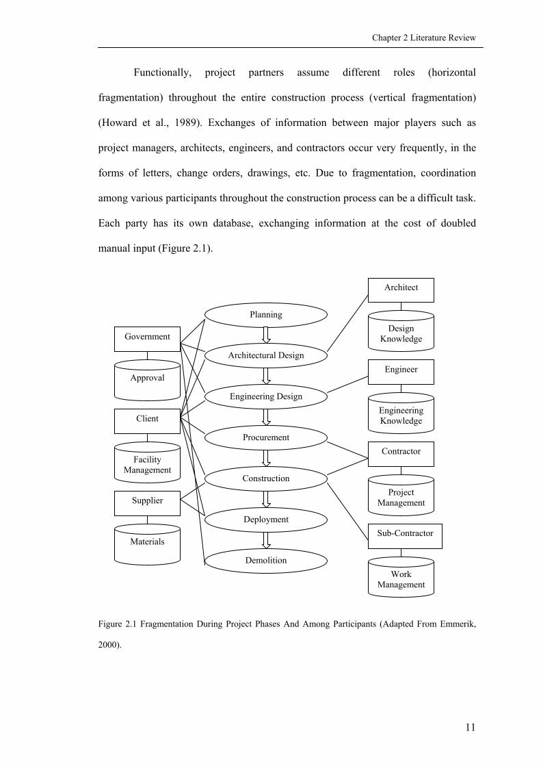
Functionally, project partners assume different roles (horizontal
fragmentation) throughout the entire construction process (vertical fragmentation)
(Howard et al., 1989). Exchanges of information between major players such as
project managers, architects, engineers, and contractors occur very frequently, in the
forms of letters, change orders, drawings, etc. Due to fragmentation, coordination
among various participants throughout the construction process can be a difficult task.
Each party has its own database, exchanging information at the cost of doubled
manual input (Figure 2.1).
Architect
Planning Design
Knowledge Government
Architectural DesignEngineer
Approval
Engineering Design Engineering Knowledge Client
Procurement Contractor
Facility Management
Construction Project
Management Supplier
Deployment Sub-Contractor
Materials
Demolition Work
Management
Figure 2.1 Fragmentation During Project Phases And Among Participants (Adapted From Emmerik,
2000).
11

Chapter 2 Literature Review
2.2.2 Data Incompatibility
One major problem for information exchange is data incompatibility, which
means that files generated from different applications cannot be read by other
applications. There are three kinds of incompatibility: incompatibility of application
versions; incompatibility of homogenous information; and incompatibility of
heterogeneous information.
Incompatibility of application versions refers to situations when files
generated by a later version cannot be read by the same software of an earlier version.
A company using Office 95, for example, may encounter problem with files generated
by Office XP from another company.
Incompatibility of homogenous information occurs when files of the same
format generated by different software cannot be fully interchanged among one
another. For example, in the Computer Aided Design (CAD) domain, exporting
“.dng” files generated by Microstation to “.dwg” ones by AutoCAD causes partial
information lost. This in turn will cause problems when drawings are exchanged
electronically, since every party may use different software.
Incompatibility of heterogeneous information refers to problems encountered
when files of different formats cannot be exchanged with one another. The
construction industry involves various formats of information, such as CAD drawings
(.dwg, .dng, .dxf), office documents (.doc, .xls, .ppt) and other textual documents
(.pdf, .txt), images (.jpg, .gif, .tif, .bmp), 3D (3-Dimentional) models (.3ds), movies
(.mov, .avi), webpages (.html, .asp), emails (.eml), etc. Incompatibility of
heterogeneous information leads to data re-input from one system to another, reducing
accuracy and efficiency. Therefore, it is the focus of many integration researches.
12

Chapter 2 Literature Review
2.3 INFORMATION INTEGRATION
There are many perspectives of integration against fragmentation and data
incompatibility (Figure 2.2). On top of the hierarchy are managerial and technical
integration (Dias, 2001; Fischer, & Kunz, 1995; Haag, Cummings, & Dawkins, 1998).
Managerial integration puts an emphasis on the collaboration among the value chain
(Barua, Chellappa, & Whinston, 1996; Castle, 1999). Technical integration focuses
on data interoperability of software applications that supports different disciplines
(Zhu, 1999).
Information Integration
Managerial Integration
Technical Integration
Back-end Integration
Front-end Integration
Document-based
Meta-data Based
Figure 2.2 Hierarchy Of Information Integration.
2.3.1 Managerial Integration
It is argued that the AEC industry is not able to use IT strategically because
companies view IT as a technological issue, rather than a business one (Betts, 1999).
The subject of Computer Supported Collaborative Work (CSCW) is concerned with
13

Chapter 2 Literature Review
the strategic use of IT from the management perspective (Löwnertz, 1998). Two sub-
topics on CSCW are discussed here: process redesign and concurrent engineering.
2.3.1.1 Process Redesign
Process redesign of organizational functions and operations is defined as “the
fundamental rethinking and radical redesign of business processes to achieve dramatic
improvement in critical, contemporary measures of performances, such as cost,
quality, service, and speed” (Hammer and Champy, 1993).
Task Intra
FunctionCross
FunctionOutside
Business Whole
Business
Process Redesign
Return on Investment
TTeecchhnnoollooggyy--DDrriivveenn VViissiioonn
((1100--2255%% RReettuurrnn))
Tactical Business Vision
(300% Return)
Strategic Business Vision
(1000% Return)
Figure 2.3 Process Redesign And Return On Investment (Source: Fallon, 2000).
Hammer (1996) claims that problems lie not in the performance of individual
tasks and activities, but in the processes, i.e., how the units fit together into a whole.
The realization of dramatic improvement of business performance through
organizational process redesign rather than tactical and operational improvement calls
for new methodology to handle business operation, among which is the extensive
14

Chapter 2 Literature Review
applications of IT. By changing the ways people work and taking advantages of IT to
deliver competitive advantage, business fortunes increase dramatically rather than
incrementally, as depicted in Figure 2.3 (Betts, 1999; Fallon, 2000; IDC, 2000).
2.3.1.2 Concurrent Engineering
The concurrent engineering concept is defined as a systematic approach to the
integrated concurrent design and construction of products, the consideration of related
downstream aspects, and the elimination of non-value adding activities (Abduh,
2000). It aims at promoting collaborative teamwork by integrating all project
participants that plan, design, produce, maintain, and support the project over its life
cycle. Collaboration through the Internet shortens communication time, minimizes
data input error, and improves information quality.
2.3.2 Technical Integration
The purpose of technical integration is to solve the problem of data
fragmentation. Most approaches fall into two categories: the back-end and the front-
end integration. The back-end integration happens at a low system level, so that data
and information generated within the same database system do not have the data
fragmentation problem. The front-end integration happens at the “front” of different
system that does not share anything at the system level. It is based on sharing a
neutral data format that is independent of any system.
15

Chapter 2 Literature Review
2.3.2.1 Back-End Integration
A large group of international model-based projects applies the back-end
integration strategy, which include ATLAS (ATLAS, 1992), RATAS (Björk, 1989;
Penttila, & Tiainen, 1991), CIMSteel (Watson, & Crowley, 1994), COMBINE
(Augenbroe, & Levis, 1991; Dubois, Flynn, Verhoef, & Augenbroe, 1994), ATLAS
(Poyet, 1994), COMBI (Katranuschkov, 1994), and WISPER (Faraj, Alshawi, Aouad,
Child, & Underwood, 2000), to name a few. They present the building project as a
"process of activities" leading to the elaboration of a "product". Based on the focus,
these can be classified as “product modeling” and “process modeling” (Zhong, 1998;
Hughes, 1991). Both attempt to produce computer implementable data models
expressed by formal representation such as IDEF0, IDEF1x, NIAM and EXPRESS
(Ameziane, 2000). These projects are relatively large, complex and difficult to
implement. Most of them include pre-defined rigid data structure that is either too
comprehensive for industrial applications, or too inflexible for actual cases.
2.3.2.2 Front-End Integration
Electronic document management systems (EDMS) creates an environment
within which disparate forms of information can be linked together to achieve easy
access and control in the context of a project or organization (Figure 2.4). It addresses
the following aspects of data management (Sun and Aouad, 1999; Löwnertz, 1998):
Efficient location and delivery of documentation; Ability to manage documents and
data regardless of the original system or form; Ability to encompass and integrate
with existing computer or paper based systems in the context of a construction
project; Control of access, distribution and modification of documents, with the
16

Chapter 2 Literature Review
ability to mirror existing company procedures; Provision of tools to edit documents
and add markup information whatever the source of the document; and Support of
both paper-based and digital documentation, including importing of scanned
documents.
EDMS manages information in the document level, in which documents are
regarded as black boxes. The system has no knowledge about the internal structure or
content of the document. It manages a document only based on the meta-data
attached to it. EDMS is a type of shallow front end integration.
Figure2.4 Configuration Of A Document Management System (Souce: Sun and Aouad, 1999).
The other strategy, Data Markup Integration (DMI) through a third party, i.e. a
neutral data format, is arising with the development of international standardizations
(e.g., STEP, IFC,) and the emergence of the eXtensible Markup Language (XML). It
regards a document as the information container so that data is marked up and can be
extracted from within (Zhu, Issa, & Cox, 2001). This strategy is preferable because of
its simplicity and extensibility.
17

Chapter 2 Literature Review
DMI is simple because it does not involves a complex database level structure
to accommodate everything, which is most back-end integrations trying to do. At the
same time, DMI is extensible since the schema of XML can be defined according to
specific domain knowledge. For example, there are ebXML for ebusiness (ebXML,
2001), MathXML for mathematics, and ifcXML for the AEC industry (Liebich, &
Adachi, 2000). It also allows designers to easily create their own customized tags to
include new requirements.
2.4 INTERNETWORKING AND APPLICATION
Internetworking is a comprehensive term for the concepts, technologies, and
generic devices that allow people and their computers to communicate across
different kinds of networks.
2.4.1 Internetworking Technology
Internetworking, which is commonly called internet, actually includes
Internet, Intranet and Extranet. The Internet is a global connection of special function
computers called “servers” that are linked to share information with the user
computers called “clients”. Originating from 1960s, the Internet became popular in
1990s, with the application of user-friendly browsers, search engines, support
languages, and the proliferation of Internet Service Providers (Lucas, 1997).
An Intranet is a mechanism for sharing information and delivering data from
corporate databases to the local area network (LAN) desktop (Barkowski, 1999).
Intranets use Web technology and are restricted networks for intra-organizational
18

Chapter 2 Literature Review
information and resource sharing. Advantages are full control of information against
external attacks, and sharing IT facilities, e.g. printers, scanners, etc.
An extranet is a private network that uses the public telecommunication
system to securely share part of a business's information or operations with suppliers,
vendors, partners, customers, or other businesses. An extranet can be viewed as part
of a company's intranet that is extended to users outside the company (Whatis, 2002).
In the AEC industry, an extranet links the owner, designer and contractor into a
project specific Website for information sharing. The use of Extranet enhances the
accessibility of project documentation to all participants, imposes cohesion and order
on the massive amounts of project data, thus reduces cost and shortens project
duration.
2.4.2 Internetworking Applications
Internetworking is ideal for the AEC industry since it is cheap, widely
available and not too difficult to use. Currently there are four types of Web-based
applications for the AEC industry: the fee-based project management service; the
build-it-yourself solutions; the Web-enabled software (Zhu, 1999); and the national or
regional wide Web platforms (Scherer, 2000).
The subscription fee-based project management services are provided by
professional IT companies called Application Service Providers (ASPs). Examples
are Autodesk (Autodesk, 2001), Citadon (Citadon, 2002), Constructw@re
(Constructware, 2001), to name a few. Benefits include low implementation cost, few
IT expertise needed, easy application upgrade, simple system requirements.
19

Chapter 2 Literature Review
Limitation is that information is under the control of a third party. Major concerns are
information security, data accessibility, and service quality.
The build-it-yourself solutions are suitable for extremely large companies, so
that they can tailor the application to best fit their business environment and maintain
their own business style. The limitations are obvious: lots of investment, outsourcing
and long development cycle. Example is Bechtel (Bechtel, 2002), etc.
Web-enabled software refers to the whole-set Web-based solution that are
bought and maintained by construction companies, which is a balance of the former
two. It reduces the need for outsourcing, shortens the development cycle and, at the
same time, retains the sensitive information under the supervision of in-house
technical staffs. Limitations are higher initial cost, and greater know-how
requirement of the staff. Example is TurnerTalk (Turner, 2003), etc.
The national or regional wide Web platforms provide the super structure to
enable multiple functions to be accessed via a single interface. It has broader scope
than the last three solutions, and also involves more difficulty of integration among
sub-divided functional modules. Examples are the CORENET project in Singapore
(CORENET, 2001), and the ISTforCE project in Europe (Cerovsek and Turk, 2000).
The Construction and Real Estate Network (CORENET) is part of Singapore
IT2000 plan for the construction industry that acts as the infrastructure to integrate the
processes of design, procurement, building, and maintenance. The CORENET project
has several components as shown in Figure 2.5 (CORENET, 2001): Integrated
Submission systems (e-Submission, and e-approval); Integrated plan checking; BP
expert; IT standards (CAD and classification standards); Legal framework for data
20

Chapter 2 Literature Review
security; eBusiness enablers (eProcurement pilot and project Website pilot); and
Information services (eCatalogue, product details library).
Figure 2.5 Components Of The CORENET Project (Source: CORENET, 2001).
Intelligent Services and Tools for Concurrent Engineering (ISTforCE) is a
European framework project (Cerovsek and Turk, 2000). Its goal is to design a Web-
based services platform through which engineers at a given design or consulting
company will access the services on the Internet and collaborate in real time. It aims
at creating infrastructure on which real construction companies and virtual teams of
construction companies can rent and customize services on a project by project basis,
and where providers of engineering services can market their products.
The first solution, fee-based project management service, is the focus of this
study. It facilitates the inter-organizational information sharing with affordable price,
professional services, which sets the trend for Web-based project management. More
importantly, it helps to reduce unnecessary data structure variety and standardize
Web-based information exchange processes. Chapter 3 will discuss in details the
features of ASPs, as well as benefits and obstacles of its adoption.
21

Chapter 2 Literature Review
2.5 STANDARDIZATION
Standardization efforts in the area of product modeling have been related to
two projects: the STEP (Standard for the Exchange of Product model data) by the
International Standards Organization (ISO); and the IFC (Industry Foundation
Classes) delivered by the International Alliance for Interoperability (IAI).
2.5.1 Standard For The Exchange Of Product Model Data
STEP (STandard for the Exchange of Product model data) is the informal
name of the ISO 10303 standard series: Industrial automation systems – Product data
representation and exchange, developed by ISO TC184/SC4. It was initiated by the
manufacturing industry and adopted by the AEC. STEP intends to create an
international standard for computer-based description and exchange of the physical
and functional characteristics of products throughout their life cycle.
The development strategy of STEP is based upon the concept of Application
Protocol (Santos and Hernandez, 2000). Within the building construction sector, four
different work items including conceptual schemes are in progress. These work items
are: Building Element Using Explicit Shape Representation (AP 225); Building
Construction Core Model (Part 106); Building Structural Frame: Steelworks (AP
230); and Building Services: Heating, Vent. and Air Condition (AP228).
2.5.2 Industry Foundation Classes
IFC is delivered by IAI in parallel with STEP. IAI, started in 1994, is an
international organization of over 600 AEC/FM companies and software vendors.
22

Chapter 2 Literature Review
IFCs are universal codes for modeling building elements, which are shared by
different kinds of software applications throughout the life cycle of buildings.
The IFC specifications have been developed following the STEP based
implementation methods, especially the EXPRESS definition language (ISO 10303-
11:1994) (ISO, 1994a) and the STEP physical file format (ISO 10303-21:1994) (ISO,
1994b).
The IFC model uses a strict referencing hierarchy. There are four conceptual
layers (Figure 2.6). The first and lowest layer is Resource Classes, which are used by
classes in the higher levels. The second layer provides a Core project model,
containing the Kernel and several Core Extensions. The third layer is the
Interoperability layer, which provides a set of modules defining concepts or objects
commonly across multiple application types or AEC industry domains. These three
layers together define the platform layer. The fourth and the highest layer is the
Domain/Applications Layer, which provides a set of modules tailored for specific
AEC industry domain or application types. This is also called extensible layer,
because the schemas on this layer are extensible and new schemas can be defined on
top of the platform for applications.
2.6 CONCEPTUAL MODELING METHODOLOGIES
There are two major conceptual modeling methodologies in the construction
IT application domain: The STEP methodology, and the UML methodology.
23

Chapter 2 Literature Review
Figure 2.6 IFC2x Architecture (Source: IAI, 2000).
2.6.1 The STEP Methodology
The development strategy of STEP is based upon the concept of Application
Protocol (AP), which guaranties the independence of information requirement
specifications from any particular implementation within an application domain
(Poyet, 1995; Santos and Hernandez, 2000). The process of developing an AP
includes the following activities:
• Development of Application Activity Models (AAMs);
• Development of Application Reference Models (ARMs);
• Development of Application Interpreted Models (AIMs).
24

Chapter 2 Literature Review
Application Activity Models (AAMs) are the scope statement of the domain of
the planned AP domain. It describes the application context and functional
requirements. AAMs are described by process models using IDEF01 diagrams.
Application Reference Models (ARMs) describe the information requirements
and constraints for the specific AP. ARMs document the required data and
relationships and are normally specified using EXPRESS-G2 (ISO, 1994a), IDEF1x3,
or NIAM4 (Nijssen, et al., 1989).
The Application Interpreted Models (AIMs) specify the interpretation of the
Integrated Resources to satisfy the information requirements of the AP described by
the ARM. The AIMs are also specified using the EXPRESS language.
Although the STEP methodology has been used in the AEC domain for around
20 years, Santos and Hernandez (2000) pointed out its limitations, which are:
• Inconsistency among the models, especially between the AAM and AIM;
• High modeling knowledge requirements in order to interpret among the
models, which add barriers to the communications among domain experts;
• Not fully computer oriented, which adds difficulty to the software
development process.
Santos and Hernandez (2000) also proposed the use of a single modeling
method for AP’s development, based on the recent and powerful modeling language –
UML. They are mapping the STEP AP to UML for the AEC sector.
1 IDEF0 stands for ICAM Function Definition Method. 2 EXPRESS-G is the graphic expression of EXPRESS, a language to express models in the STEP project. 3 IDEF1x also stands for ICAM Function Definition Method. 4 NIAM stands for Nijssen's Information Analysis Method.
25

Chapter 2 Literature Review
2.6.2 The UML Methodology
Unified Modeling Language (UML) is a language for systems engineering
(OMG, 2000). It is developed primarily from two of the most popular modeling
formalisms for object-oriented modeling, OMT and Booch. It is chosen for this study
because the language is rapidly being established as a de facto standard for object-
oriented modeling, and has been adopted as an international standard within the OMG
(Object Management Group) that develops the Common Object Request Broker
Architecture. The technical details of UML will be discussed in Chapter 5.
2.7 EXTENSIBLE MARKUP LANGUAGE
Both XML (eXtensible Markup Language) and HTML (Hyper-Text Markup
Language) are sub-sets of the mega-language SGML (Standard Generalized Markup
Language). SGML is an international information coding standard developed by ISO
in the early 1980s (Van Herwijnem, 1994). There are three types of tagging schemas
in SGML, namely format tagging, structure tagging, and content tagging. HTML and
XML apply format tagging and content tagging respectively. Since SGML is too
complicated for commercial use, HTML prevailed as a simplified meta-language to
depict Web contents in the 1990s. However, lack of information structure creates
difficulty for dealing with large amount of information and precisely locating the
needed one (Zhu, 1999).
The limitations of SGML and HTML can be overcome by XML. Instead of
focusing on the presentation of information, XML focuses on the semantics of
information that is displayed, and separates the content of a document from its
presentation. XML is “extensible” because it allows designers to create their own
26

Chapter 2 Literature Review
customized tags, enabling definition, transmission, validation, and interpretation of
data between applications and between organizations. In this way, XML provides
more user-friendly applications by allowing users to tailor presentations according to
their ad hoc needs. XML 1.0 is the specification that defines what "tags" and
"attributes" are. Beyond XML 1.0, "the XML family" is a growing set of module,
which include XSD (XML Schema Definition), XLink, XPointer, XFragments, XSL
(XML Stylesheet Language), DOM (Document Object Model), XML Schemas part 1
and 2, etc (W3C, 2001).
In the AEC industry, at least three consortiums are working on domain
specific schemas: the bcXML (building and construction XML) developed by the
European project eConstruct; the aecXML (architectural, engineering and
construction XML) initiated by Bentley Corp, USA; and the ifcXML (industry
foundation classes XML) developed by the IAI.
2.7.1 BcXML
BcXML is the outcome of the European project eConstruct. The goal is to
develop the standards to support communication related to the procurement of
materials, components, assemblies, documents, systems, services and equipments
over national borders in Europe (Tolman et al, 2000; 2001). It provides the European
building construction industry with a powerful and low cost communication
infrastructure in three aspects: Supporting eCommerce between users and suppliers
of building materials, components, systems and services; Integrating with eCommerce
and Design/Engineering applications; and Supporting virtual market places over the
borders of the individual European member states.
27
Chapter 2 Literature Review
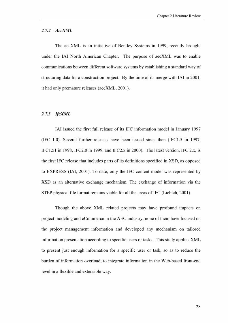
2.7.2 AecXML
The aecXML is an initiative of Bentley Systems in 1999, recently brought
under the IAI North American Chapter. The purpose of aecXML was to enable
communications between different software systems by establishing a standard way of
structuring data for a construction project. By the time of its merge with IAI in 2001,
it had only premature releases (aecXML, 2001).
2.7.3 IfcXML
IAI issued the first full release of its IFC information model in January 1997
(IFC 1.0). Several further releases have been issued since then (IFC1.5 in 1997,
IFC1.51 in 1998, IFC2.0 in 1999, and IFC2.x in 2000). The latest version, IFC 2.x, is
the first IFC release that includes parts of its definitions specified in XSD, as opposed
to EXPRESS (IAI, 2001). To date, only the IFC content model was represented by
XSD as an alternative exchange mechanism. The exchange of information via the
STEP physical file format remains viable for all the areas of IFC (Liebich, 2001).
Though the above XML related projects may have profound impacts on
project modeling and eCommerce in the AEC industry, none of them have focused on
the project management information and developed any mechanism on tailored
information presentation according to specific users or tasks. This study applies XML
to present just enough information for a specific user or task, so as to reduce the
burden of information overload, to integrate information in the Web-based front-end
level in a flexible and extensible way.
28

Chapter 2 Literature Review
29
2.8 SUMMARY
This chapter provides an overview of the theories and technologies related to
the study. Two major problems of IT applications in the AEC industry are identified
as fragmentation in general and data incompatibility in specific. Integration efforts
have been made in both managerial and technical aspects but this study focuses on
front-end technical integration applying DMI. Extranet is the Internetworking
technology that enables project specific communication and collaboration in the AEC
industry, preferably under the ASP model. Standardization efforts world wide are
reflected in two major projects, namely the STEP and the IFC.
Two major conceptual modeling methodologies are discussed, namely the
STEP approach, and the UML approach. UML is selected as the modeling tool for
this research because it is simple, intuitive, and widely accepted by the IT domain to
facilitate the transfer from conceptual model to software development.
XML is a meta-language that enables Web-based data exchange. BcXML,
aecXML and ifcXML are the developing domain schemas for the AEC industry.
However, since they only address physical components and domain specific
information but not construction documents, a new approach has to be develop to take
into account how information should be tailored according to a particular task or user,
which is the task of this study.

CHAPTER 3 FUNCTIONAL REQUIREMENTS OF ASPS
3.1 INTRODUCTION
The last chapter introduces internetworking technology and its applications in
the AEC industry. Web-based collaborations provided by the ASPs are in favor since
it is economical and technically easy to implement. More importantly it helps to
standardize Web-based information exchange processes. This chapter describes the
history and development of ASP, the current features and the features for future
development. Adoption benefits and obstacles are also analyzed.
3.2 HISTORY OF ASP DEVELOPMENT
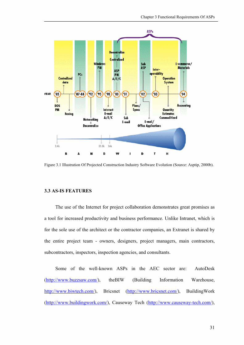
Figure 3.1 shows the IT development for construction. ASP evolved in 1998
and boomed in 2000. The first project Web solutions emanated from the concept of
FTP servers. Project Website solutions vary in standard and capabilities; from
solutions simply for static homepages and options for up- and download, to advanced
solutions with dynamic update of searchable contents and integrated workflow
management tools (Hartvig, 2001a).
A project specific Website is a private Website on an Internet server, where
parties involved in a project can share documents, communicate, and carry out
information related tasks in the collaboration processes. The most important
advantage of ASP is to support process re-engineering through timely
communication.
30
Chapter 3 Functional Requirements Of ASPs
Figure 3.1 Illustration Of Projected Construction Industry Software Evolution (Source: Asptip, 2000b).
3.3 AS-IS FEATURES
The use of the Internet for project collaboration demonstrates great promises as
a tool for increased productivity and business performance. Unlike Intranet, which is
for the sole use of the architect or the contractor companies, an Extranet is shared by
the entire project team - owners, designers, project managers, main contractors,
subcontractors, inspectors, inspection agencies, and consultants.
Some of the well-known ASPs in the AEC sector are: AutoDesk
(http://www.buzzsaw.com/), theBIW (Building Information Warehouse,
http://www.biwtech.com/), Bricsnet (http://www.bricsnet.com/), BuildingWork
(http://www.buildingwork.com/), Causeway Tech (http://www.causeway-tech.com/),
31

Chapter 3 Functional Requirements Of ASPs
Citadon (http://www.citadon.com/), Constructware (http://www.constructware.com/),
Cosential (http://www.cosential.com/), eBuilder (http://www.e-builder.net/), eRoom
(http://www.eroom.com/), Meridian (http://www.mps.com/), Primavera
(http://www.primavera.com/). These ASPs develop the core applications for Web-
based project management in-house. Some re-sell their technologies or form business
alliances with other parties.
Services and features provided by the ASPs vary greatly. The features discussed
here are collected from various sources, including the introductions of the commercial
ASPs (AutoDesk, 2001; Bricsnet, 2002; BIW, 2002; Buildingwork, 2002; Citadon,
2002; Constructware, 2001; Cosential, 2002; eRoom, 2002; Meridian, 2002;
Primavera, 2002), third-party analysis on ASP development (Smith, 2000; Asptip,
2000a; ProjectAims, 2002a; 2002b), and academic research findings (Hartvig, 2001b,
2001c; Cohen, 2000; Castle, 1997; Abduh, 2000). The list of features that ASPs
currently provide is divided into 7 categories: general system; document management;
workflow management; administration; user centric workplace; team communication;
and ASP server performance. Appendix I provides a comprehensive list and detailed
descriptions of every feature that is currently available.
The category of general system includes some general features that do not fall
into any specific category, such as public project webpages; project cloning; links to
AEC industry information services; and Web camera on site, etc.
Document management contains features that manage files generated by various
applications, which include remote viewing, printing and commenting of files through
Web browsers; document revision control with file locking and check-in/check-out;
handling external references for CAD drawings; and digital approval, etc.
32

Chapter 3 Functional Requirements Of ASPs
A workflow is a process that involves collaboration among project players, e.g.,
the process of approving a change. Standardized workflow management is achieved
through the use of Web-based forms and templates. Other features include integration
with e-procurement; issues linking; automatic generation of customizable reports; and
tasks management, etc.
Administration is done by the so called Chief Information Officer (CIO), whose
duty is to manage the project Web throughout the whole process of Web site
utilization. The features for administration include access control; auditing; set-up of
project Website templates, workflow and other project specific business logics; and
task allocation, etc.
A user centric workplace is similar to the desktop of an operation system, such
as Microsoft Windows. It can be customized according to the user’s working habits.
These features include customizable interface; headlines page; multiple languages
support; multi-project support; drag-n-drop, and right-click, etc.
Team communication is Internet enabled communication, such as email,
instance messaging, discussion forum, online conferencing, etc. These features
provide supplementary information for formal communication. Compared to
traditional communication means such as phone call, fax, and face-to-face meetings,
the team communication features have the advantages of low cost, fast speed and
traceable record.
Server performance is a very importance factor for evaluating the quality of
ASP services. Since all services are Web-based, the availability of project Website,
the browsing speed, the file transfer speed, the data security against external hackers,
all these factors will have significant impacts on the project team’s activities.
33

Chapter 3 Functional Requirements Of ASPs
3.4 TO-BE FEATURES
The to-be features are developed based on related research projects and
literature about the current and future ASPs. In the ISTforCE project (Intelligent
Services and Tools for Concurrent Engineering, Referred to Chapter 2), Cerovsek and
Turk (2000) stated that a prototype Internet desktop system for engineers should have
the following 5 requirements: it should be open enough to integrate with other service
or tools, customizable to persons, customizable to projects, scalable, and extendable.
In the GLOBEMEN project (Global Engineering and Manufacturing in
Enterprise Networks), Hannus and Kazi (2000) pointed out 5 managerial
requirements: standards for external communication; short set-up time and low cost of
the common working environment; short learning time of common tools; protection
of proprietary knowledge; and support division of responsibilities between team
members.
Also in the GLOBEMEN project, Laintinen and et al. (2000) stated the
following user centered requirements: The users should be able to access and update
the required information efficiently. Access to the ASP should be controlled
according to the role of each individual in the process. The users should be provided
with functionality to: search for valuable information in various sources, such as the
Web, Intranet and local drives; quickly and easily obtain the information and
knowledge that is relevant to their tasks and responsibilities; synthesize different
pieces of information and organize existing knowledge; view the well-organized
information from different perspectives depending on their roles in the process;
accumulate acquired knowledge orderly for future usage; and generate reports for
decision making.
34

Chapter 3 Functional Requirements Of ASPs
Based on the study above, the to-be features of a Web-based construction
project management system have been developed and classified into 8 categories:
• Time and cost consideration;
• Integration;
• Searching for information;
• Knowledge base and intelligence;
• Customizability to persons;
• Customizability to projects;
• Scalability; and
• Others.
3.4.1 Time And Cost Considerations
Time and cost considerations include short set-up time and low cost; and short
learning time of common tools.
3.4.2 Integration
Integration has broad meanings. There are at least three types of integration:
Firstly, integration throughout project life cycle, with company database, and
with project model 1 ; Interoperability through AEC industry-wide standards for
related information, allowing data sharing between any systems used by any project
participant (e.g., STEP, IFCs, aecXML, etc.). 1 A project model contains OOCAD, cost, scheduling and other building information of every building element. It is considered the ultimate way to realize data interoperability among different software applications throughout the project life cycle. OOCAD stands for Object-Oriented Computer-Aided Design.
35

Chapter 3 Functional Requirements Of ASPs
Secondly, integration with solid modeling, virtual reality, and other visual
technology.
Lastly, integration with the software environment that users are using to do their
jobs, so as to reduce rework. The software environment includes the general office
software (word, spread sheet), design and project management tools (CAD,
scheduling, accounting, invoicing, electronic bid management, task and resource
scheduling, and online tracking of plans). For example, the automatic retrieval of
meta data resided in word and excel files will reduce re-entering meta data when
uploading files. Integrating contacts and calendars with users’ local system will avoid
redundant input of contacts and tasks.
3.4.3 Intelligent Search For Information
Intelligent search for information means a quick access to and the efficient
updating of required information; searching for valuable information in various
sources, e.g., the project Web, the Internet, LAN and the local computer.
3.4.4 Knowledge Base
Knowledge base means accumulating acquired knowledge for future usage;
incorporating decision support system, supporting what-if analyses; and generating
reports for decision-making.
36

Chapter 3 Functional Requirements Of ASPs
3.4.5 Customizability To Persons
Customization allows for personalized interfaces; displays information from
different perspectives tailored to a user's role.
3.4.6 Customizability To Projects
Customization to projects means that the ASP solution is suitable for all kinds of
projects varied in size, type and degree of complexity.
3.4.7 Scalability
Scalability means the ASP solution is usable for both low and high speed
Internet connection, compatible with files generated by software of different versions,
and extensible to accommodate developing applications.
3.4.8 Others
Other useful features include: protection of knowledge proprietary, and
supporting division of responsibilities among team members.
3.5 ASPS IN SINGAPORE
By Year 2002, 5 major local ASPs are in use in the Singapore construction
market: Cyber-IB (http://www.cyberib.com/), CXHub (http://cxhub.com/),
HDBuilders (http://www.hdbuilders.com/), icFox (http://www.icfox.com/), and
icx123 (http://www.icx123.com/). Among them, icFox forms a strategic partnership
37
Chapter 3 Functional Requirements Of ASPs
with Citadon and applies its collaboration solution; while Cyber-IB partners with
AutoDesk. The icx123 and CXHub are mainly information providers, who do not
focus on project collaboration. HDBuilders has a local technology partner, who
develops Web-based management solution targeting at the local contractors only.
HDBuilders.com, the subsidiary of Singapore Housing and Development Board,
extends its open bidding system (e-bidding) of public projects to main tenders, who
can submit as many bids as required to arrive at a competitive bid. The Singapore
local portals provide various services in e-commerce, e-project management and
information exchange for the local construction industry. Their effectiveness and
impacts on the construction industry are yet to be determined.
3.6 ASP BENEFITS
The main advantages of applying IT are improved productivity and business
performance. Productivity refers to time, cost, quality, and added-value, etc.
Business performance refers to communication, customer satisfaction, and
competitiveness, etc. Besides, there are other advantages, such as availability of
information and process redesign. This section reviews the benefits of applying ASP,
and indicates that these general benefits also applied to the DMI system.
A client impact study carried by Constructware summarized ASP benefits in the
following areas (Constructware, 2001): increasing productivity; improving risk
management; reducing costs; and gaining a competitive advantage.
Cohen (2000) summarized five types of benefits mainly from the productivity
prospect, which include: quality improvements; efficiency improvements; time
improvements; new sources of revenue; and reduced direct costs.
38

Chapter 3 Functional Requirements Of ASPs
A more detailed study by PricewaterhouseCoopers indicates the benefits for
applying ASP solutions include (Wesek, Cottrez, and Landler 2000): improving
project progress communication; providing real time access to information and
reducing the response time for RFI, change orders and specifications clarification;
shortening of the project life cycle; increasing ownership and accountability; and
improving record keeping and documentation.
In summary of the above findings and other statements by the ASPs, the major
benefits of applying Web-based project management can be classified into 5
categories (Wesek, Cottrez, & Landler 2000; Cohen, 2000; IDC, 2000;
Constructware, 2001; BIW, 2002; Bricsnet, 2002; Citadon, 2002):
• Improved communication;
• Reduction on project life cycle time;
• Reduction on cost;
• Accountability and records; and
• Gaining competitive advantages.
3.6.1 Improved Communication
There are two factors for the consideration of improved communication: the
quality of communication, and the overall time saving in the progress of
communication.
Better quality of communication is achieved because Web-based project
management allows users to collaborate with other project team members for better
communication in an opened environment. Once they log in to the project Web, all
39

Chapter 3 Functional Requirements Of ASPs
information accessible is right there for their usage. In addition, ASPs enable long-
distance cooperation among project participants.
Time saving in progress communication is achieved because time spent on
general project communication is shortened, keeping all members of the project team
informed of the status of the project, issues and other information relevant to ensure
project’s timely completion. Examples of activities include: meeting minutes, action
items, creating filters/securities, project schedule updates, etc. Thirty to sixty percents
of time saved is expected by professionals on project team in communicating project
progress (Wesek, Cottrez, and Landler 2000).
3.6.2 Reduction On Project Life Cycle Time
Reduction on project life cycle time is achieved by three means: availability of
information, time reduction of workflows, and time saving in data searching.
Information is available 24 hours a day, 7 days a week. Real-time availability of
information reduces waiting time and searching time for information.
Turn-around time of workflows, e.g., RFI, VO (Variance Order), is shortened in
submitting a query and receiving a response from another member of the project team.
Wesek, Cottrez, and Landler (2000) examined that 30%-60% reduction on turn-
around time can be achieved.
Time saving in document creation, filing, searching for documents on
specifications and elements of design can be up to 50% (Wesek, Cottrez, and Landler
2000).
40

Chapter 3 Functional Requirements Of ASPs
3.6.3 Reduction On Cost
There are many aspects of reduction on cost, such as immediate and long term
cost savings, improved procurement process and increased revenue by earlier
completion of project.
Immediate cost reduction of printing, faxing, mailing, courier services,
travelling can be perceived on average 20%-30% of actual costs saved (Wesek,
Cottrez, and Landler 2000).
Long-term cost savings are achieved through reductions in mistakes and re-
work, and by avoiding unnecessary project delays.
Improved procurement process provides the opportunity to search for best deals
and purchasing supplies online.
The time saving advantage leads to earlier completion of project, which in turn
generates increased revenue. Tenants are able to occupy site ahead of schedule and
begin paying rent sooner than anticipated. Project team can begin working on another
revenue and fee generating project.
3.6.4 Accountability And Records
Accountability and records refers to improved documentation, which include
increased transparency of documents; increased ownership and responsibility of
project parties; better documentation of project life cycle history; and decreased legal
risk and prevention of construction claims.
41

Chapter 3 Functional Requirements Of ASPs
Increased transparency of document means that any team member can view all
accessible project information at any time.
The ownership and responsibility of project parties are increased because tasks
allocated are clearly documented in a central repository, which is accessible to every
member.
Better documentation of project life cycle history means project history and life
cycle is documented and succinct audit trail is available for reference.
Legal risk is decreased and construction claims are minimized because there is
less opportunity to shift responsibility and take legal recourse. Should disputes arise,
the audit trail feature can help identify exactly when particular items of information
were created, discussed and amended.
3.6.5 Gaining Competitive Advantages
Competitiveness is gained by established standards, accumulated knowledge,
integrated information, better and faster decision-making, and improved partner
relationships and customer satisfaction.
Establishing Standards ensures that data created by one project participant can
be used and re-used by others without conversion or reformatting.
Knowledge is carried forward to future projects, because features are configured
and customized to address the unique business processes of each enterprise, providing
standard templates that leverage industry best practices, encapsulating lessons learned
on previous schemes, promoting continuous performance improvement.
42

Chapter 3 Functional Requirements Of ASPs
Web-based project management provides integration and data exchange with
other enterprise systems, such as project accounting, allowing firms to leverage their
investments in those systems while ensuring that all systems are on the same page at
the same time.
Better and faster decision-making is achieved since real-time information
improves forecasting and decision-making.
Improved partner relationships and customer support is achieved since Web-
based project management helps to develop trust with up-to-date information and
transparent process management.
3.7 OBSTACLES TO ADOPTION OF ASP
According to Castle (1999), there are 4 categories of obstacles for adopting
ASPs:
• Economic considerations;
• Organizational changes;
• Lack of ASP standards; and
• Other obstacles.
3.7.1 Economic Considerations
Economic considerations concerns about the uncertainty of return on
investment. Although there has been many surveys showing overall cost reduction
and performance improvement, firms are slow to adopt ASP, not only because of the
43

Chapter 3 Functional Requirements Of ASPs
high investments in hardware, software, services and training, but also of
organizational investment such as process redesign.
3.7.2 Organizational Changes
Organizational changes include leadership and consensus; balance of power;
team composition; and trust development.
Effective implementation of ASP requires leadership from the client, and
consensus all parties involved in the project. Although building owners consider the
ultimate beneficiaries of the building process and the most effective advocates for the
ASP, most of them do not recognize the potential benefits of ASP, nor to make it a
requirement for participation in the project.
Applying ASP potentially changes the current balance of information power,
shifting more power to the managers. Project information flows are much more
transparent. Owners can track minute-by-minute activity of designers and
construction contractors. General contractors can track minute-by-minute activity of
their subcontractors. It has been suggested that to alleviate such concerns, an
independent outside party (project information manager) be appointed to manage the
project data.
A typical building process consists of several major stages: project definition,
design, construction and operation. Each stage may involve a different set of
specialized firms. Each new comer has to adjust to a new working relationship. In
the nature of the building process, the opportunities for learning and efficiency gains
that arise from stabilizing the work routine and perfecting repetitive tasks are limited.
44

Chapter 3 Functional Requirements Of ASPs
Many people concern about applying ASP will only increase repeating information
input, since they have to put information in the local system as well as the project
system.
The trust on ASPs cannot be achieved without difficulty. Since mission-critical
data are placed in the hands of the ASPs, it brings great concerns if the ASP fails to
stay in business throughout the life of the project. Moreover, a user will completely
lose contact with the project information in case he or she cannot be connected to the
ASP.
3.7.3 Lack Of ASP Standards
Lack of ASP standards arises from the competitions of the various ASP portals
and lack of dominant players in the AEC industry.
For the AEC industry, the IT vendors with the largest market share are also the
most attractive to potential users. As AutoCAD dominates the CAD market, potential
users are more likely to pay more for using this product than the others so as to avoid
compatibility problems. To date, there are still more than a dozen leading figures
pushing to be the leader in the ASP market, although the market has gone through
quite a lot of mergers, acquisitions and failures. Many potential users are reluctant to
commit to an ASP until there are only a few survivors (Chan, & Leung, 2003b).
Inter-organizational information systems have been successful in many
industries, partly because of a major player with sufficient market share to demand
participation of its suppliers. However, in the fragmented AEC industry, such a
45

Chapter 3 Functional Requirements Of ASPs
46
dominant player does not exist. In the near future, the lack of standards is likely to
create a tremendous amount of confusion and slow down the adoption of ASP.
3.7.4 Other Obstacles
Other obstacles include legal barriers; underdeveloped IT infrastructure; and
dissatisfaction with ASP performance.
3.8 SUMMARY
This chapter answers the question of what services ASPs currently provide to
the AEC industry. The chapter reviews the features that current commercial project
Websites provide. There are 7 categories of as-is features, which include general
system; document management; workflow management; administration; user centric
workplace; team communication; and ASP server performance.
This chapter also analyses 8 categories of features under development, which
acts as general research directions of Web-based solutions. These categories are:
time and cost consideration; integration; intelligent search for information; knowledge
base and intelligence; customizability to persons; customizability to projects;
scalability; and others. This chapter also analyses the benefits and obstacles of
adopting ASP.

CHAPTER 4 EMPIRICAL STUDY OF USER REQUIREMENTS
4.1 INTRODUCTION
The last chapter systematically describes many features of ASP solutions. This
chapter evaluates these as-is and to-be features from the user’s perspective. Non-
functional requirements were collected through a Web-based survey conducted in
May 2002. There are 4 categories of as-is features and 4 to-be ones that were
regarded as very useful by the respondents.
While ASP has been in practice for years in Europe and North America, it is not
yet a common practice in the Singapore construction industry. The purpose of the
Web-based survey is to find out the general awareness and requirements towards IT
and ASP of the high educational level professionals in the Singapore AEC industry
(Chan, & Leung, 2003b). This chapter describes the survey in three parts. Firstly,
survey methodology is about the details of how the survey is prepared and carried out.
Secondly, data analysis is about the methods used to analysis the data. Thirdly, overall
findings and analysis are discussed. Appendix II is the Web-based questionnaire.
4.2 SURVEY METHODOLOGY
4.2.1 Sample
Given the fact that Web-based project management is still a pilot study, the
survey focuses on the high educational level professionals in the AEC industry, rather
than on the general practitioners. The invitation email was sent to 284 graduate
students in the School of Design and Environment (SDE), National University of
Singapore. Among the 47 received responses, 30 are complete and valid. The other
47

Chapter 4 Empirical Study Of User Requirements
17 incomplete ones are excluded from the analysis. The response showed that only
several respondents had the experience with ASP. To the majority, however, ASP
was still a new concept. It might be for this reason that 17 potential respondents did
not finish the survey. The graduates are selected because they have enough
construction knowledge, and are among the most likely persons that are actively
involved in IT applications in construction. Their working backgrounds and
experiences are wide enough to represent the sound of the industry in Singapore.
4.2.2 Web-based Survey
The survey was conducted via the Internet (http://annaliang.hypermart.net/). A
pilot survey was conducted with 2 practitioners and 4 graduate students to
troubleshoot the format and content problems in the questionnaire. Results of the
pilot survey were excluded from the final analysis. In the final survey, invitation
email was sent to 284 graduate students in SDE. Their email addresses are collected
from the class roster of graduate courses in SDE and the mailing list of a construction
IT seminar.
The survey was conducted as Web-based rather than paper-based because
webpages, with hyperlinks and java scripts, can explains ideas in an intuitive way via
multimedia. Feedbacks from the pilot survey indicated that if lacking of examples,
the respondents did not fully understand the ASP features explained in plain texts.
With java scripts, definition of a jargon is automatically displayed when a respondent
points to it. With hyperlinks, the Web-based form provides screen shots and animated
demonstrations as live examples to explain almost every ASP feature, which can
never be achieved by paper survey (Figure 4.1).
48
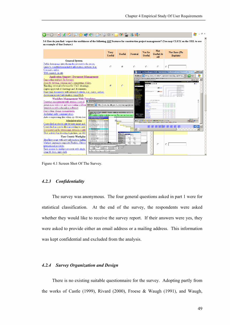
Chapter 4 Empirical Study Of User Requirements
Figure 4.1 Screen Shot Of The Survey.
4.2.3 Confidentiality
The survey was anonymous. The four general questions asked in part 1 were for
statistical classification. At the end of the survey, the respondents were asked
whether they would like to receive the survey report. If their answers were yes, they
were asked to provide either an email address or a mailing address. This information
was kept confidential and excluded from the analysis.
4.2.4 Survey Organization and Design
There is no existing suitable questionnaire for the survey. Adopting partly from
the works of Castle (1999), Rivard (2000), Froese & Waugh (1991), and Waugh,
49

Chapter 4 Empirical Study Of User Requirements
Froese, & Pierre (1996), the author designed the questionnaire specifically for this
study(See survey questionnaire in Appendix II). The survey consists of three parts:
Part 1, general information, consists of 4 general questions of the respondents’
working background. The information is for statistical classification.
Part 2, general uses of IT and networking, consists of 7 questions about the use
of IT and Internet in their practice. The information provides the background of IT
applications in the Singapore construction industry.
Part 3, uses of ASP, consists of 10 questions about the uses and expectations of
ASP in Singapore.
The Web-based questionnaire consists of 7 pages (Figure 4.2):
Page index.html introduces the survey. A click on “Go to Survey Page” will lead
the respondents to the next page.
Page part1.htm, part2.htm, and part3.htm are the three parts of the survey.
When the respondent clicks “Submit”, the cgi script examines whether all required
fields are filled up. If so, it saves the answers, sends an email to the surveyor, and
brings the respondent to the next page. Otherwise, it displays page oops.htm and
urges the respondent to go back and answer all the questions in that page.
Page analysis.htm asks whether the respondent would like to receive the survey
analysis. They can choose to receive by email, by mail or not to receive. For either
of the former two, they are asked to provide an email address or a mailing address
respectively. When the respondent clicks “Submit”, the cgi script examines whether
all required fields are filled up. If yes, it saves the answers, sends an email to the
50

Chapter 4 Empirical Study Of User Requirements
surveyor, and brings the respondent to page thanks.htm. Otherwise, it displays page
oops.htm and urges the respondent to go back and answer all the questions in that
page.
http://annaliang.hypermart.net/
/part1.htm
/part2.htm
/part3.htm
/analysis.htm
/thanks.htm
/oops.htmIncomplete Response
Send Email
Flowchat of Survey
Complete Response
Incomplete Response
Complete Response
Incomplete Response
Complete Response
Figure 4.2 Flowchart Of The Web-Based Survey.
Page thanks.htm indicates that the respondent has completed the survey
successfully.
Page oops.htm is called by the cgi script when the respondent fails to fill up all
required fields. It also urges the respondent to use the “back” button of the Web
browser to go back to that page and redo.
51

Chapter 4 Empirical Study Of User Requirements
4.2.5 Technical Details
The webpages were written with the software of Macromedia Dreamweaver 4.0
and Microsoft Frontpage 2002.
Cgi script was used to process the data. CGI stands for Common Gateway
Interface. It is a standard way for a Web server to pass a Web user's request to an
application program, and to forward the received data to the user (Whatis, 2002). The
cgi script used in this survey is downloaded from bignosebird.com
(http://bignosebird.com/). It is used for two purposes: to process the data collected
from the survey form; and to send the data to the specified email address.
Two java scripts are used in the questionnaire. One is for automatic
presentation of a jargon when the respondent points the curser at it. This script is
downloaded from dynamicdrive.com (http://www.dynamicdrive.com). The other is to
pop up a new window with to show a graphic example when the respondent clicks at a
hyperlink. It is built by javascript.com (http://www.javascript.com/).
4.2.6 Survey Distribution
The survey was distributed to the potential respondents via an invitation email
containing the hyperlink to the survey Website.
4.2.7 Potential Sources Of Biasness
There are several potential sources of biasness in the survey.
52

Chapter 4 Empirical Study Of User Requirements
The survey was set anonymous to free the respondents from concerns of
releasing sensitive and identifiable corporate information. The respondents were
expected to complete the survey at one try. There was no formal mechanism to
prevent double entry except manual check of the respondents’ IP (Internet Protocol)
addresses and responding time. The responses were collected by the cgi script and
sent to the researcher by email. For any complete response, the researcher received 4
emails (for part 1, 2, 3, and report inquiry respectively) from the same IP address
within certain close duration, say half an hour. Theoretically a respondent can try
many times if using different IPs. In reality, however, respondents were bothered by
the length of the questionnaire and some quitted before finishing all three parts,
instead of attempting a second try. These incomplete responses were discharged from
the analysis.
The samples are graduate students in the SDE. Most of them are part time
students by course work, with years of working experience in the Singapore
construction industry. Several of them are full time research students or international
students. These people are among the highly educated professionals in the industry,
and therefore cannot precisely represent the general situation of the Singapore AEC
industry. Their overall attitude in favor of IT is expected to be a bit ahead of the
common practitioners.
To the Singapore construction industry, ASP is still a concept rather than a
common practice. For a pilot study like this, it is impossible to find sufficient
experienced users to complete the survey. The questionnaire is therefore designed to
ask both current and potential users of their experience or expectations towards ASP.
53

Chapter 4 Empirical Study Of User Requirements
The result turns out to be more of expectation than of experience because only a few
respondents have the experience.
However, the biasness is still regarded acceptable because the purpose of the
survey is only to identify the most useful categories of as-is and to-be features of ASP
discussed in Chapter 3.
4.3 DATA ANALYSIS
From the perspective of statistical analysis, the number of observations should
be at least 30 for the sampling distribution to be approximated by a normal
distribution (Levine, Berenson & Stephan, 1999). In this survey, valid responses
happened to be 30, which is deemed to be large enough for meaningful statistical
analysis.
For statistical purpose, a count is converted to percentage by the following
formula:
10030 ⋅= CountPercentage
The survey makes use of scaled responses to capture the subjective evaluations.
For example, the possible answers to question 3.6 included “Very Useful”, “Useful”,
“Neutral”, “Not So Useful”, “Not Useful At All”, and “Not Sure”. To compute the
mean value for the rating, a numeric value is assigned to each response – 5,4,3,2, 1
and 0, with 5 to the highest rating (“Very Useful”) and 1 to the lowest (“Not Useful
At All”), while 0 to “Not Sure”. The same technique is applied to all other scaled
54

Chapter 4 Empirical Study Of User Requirements
responses throughout the survey analysis. The mean scale is calculated by the
following formula:
)()(11∑∑==
⋅=n
ii
n
iii CountCountScaleMeanScale
4.4 OVERALL FINDINGS AND ANALYSIS
4.4.1 Part 1 Respondent Profiles
Among the 30 respondents surveyed, 23.3% are clients, 50% are consultants,
16.7% are contractors and 10% are the academics. None of the respondents is a
supplier or manufacturer (Figure 4.3). It is not clear whether it is due to sampling or
responding bias that suppliers and manufacturers are absent. One possibility is that
they are more interested in e-procurement rather than project collaboration, which is
outside the scope of this study.
Twenty-six point seven percents of the respondents are senior executives, 50%
are construction-related professionals, 13.3% are site management staffs, 10% are
full-time students, but no one is IT-trained (Figure 4.4). Seventy percents of the
respondents have 2 to 10 years of construction-related working experience, 23 % have
been working for more than 10 years and only 7% have less than 2 years working
experience (Figure 4.5). The above findings reveal that the respondents are
construction domain experts, rather than IT experts. They have sufficient working
experience and construction related knowledge to understand the usefulness of IT and
ASP as a tool for their work. Therefore, they are suitable for non-functional
requirement collection, but not functional ones.
55
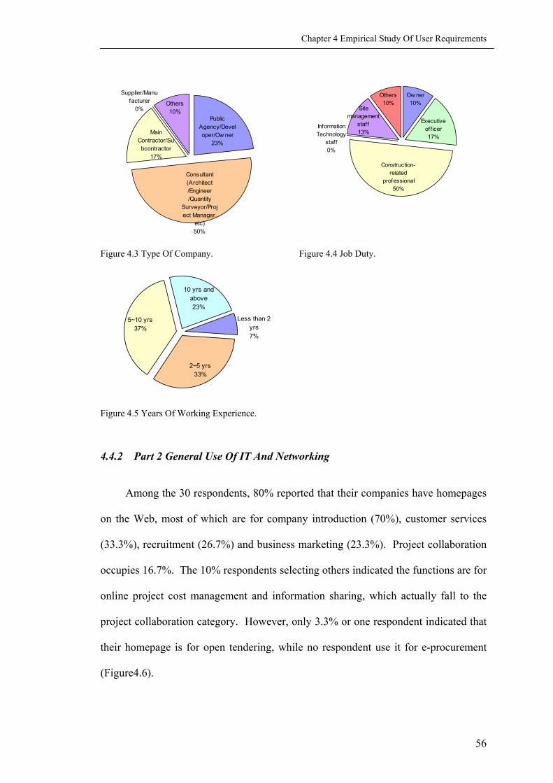
Chapter 4 Empirical Study Of User Requirements
Public Agency/Developer/Ow ner
23%
Others10%
Supplier/Manufacturer
0%
Main Contractor/Subcontractor
17%
Consultant (Architect /Engineer /Quantity
Surveyor/Project Manager,
etc)50%
Others10%
Site management
staff13%
Construction-related
professional50%
Information Technology
staff0%
Ow ner10%
Executive off icer17%
Figure 4.3 Type Of Company. Figure 4.4 Job Duty.
2~5 yrs 33%
5~10 yrs37%
10 yrs and above23%
Less than 2 yrs7%
Figure 4.5 Years Of Working Experience.
4.4.2 Part 2 General Use Of IT And Networking
Among the 30 respondents, 80% reported that their companies have homepages
on the Web, most of which are for company introduction (70%), customer services
(33.3%), recruitment (26.7%) and business marketing (23.3%). Project collaboration
occupies 16.7%. The 10% respondents selecting others indicated the functions are for
online project cost management and information sharing, which actually fall to the
project collaboration category. However, only 3.3% or one respondent indicated that
their homepage is for open tendering, while no respondent use it for e-procurement
(Figure4.6).
56

Chapter 4 Empirical Study Of User Requirements
Purpose of Company Homepage
70.0
16.73.3
26.7
0.0
23.333.3
10.0
0.010.020.030.040.050.060.070.080.0
Companyintroduction
Projectcollaboration
Invitation toopen
tendering
Recruitment E-trading/selling
Product andservice
marketing/advertising
Customerservices/enquiry
/feedback
Others
%
Figure 4.6 Purpose Of Company Homepage.
All respondents have one or more means to access the Internet from work. A
few years ago, modem was a most popular means (Rivard, 2000). Today, ISDN
(Integrated Services Digital Network) and broadband constant connections are
becoming more and more affordable. Among the respondents, 44% reported using
constant connections in their firms, 33% using ISDN, and the remaining 23% using
modem. No one is using wireless connection (Figure 4.7).
For internal information system, 87% of the respondents’ firms have their local
area network. For maintenance of the IT systems, 30% of the respondents’ firms have
full-time IT management staffs, 40% have IT staffs with other responsibilities, and the
remaining 30% don’t have such an employee. Approximately 82.7% of all the
employees in the respondents firms are using computer for their work, 76.4% of them
are using email and 57.2% accessing Internet for their work. However, using wireless
devices to access the Internet for work, such as WAP (Wireless Application Protocol)
phone or PDA (Personal Digital Assistant), is not a common case (Figure 4.8).
57

Chapter 4 Empirical Study Of User Requirements
Modem23%
ISDN33%
Broadband access
(constant connection)
44%Wireless
0%No access
0%
Figure 4.7 Access Of Internet.
Mean Propotion
82.7
57.2
76.4
16.9
0.0
10.0
20.0
30.0
40.0
50.0
60.0
70.0
80.0
90.0
Using Computers Accessing Internet Using Email Using WirelessOnline Devices
%
Figure 4.8 Mean Proportions Of Staff Using IT.
Most of the construction related documents are still exchanged in traditional
means of paper mail (74.6%) and fax (44.2%). However, exchanging documents
using email has become a common practice (43.3%) (Figure 4.9). The respondents
believed that applying IT has a significant impact on speeding up information transfer
(4.5). They also considered that applying IT can provide more useful information,
reduce mistakes in documentation, decrease construction variations and lower
difficulty of project coordination (Figure 4.10).
58

Chapter 4 Empirical Study Of User Requirements
Mean Propotions for Document Exchanges
74.6
44.2
20.0
43.3
12.1 9.6
0.0
10.0
20.0
30.0
40.0
50.0
60.0
70.0
80.0
Paper / Mail Fax Floppy / CD E-mail Project Web Not Applicable
%
Figure 4.9 Mean Proportions For Document Exchanges.
Mean Scales of IT Effect
4.54.0
2.62.4
2.6
0.00.51.01.52.02.5
3.03.54.04.55.0
Speed ofinformation transfer
Volume of usefulinformation
No. of mistakes indocumentation*
Diff iculty ofcoordination*
No. of constructionvariations*
Figure 4.10 Mean Scales Of IT Effects.
4.4.3 Part 3 Uses Of ASP
4.4.3.1 Acceptance Of ASP
Two thirds of the respondents stated that they were using or intended to use ASP
to exchange information among the project team. However, their colleagues' overall
willingness to use the solution is most likely to be neutral or slight involvement (3.7).
59

Chapter 4 Empirical Study Of User Requirements
Major perceived benefits of adopting ASP include: cost saving, efficiency, better
communications, and well-organized and complete documentation (Figure 4.11). The
use of ASP has not been required by client, nor regarded as the means for
competition. Major concerns are high investment costs, risk on data security, greater
know-how required from staff, and IT infrastructure constraint (Figure 4.12).
This means that the development of ASP in Singapore is still in an initial stage.
People are more concerned with investment and infrastructure than the solution itself.
However, standardization has also been addressed as a major concern, which
demonstrates the urge for a common platform for heterogeneous information
exchange.
Major Benefits
53.3
16.7
80.0
13.3
80.0
53.3
30.0
23.3
10.0
0.0 10.0 20.0 30.0 40.0 50.0 60.0 70.0 80.0 90.0
Cost saving
Keeping up w ith competition
Efficiency
Required by bidding / client
Better communications
Well-organized and complete documentation
Needs of telecommunication
Marketing / Brand developing
Others
Figure 4.11 Major Benefits Of Using ASP.
60

Chapter 4 Empirical Study Of User Requirements
Major Concerns
66.7
23.3
26.7
33.3
40.0
20.0
26.7
33.3
43.3
13.3
10.0
26.7
40.0
13.3
0.0 10.0 20.0 30.0 40.0 50.0 60.0 70.0
High investment costs
Insuff icient interest/commitment from the management
Dif f iculty in measuring profit
Extra w ork in the form of "unnecessary" data input
Risk on data security
Not sure of the performance of the new process
Too much information
Lack of standard causing coordination problems
Greater know -how required from staff
Old w ays w ork w ell and changes are unnecessary
Waiting for more government support
Waiting the process to be more popular
IT infrastructure/bandw idth constraint
Others
%
Figure 4.12 Major Concerns Of Using ASP.
4.4.3.2 Awareness Of ASP
The result of general awareness of ASP is a bit disappointing. Among the listed
5 local ASPs and 11 international ASPs, only 3 respondents had used one or more
international solutions. Two people knew two solutions that were not listed. Five
people didn’t know any of the 16 ASPs. Most respondents learned about 3 to 5 ASPs.
None of the 5 local ASPs were used by the respondents for collaboration purpose
(Figure 4.13).
As for the three Internet-based construction services in Singapore, about half of
the respondents learned about the Corenet E-Information (50.0%) and the Corenet E-
61
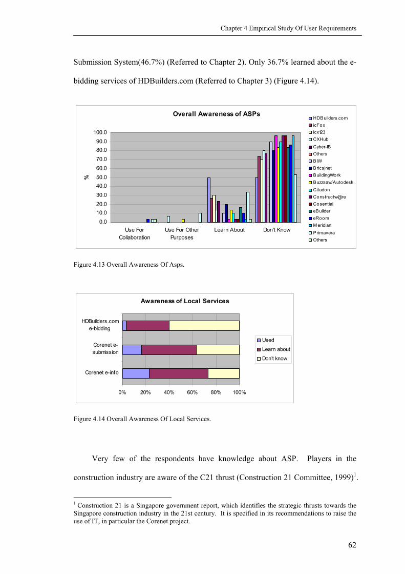
Chapter 4 Empirical Study Of User Requirements
Submission System(46.7%) (Referred to Chapter 2). Only 36.7% learned about the e-
bidding services of HDBuilders.com (Referred to Chapter 3) (Figure 4.14).
Overall Awareness of ASPs
0.010.020.030.040.050.060.070.080.090.0
100.0
Use ForCollaboration
Use For OtherPurposes
Learn About Don't Know
%
HDBuilders.comicFoxicx123CXHub
Cyber-IBOthersBIWBrics|netBuildingWorkBuzzsaw/Autodesk
CitadonConstructw@reCosentialeBuildereRoomM eridian
PrimaveraOthers
Figure 4.13 Overall Awareness Of Asps.
Awareness of Local Services
0% 20% 40% 60% 80% 100%
Corenet e-info
Corenet e-submission
HDBuilders.come-bidding
Used
Learn about
Don’t know
Figure 4.14 Overall Awareness Of Local Services.
Very few of the respondents have knowledge about ASP. Players in the
construction industry are aware of the C21 thrust (Construction 21 Committee, 1999)1.
1 Construction 21 is a Singapore government report, which identifies the strategic thrusts towards the Singapore construction industry in the 21st century. It is specified in its recommendations to raise the use of IT, in particular the Corenet project.
62

Chapter 4 Empirical Study Of User Requirements
To the practitioners in Singapore, it is a matter of time to standardize the business
processes with greater use of IT. They are, in general, aware of the potential power of
the Internet, but are actually waiting for the technology to be commonly accepted by
the industry, like the ubiquity of AutoCAD, before they are willing to put efforts into
implemention in their firms, as one respondent commented:
“Until standardization is in place - at least down to 2 major system
and at least 99% certainty of the ASP's long term survival to protect our
investment and reduce disruption to service, it would be difficult to
convince management to adopt ASPs. I suspect that at this moment, many
CEO's are giving the ok without being fully aware of the risks.”
4.4.3.3 Expected Impacts On Time
By adopting the ASP, the amounts of time on all the 8 listed activities are
expected to be reduced. Some are expected to be shortened greatly, while others
slightly (Figure 4.15).
Among the three physical activities (attending meetings outside your firm,
making site visits, traveling overseas), the time spent on traveling overseas is
expected to reduce mostly (3.8)2. This means that ASP is expected to be most useful
when applied to projects that are across national borders. Time spent on making site
visits is expected to be reduced slightly (3.3). It is unclear whether the respondents
were unaware of the site Web-cam feature of the ASP, or they did not believe that
Web-cam could substitute physical visits.
2 Numbers in parenthesis in this chapter refer to the mean score obtained from the survey.
63

Chapter 4 Empirical Study Of User Requirements
Effect on Time
3.73.3
3.8 3.8 3.54.0 4.3 4.4
0.00.51.01.52.02.53.03.54.04.55.0
Attendingmeetings
outside yourf irm
Making sitevisits
Travellingoverseas
Makingtelephone
calls
Writing email Faxing Searchingfor projectdocuments
Trackingproject
activities
Mea
n Sc
ale
Figure 4.15 Mean Scales Of ASP Effects On Time.
Among the three communication means (making telephone calls, writing email,
and faxing), time on faxing is expected to reduce greatly (4.0). Time on making
telephone call will also reduce much (3.8), but on writing email will only reduce
slightly (3.5). This is because faxing is one of the most popular means of
communication. About 44.2% of construction documents are exchanged through
faxing (Figure 4.9). The document warehouse function of ASP acts similar to the
document exchange by faxing. Therefore, it is possible that ASP will partly substitute
faxing. Email has become a common practice in the Singapore construction industry
(43.3% of construction documents are exchanged via email (Figure 4.9); about 76.4%
of the employees in the respondents’ firms are using email for their work3 ). The
trend is that people will prefer email to phone call when written records are needed.
They will also prefer email to faxing when a softcopy is better than a hardcopy.
Therefore, time on writing email is not expected to reduce much after applying ASP.
Two “soft” activities, searching for project documents (4.3) and tracking project
activities (4.4), are expected to be most efficient with the help of ASP. This is true
3 Calculated from Questions 1.3 and 2.5.
64

Chapter 4 Empirical Study Of User Requirements
because ASP provides well-organized and complete documentation, which eases the
search of information and the tracking of project activities.
4.4.3.4 Evaluation Of As-Is Features
The 7 categories of as-is features are the same as those in Chapter 3. Major
features are also listed in each category, with a screenshot hyperlinked from a
commercial ASP Website (Figure 4.1). The respondents were asked to evaluate each
category, instead of each feature.
Mean Scale of As-is Features
4.0
4.44.4
4.3
4.0
4.4
4.2
3.7
3.8
3.9
4.0
4.1
4.2
4.3
4.4
4.5
General System ApplicationSupport /Document
Management
WorkflowManagement
With Templates
Administration User CentricWorkplace
TeamCommunication
Capability,Stability AndSecurity Of
ASPs
Figure 4.16 Evaluation Of ASP As-Is Features In Terms Of Mean Scales.
Four of the 7 categories were considered very useful: document management
(4.4); workflow management (4.4); administration (4.3); and team communication
(4.4) (Figure 4.16). They are exactly the cornerstones of a collaboration system. The
four categories will be further iterated in the conceptual model in Chapter 5.
65

Chapter 4 Empirical Study Of User Requirements
4.4.3.5 Evaluation Of To-Be Features
Among the 9 listed categories of to-be features identified in Chapter 3, 4 are
considered very useful: time and cost consideration (4.2); integration (4.2); intelligent
search (4.2); and knowledge base (4.1) (Figure 4.17). The improvements of these
features are most likely to have the interests from the common users. They represent
the research directions in the future.
Mean Scale of To-be Features
4.24.2 4.2 4.1
3.73.7
3.8
4.0
3.7
3.4
3.5
3.6
3.7
3.8
3.9
4.0
4.1
4.2
4.3
Time And CostConsideration
Integration Searching ForInformation
Know ledgeBase AndIntelligence
CustomisabilityTo Persons
CustomisabilityTo Projects
Scalability Protection ofknow ledgeproprietary.
Supportingdivision of
responsibilities
Figure 4.17 Evaluation Of ASP To-Be Features In Terms Of Mean Scales.
4.4.3.6 Comments On ASP
Comments on ASP are designed as open questions in which the respondents can
type whatever they want to say. Typical comments are of the benefits, obstacles of
using IT and especially the ASP, and suggestions on ASPs.
4.5 SUMMARY
This chapter discovers the specific requirements of the AEC industry upon IT
and Web-based collaboration. The tendency of IT applications is towards a greater
computerization of the business processes. It is clear from the survey that the most
significant impacts of IT on the construction industry are faster information transfer,
66
Chapter 4 Empirical Study Of User Requirements
reduction in difficulties in project coordination, better communications, and easier and
faster access to common data. Although the Internet has been adopted by most firms
surveyed, a lot of information is still exchanged in its traditional means.
Email is the most common electronic means of exchanging information, but it is
somehow hindered by huge graphic data files that slow down the speed of information
transfer. There is a great need to develop some fast and powerful network systems
that can handle this type of data, and large text documents without sacrificing on the
speed of transfer or downloading time from the Internet so as to encourage more user
participation.
The development of ASP in the Singapore construction industry is still in an
initial stage. Major perceived benefits of adopting ASP include: cost saving,
efficiency, better communications, and well-organized and complete documentation.
Major concerns are high investment costs, risk on data security, greater know-how
required from staff, and IT infrastructure constraint. By adopting the ASP, the amount
of time spent on various project management activities is expected to be less.
The result of general awareness of ASP is a bit disappointing. Due to a low
awareness of ASP and Internet-based services, the evaluations of ASP features are
more of expectations than of facts.
Some ASP as-is features that were regarded very useful were identified:
document management; workflow management; administration; and team
communication. The categories of ASP to-be features that were considered very
useful include: time and cost consideration; integration; intelligent search; and
knowledge base.
67

Chapter 4 Empirical Study Of User Requirements
68
With the advancements made, the remaining obstacle is a mind set change of the
players in adopting new technology for their work in the construction industry.

CHAPTER 5 CONCEPTUAL MODEL DEVELOPMENT
5.1 INTRODUCTION
The last chapter identified 4 useful as-is features and 4 to-be ones of ASPs
through a Web-based survey. This chapter incorporates the 4 as-is features and 1 to-
be feature, integration through data markup, into the conceptual model. Only 1 to-be
feature has been included due to research scope and time limit, which is both the
contribution and the limitation of the study.
This chapter first introduced the terminology of the Unified Modeling Languang
(UML), including symbols, structure of a UML model, and modeling strategies. Next,
the main use case of the conceptual model is described, followed by further
descriptions of some elements that are most related to Data Markup Integration (DMI).
A detailed documentation of the conceptual model is included in Appendix III.
5.2 THE UML MODELING METHOD
UML is a language for systems engineering (OMG, 2000). It is chosen for the
development of the conceptual model because it is rapidly established as a de facto
international standard for object-oriented modeling. There are many CASE (Computer
Aided Software Engineering) tool that supports UML, among which is Rational Rose
that has been applied by this study. UML provides a series of diagrams (Hannus and
Kazi, 2000), such as use case diagram, class diagram, object diagram, sequence
diagram, collaboration diagram, statechart diagram, activity diagram, component
69

Chapter 5 Conceptual Model Development
diagram, deployment diagram, and package diagram. The conceptual model in this
study includes mainly the following diagrams:
• Use Case diagram that describes functionality provided by a system to
external integrators (e.g., Figure 5.5);
• Activity diagram that describes the behavior in response to internal processing
(e.g., Figure 5.9);
• Collaboration diagram that describes the flow of messages, focusing upon the
relationships between the objects (e.g., Figure 6.3).
5.2.1 The UML Modeling Approaches
There are two UML approaches of conceptual modeling: the use case driven
approach, and the class driven approach. The use case driven approach describes the
system from the external user’s point of view and is most suitable for domain
knowledge analysis. The class driven approach describes from the system designer’s
point of view and is for technical development at a later stage (Schneider, & Winters,
2001). This study applies the use case driven approach, since conceptual modeling is
at an early stage of the development cycle. Use case driven approach is emphasized,
if not recommended, by UML (Maciaszek, 2001).
The graphical model of use cases is supplemented with narrative descriptions
and with sequence or collaboration diagrams for individual use cases. These
additional descriptions and diagrams define steps and objects needed for each use case
to occur.
70

Chapter 5 Conceptual Model Development
The conceptual model of this study mainly involves four elements: actor, use
case, activity, and package.
An actor is a group of people or a system that is outside of the system and
interacts with the system. Each actor defines a particular role. To interact with the
system, an actor must initiate at least one use case. An actor is represented by a stick
figure (Figure 5.1).
A use case describes a specific way of using a system. The identified use cases
describe the functionality performed by the system as a result of a request from an
actor. Use cases provide a way to capture the requirements about the system,
communicate with the end-users and domain experts, and test the system (Bjork,
Huovila, and Hult, 1993). Use cases are the main representative modeling elements in
the study. A use case is represented by a labeled oval (Figure 5.1). Extend is a
relationship between two use cases. Where A extends B, it means A describes more
specific behavior and B the general version of that behavior.
User
(from Use Case View)
Manage Change
Manage RFI
Manage VO
<<extend>>
Figure 5.1 Actor And Use Cases.
An activity diagram is used to graphically represent the flow of events of a use
case. It is a lower level representation for detailed description of the use case. An
71

Chapter 5 Conceptual Model Development
activity is represented by a round-corner rectangle (Figure 5.2). An activity diagram
depicts a start state, activities that the system performs, decisions that determine
which activity is performed next, and one or more end points.
Log In
Display Log In Page
Get User Name And Password
Verify User Name And Password
Display Error Message
Time Out
Display What's New
Invalid
OK
Figure 5.2 Activity Diagram.
Packages serve to partition the model. They are the clusters of highly related
modeling elements, such as use cases and classes. They are used to model higher
level representation. A package is represented by a rectangle with a small rectangle
attached on the top left (Figure 5.3).
Team Communication
Manage Document
Manage Workflow
Log In
Figure 5.3 Packages.
For complete explanation of the UML terminology and symbols, please refer
to Maciaszek (2001).
72
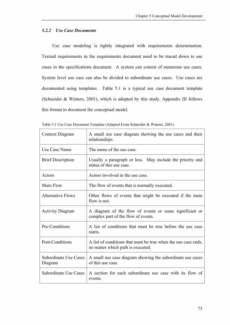
Chapter 5 Conceptual Model Development
5.2.2 Use Case Documents
Use case modeling is tightly integrated with requirements determination.
Textual requirements in the requirements document need to be traced down to use
cases in the specifications document. A system can consist of numerous use cases.
System level use case can also be divided to subordinate use cases. Use cases are
documented using templates. Table 5.1 is a typical use case document template
(Schneider & Winters, 2001), which is adopted by this study. Appendix III follows
this format to document the conceptual model.
Table 5.1 Use Case Document Template (Adapted From Schneider & Winters, 2001).
Context Diagram A small use case diagram showing the use cases and their relationships.
Use Case Name The name of the use case.
Brief Description Usually a paragraph or less. May include the priority and status of this use case.
Actors Actors involved in the use case.
Main Flow The flow of events that is normally executed.
Alternative Flows Other flows of events that might be executed if the main flow is not.
Activity Diagram A diagram of the flow of events or some significant or complex part of the flow of events.
Pre-Conditions A list of conditions that must be true before the use case starts.
Post-Conditions A list of conditions that must be true when the use case ends, no matter which path is executed.
Subordinate Use Cases Diagram
A small use case diagram showing the subordinate use cases of this use case.
Subordinate Use Cases A section for each subordinate use case with its flow of events.
73

Chapter 5 Conceptual Model Development
The use case document evolved with the development progress. In the early
stage, only a brief description is written. Other parts are written gradually and
iteratively. A complete document emerges at the end of the requirements
specification phase (Maciaszek, 2001).
5.3 MAJOR ACTORS
Actors can be regarded as classes, therefore, they have attributes and operations.
The actors identified in this study are: ASP, CIO, and User. ASP is the platform and
service provider.
CIO (Chief Information Officer) is the platform administrator. Its duty is to
manage the project Web throughout the whole process of Web site utilization. Since
the information manager controls the entire project information, it is suggested that
this person shall come from a third party of the project, such as a staff of the ASP, so
as to remain unbiased to all parties of the project. In practice, the administrator could
be the client, the project manager, the main contractor, or any main player of the
project who is in charge of the administration of project information. User is the one
who uses the ASP services.
User is a generic class, which is inherited by Client, Project Manager,
Designer, and Contractor. Designer is inherited by Architect and
Engineer. Contractor is inherited by Main Contractor and Sub-
contractor (Figure 5.4).
Inherit is a relationship among classes, which is represented by a hollow arrow
pointing from the son class towards the father class. Different son classes inherit the
74

Chapter 5 Conceptual Model Development
same generic attributes of their father class while having specific attributes distinct
from each other.
According to the roles of the users, their rights to access certain information is
different. For example, the sub-contractor is not supposed to know the contract
between the client and the main contractor.
User
Architect Engineer
Project Manager
Main Contractor Sub-contractor
ClientContractor
Actors
Designer
Figure 5.4 User Inheritances.
5.4 THE MAIN USE CASE
Chapter 4 identifies the four most useful categories of features: document
management, workflow management, team communication, and administrate project.
They are incorporated in the conceptual model as four packages. In addition, My
Project Place, the use-centric workplace, is also included as a package. DMI is
incorporated all over the model and not as a specific package. The next few
paragraphs discusses the main use case (Figure 5.5) and how the components inside
are relevant to DMI.
75

Chapter 5 Conceptual Model Development
5.4.1 Setup Project Service
The use case Setup Project Service is to set up the infrastructure for
the project, which initiates the use of a project Website.
Main Use Case
Project Manager
Setup Project Service ASPSetup Project Website
Log In
CIO
User
Setup User
Manage Document
Manage Workflow
Team Communication
My Project Place
Administrate Project
Figure 5.5 Main Use Case.
5.4.2 Setup Project Website
The use case Setup Project Website is to set up the framework for the
Website (Figure 5.6). It defines the standardized templates to manage document and
workflow (Define Document Directory, Define Document
Templates, Define Workflow Templates, etc). It also defines the business
logics for the system to execute (Define Business Logic, Assign Group
Permission Right, Define User Interface, etc). A template determines
the standard and structure of a portfolio. When the user creates a new file, the system
obtains certain data from the template. Using a template can quickly create project
76

Chapter 5 Conceptual Model Development
wide standards and reduce time-consuming data entry. A standardized template based
on XML (eXtensible Markup Languang, will be discussed in Section 6.4), such as a
form for RFI, defines the meaning of each input field, which can be easily interpreted
by the system. For example, the inputs in the field of “From” are saved in XML
format as:
<From> <ActorSelect>
<Person>YS Liu</Person> <Organization>Position of staircase handrail</Organization>
</ActorSelect> </From>
Setup Project Website
Define Document Templates
Define Workflow Templates
Define User Interface
Assign Group Permission Right
Define Document Directory
Define Business Logic
Figure 5.6 Setup Project Website.
5.4.3 Setup User
The use case Setup User is to setup the profile of the users that can access
the project Web and their rights to access information. It is possible to keep sensitive
information from being reached by restricting some users’ access rights.
77

Chapter 5 Conceptual Model Development
5.4.4 Log In
The use case Log In is to verify the user. It also acts as the access to
personalized Headline page and all functional packages (Figure 5.2).
5.4.5 Package Manage Document
The package Manage Document should be able to manage various types of
file, such as drawings, schedules, cost, customized documents, to name a few (Figure
5.7). It should also be able to handle the files by allowing uploading, viewing,
searching, commenting, and printing (Figure 5.8). There are three features that are
related to DMI: Upload file, Search file and Search topic.
Manage Document
Manage Drawing
Manage Schedule
Manage Cost
Manage Document Inheritance
Manage User Defined Document
Manage Document
Download File
Comment File
Print File
Track File
View File
<<extend>>
<<extend>>
<<extend>>
<<extend>>Search File
Search Topic
Upload File
User
(from Use Case View)
Figure 5.7 Manage Document Inheritance. Figure 5.8 Manage Document.
Upload file is for file uploading. Meta-data of the file, such as author,
date, and description, is required to key in by the document author, so as to ease the
search of the file on the project Website. With meta-data, the file can be searched by
78

Chapter 5 Conceptual Model Development
various criteria. The meta-data is saved in XML format. The process of uploading a
file is shown in Figure 5.9.
Search file is for file searching (Figure 5.10). With meta-data, the system
can neatly present various search result based on the user’s search criteria other than
full text, such as by description, or by category, e.g., draft drawing, shop-drawing. It
enhances the quality of searching by presenting the most targeted file to the user.
Upload File
Display Upload Page
Get File Location
Verify File Format
Verify File Name
Prompt To Upload Valid Format File
Assign Version No.
Display Default Meta Data
File Name Changed
Upload File
Save Meta Data
Inform Relevent User
Update Topic Index
Assign File ID
Update File Index
File Name Not Change
Invalid Format
Valid Format
Figure 5.9 Upload File.
Search File
Display File Search Page
Get Search Criteria
Search File Index
Display Search Result
Figure 5.10 Search File.
79

Chapter 5 Conceptual Model Development
Search topic is for integrated presentation (Figure 5.11). It is the most
important use case to demonstrate how XML enabled collaboration system differs
from others. It searches related information in the project Website, and integrates the
search result into a single webpage. This means user can extract useful pieces of
information from all sources in the project Website and put them together for analysis
and decision making. It shortens the time on information searching and organizing,
allows user to concentrate on information analyzing and decision making.
The user can search a topic based on various criteria marked up by XML, such
as “handrail” as the type in a quotation, or comments by a specific author in the series
of an RFI. User can browse through the search result and marks useful items. The
marked information can be saved for future use. XML compatible information can
be copied and pasted to the Saved Items. XML incompatible information can be
viewed in specialized viewers or plug-ins (Refer to Section 6.4.4 for discussion on
XML compatibility). When the user gets enough information, he or she can review
the saved items, indicates how the information should be displayed, which should be
saved for permanent use, and which should be linked to the Workflow
Management for short-term use. Chapter 6 will explain this concept in an example
of Request For Information case.
80

Chapter 5 Conceptual Model Development
Display Topic Search Page
Display Itegrated Information
Get Display Choice
Display Search Result
Search Topic Index
Get Search Criteria
Search Topic
Browse Search Result
Mark Useful Information
Save Marked Information
Save Search Result
More Information Needed Get Enough Information
Figure 5.11 Search Topic.
5.4.6 Package Manage Workflow
In the package Workflow Management (Figure 5.12), standardized
workflow is realized through information templates and automatic execution of
business rules. A workflow consists of several tasks. Tasks are small jobs that the
project manager assigns to the project users, such as responding to a Request For
Information (RFI), approving a Variation Order (VO), etc. When one task finishes,
the system automatically brings the next. When all tasks are finished, the workflow
ends. The benefit of automatic workflow management is to speed up the
communication and confirmation on decisions.
The use case Manage My Work Package provides various tools to facilitate each
user to manage workflows that are related to him or her. In such a way, the
81

Chapter 5 Conceptual Model Development
information resides in different documents can be managed according to a user’s need,
and can be integrated to handle workflows.
Manage Workflow
Manage Change
Manage Purchase Order
Manage Meeting Minute
Manage TransmittalsUser
(from Use Case View)
Manage Field Report
Manage Material
Manage My Work Package
Manage My Task
(from My Project Place)
<<extend>>
Contractor
(from Use Case View)Mange Sub-contract
Figure 5.12 Package Management Workflow.
In Chapter 6 an RFI case is prototyped to validate the conceptual model. The
general process of RFI is discussed here. A user, be it the designer, project manager,
or contractor, can manage the RFI by initiate it or respond to it. An RFI could be
extended to a Variation Order should the change be approved (Figure 5.13).
User
(from Use Case View)
Manage Change
Manage RFI
Manage VO
<<extend>>
Figure 5.13 Manage Change.
82

Chapter 5 Conceptual Model Development
Figure 5.14 shows the workflow of an RFI. The use case begins when the User
initiates a new RFI. The system displays the webpage for RFI input.
Create RFI
Submite RFI
Reply RFI
View RFI
Redirect RFIRequire Clarification
Close RFI
Workflow of RFI
Able to Answer
Unable to AnswerQuestion Not Clear
Satisfied With ResponseNot Satisfied With Response
Figure 5.14 Workflow Of RFI.
When the User finishes all input, the system saves the RFI to its database. If
the initiator indicates a party to answer the RFI, the system sends a notification to that
party. If not, the system sends the notification to the Project Manager, so that
he or she will assign the task to a responsible party.
The responsible User receives the notification, views the RFI, and answers the
RFI. The system saves the answer, notifies the initiator and the Project
Manager. If the initiator is satisfied with the answer, he or she closes the RFI and
the workflow ends. If further clarification is needed, the responsible User adds his
or her comments and redirects the RFI back to the initiator for clarification.
83

Chapter 5 Conceptual Model Development
If the responsible User is unable to answer the RFI, he or she adds new
comments, redirects the RFI to a User who can answer the RFI. The new
responsible party goes through viewing and replying RFI or redirecting it to another
responsible party, until one party answers the question to the satisfaction of the
initiator.
5.4.7 Package Team Communication
While Manage Workflow is a formal way to manage collaboration, Team
Communication can act as less formal discussion (Figure 5.15). The features of
BBS (Bulletin Board System), instance messaging, online conference, and email
provide speedy and traceable means to record informal discussions, which can be
formally documented into the workflow management, or serve for decision-making.
Team communication thus simplifies the processes of workflow. Inputs in team
communication are also saved in XML format, and therefore, are traceable by using
Search Topic.
Manage Email
Instance Messaging
BBS
Online Conference
View Project CalendarView Contact
User
(from Use Case View)
Team Communication
Figure 5.15 Team Communication.
84

Chapter 5 Conceptual Model Development
5.4.8 Package My Project Place
My Project Place is a personalized work station (Figure 5.16). Every user
can view his or her own tasks, and job related information. This simplifies the users’
environment, allows the user to concentrate on relevant information. It is possible
with XML technology because the system tailors the information to suit the users’
need.
5.4.9 Administrate Project
In a workflow, each task automatically starts after its precedent finishes, given
that the tasks are assigned to the responsible parties by the Project Manager. This is
done through the package of Administrate Project (Figure 5.17). The preset
business rules define the framework of who is responsible to do what by the deadline
of when, and what if the task is not finished on time. The project manager only needs
to fill in the specific items for each collaborative workflow.
My Project Place
View What's New
Manage My Profile
View Webcam
Manage Subscription
User
(from Use Case View)
Figure 5.16 My Project Place.
85

Chapter 5 Conceptual Model Development
86
Maintain User
Manage User
Manage File
Manage Activity
Project Manager
(from Use Case View)
Setup User
(from Use Case View)
CIO
(from Use Case View)
Administrate Project
Figure 5.17 Administrate Project.
5.5 SUMMARY
This chapter describes the conceptual model for Web-based construction project
management. Use cases and packages that are most relevant to DMI are highlighted,
which will be further discussed in Chapter 6. A complete conceptual model is
documented in Appendix III.

CHAPTER 6 PROTOTYPING OF REQUEST FOR
INFORMATION
6.1 INTRODUCTION
The last chapter describes the conceptual model from the system viewpoint.
This chapter prototypes the Request For Information (RFI) to verify its usefulness of
the Data Markup Integration (DMI) system. Prototyping the RFI case also
demonstrates technical feasibility of implementing the DMI conceptual model using
XML technology. There are two reasons for choosing RFI for prototyping. Firstly, it
is a common and typical document in project collaboration. Secondly, it is scalable,
each of which can involve from few to many parties, which is typical for Web-based
collaboration (Leung, Chan, & Issa, 2003).
6.2 THE REQUEST FOR INFORMATION SCENARIO
The RFI scenario presented here is a real case of an MRT (Mess Rapid Transit)
project in Singapore. As instructed by the information provider, names of the
companies and persons are replaced by fictitious ones.
In this design-and-build project, the Main Contractor (company MC) acts as the
project manager. The Architect (company AR) serves for MC. The Client (company
CL) is a government agency in charge of national MRT projects. CL supervises the
project, dealing with major decision making, and authorizing changes to the project
work. In company MC, YS Liu is the Project Manager (PM), and M Ang is the
87

Chapter 6 Prototyping Of Request For Information
Quantity Surveyor (QS). K Foo is the Qualified Person (QP) and chief architect in
AR. In company CL, C Tan is the PM, and R Chee is the QS (Table 6.1).
Table 6.1 Person, Role And Company
Name of Person Role of Person Name of Company
Role of Company
YS Liu PM MC Main Contractor M Ang QS MC Main Contractor K Foo QP AR Architect C Tan PM CL Client R Chee QS CL Client Note: PM = Project Manager; QS = Quantity Surveyor; QP = Qualified Person.
The RFI was about the location and material of a staircase handrail. The
handrail could not be built as shown in the original drawing, due to position conflict
with the steel column footings (Figure 6.1). Since steel type was not specified in the
original drawing, MC also wanted to clarify the type of stainless steel to be used
(Type 316 or Type 304).
Figure 6.1 Original Detail Drawings Of The Parapet.
The actual process was paper-based (Figure 6.3), in which information was
exchanged via faxing. This process is simulated in the DMI environment (Figure 6.4).
88
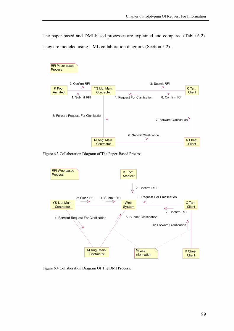
Chapter 6 Prototyping Of Request For Information
The paper-based and DMI-based processes are explained and compared (Table 6.2).
They are modeled using UML collaboration diagrams (Section 5.2).
YS Liu: Main Contractor
K Foo: Architect
C Tan: Client
M Ang: Main Contractor
R Chee: Client
RFI Paper-based Process
1: Submit RFI
2: Confirm RFI 3: Submit RFI
4: Request For Clarification 8: Comfirm RFI
5: Forward Request For Clarification
6: Submit Clarification
7: Forward Clarification
Figure 6.3 Collaboration Diagram of The Paper-Based Process.
YS Liu: Main Contractor
Web System
K Foo: Archiect
C Tan: Client
M Ang: Main Contractor
R Chee: Client
Private Information
RFI Web-based Process
1: Submit RFI8: Close RFI
4: Forward Request For Clarification
2: Confirm RFI
3: Request For Clarification
7: Confirm RFI5: Submit Clarification
6: Forward Clarification
Figure 6.4 Collaboration Diagram Of The DMI Process.
89

Table 6.2 Comparison Of Paper-Based And DMI Processes.
Paper-Based Process DMI Process 1 YS Liu created an RFI and proposed his
own solutions (Table 6.3). Drawing of the proposed solution was attached with the RFI and faxed to K Foo (Figure 6.1, Figure 6.4).
YS Liu logs in to the system, creates and subma new RFI (Figure 6.5). Drawing of the proposolution is uploaded to the Web site. The Rcontains a link to that file. The system notifies K Fand C Tan concurrently.
2 K Foo received the fax. He manually compared the proposed drawings with the original drawing to find out the cause of chang.
K Foo responded:
Question 1: Proposed solution is not ideal; Pedestrian might hit stump, better hack the kerb. Question 2: T304 is used in general occasions, while T316 in high-cautery or high-humidification situations. T304 is acceptable to designer.
Later he called YS Liu and learned that the kerb could not be hacked. He waited till the weekly site meeting, investigated the site situation, and added a third comment after question 2:
You have confirmed kerb is structural and can not be hacked. Build it as proposed. K Foo faxed the RFI back to YS Liu.
K Foo views the RFI online. He reviews drawings by simply clicking the URL that links to files. The two drawings are shown on the screen him to compare (Figure 6.6).
K Foo can use BBS to create a discussion whether the kerb can be hacked. He can also requYS Liu to send site photos to him via Web-CaWhen he needs to add a new comment, he can adin the answer to question 1.
K Foo responds:
Question 1: Proposed solution is not ideal; Pedestrian might stump, better hack the kerb. You have confirmed kerb is structural and can not bhacked. Build it as proposed. Question 2: T304 is used in general occasions, while T316 in hicautery or high-humidification situations. T304acceptable to designer.
K Foo submits his comments. The systinforms YS Liu and C Tan that K Foo’s new commis available.
3 YS Liu faxed the RFI to C Tan for comment.
-
Chapter 6 Prototyping Of Request For Information
Comparison
its sed FI oo
In the DMI process, the RFI can be responded concurrently by more than one party, so as to shorten the total responding time.
the the for
on est m.
d it
hit
e
gh- is
em ent
In the DMI process, references are available by simply clicking at the URL that links to the file. This shortens the time to manually look for the references.
In the DMI process, the architect can make decisions faster because Web-Camera reduces his physical visits to the site.
In the paper-based process, additional information is recorded according to chronological order, i.e., the third comment was added after the second comment. While in the DMI process, information can be recorded according to logical order, i.e., the third comment is an answer to question 1, so it is added between the first and the second comments.
The DMI system automatically informs the relevant parties to view the information.
90

Chapter 6 Prototyping Of Request For Information
Table 6.2 Comparison Of Paper-Based And DMI Processes (Continued).
Paper-Based Process DMI Process Comparison 4 C Tan reviewed the RFI and requested a
quotation for the two materials. He called K Foo to discuss the RFI. K Foo told him there were no better solutions for Question 1, and no regulation restriction for the type of steel to be used. C Tan then commented:
Question 1: No comments. Agree with AR. Question 2: Please provide quotation.
The RFI was faxed back to YS Liu.
C Tan reviews the RFI and requests a quotation for the two materials. He can also use telephone, BBS, instant messaging, email, or other communication means to discuss with K Foo or YS Liu before he comments. When C Tan submits his comment, the system notisfies both YS Liu and K Foo.
Informal discussions are important to the final decision making. In a paper-based process, there are limited means, such as telephone and face-to-face discussion, in which information is hard to be recorded. In the DMI process, informal discussions can be carried out via various means and recorded as part of the whole project information. For example, discussions on BBS have been proved to be efficient and traceable.
5 YS Liu forwarded the request to M Ang, the QS of MC, instructing her to provide a QFC to the QS of CL.
YS Liu adds his comment and forwards the RFI to M Ang, the QS of MC.
In the DMI process, YS Liu does not need to repeat the question to M Ang, because Ang can review the question and drawings to find out where the handrail locates.
6 M Ang prepared a separated Quotation For Change (QFC) for R Chee, the QS of CL, to approve (Table 6.5). In order to provide the QFC she manually looked for the handrail item in the original quotation (Table 6.4).
The QFC was faxed to R Chee. Other employees in CL might have viewed the file before it reached R Chee.
M Ang creates a new Quotation For Change (QFC) and submits it to the system. In order to provide the QFC she instructs the system to find the original quotation for her, copies the handrail item, and pastes it to the new QFC.
The QFC is embedded in M Ang’s Response to RFI (Figure 6.7). The system notifies R Chee, the QS of CL to view it. M Ang can set the QFC as private, which means only she and R Chee, the explicit receiver, can view the content.
The DMI process provides the convenience to copy and paste information from one file to another. This reduces data re-input, which in turn reduces the chances of errors.
In the paper-based process, the RFI and QFC are separated. While in the DMI process, they are integrated. Both the information provider and receiver enjoy the convenience of reviewing the whole set of information, instead of integrating the information from fragmented documents.
In the DMI process, sensitive information can be set as private, which means only the information provider and explicit receivers can view the content.
91

Chapter 6 Prototyping Of Request For Information
Table 6.2 Comparison Of Paper-Based And DMI Processes (Continued).
Paper-Based Process DMI Process Comparison 7 R Chee reviewed the QFC, looked for
relevant items in the original quotation, compared them and submitted a cost impact report to C Tan.
R Chee compares the items in QFC with the original quotation by clicking the URL that links to the file. He submits a cost impact report to C Tan, recommending him not to change the material.
In the paper-based process, both M Ang and R Chee search the handrail item in the original quotation. This repeat is a waste of time. In the DMI process, R Chee can easily refer to the original quotation because the system saves the source of information from M Ang’s activity.
8 C Tan chose Type 316, and signed on the quotation page. The quotation page was faxed back to YS Liu.
C Tan chooses Type 316 by responding to the RFI. A notification is sent to YS Liu.
In the paper-based process, since RFI and QFC are separated, C Tan comments on the decision in the QFC, instead of the RFI. This can easily cause argument due to information lost. In the DMI process, the QFC and other references are either link to or embedded in the RFI. All comments are integrated in the RFI log.
9 YS Liu added his confirmation note to the RFI:
Question 1: AR confirms if stump can not be hacked, handrail is to offset to 200mm from parapet wall. Question 2: CL confirms using Type 316 S.S. for the railing.
YS Liu circulated the last RFI to each party for documentation, including C Tan, R Chee, K Foo, M Ang and himself (Table 6.3).
YS Liu adds his summary note and closes the RFI. Notification is automatically sent to every party, including C Tan, R Chee, K Foo, M Ang, and YS Liu himself. They can review the RFI and related comments in an integrated webpage called Summary Of Request For Information (Figure 6.8).
In the paper-based process, every fax is a new result to the RFI. In order to see the whole process, the parties have to document every result. Information receivers can not access the information until it is disseminated by the provider. While in the DMI process, the system documents both the process and the result for every party to review. Even informal discussions can be linked to the summary, if they are regarded as important. Information is always available to both the provider and the receivers.
92

Chapter 6 Prototyping Of Request For Information
In the paper-based process, MC proposed his questions and recommendations of
the RFI. The RFI was faxed to AR for clarification, then to CL for comment. They
used phone calls and site meetings to discuss this RFI, before they wrote down their
comments and faxed back to MC. MC marked his summary note and faxed back to
each party, then he installed the handrail.
The RFI was about a simple question. The information was circulated between
three parties and five persons. However, the RFI had been faxed for at least 5 times,
each of which new comments were added. At last, the handwritings on the RFI were
blurred and difficult to distinct. Confirmations on the two questions were made
separately (AR confirmed the position of handrail on RFI, while CL confirmed the
material on QFC), if not for MC’s the summary note. This could have easily caused
arguments since CL’s confirmation was not documented on the RFI.
Figure 6.4 Proposed Detail Drawings Of The Parapet.
93

Chapter 6 Prototyping Of Request For Information
Table 6.3 Request For Information Form.
REQUEST FOR INFORMATION (RFI) Page 1 of 2
To:
K Foo (AR)
MC RFI No:
RFI/FNCAS/1522
Date: 18 / 10 / 2001
S/C Company:
Location Of Works On Site: (Area, Gridlines, Level Etc) Entrance 1 of GB Staircase Raised by (Name):
S/C RFI Reference:
Subject: Handrail position and material at GL (RA) side parapet Date issued to MC:
Query: The original design of handrail along GL(RA) is 80mm away from the parapet wall. Since the position does not coincide with the steel column footing at this position, the handrail should be at least 200 mm away from the wall. Please confirm the distance. Handrail material is not specified in the original design. Please confirm whether Type 316 or Type 304 is to use. Drawings/Specifications Reference: C709 Originator (Name & Signature): Y.S. Liu
Answer required by: 20 / 10 / 2001
Response: Question 1: Proposed solution is not ideal; Pedestrian might hit stump, better hack the kerb. Question 2: T304 is used in general occasions, while T316 in high-cautery or high-humidification situations. T304 is acceptable to designer. K Foo You have confirmed kerb is structural and can not be hacked. Build it as proposed. K Foo 24/10/2001 Question 1: No comments, agree with AR. Question 2: Please provide quotation. C Tan 28/10/2001 Question 1: AR confirms if stump can not be hacked, handrail is to offset to 200mm from parapet. Question 2: Client confirms using Type 316 S.S. for the railing. Y.S. Liu 30/10/2001
Final Circulation (Doc. Controller)
Copy
Action
R P G P R A 1 L C 1 Major Change
Minor Change
X
To be RE Endorsed
By (Name): ____________ Signature: _______________ Date: __ / __ / ____
94

Chapter 6 Prototyping Of Request For Information
Table 6.4 Part Of The Original Quotation.
Quotation S/n
Description Qty Unit Rate Amount
15.0 RAILING
15.1 Fabricate, supply and install galvanized mild steel railing to P.P. Complex comprising top and bottom rail, decorative balusters, bars, anchor bolt and all welded together hoisted and fixed in position including filling smooth junction.
1 Item 7000.00 7000.00
15.2 Fabricate, supply and install type 316 stainless steel railing to planter boxes and foot stomping area comprising top and bottom rails, balusters, bar, steel posts, anchor bolt and all welded together hoisted and fixed in position including filling smooth junction.
1 Item 14000.00
14000.00
16.0 DECK FINISHES
16.1 Lay Flamed granite and including supply and install cement and sand (1:3) bedding mortar and pointing in colored cement to footpath.
1 Item 23000 23000
16.2 Lay pebble wash including supply and install cement and sand (1:3) bedding mortar and pointing in colored cement to deck finishes
1 Item 9000 9000
Table 6.5 Quotation For Change Form.
Quotation For Change MRT Project 28/10/2001
Description Qty Unit Rate Amount (S$)
Deduction Fabricate, supply and install type 316 stainless steel railing to planter boxes and foot stomping area comprising top and bottom rails, balusters, bar, steel posts, anchor bolt and all welded together hoisted and fixed in position including filling smooth junction.
1 Item 14000.00
14000.00
Addition Fabricate, supply and install type 304 stainless steel railing to planter boxes and foot stomping area comprising top and bottom rails, balusters, bar, steel posts, anchor bolt and all welded together hoisted and fixed in position including filling smooth junction.
1 Item 8500.00 8500.00
Comment Please use T316. C Tan 30/10/2001 By (Name) __________ signature ___________ Date __ / __ / ____
95

Chapter 6 Prototyping Of Request For Information
To simulate the paper-based process, activities in the DMI process are
intentionally designed to be close to the actual ones. To simplify the process, the
activity of system automatic notification is abridged from the collaboration diagram
(Figure 6.4).
The RFI and related responses are neatly documented in chronological order.
References are easy to find since they either are embedded in the RFI or can be access
by clicking at the hyperlinks. All responses are documented in the RFI to reduce
arguments stemmed from ambiguity. Responsible parties can concurrently response to
the RFI, instead of one after another. The process can be tracked at anytime. This not
only reduces total response time, but also minimizes unnecessary delay of the whole
process due to one party’s temporary absence.
To summarize the benefits of the DMI process in the RFI scenario, it provides
the convenience of ready, complete and integrated information in a timely manner,
which helps the users to make decisions faster and more accurately, so that the
downstream parties can take actions faster. It also helps to keep track of the
collaboration, reduce data re-input, and minimize errors. The key benefit of the DMI
process is the availability of information integration, in the manner of extracting useful
information from referred files and integrating to the original RFI for decision making.
According to the theory of process redesign (Hammer & Champy, 1993)
discussed in Chapter 2, the ultimate benefits of IT applications are achieved through
organizational process re-design, instead of tactical and operational improvements. In
other words, an analysis on how to apply the DMI system as a whole to simplify a
process is more meaningful than to break it down and simulate the paper-based process.
Nevertheless, comparison and analysis on the RFI processes demonstrate some general
96

Chapter 6 Prototyping Of Request For Information
characteristics of the DMI system (Leung, Chan, & Issa, 2003). Later in Section 6.4.5,
analysis of the RFI case will be extended to the overall conceptual architecture of
information exchange (Figure 6.16).
Figure 6.5 RFI Created By YS Liu.
97

Chapter 6 Prototyping Of Request For Information
Figure 6.5 RFI Created By YS Liu (Continue).
98
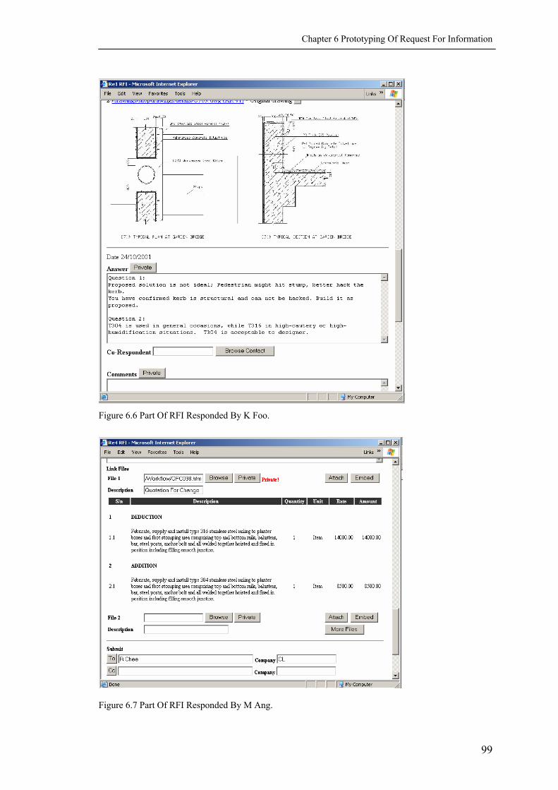
Chapter 6 Prototyping Of Request For Information
Figure 6.6 Part Of RFI Responded By K Foo.
Figure 6.7 Part Of RFI Responded By M Ang.
99

Chapter 6 Prototyping Of Request For Information
Figure 6.8 Summary Of RFI.
100

Chapter 6 Prototyping Of Request For Information
Figure 6.8 Summary Of RFI (Continued).
101

Chapter 6 Prototyping Of Request For Information
6.3 USE CASES INVOLVED
This section will analyze how the functional units in the DMI system collaborate
among one another to serve information integration. In Chapter 5, the conceptual
model of the DMI system was presented. The system consists of 5 packages and some
top level use cases. Each use case may consist of several subordinate use cases
(Appendix III). Table 6.6 summarizes the use cases involved in the DMI RFI process,
as well as the information they provide.
Since internal collaboration of the DMI system is out of the scope of requirement
analysis, it is not discussed here. To complete a workflow, such as a RFI, it requires
many functional units of the system to interoperate, which should be carefully
considered in the system design stage. The key for information integration is the
assistant tools provided by the system to finish the task. On top of the Response To
Request For Information (ReRFI) page are menus of Search Topic, Search File,
Hightlight, etc. These functional units belong to different packages but have been put
together to assist users accomplishing their jobs. By invoking Search Topic, user looks
for relevant references, extracts useful information, and uses the information to create
new information for the current task. In other words, the system integrates relevant
functional units as assistant tools according to the task, i.e., ReRFI. By invoking these
tools, a user can search for relevant information, creates new information, and finish
the current task.
102

Chapter 6 Prototyping Of Request For Information
Table 6.6 Use Cases Involved In The DMI RFI Process.
Package Use Case Information Description
1 Setup User Information access rights
Controlling information access rights. For example, K Foo has no access right to the Quotation and the QFC.
2 Login Login page Verifying user; retrieving user profile, displaying user specific Headline page.
3 My Project Place View What’s New
What’s New Providing summary of new arrival items.
4 My Project Place View My Task
Tasks Displaying tasks that user is responsible for.
5 Manage Workflow
Manage Change
Summary of Changes
Providing summary of change items.
6 Manage Workflow
Manage RFI (Response To) RFI
Providing RFI and Response to RFI forms, and the summary page when the RFI is closed.
7 Manage Document
Upload File C709.dwg Uploading the drawing for proposed solution.
8 Manage Document
View File
C709.dwg (MC v1)
C709.dwg (AR v1)
Displaying files, either embedding the file to the RFI, or opening it in a new window, depending on how the link provider wants it to display.
9 Manage Document
Search Topic
Search results of handrail, integrated QFC
Providing search results of handrail, integrating the selected item (15.2) to the new QFC.
10 Manage Document
Manage Cost
Quotation, QFC
Repositing the original Quotation and the QFC.
11 Team Communication
BBS BBS Recording informal discussions of whether the kerb can be hacked or not.
12 Administrate Project
Manage Activity
Activity log Assigning tasks to the responsible parties.
6.4 EXTENSIBLE MARKUP LANGUAGE
In the previous sections the DMI system was described via demonstration of user
interfaces. This section will discuss system architecture. The key is XML technology.
XML acts as the neutral file exchange format in the system. There are many tools to
103

Chapter 6 Prototyping Of Request For Information
develop XML. The interface prototype is developed using XMLspy (XMLspy, 2002),
which is also applied on the development of ifcXML by IAI (Liebich, 2001; Liebich,
& Adachi, 2000). Since XML is platform independent, the system can be developed
on any platform that supports the development tools, though in this study it was
developed on Windows ME on a Fujitsu notebook with Pentium III 900 CPU and 256
RAM.
6.4.1 XML In The Scenario
Figure 6.9 shows the document exchange architecture of the Web-based RFI
scenario. The webpages discussed above are dynamic HTML (HyperText Markup
Language) transformed from the document XML by the document XSLT (eXtensible
Stylesheet Language Transformations). The document XML file is defined by the
document XSD (XML Schema Definition). Between the document XSD and the
ifcXSD (Industry Foundation Classes XML Schema Definition. Refer to Section 2.7),
there is a schema mapping process done by specialized applications, such as Microsoft
BizTalk. The ifcXSD defines the ifcXML document. Since all Web-based documents
can ultimately be transformed into ifcXML, data in different ifcXML documents can
be exchanged with one another.
Figure 6.10 is an example of data exchange between the QFC and the ReRFI
(Response to Request For Information). Since they are ultimately transformed into
ifcXML files, an Xlink in the ReRFI pointing to the QFC results in a portion of the
QFC data appearing in the ReRFI file. The rest of this section describes the ReRFI file
as an example of the process, and analyzes the ReRFI schemas (ReRFI.xsd), the
ReRFI XML file (ReRFI.xml), and schema mapping (between the ReRFI.xsd and the
104

Chapter 6 Prototyping Of Request For Information
ifcReRFI.xsd). For systematic description of the XML terminologies, please refer to
W3C (2001)).
BizTalkDocument XSD
ifcXSD
XSLT Dynamic Document XML
ifcXML HTML
Figure 6.9 Document Data Exchange.
BizTalk BizTalkReRFI XSD
QFC ifcXSD XSD
QFC HTML
Figure 6.10 Document Data Exchange Between ReRFI And QFC.
6.4.1.1 Schemas For Response To Request For Information (ReRFI)
Schema defines the hierarchy of data structure. For example, the From tag
contains ActorSelect, which in turn contains Person and Organization. The
following segment of codes represents the hierarchy of XML schema:
<xs:element name="From"> <xs:complexType> <xs:sequence> <xs:element name="ActorSelect" type="ActorSelectType">
<xs:sequence> <xs:element name="Person"/> <xs:element name="Organization"/> </xs:sequence>
</xs:sequence> </xs:complexType> </xs:element>
ReRFI HTML
ReRFI XML
ifcXML QFC XML
XSLT XSLT
XLink
105

Chapter 6 Prototyping Of Request For Information
Figure 6.11 shows the top level elements of a ReRFI. ReRFIs is the root
eleme ReRFIs ReRFI
RFI Res MyRespons I
sponses
Respo nses
Response RFI Response
Figure 6.12 shows the expanded RFI complex type, the data structure of which is
the sa
nt. Each contains one or more . Each ReRFI contains one
, one ponses and one e. RF is the original question
submitted by YS Liu. Re is the group of previous responses, which consists
of one or more nse. Respo is optional because it does not appear to the
first respondent (K Foo). MyResponse is the response by the current user, which
consists of one . The data structure of and are defined as
complex types, so that they can be used repeatly. A complex type is a global
component that can be reused somewhere in the schema.
me as that of the original RFI, i.e., the form submitted by YS Liu.
igure 6.11 Top Level Elements In ReRFI Schema.
By expanding the Response complex type, the schema is shown in Figure 6.13.
With ActorSelect
LinkFile
F
in this complex type, there are two nested complex types: and
, expanded and circulated in shadowed boxes.
106

Chapter 6 Prototyping Of Request For Information
The LinkFile complex type is to handle references. Figure 6.14 shows its
schemas. The ActorSelect complex type is to distinguish among message senders and
receivers. Figure 6.15 shows its schema. Source codes of the complete ReRFI schema
can be found in Appendix IV.
Figure 6.12 RFI Complex Type In ReRFI Schema.
107

Chapter 6 Prototyping Of Request For Information
Figure 6.13 Response Complex Type In ReRFI Schema.
Figure 6.14 LinkFile Complex Type In ReRFI
Schema.
Figure 6.15 ActorSelect Complex Type In ReRFI
Schema.
108

Chapter 6 Prototyping Of Request For Information
6.4.1.2 XML File For The Response To Request For Information
When the schema is defined, XML files are generated by filling in the content in
the schemas. For example, in the From field of the RFI, Person is “YS Liu”,
Organization is “MC”. The XML codes are as followings:
<From> <ActorSelect> <Person> YS Liu </Person> <Organization> MC </Organization> </ActorSelect> </From>
Figure 6.16 shows both the hierarchy and the content of the XML file. The
complete source codes of the ReRFI XML file can be found in Appendix IV.
6.4.2 XML Presentation
XSL stands for Extensible Stylesheet Language. It consists of two parts: XSLT
and formatting objects. XSLT is used to transform an XML document to HTML,
XML, WML or any other text-based document. More over, the same XML document
can be published in different formats depending on the user or the task it serves. For
example, the QFC embedded in M Ang’s ReRFI is marked as private, therefore only
M Ang and R Chee can view the content in the QFC. For other user, the XSLT render
the information as “private information is not available for review” and skips
translating the QFC (Figure 6.8).
109

Chapter 6 Prototyping Of Request For Information
Figure 6.16 XML File Of ReRFI.
The XSLT codes to transform the “from” tag are as follows:
<table> <tr> <td> From: </td> <td> <xsl: value-of select = ”ActorSelect / Person”> </td> <td> Company </td> <td> <xsl: value-of select = ”ActorSelect / Organization"> </td> </tr> </table>
110

Chapter 6 Prototyping Of Request For Information
The HTML codes transformed by the XSLT of the “from” tag are as follows:
<table> <tr> <td> From: </td> <td> YS Liu </td> <td> Company </td> <td> MC </td> </tr> </table>
6.4.3 Schema Mapping Between IfcXML And Document XML
IfcXML v1.02 is the IAI (International Alliance of Interoperability)
"recommended standard" to convert IFC2x and beyond releases into XML schema
specifications (IfcXML, 2002). Since IFC specification is receiving international
interests and implementation efforts as the data model for the AEC (Architectural,
Engineering and Construction) information exchange, IfcXML intends to be the
commonly agreed content and structure of the AEC domain in the XML community.
However, the structure of the ifcXML schema is very complex and elaborated.
Direct use of the ifcXML schema to define document schema is neither convenient nor
performance optimum. Therefore, it is necessary to establish a mapping mechanism
between the document schema and the ifcXML schema, so that information collected
from one kind of document can be exchanged with that from another kind.
Table 6.7 shows the mapping of the ReRFI schema to the ifcXML schema.
Although ifcXML intends to be the data exchange schema, it is by no means a
complete one. As introduced in Chapter 2, IFC is extensible at the domain /
application layer. New schema can be defined on top of the platform for application.
To realize one-to-one schema mapping between the document and the ifcXML,
extension of the ifcXML schema is necessary. Weise, et al. (2002) extended the IFC
111

Chapter 6 Prototyping Of Request For Information
project model for structural systems. This study follows their methodology to extend
the ifcXML. The document schema similar to RFI and defined by ifcXML is
PurchaseOrder. This study follows the schema structure of PurchaseOrder to
define that of RFI. In Table 6.7, the schemas with “(ext)” are extended schemas.
There are many versatile commercial software for schema mapping, among which is
Microsoft BizTalk.
Table 6.7 Schema Mapping Between IfcXML And ReRFI XML.
XSD of ifcXML XSD for ReRFI Element Element
Root Object
Control ProjectOrder
ReRFIs (ext) ReRFIs ReRFI (ext) ReRFI
RFI (ext) RFI OrderNumber Number Ref_No (ext) Ref_No IssuedBy From
ActorSelect (cpx) ActorSelect (cpx) Represent (ext) Represent
ActorSelect (cpx) ActorSelect (cpx) IssuedTo Submit
To ActorSelect (cpx) ActorSelect (cpx)
additionalContacts Cc ActorSelect (cpx) ActorSelect (cpx)
issuingDate Date issuingTime (ext) Time Location (ext) Location Subject (ext) Subject Discipline (ext) Discipline Category (ext) Category Importance (ext) Importance requestedFinishTime Required_Date QuestionDescription (ext) Question Suggestion (ext) Suggestion remarks Comments DocumentInformationRelationship LinkFiles
relatedDocuments (cpx) LinkFile (cpx) Responses (ext) Responses
Response (ext) (cpx) Response (cpx) MyResponse (ext) MyResponse
Response (ext) (cpx) Response (cpx)
Note: ext = Extended; cpx = Complex Type.
112

Chapter 6 Prototyping Of Request For Information
Table 6.7 Schema Mapping Between IfcXML And ReRFI XML (Continued).
XSD of ifcXML XSD for ReRFI Complex Type Complex Type
ActorSelect ActorSelect Person Person Organization Organization
relatedDocuments LinkFile
DocumentInformation name Name documentId FileID Location Location description Description confidentiality Private Display (ext) Display ItemReference ItemReference
Response (ext) Response
ResponseNumber (ext) ResponseID issuingDate Date Description Answer additionalContacts Co_Respondent
ActorSelect ActorSelect remarks Comments DocumentInformationRelationship LinkFiles
relatedDocuments (cpx) LinkFile (cpx) IssuedTo Submit
To ActorSelect (cpx) ActorSelect (cpx) additionalContacts Cc
ActorSelect (cpx) ActorSelect (cpx) ReDirect ReDirect
To ActorSelect (cpx) ActorSelect (cpx) additionalContacts Cc
ActorSelect (cpx) ActorSelect (cpx)
Note: ext = Extended; cpx = Complex Type.
6.4.4 The Integrated Webpages
There are three kinds of integrated webpages: One is XML files with the same or
similar schemas, such as the ReRFI pages; another is XML compatible files with
different schemas, such as the QFC in M Ang’s ReRFI page; the rest is XML
incompatible files, such as the CAD drawings in YS Liu’s RFI.
113

Chapter 6 Prototyping Of Request For Information
XML Files with Similar Schemas - Each ReRFI page (Appendix IV) is different
from one another because previous responses are accumulated to the current ReRFI.
When a ReRFI page is submitted to the system, it processes only the MyResponse
part, and saves it in the Responses. To generate a new ReRFI webpage, the system
reads the original RFI and puts the contents into the RFI part of the ReRFI.xml file,
reads data in the Reponses and puts it to the Reponses part, and leaves the
MyResponse part empty. The XSLT file translates the XML file to HTML webpage.
The empty MyResponse part is for user input and system processing when it is
submitted.
XML Compatible Files With Different Schemas - Figure 6.7 shows M Ang’s
ReRFI page, in which part of the QFC is embedded. The LinkFile element in the
ReRFI provides the convenience to link references. If the reference file is XML
compatible, the system extracts the useful part and saves it to the ItemReference
element, so that when the XSLT comes across an ItemReference, it tells the
system to invoke the XSLT of that document to explain that part and transfer the result
to the current document.
XML Incompatible Files - If the reference is XML incompatible, the XSLT tells
the system to invoke file viewers or plug-ins to display the file on the screen. The
whole file is displayed. But it cannot be used to perform data exchange, since there are
no defined schemas to explain the content.
114

Chapter 6 Prototyping Of Request For Information
6.4.5 Applications
The previous sections discussed the hierarchy structure and nesting relationship
of XML schema. These two characteristics of XML determine its appropriateness as a
neutral format for data exchange. Also discussed is the technical implementation of
the processes between the webpage and the document XML, and between the
document XML schemas and the ifcXML schemas. This method can be extended to
include information re-organization, i.e., information in a document is broken down
into elements, which is marked up with a schema. Elements initially resided in
different documents are now extracted and clustered according to specific need of a
user or a task. Figure 6.17 is an example of information exchange in which various
types of information is transformed into XML and then integrated for selective
displays according to the purposes of new documents. This architecture has realized
the research objective stated in Chapter 1 (Compared Figure 6.17 with Figure 1.2).
Web-based Forms
Contracts Costs Drawings Schedules
Specialized Parsers XSLT
Document Specific XML
Schema Mapping
DOM/SAXifcXML Database
Schema Mapping
Document Specific XML
XSLT
PM Executive Reports
Progress Reports
Cost Reports Reports
Figure 6.17 Information Exchange Architecture Of The DMI System.
115

Chapter 6 Prototyping Of Request For Information
116
It is assumed that various types of information are XML compatible, i.e., they
can be translated into XML file by specialized parsers. Since XML is becoming the
commonly accepted data exchange format in the IT industry, it is expected in the near
future that information generated from specialized applications can be exported to
XML format. Further discussion on the exchange between XML and the specialized
file formats is out of the scope of this research, since it is the task of software
development companies. This research only realizes one direction of information
integration: embedding references to the current document. The potential of XML
enabled DMI system is discussed as the extension of the research.
6.5 SUMMARY
Prototyping the RFI process demonstrates the methodology to build the DMI
system to extract useful data from the original documents, re-organize the information
according to specific tasks and users, and display it in an integrated web page. The
research tests that Web-based information marked up by XML can be linked to one
another. Data exchange among Web-based documents is feasible. A further
amplification is on data exchange among XML compatible documents. If documents
generated by specialized applications can be transformed into XML format based on
ifcXML data model or other similar standards, data in these documents can be
exchanged among one another in the DMI system.

CHAPTER 7 CONCLUSIONS AND RECOMMENDATIONS
7.1 INTRODUCTION
This chapter discusses major conclusions of the study, implications of the
findings, research limitations, and recommendations.
7.2 GENERAL CONCLUSIONS
As discussed in Chapter 1, the aim of this research is to propose a Data
Markup Integration (DMI) conceptual model for data exchanges among Web-based
documents of construction project management. The system is able to extract useful
data from the original documents, re-organize the information according to specific
tasks and users, and display it in an integrated webpage.
The study answers three questions:
• What kind of services do Application Service Providers (ASPs) currently
provide to the Architectural, Engineering, and Construction (AEC) industry
(Chapter 3)?
• What are the requirements of the AEC sector towards Web-based
collaboration (Chapter 4)?
• How should Web-based project management system develop in the future
(Chapter 5 and 6)?
The study on current Web-based collaboration systems identifies 7 categories of
ASP as-is features: general system; document management; workflow management;
117

Chapter 7 Conclusions And Recommendations
administration; user centric workplace; team communication; and ASP server
performance. These features are, in general, useful. Limitations of the current
systems are information overload, fragmentation of information, and data
incompatibility, etc. To overcome the limitations, 8 categories of ASP to-be features
are analyzed: time and cost consideration; integration; intelligent search for
information; knowledge base and intelligence; customizability to persons;
customizability to projects; scalability; and others.
The Web-based survey of user requirements in Singapore identifies 4
categories of current features as “very useful”: document management; workflow
management; administration; and team communication. These features are included
in the conceptual model in Chapter 5. Also in the Web-based survey, 4 categories of
to-be features are regarded as “very useful”: time and cost consideration; integration;
intelligent search for information; and knowledge base. Among these features,
integration through data markup is incorporated in the research.
Based on the above requirement analysis, a conceptual model is built up
focusing on DMI. The model consists of 5 major packages: my project place; manage
document; manage workflow; administrate project; and team communication. Each
package contains some major use cases. The use cases that are most relevant to DMI
are: Setup Project Website; Upload File; Search Topic;
Manage Change; and View My Task. The following activities have been
iterated: Setup Project Website; Upload File; Search Topic;
and Workflow of RFI.
The processes of paper-based and DMI-based Request For Information (RFI)
are compared to demonstrate the advantages of Web-based collaborations through
118

Chapter 7 Conclusions And Recommendations
DMI. Prototyping the RFI case also demonstrates technical feasibility of
implementing the conceptual model using XML technology. It is found that the DMI
process provides the convenience of ready, complete and integrated information in a
timely manner, which helps the users to make decisions faster and more accurately, so
that downstream parties can take actions faster. It also helps to keep track of the
collaboration process, reduce data re-inputs, and minimize errors.
7.3 IMPLICATIONS
Implications can be discussed in two aspects: the research result, and the
research methods. The research is meaningful for Web-based project management in
that it explores one direction for information integration by data markup. The
methods of this study, such as Web-based survey, UML modeling, also deserve
discussion.
In 1990s, Web-based project management systems emerged as an electrical
repository of project documentation. For several years, there have been hundreds of
commercial portals competing for the leadership in the market. Nowadays,
technologies become matured and the concept of Web-based management has been
gradually accepted by the AEC industry worldwide. In the near future, Web-based
collaboration systems will be developed towards the platforms for automatic
information exchange. Such a change has profound influences on both business
process re-design and collaboration in the AEC industry. This research bridges the
gap between present and future by exploring the possibility of DMI as one direction
for the development of Web-based project management.
119
Chapter 7 Conclusions And Recommendations
The conceptual model is based on XML enabled meta-data technology.
Different from the current Web-based systems, which are still electrical repository of
documents, the proposed system is able to extract useful data from the original
documents, re-organize the information according to specific tasks and users, and
display in an integrated webpage. The research redefines the meaning of information:
Information is a set of data useful for decision-making. Not all data in a document is
information for a specific user or a specific task. Therefore, it is important to filter the
data in different documents and re-organize useful information to satisfy the need of a
specific user or task. The research tests that Web-based information marked up by
XML can be linked to one another. Data exchange among Web-based documents is
feasible. A further extention is on data exchange among XML compatible documents.
If documents generated by specialized applications can be transformed into XML
format based on the ifcXML data model or other similar standards, the data in these
documents can be exchanged among one another via the DMI system.
The research synthesizes a comprehensive list of features that current Web-
based collaboration systems provide (Appendix I). Besides acting as a literature
review of this study, the feature list provides criteria for evaluation of the commercial
ASPs. An AEC company can first select from the list the most necessary features,
and then evaluate whether a specific ASP can satisfy these requirements.
The method of Web-based survey explores the possibility of using Internet as
a media to carry out academic research survey, which is quite new for the AEC
industry in Singapore. At least two advantages of Web-based survey deserve
mention: reduced time of response, and rich presentation of information. While a
paper-based survey usually costs two months to collect responses, a Web-based one
120

Chapter 7 Conclusions And Recommendations
only need two weeks. This allows more time on questionnaire design. More
importantly, it allows the researcher to response quickly before the survey details is
out of the respondents’ minds. In a Web-based survey, explanative information can
be presented via multi-media, such as photos, animations and real-time
demonstrations. It explains concepts in the most intuitive ways, while keeping the
questionnaire concise.
UML is still new to project modeling researches in the AEC sector worldwide.
Migration from the STEP approach to the UML approach facilitates collaboration
between the AEC domain experts and the IT experts. A conceptual model developed
using UML can be easily understood by the IT experts, erasing the need for model
translations from one language to another, which is common in STEP methodology.
This research applies the methodology of use case analysis in UML, and demonstrates
that it is useful for conceptual modeling.
7.4 LIMITATIONS AND RECOMMENDATIONS
There are many limitations of this research due to time constraint and data
unavailability. Three limitations and recommendations are discussed here: depth of
user requirements, completeness of the conceptual model, and implementation of the
system.
The user requirements obtained from the survey are very general. While it is
acceptable for identification of useful features in this research, it is not sufficient for
the actual development of a system. In practice, more specific requirements are
obtained by the efforts of a software development team consisting of users,
construction domain experts, and IT experts.
121

Chapter 7 Conclusions And Recommendations
122
The conceptual model is not a complete one. It only contains use cases most
relevant to the development of DMI. Nevertheless, a complete model can be built
based on the current features studied in Chapter 3 and Appendix I.
Phases in the lifecycle of software development include requirement analysis,
system design, implementation and evaluation. The research focuses mainly on
requirement analysis. Study on the workflow of RFI presents a methodology for
system design, but actual development of the system will involve much more than an
individual’s effort. Value of the conceptual model is not fully realized until the whole
system is actually built and tested.

REFERENCES
Abduh, M. (2000). Utility assessment of electronic networking technologies for design-build projects. Dissertation Abstracts Iinternational, 62, 06B (UMI No. 3018157).
AecXML (2001). aecXML core documents. Retrieved May 2003, from http://www.iai-na.org/aecxml/documents.php
Ameziane, F. (2000). An information system for building production management. International Journal of Production Economics, 64(1-3), 345-358.
Asptip. (2000a) ASP product evaluations. Retrieved June 2002, from http://www.asptip.com/products.htm
Asptip. (2000b) What is ASP? Retrieved June 2002, from http://www.asptip.com/whatis_asp.htm
ATLAS. (1992). Architecture methodology and tools for computer integrated large scale enginneering, General project overview, technical annex, ESPRIT Project # 7280.
Augenbroe, G., & Lewis, J., O. (1991). The COMBINE project, general overview. Technical University of Delft (Netherlands), University College of Dublin: Ireland, Dublin.
Autodesk. (2001). Autodesk completes buzzsaw acquisition, augmenting its building industry strategy with leading online collaboration and printing solutions. Retrieved June 2002, from http://www.buzzsaw.com/content/common/press_room/Buzzsaw%20Autodesk%20Acqclose.doc
Barkowski, L. (1999). Intranets for project and cost management in manufacturing. Cost Engineering, 41(6), 33-37.
Barua, A., Chellappa, R., & Whinston, A. B. (1996). Creating a collaboratory in cyberspace: theoretical foundation and an implementation. Center for Information Systems management, the University of Austin, Texas. Retrieved June 2002, from http://cism.bus.utexas.edu/ram/papers/joc/joc.html
Bechtel (2002). Bechtel procurement online. Retrieved May 2003, from http://www.bechtel.com/procure.html
Betts, M. (1999). Strategic management of IT in construction. London: Blackwell science.
BIW. (2002). Information channel. Retrieved June 2002, from http://www.biwtech.com/services/ic.asp
Björk B-C. (1989). Basic structure of a proposed building product model. Computer Aided Design (CAD), 21 (2), 71-78.
Bjork, B-C., Huovila, P., & Hult, S. (1993). Integrated construction project document management (ICPDM), In Behesti, M., & Zreik, K. (Eds.) Advanced Technologies - architecture - planning - civil engineering. Proceedings of the EuropIA'93conference. June 21-24, 1993. Elsevier, Delft, Holland, 135-146.
123

References
Bricsnet. (2002). Project Center. Retrieved June 2002, from http://corporate.bricsnet.com/about/solutions/design/projectcenter/
Buildingwork. (2002). Causeway Technology. Retrieved June 2002, from http://www.buildingwork.com
Buzzsaw. (2002). Best practices for ProjectPoint. Retrieved June 2002, from http://www.buzzsaw.com/content/customers/white_papers/bestpractices.pdf
Castle, C. M. (1997). Project Intranets: A study of Web-based construction project management environments. Draft thesis proposal, Harvard Graduate School of Design. Retrieved June 2002, from http://www.gsd.harvard.edu/~gsd97cc9/thesis/thesis.htm
Castle, C. M. (1999). Construction Project Networks: a study of Internet-based interorganizational Information Systems in the building industry. Disseration Abstract International, 60, 09A. (UMI No. 9946908)
Cerovsek, T., & Turk, Z. (2000). Prototype Internet desktop for engineers. In Gongalves, R., Steiger-Gargo, A., & Scherer, R. (Eds.) Product and process modelling in building and construction: proceedings of the third European Conference on Product and Process Modelling in the Building and Related Industries, Lisbon, Portugal, September 25-27, 2000. Rotterdam, the Netherlands: A.A. Balkema, 2000, 83-90. Retrieved June 2002, from http://www.istforce.com/cgi/documents/
Chan, S. L., & Leung, N. N. (2003a). Prototype Web-based construction project management system. Manuscript accepted for publication, Construction Enginnering and Management.
Chan, S. L., & Leung, N. N. (2003b). State-of-the-art Internet technology in Singapore’s construction industry. Proceedings on the 20th CIB W78 Conference on Information Technology in Construction. Waiheke Island, Auckland, New Zealand, 23-25.
Citadon. (2002). Citadon CW. Retrieved June 2002, from http://www.citadon.com/products/index.html
Cohen, J. (2000). Communication and design with the Internet: a guide for architects, planners, and building professionals. New York: W.W. Norton.
Construction 21 Committee. (1999). Construction 21: Re-inventing construction. Singapore: Ministry of Manpower and Ministry of National Development.
Constructware. (2001). The 2001 Constructware client impact study. Retrieved on request June 2002, from http://www.constructware.com/
CORENET. (2001). Construction and Real Estate NETwork. Retrieved June 2002, from http://www.corenet.gov.sg/
Cosential. (2002). Project Extranet. Retrieved June 2002, from http://www.consential.com
Dias, C. (2001). Corporate oortals: a literature review of a new concept in Information management. International Journal of Information Management, 21, 269–287.
Dubois, A. M., Flynn, J., Verhoef, M. H. G., & Augenbroe, G. L. M. (1994). Conceptual modelling approaches in the COMBINE project. The First
124

References
European Conference on Product and Process Modelling in the Building Industry (ECPPM'94), Dresden, Germany, 555-565.
EbXML. (2001). Retrieved June 2002, from http://www.ebxml.org
Emmerik, M. (2000). An end-to-end solution for improving the efficiency of the building design and management process. Retrieved June 2002, from http://corporate.bricsnet.com/about/documentation/end2end.pdf
ERoom. (2002). eRoom collaboration. Retrieved June 2002, from http://www.eroom.com
Fallon, K. K. (2000). Best practices in Information Technology among A/E/C firms. Presentation in Northwest Construction Consumer Council: Outlook 2000: Construction and Information Technology Forecasts. Portland, January 26, 2000. Retrieved June 2002, from http://www.nwccc.org/presents/bestprac.ppt
Faraj, I., Alshawi, M., Aouad, G., Child, T., & Underwood, J. (2000). An Industry Foundation Classes Web-based collaborative construction computer environment: WISPER. Automation in Construction. 10, 79-99.
Fischer, M., & Kunz, J. (1995). The circle: architecture for integrating software. Journal of Computing in Civil Engineering. 9(2), 122-133.
Froese, T., & Waugh, L. (1991). Project management and conputers in the year 2010. Proceedings of the Annual Conference of the Canadian Society for Civil Engineering, Vancouver, Canada. 3, 435-444. Retrieved June 2002, from http://www.civil.ubc.ca/~tfroese/pubs/fro92b_pm2010/fro92b_pm2010.pdf
Haag, S., Cummings, M., & Dawkins, J. (1998). Management Information Systems For The Information Age (2nd ed.). Watsonville, USA: McGraw-hill.
Hannus, M., & Kazi, A. S. (2000). Requirements for distributed engineering. In Goncalves, Steiger-Garcao & Scherer (Eds.) Preceeding of product and process modeling in building and construction. 2000, Rotterdam, 41-47.
Hartvig, S. C. (2001 a). Web based collaboration tools. Retrieved June 2002, from http://ifp.dtu.dk/~sch/research/research.htm
Hartvig, S. C. (2001 b). Evaluation criteria for project Webs. Paper submitted for publication. Retrieved on request June 2002, from [email protected]
Hartvig, S. C. (2001 c). Project web as a collaboration tool for construction – usage and experiences. Paper submitted for publication. Retrieved June 2002 on request, from [email protected]
Hammer, M., & Champy, J. (1993). Reengineering the corporation: a manifesto for business revolution. New York: Harper Business.
Hammer, M. (1996). Beyond reengineering: how the process-centered organization is changing our work and our lives. New York: Harper Business.
Howard, H. C., Levitt, R. E., Paulson, B. C., Pohl, J. G., & Tatum, C. B. (1989). Computer integration: reducing fragmentation in the AEC industry. Journal of Computing in Civil Engineering, l.3 (1), 18-31.
Hughes, W. (1991). Modelling the construction process using plans of work. In Horner, M., & Zaja, M. (Eds.) Construction Project Modelling and
125

References
Productivity. Dubrovnik. Retrieved June 2002, from http://www.rdg.ac.uk/~kcshuwil/publish/dubrovnik.html
IAI. (2000). IFC 2x final release. Retrieved June 2002, from http://www.iai-international.org/iai_international/copyright_ifc2x.htm
IDC. (2000). Achieving rapid return on investment in outsourced web hosting. Retrieved June 2002, from http://www.buzzsaw.com/content/customers/white_papers/roi_exodus.pdf
ISO. (1994a). ISO-10303-11: Project Data Representation And Exchange Part 11: Description Methods, The EXPRESS Language Reference Manual, ISO/IEC.
ISO. (1994b). ISO-10303-21: Project Data Representation And Exchange Part 21: Implementation Methods, Clear Text Encoding Of The Exchange Structure, ISO/IEC.
Katranuschkov, P. (1994). COMBI: Integrated product model. The First European Conference on Product and Process Modelling in the Building Industry (ECPPM'94), Dresden, Germany, 511-520.
Kroenke, D.M. (1992). Management information systems. Watsonville, CA: McGraw-hill.
Laitinen, J., Ollus, M., Anastasiou, M., & van den Berg, R. (2000). Global engineering and manufacturing in enterprise networks – GLOBEMEN. In Gongalves, R., Steiger-Gargo, A., & Scherer, R. (Eds.) Product and process modelling in building and construction: proceedings of the third European Conference on Product and Process Modelling in the Building and Related Industries, Lisbon, Portugal, September 25-27, 2000. Rotterdam, the Netherlands: A.A. Balkema, 2000, 67-72.
Leung, N. N., Chan, S. L., & Issa, R. R. (2003). Meta-data-based collaboration in construction project management. Manuscript accepted by the The 4th Joint Symposium on Information Technology in Civil Engineering, ASCE, Nashville, USA, 2003.
Levine, D. M., Berenson, M. L., & Stephan, D. (1999). Statistics for managers using Microsoft Excel (2nd ed). New Jersey: Prentice-Hall.
Liebich, T. (2001). Ifcxml language binding of EXPRESS. Version 1.01. Retrieved June 2002, from http://www.iai-international.org/iai_international/Technical_Documents/IFCXML.htm
Liebich, T., & Adachi, Y. (2000). Exchanging IFC content information using the XML protocol. In Gongalves, R., Steiger-Gargo, A., & Scherer, R. (Eds.) Product and process modelling in building and construction: proceedings of the third European Conference on Product and Process Modelling in the Building and Related Industries, Lisbon, Portugal, September 25-27, 2000. Rotterdam, the Netherlands: A.A. Balkema, 2000, 33-40.
Liston, K., Fischer, M., & Kunz, J. (2000). Requirements and Benefits of Interactive Information Workspaces in Construction. The 8th International Conference on Computing in Civil and Building Engineering, August, 2000, Stanford University Silicon Valley, CA, USA. Retrieved Dec 2002, from http://graphics.stanford.edu/~bjohanso/iwork/iwork-retreat-cd/technol/liston/ASCE2000-RequirementsKL.pdf
126

References
Löwnertz, K. (1998). Change and exchange – electronic document management in building design. (Doctoral dissertation, Royal Institute of Technology. Stockholm, Sweden, 1998).
Lucas, J. J. (1997). The corporate Intranet for project management. PMI'97 Seminar/Symposium Proceedings.
Maciaszek, L. A. (2001). Requirements analysis and system design: developing Information Systems with UML. New York, USA: Addison-Wesley.
Meridian. (2002). Meridian ProjectTalk. Retrieved June 2002, from http://www.mps.com/
O’Brien, M., & Al-Soufi, A. (1993). Electronic data interchange and the structure of the UK construction industry. Construction Management & Economics. 12 (5), 457-465.
OMG. (2000). UML resource page. Retrieved June 2002, from http://www.omg.org/uml/
Penttila, H., & Tiainen, P. (1991). RATAS, building product model prototype. Quantity take off from a building product model representation of design data, in Proceedings of ARECDAO'91, International Symposium on CAD in Architecture and Civil Engineering, 83¯91.
Poyet, P. (1994). ATLAS integration tools. First European Conference on Product and Process Modelling in the Building Industry (ECPPM'94), Dresden, Germany, 479-488.
Poyet, P. (1995). STEP architectures for the integration of knowledge based systems, in The Proceedings of the 15th International Conference of MICAD October 1¯2, 1995, International Journal of CAD/CAM and Computer Graphics, special issue, 45¯55.
Primavera. (2002). Primavera Expedition. Retrieved June 2002, from http://www.primavera.com
ProjectAims. (2002a). Evaluation criteria for project management software. Retrieved June 2002, from http://www.projectaims.com/4-2.asp
ProjectAims. (2002b). Evaluation criteria for project collaboration tools. Retrieved June 2002, from http://www.projectaims.com/4-3.asp
Rivard, H. (2000). A survey on the impact of Information Technology on the Canadian Architecture, Engineering and Construction industry. Electronic Journal of Information Technology in Construction 5, 37-46. Retrieved June 2002, from http://www.itcon.org/2000/3/paper.pdf
Santos, I. A. & Hernandez-Rodriguez, F. (2000). STEP based application protocol under UML for a specific building code. In Gongalves, R., Steiger-Gargo, A., & Scherer, R. (Eds.) Product and process modelling in building and construction: proceedings of the third European Conference on Product and Process Modelling in the Building and Related Industries, Lisbon, Portugal, September 25-27, 2000. Rotterdam, the Netherlands: A.A. Balkema, 2000, 247-254.
Scherer, R. J. (2000). Towards a personalized concurrent engineering Internet services platform. In Gongalves, R., Steiger-Gargo, A., & Scherer, R. (Eds.)
127

References
Product and process modelling in building and construction: proceedings of the third European Conference on Product and Process Modelling in the Building and Related Industries, Lisbon, Portugal, September 25-27, 2000. Rotterdam, the Netherlands: A.A. Balkema, 2000. 91-96. Retrieved June 2002, from http://www.istforce.com/cgi/documents/
Schneider, G., & Winters, J. P. (2001). Applying use cases: a practical guide. (2nd ed.). Boston, USA: Addison-Wesley.
Smith, S. (2001). Team up on the Internet, CADALYST, 17 (02).
Sun, M., & Aouad, G. (1999). Control mechanism for information sharing in an intergrated construction environment. Proceeding of The 2nd International Conference on Concurrent Engineering in Construction - CEC99, Espoo Finland, 121-130. Retrieved June 2002, from http://www.scpm.salford.ac.uk/school/pubs/sun-cec99.pdf
Tolman, F., Böhms, M., Leonard, D., & Stephens, J. (2000). Electronic communication in the building and construction industry: what will eConstruct bring about? In Gongalves, R., Steiger-Gargo, A., & Scherer, R. (Eds.) Product and process modelling in building and construction: proceedings of the third European Conference on Product and Process Modelling in the Building and Related Industries, Lisbon, Portugal, September 25-27, 2000. Rotterdam, the Netherlands: A.A. Balkema, 2000, 131-136.
Tolman, F., Böhms, M., Lima, C., van Rees, R., Fleuren, J., & Stephens, J. ( 2001). eConstruct: Expectations, Solutions and Results. Electronic Journal of Information Technology in Construction. 6, 175-198. Retrieved June 2002, from http://www.itcon.org/2001/13/paper.pdf
Turner (2003). Meridian Project Systems And The Turner Corporation to Launch TurnerTalk. Retrieved May 2003, from http://www.turnerconstruction.com/corporate/
Van Herwijnen, E. (1994). Practical SGML. New York, USA: Kluwer Academic Publishers.
W3C. (2001). Extensible Markup Language. Retrieved June 2002, from http://www.w3c.org/XML/
Watson, A., & Crowley, A. (1994). CIMSTEEL integration standards. First European Conference on Product and Process Modelling in the Building Industry (ECPPM'94), Dresden, Germany, 491-493.
Waugh, L. M., Froese, T. M., & Pierre, N. J. S. (1996). Project Management, 2015 AD. 1996 CSCE Annual Conference (Volume I); Proceedings of the 1996 Annual Conference of the Canadian Society for Civil Engineering, Edmonton, Alberta. CSCE, Montreal, Canada, l.1, 458-467. Retrieved June 2002, from http://www.civil.ubc.ca/~tfroese/pubs/fro96d_pm2015/pm2015.pdf
Weise, M., Katranuschkov, P., & Scherer, R. J. (2000). A proposed extension of the IFC project model for structual systems. In Gongalves, R., Steiger-Gargo, A., & Scherer, R. (Eds.). Product and process modelling in building and construction: proceedings of the third European Conference on Product and Process Modelling in the Building and Related Industries, Lisbon, Portugal,
128

References
129
September 25-27, 2000. Rotterdam, the Netherlands: A.A. Balkema, 2000, 229-238.
Wesek, J., Cottrez, V., & Landler, P. (2000). A benefits analysis of online project collaboration tools within the Architecture, Engineering and Construction industry. Retrieved June 2002, from http://www.buzzsaw.com/content/customers/white_papers/roi_pwc.pdf
Whatis. (2002). IT-specific encyclopedia. Retrieved June 2002, from http://www.whatis.com
XMLSPY. (2002). XML SPY v4.4. [Computer software]. Retrieved May 2002, from http://www.xmlspy.com
Zhong, Q. (1998). Building process modelling using product modelling methodology and its application to scheduling. Unpublished doctoral dissertation, National University of Singapore, Singapore.
Zhu, Y. (1999). Web-based construction document processing through a “Malleable Frame”. Disseration Abstract International, 60, 12B. (UMI No. 9956655)
Zhu, Y. M., Issa, R. R. A., & Cox, R. F. (2001). Web-Based Construction Document Processing Via Malleable Frame. Journal Of Computing In Civil Engineering. 15 (3) 157-169.
APPENDIX I ASP AS-IS FEATURES
I.1 GENERAL SYSTEM
The category of General System includes some general features that do not fall into any specific category. These include:
• Public project web pages; • Project cloning; • Links to AEC industry information services; and • Web camera on site.
Public web pages provide information profiling and contact to the press, end users and neighbors. This is an attractive, automated marketing tool to present specific information about the projects and the companies to their potential customers.
Project cloning is to shorten the set-up time of a new project site by allowing selective cloning of folder structures, document security, groups, routing rules, and category information from an existing website.
The links to AEC industry information services include industry news, regulations, job markets, material catalogs, weather forecast, and other useful information.
Web camera on site shows the site photos, detailed photos, aerial photos, and video, etc. Transferring images from the site to the project web will not only improve the working environment of site managers, but also reduce time on visiting the site. A specific problem can be solved faster and work on site can start sooner because the architect or the engineer can solve the problem without having physically presented on the site. Some ASPs also provide automatic time-stamped image archiving of the pictures.
I.2 DOCUMENT MANAGEMENT
Document management contains features that manage files generated by various applications. There are many kinds of documents, among which the most important ones are drawings, cost and scheduling document.
Drawing related information includes schematics drawings, design development drawings, construction documents, construction sketches, shop drawings, models, master specifications, regulatory information, etc. Some ASPs allow designer to place detailed instructions on sequencing of construction, installation details, clarification of construction procedures, etc.
130

Appendix I ASP As-Is Features
Documents in cost management include estimating and budgeting, bid packages, contracts and subcontracts, submittal packages, etc. Preferably the system should support integration with cost software to exchange cost data. Cost related and other sensitive information should be restricted to only the persons who have the right to view it.
Schedule related information include master schedule, progress schedule, planned schedule, actual schedule, progress report, delay analysis reports, daily progress reports, etc. Preferably the system should support integration with scheduling software to exchange scheduling data.
The main features of document management include the followings:
• Remote viewing, printing and commenting of files through web browsers; • Document attributes; • Parametric search; • PDA / wireless input support; • Document version log; • Document revision control with file locking and check-in/check-out; • Handling external references for CAD drawings; • Directory structure; • Digital approval; and • Fax in.
In remote viewing, printing and commenting of files through web browsers, users do not need to have the applications that create the files. The viewers are either installed on the client computers, or integrated completely on the server side. This feature removes the incompatibility of software versions. There are two major kinds of viewers, namely CAD and GIS viewers, and 3D and VRML supported viewers. the functions of CAD and GIS viewers include zooming, redline marking, measuring distances and areas, turning on and off drawing layers, displacing CAD external reference links. The functions of 3D and VRML supported viewers include changing viewpoint, directions, and distance by a mouse click. With the viewers, 100 or more formats of files can be viewed by a web browser alone.
Documents can be printed as viewed in the browser using local printer. Blueprints and other drawings ordered online are sent to the office from a local printing house. Comments and redline markings are tied to file versions and stored outside the file, so that the actual file remains integrated.
Document attributes, also called meta data, are information about documents, i.e., title, authors, revision status, and version number. Users input the attributes in pre-defined fields before uploading a document. Meta data enables quick retrieval of documents, even if the specific filename is unknown.
To effectively locate the needed information, ASPs provide different methods to search, such as search by keyword, category, description, and full text, etc. Search by keyword means when the user keys in a keyword, the search engine finds the most matches. Search by category means the user browses through the categories that the web contains, clicks to sub categories for more precise need of search. An example is
131
Appendix I ASP As-Is Features
Yahoo! Category. Search by descriptions means searching for a document using the description information, e.g., author, date. Full text search means searching in the entire content of the documents.
Wireless input provides the site superintendents, for examply, the ability to record the RFI as the question is asked. The ASP is able to automatically put the RFI into action list for the person who needs to provide the answer.
Document version log indicates the information of documents and versions on the project web, such as name, author, and uploading time. Revisions of a document are published using the same file name as the first issue. This is to streamline different versions of a file and ease the search for updated files.
Document revision control with file locking and check-in/check-out means many users can access, view and comment upon the same documents simultaneously. However, only members with “write” access to a file can upload new version of that file.
External references are referenced drawings or files attached to a CAD drawing. To ensure the consistency of a drawing, some ASPs automatically combine and compress all x-ref of a drawing for uploading and downloading.
Currently the exchange of information is focused on locating the needed documents. The management of document directory structure is important. The CIO preset the structure so that documents can be easily and securely accessed by the right persons but not the others.
Digital approval is very useful in change management, e-procurement and sub-contracting. The core technology is electronic signature1. Documents with electronic signatures of various parties (e.g., the client, the designer, the project manager) are kept in the database. Digital approval is legal in Singapore.
Some ASPs provide each project a unique fax number, where project members can send information to using a standard fax machine. The fax message is stored in digital format and can be viewed from Web browsers.
I.3 WORKFLOW MANAGEMENT
A workflow is a process that involves collaboration among project players, e.g., the approval of a change is a workflow because it involves submitting the change request by one party, and approving the request by another party. A workflow is composed of sequent tasks. A task is a small job assigned to a project player, such as submitting a RFI, or approving a Variation Order, etc. Standardized workflow management is achieved through the use of web-based forms and templates. The 1 To get an electronic signature, a user registers with a third-party security firm (e.g., VeriSign, Entrust Technologies, or Check Point Software), which issues digital certificates to sign documents. When a document is sent, the receiver checks with the security firm to verify the sender’s identity. To prevent tampering and alteration, the certificate is encrypted and has validation period.
132

Appendix I ASP As-Is Features
contents of workflow management include the followings: purchase order; payment requests; daily reports; progress reports; request for information; change order; transmittals; site documents; field notes; meeting minutes, etc. The features of workflow management include the followings:
• Document Templates; • Integration with e-procurement; • Issues Linking; • Automatic generation of customizable reports; and • Tasks management.
Document Templates allow to create standardized workflow documents from templates, and to track progress throughout the workflow. Templates can be customized at the time when the project website is set up.
Linking together issues, meeting minutes, change orders and many other items can save time for construction managers. This is a great disciplined control tools on larger projects.
Having an automatic generation feature for meeting notes and customized reports can ease the weekly progress meetings, and produce oriented information for problem solving. More advanced feature provides the ability to use current job data to predict future results of job trends, so as to find out problems before they become severe, e.g., time delay, cost overrun.
Tasks management allows tracking, sorting, and displaying of all tasks in the project. Responsible parties can access their own personalized at any time. Project managers can track status of the items through completion. Multiple subcontractors can be assigned responsibility for each task.
Integration with e-procurement, such as EDI, means electronic transferring bills, ordering and buying building products, and notifying field people when deliveries are expected.
Project control is a process of comparing the actual activities with the planned ones, and taking actions accordingly. This needs information form both documents and workflow management. In a traditional paper-based process, it is a big challenge to search useful pieces of information from piles of paper files alone, not to say mapping the fragmented information into one’s mind. To solve this problem, there are two features that Web-based workflow management should provide: linking relevant files together for a specific task, and generate reports according to the user’s need. A paper file can only be placed in one category, while an electronic file on the web can be referred via hyperlinks to as many files as possible. Grouping relevant information by hyperlinks means that once a file is updated, all files referring to it are updated. The ability to generate reports means the decision maker can learn the pattern of something from the past, and predict what will happen in the future. These two features will be discussed again in the conceptual modeling and prototyping in the later chapters.
133

Appendix I ASP As-Is Features
I.4 ADMINISTRATION
Compared to traditional project management, it is necessary to have an information manager in the ASP solution acting as the administrator for the web (Cohen, 2000; Lee, 2001). It is called the Chief Information Officer (CIO). The duty of the CIO is to manage the project web throughout the whole process of web site utilization. Since the CIO controls the entire project information and must be unbiased to all parties, it is suggested that he or she shall come from a third party of the project. In practice, however, the CIO can be the owner, the main contractor, the project manager, or any major player of the project acting as an information administrator. The features provided to the administration include the followings:
• Access control; • Auditing; • Set-up of project website templates, workflow and other project specific
business logics; and • Task allocation.
There are two kinds of access control: access to the project website, and access to a file or directory. Access to the project web site is restricted to the partners that work on the project. The authentication of users is typically done by means of user accounts and passwords. Access to a file or a directory can be strictly controlled based on predefined roles of the users. This is useful to reduce information overload, and protect confidential information, such as contracts and invoices. Individual users’ access and rights are defined individually. A user can be assigned different rights for writing, accessing and deleting: read-only access to all or portions of the site or to particular types of documents or folders; upload and download permission; to modify and delete existing files (deleted files are placed to recycle bin for archiving, but never deleted from the website.)
Users and their rights: Allocating users the access rights to the project site based on their roles not only secures the sensitive data on the site, but also simplified the user interface and fastens their search for information relevant to their jobs.
Auditing is used to keep track of users, their activities, and document transfer history on the project website. It is important in identifying and clarifying a chain of events by registering who uploads or downloads which files at what time.
Set-up of project website templates, workflow and other project specific business logics is to set up the framework for the project website to run efficiently. Standardized documents are generated form the pre-set templates. Tasks in a workflow start automatically one after another. Project notices are sent to selected groups of people who should be informed.
Although the setup of templates and business logics has created the standardized process for web-based project management, it is still necessary to administrate the project by allocating tasks to individuals, and checking whether the tasks are on time.
134

Appendix I ASP As-Is Features
I.5 USER CENTRIC WORKPLACE
A user centric workplace is similar to the desktop of an operation system, such as Microsoft Windows. It can be customized by the users according to their specific working habits. It acts as the short-cut to the frequently used features and new information particular to a user. The features include the followings:
• Web browser and operation system supported; • Customizable interface; • Headlines page; • Automatic refresh; • Multiple languages support; • Multi-project support; • Drag-n-drop, right-click.
Nowadays there is not much problem for browser and operation system support. Most ASPs support both Internet Explorer and Netscape browsers. They also support both Macintosh and PC users.
Customizable interface means the displaced functions are standardized to ease the use of the project web; but the styles are customizable from project to project, including color schemes, logo placements, and front-page styles. Individual users can customize their display of documents on the screen. Their settings are saved for further use.
Upon login, a headlines page unique to each individual user highlights new information that the user should pay attention to, e.g., document newly uploaded, comments from other persons. It also directs the user to the tasks to do that day, e.g., attending a meeting, responding to a RFI, etc.
Automatic refresh means when files are changed, i.e., when new version of a file is uploaded by a user, the system will refresh the pages that contain the content of the file and the hyperlinks to it.
Multiple languages support is useful for international collaborations. Users can choose their own language as the website interface, just like Hotmail.
Multi-project support provides access to all projects that a particular user has rights to by a single ID and password. It also provides the ability to easily move from job to job and compare information among projects. Cross-project reporting allows higher-level users to view the same information about many projects in one report.
Drag-n-drop, right-click is used for uploading, downloading, and operating within the project web, which is similar to Microsoft's Windows Explorer that users are familiar with.
135

Appendix I ASP As-Is Features
I.6 TEAM COMMUNICATION
Team Communication is Internet enabled communication, such as email, instance messaging, discussion forum, online conferencing, etc. These features provide supplementary information for formal communication. Compared to traditional communication means such as phone call, fax, and face-to-face meetings, the team communication features have the advantages of low cost, fast speed and traceable record. These features include:
• Correspondence logs; • Email and messaging service; • Update notification; • Discussion forum; • Online conference; • Project Calendar; and • Shared contact information.
Correspondence logs archive email, instant messages, and telephone calls in respective logs. For example, a Call log records phone conversations. The logs can be searched, Sort, and tracked.
Email and online instant messaging are services that ASPs generally provide. Email allows users to quickly and easily send messages to any or all project members without leaving the system. Instant messaging provides the convenience of instant discussions among concurrently online users. These messages can be either created on demand by users, or automatically generated by the system when specific events happen such as a new RFI submission.
Update notification helps users to avoid wasting time on checking the project web for changes. Online users can be notified by instant message integrated in the system. Offline users can also be notified automatically by email, fax, SMS (Short Message Service) to mobile phone, or PDA (Personal Digital Assistant). To avoid being disturbed from their work frequently, the users can specify the update notifications they would like to receive at various levels. The rules can be set by the administrator about who should be informed of what, or the users can specify the information that they want to be notified when updates happen.
Discussion forum allow the broadcast of general information to the entire team. Comments of a topic are displayed together, encouraging more discussions.
Online conference is a synchronous communication with white-boarding, netMeetings, and even web-cameras.
A calendar displaces personal schedules and project events for every single user. It also displaces scheduled timetable of meetings.
Contact information of project participants are listed for communication convenience, including name, job title, company name, address, telephone number, fax number, email address, etc.
136

Appendix I ASP As-Is Features
I.7 ASP SERVER PERFORMANCE
Server performance is a very importance factor for evaluating the quality of ASP services. Since all services are Web-based, the availability of project website, the browsing speed, the file transfer speed, the data security against external hackers, all these factors will have significant impacts on the project team’s activities. Server performance is assessed in many ways, which include:
• Down time; • Firewall issues; • System scalability and flexibility; • Server capacity; • Security during exchanges; • Security on the server; • Archiving; • Technical support; and • Training.
Down time is when the server is not available due to hardware problems or facility up-gratings. Since this will affect all people using the ASP, the vendor must ensure low down time, especially during working hours.
Firewall issues refer to whether special proxy settings and ports are needed for the application to work correctly. If special higher ports or migrating ports must be opened, it will severely compromise a corporate firewall.
The system must be able to scale from a few to thousands of concurrent users. A flexible system responds easily to user request, with the ability to have the system modified based on feedback.
There are two kinds of server capacity: processor and hard disk. Additional CPU and memory can be added to solve the problem of processing speed. As for storage space, many ASPs choose to host their data-center in a third-party database server, such as Exodus. This helps to prevent physical damage of the information. A study on return on investment indicated that by outsourcing web hosting, ASPs reported remarkable improvements in reliability, scalability, and accessibility (IDC, 2000). But network security methods must be imposed between the ASP and databased provider to prevent hackers from stealing the clients’ information.
Security during exchanges can be done by accessing the project website via Secure Socket Layer technology, which enables up to 128-bit encryption of all data transfers between the user and the web server.
Security on the server is to protect the server against hackers and prevent disclosure of clients’ information by firewall technology.
Redundancy in data storage can prevent many unexpected problems. Document backup should be carried out frequently (usually once per day) by the ASP or the database provider. At the milestones of a project or when the project is completed, documentation on CDs is delivered to the clients.
137

Appendix I ASP As-Is Features
138
Technical supports should be provided during project setup. User manual, online help, telephone hotline should also be provided in case the users encounter any problems during implementation.
Training can be provided in terms of in-house training courses, seminars, and demonstrations, so as to shorten the organizational learning curve.
139

Appendix II Survey Questionnaire
140

Appendix II Survey Questionnaire
141
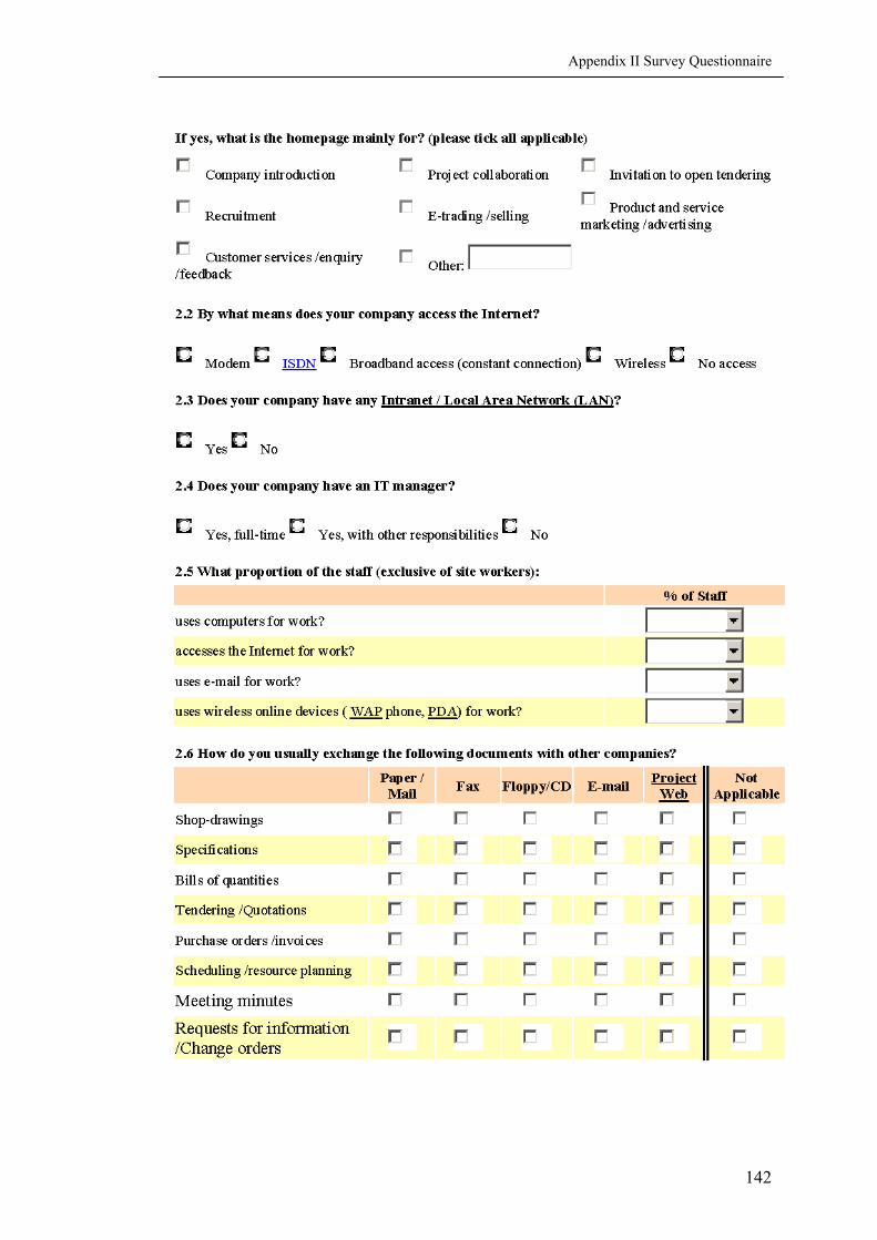
Appendix II Survey Questionnaire
142
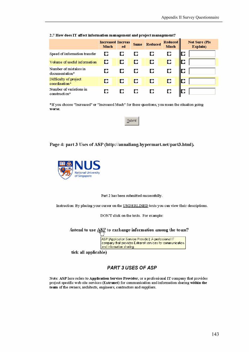
Appendix II Survey Questionnaire
143

Appendix II Survey Questionnaire
144

Appendix II Survey Questionnaire
145

Appendix II Survey Questionnaire
146

Appendix II Survey Questionnaire
147

Appendix II Survey Questionnaire
148

Appendix II Survey Questionnaire
149

Appendix II Survey Questionnaire
150

Appendix II Survey Questionnaire
151
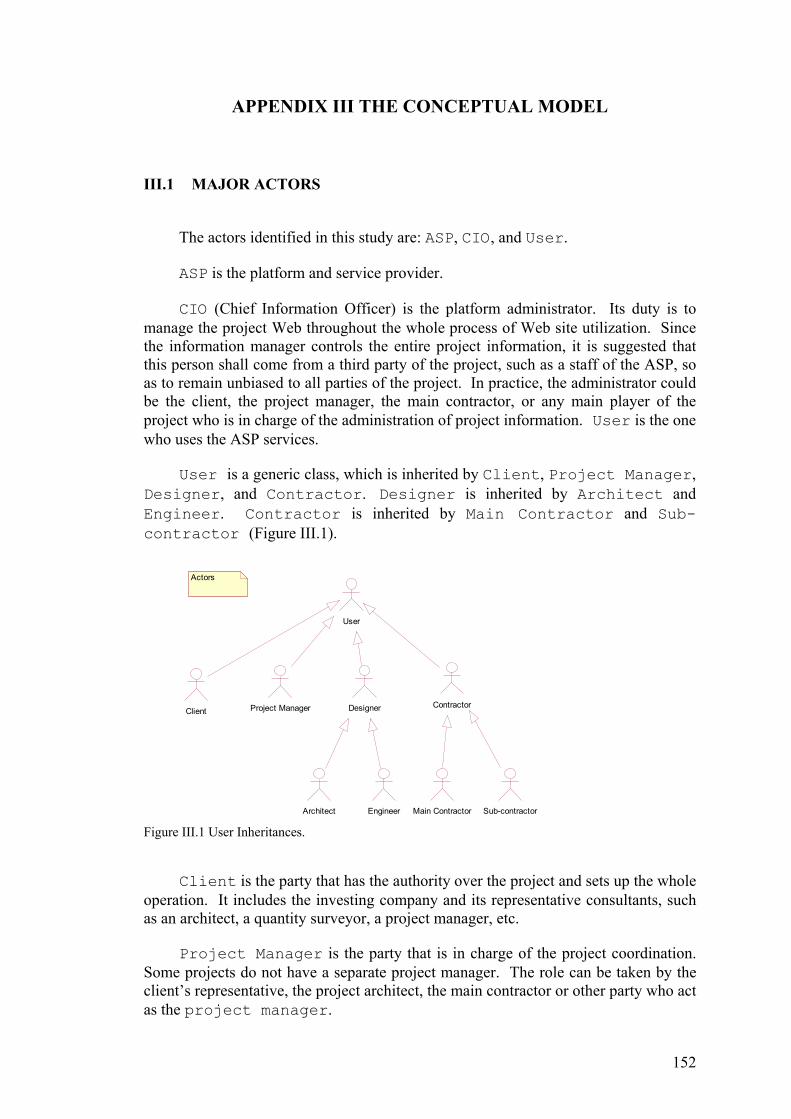
APPENDIX III THE CONCEPTUAL MODEL
III.1 MAJOR ACTORS
The actors identified in this study are: ASP, CIO, and User.
ASP is the platform and service provider.
CIO (Chief Information Officer) is the platform administrator. Its duty is to manage the project Web throughout the whole process of Web site utilization. Since the information manager controls the entire project information, it is suggested that this person shall come from a third party of the project, such as a staff of the ASP, so as to remain unbiased to all parties of the project. In practice, the administrator could be the client, the project manager, the main contractor, or any main player of the project who is in charge of the administration of project information. User is the one who uses the ASP services.
User is a generic class, which is inherited by Client, Project Manager, Designer, and Contractor. Designer is inherited by Architect and Engineer. Contractor is inherited by Main Contractor and Sub-contractor (Figure III.1).
User
Architect Engineer
Project Manager
Main Contractor Sub-contractor
ClientContractor
Actors
Designer
Figure III.1 User Inheritances.
Client is the party that has the authority over the project and sets up the whole operation. It includes the investing company and its representative consultants, such as an architect, a quantity surveyor, a project manager, etc.
Project Manager is the party that is in charge of the project coordination. Some projects do not have a separate project manager. The role can be taken by the client’s representative, the project architect, the main contractor or other party who act as the project manager.
152
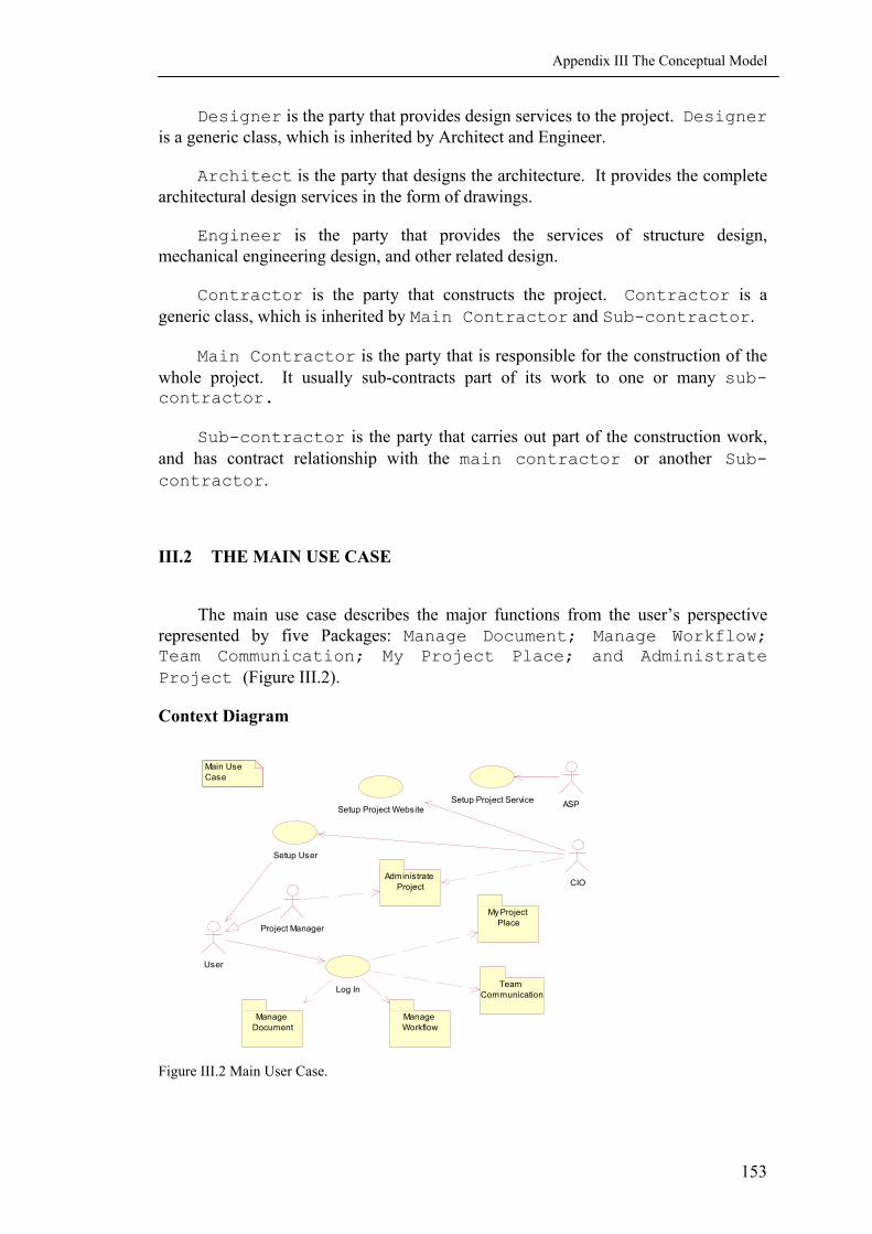
Appendix III The Conceptual Model
Designer is the party that provides design services to the project. Designer is a generic class, which is inherited by Architect and Engineer.
Architect is the party that designs the architecture. It provides the complete architectural design services in the form of drawings.
Engineer is the party that provides the services of structure design, mechanical engineering design, and other related design.
Contractor is the party that constructs the project. Contractor is a generic class, which is inherited by Main Contractor and Sub-contractor.
Main Contractor is the party that is responsible for the construction of the whole project. It usually sub-contracts part of its work to one or many sub-contractor.
Sub-contractor is the party that carries out part of the construction work, and has contract relationship with the main contractor or another Sub-contractor.
III.2 THE MAIN USE CASE
The main use case describes the major functions from the user’s perspective represented by five Packages: Manage Document; Manage Workflow; Team Communication; My Project Place; and Administrate Project (Figure III.2).
Context Diagram
Main Use Case
Project Manager
Setup Project Service ASPSetup Project Website
Log In
CIO
User
Setup User
Manage Document
Manage Workflow
Team Communication
My Project Place
Administrate Project
Figure III.2 Main User Case.
153

Appendix III The Conceptual Model
III.2.1 Setup Project Service
Actors
ASP
Brief Description
The use case sets up the application infrastructure for the project.
Main Flow
The use case begins when the client submits registration and billing information to the ASP. The ASP sends a confirm message (by email or by mail) to the client. The ASP assigns a URL to the project, allocates database space to the project, and links the URL to the web-based services it provides.
Activity Diagram
Client Registration
Submit Billing Information
Setup Project Service
Allocate Data Reository
Assign URL
Confirm Registration
Figure III.3 Setup Project Service.
Pre-Conditions
The project client understands the services and conditions of the ASP through discussion or negotiation. The client signs the contract with the ASP for web-based services.
Post-Conditions
If the use case was successful, the application services are ready for use. Otherwise, the system’s state is unchanged.
III.2.2 Setup Project Website
Brief Description
This use case is to set up default looks and functions for the website.
154

Appendix III The Conceptual Model
Actors
CIO
Main Flow
The CIO sets up the website framework based on templates provided by the ASP or past cases provided by the client. For Document Management, he defines the document directory, the document templates and creates the project portfolio with the templates. For Workflow Management, he defines business logic, assigns group permission rights to specific folders. He also defines the standard user interface. The business logics are the rules to govern the business processes, such as the process of change in Workflow Management, which will be discussed later.
Activity Diagram Setup Project Website
Define Document Templates
Define Workflow Templates
Define User Interface
Assign Group Permission Right
Define Document Directory
Define Business Logic
Figure III.4 Setup Project Website.
Pre-Conditions
The Web services are available.
Post-Conditions
If the use case was successful, the website is ready for use. Otherwise, the system’s state is unchanged.
III.2.3 Setup User
Brief Description
This use case is to setup the profile of the users that can access the project web and their rights to access information.
155

Appendix III The Conceptual Model
Actors
CIO
Main Flow
The use case begins when the CIO clicks Add A User in Administration.
The system requests the CIO to assign a user name to the user, enter the user’s profile, including basic information and administrative permission information. When the CIO clicks Submit, the system saves the basic information and permission information, generates password and user ID, and emails the login information to the user including his user name, password and the project URL.
Basic information is whatever can be filled in or modified by the users themselves: Organization, True Name (user name is usually the true name, except there are more than one user of the same true names), Company Address, Telephone Numbers, Fax Number, Email Address, Website. Administrative permission information is what can only be changed by the CIO and the Project Manager once it has been created: the Role that the user plays in the project (e.g., Client, Quantity Surveyor, Architect, Engineer, Project Manager, Main Contractor, Sub-Contractor, Supplier, etc), the information access rights, unique member ID assigned by the system, etc.
Alternative Flows
The email can not access the user. The system informs the CIO of the error. That email address is highlighted for amendment.
Activity Diagram Setup User
Assign User Name
Save Basic Information
Save Permission Information
Generate Password
Generate User ID
Send Log In Information
Send Error Message
Email Not Reach UserEmail Sent Successfully
Figure III.5 Setup User.
156

Appendix III The Conceptual Model
Pre-Conditions
The project space and project web site are ready to use.
Post-Conditions
If the use case was successful, the user details are saved to the database. Otherwise, the system’s state is unchanged.
III.2.4 Log In
Brief Description
This user case is to verify the user. If the project is highly security concerned, digital signature can substitute the process of user name and password.
Actors
User
Main Flow
This user case begins when the User assesses the project website and requests login. The system displays the login page. The User types his user name and password. When he clicks on Submit, the system verifies the user name and password. If they are correct, the What’s New page is displayed.
Alternative Flows
If the user name and password are incorrect, the system prompts the user to try again. The user can click on Forget password and answer some questions. If the answers are correct, password is emailed to him. If the answers are not all correct, or if the user fails in three attempts, he is blocked and prompted to contact the CIO for help.
Activity Diagram
Log In
Display Log In Page
Get User Name And Password
Verify User Name And Password
Display Error Message
Time Out
Display What's New
Invalid
OK
Figure III.6 Log In.
157

Appendix III The Conceptual Model
Pre-Conditions
The project website is ready to use. The User is assigned a user name and password for log in.
Post-Conditions
If the use case was success, the What’s New page is displayed. Otherwise, the system’s state is unchanged.
III.3 PACKAGE MY PROJECT PLACE
Context Diagram My Project Place
View What's New
Manage My Profile
View Webcam
Manage Subscription
User
(from Use Case View)
Figure III.7 Package My Project Place
III.3.1 View What’s New
Brief Description
This use case displays new information relevant to the User, especially the tasks to complete that day. The system displays the tasks assigned to the User that day (meetings, site visit, RFIs that need to respond to, etc), comments on tracked items in BBS or the files he uploaded, which the User can choose to view.
Actors
User
Main Flow
The system displays the What’s New page with the following contents generated from the respective use cases:
New task, from the user case View My Task. When viewing the new task, the User can carry out the task by invoking the user case Manage My Task.
158

Appendix III The Conceptual Model
New Comment, from the use case Display New Comment. When viewing the new comments, the User can make his own comments by invoking the use case Comment File from the Manage Document package.
New Correspondence, from the use case Display New Correspondence. When viewing the new correspondences, the User can reply email by invoking the use case Manage Email from the Team Communication package.
My Schedule, from the use case Display My Schedule. When viewing my schedule, the User can also view the project schedule by invoking the use case View Project Calendar from the Team Communication package.
Alternative Flows
If there is no new items, the system informs the User no new items to view.
Subordinate Use Cases Diagram
View What's New
Comment File
(from Manage Document)
Manage Email
(from Team Communication)
View Project Calendar
(from Team Communication)
Display New Comments
<<extend>>
Display New Correspondence
<<extend>>
Display My Schedule
<<extend>>
User
(from Use Case View)
Manage My TaskView My Task
<<extend>>
Figure III.8 View What’s New.
Pre-Conditions
The User logs in the project website successfully.
Post-Conditions
If the use case was success, the new items being responded are marked as read items and placed to respective categories. The new items not being responded remain in View What’s New. Otherwise, they system’s state is unchanged.
III.3.2 Manage My Task
Brief Description
The use case is for the User to manage his own tasks.
Actors
User
159

Appendix III The Conceptual Model
Main Flow
The use case begins when the User clicks on Manage My Task. The system displays the User’s tasks.
The User can view his tasks, respond to the tasks. He can also organize the tasks by subject or by other user-defined criteria. When the task is done, he can close it.
Alternative Flow
Task does not exist. The system tells the User to manage his tasks later when they are assigned to him.
Sequence Diagram Manage My Task
View Task
Respond Task
Close Task
Organize Task
Figure III.9 Manage My Task.
Pre-Conditions
The User logs in the project website successfully.
Post-Conditions
The system updates its database. The read tasks are marked as Read. The responded tasks are marked Responded. The closed tasks are marked Closed.
III.3.3 Manage My Profile
Brief Description
The use case is for the User to manage his own profile, including to change his contact information, and to view his activities on the project website, etc.
160
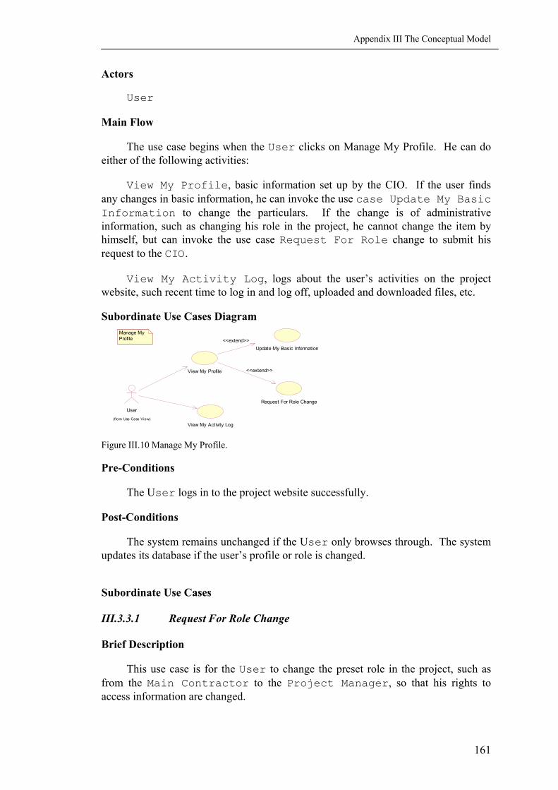
Appendix III The Conceptual Model
Actors
User
Main Flow
The use case begins when the User clicks on Manage My Profile. He can do either of the following activities:
View My Profile, basic information set up by the CIO. If the user finds any changes in basic information, he can invoke the use case Update My Basic Information to change the particulars. If the change is of administrative information, such as changing his role in the project, he cannot change the item by himself, but can invoke the use case Request For Role change to submit his request to the CIO.
View My Activity Log, logs about the user’s activities on the project website, such recent time to log in and log off, uploaded and downloaded files, etc.
Subordinate Use Cases Diagram Manage My Profile
View My Activity Log
User
(from Use Case View)
Update My Basic Information
Request For Role Change
View My Profile
<<extend>>
<<extend>>
Figure III.10 Manage My Profile.
Pre-Conditions
The User logs in to the project website successfully.
Post-Conditions
The system remains unchanged if the User only browses through. The system updates its database if the user’s profile or role is changed.
Subordinate Use Cases III.3.3.1 Request For Role Change
Brief Description
This use case is for the User to change the preset role in the project, such as from the Main Contractor to the Project Manager, so that his rights to access information are changed.
161

Appendix III The Conceptual Model
Actor
User
Main Flow
The use case begins when the User clicks on Request To Change Role. The system displays the form for his request. When he clicks Submit, the system sends the request to the CIO. After investigation with the higher level authority in the project, such as the client, the CIO approves the request and updates the user’s role. The system emails to inform the User his new role and access rights.
Alternative Flow
After investigating with the higher level authority in the project, the CIO rejects the request. The role remains unchanged. The system informs the User of the result, with the reasons presented by the CIO.
Activity Diagram
Get Request For Role Change
Request For Role Change
Send Request to Administrator
Update RoleRemain Role
Inform User
ApprovedDenied
Figure 5.11 Request For Role Change.
Pre-Conditions
The User logs in to the project website successfully.
Post-Conditions
The system remains unchanged if the User only browses his profiles. The system updates its database if the user’s role is changed.
162

Appendix III The Conceptual Model
III.3.4 Manage Subscription
Brief Description
This use case is for subscription and un-subscription to the industry information services and to the tracked items in the project.
Actors
User
Main Flow
The use case begins when the User clicks on Manage Subscription. He can do either of the following activities:
View Available Industry Information. He browses through available industry information services on the Internet. If any topic interests him, he can invoke the use case Subscribe to subscribe to that service. The system bookmarks the URL for easy access to the service.
View Bookmarked Industry Information. He browses through the subscribed services. If he considers a service is no longer useful, he can invoke the user case Unsubscribe to delete the bookmark.
View Tracked File. The tracked files are organized in the categories of drawings, schedules, costs and other directories indicated by the CIO or the user himself. A file can only be tracked if the User has the access right to view it. If the User finds that a file is no longer needed to be tracked, he can invoke the use case Unsubscribe to delete it from the tracked list.
View Tracked Discussion. The tracked discussions are specific topics in the BBS that the project parties are discussing on. If a discussion is finished, the User can invoke the use case Unsubscribe to delete it from the tracked list.
Alternative Flows
There is no subscription to any industry information or project item. The system tells the User how to use these features.
163
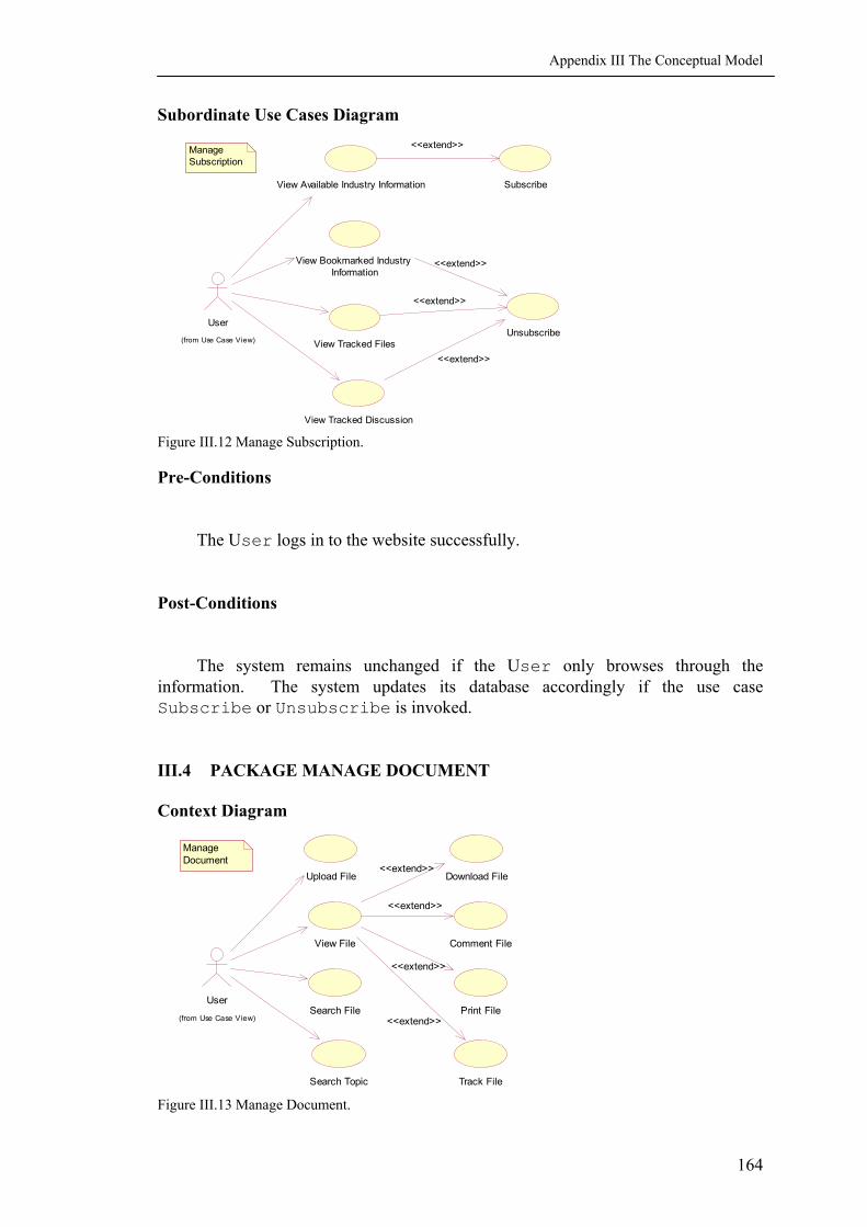
Appendix III The Conceptual Model
Subordinate Use Cases Diagram
SubscribeView Available Industry Information
<<extend>>
View Bookmarked Industry Information
View Tracked Files
User
(from Use Case View)Unsubscribe
<<extend>>
<<extend>>
View Tracked Discussion
<<extend>>
Manage Subscription
Figure III.12 Manage Subscription.
Pre-Conditions
The User logs in to the website successfully.
Post-Conditions
The system remains unchanged if the User only browses through the information. The system updates its database accordingly if the use case Subscribe or Unsubscribe is invoked.
III.4 PACKAGE MANAGE DOCUMENT
Context Diagram
Manage Document
Download File
Comment File
Print File
Track File
View File
<<extend>>
<<extend>>
<<extend>>
<<extend>>Search File
Search Topic
Upload File
User
(from Use Case View)
Figure III.13 Manage Document.
164

Appendix III The Conceptual Model
Manage Document Inheritance
Manage Document
Manage Drawing
Manage Schedule
Manage Cost
Manage Document Inheritance
Manage User Defined Document Figure III.14 Manage Document Inheritance.
III.4.1 Upload File
Brief Description
This use case is for file uploading. Meta data of the file is required to ease the search of the file on the project website once it is uploaded. User can once upload one file or a batch of files.
Actors
User
Main Flow
The use case begins when the User clicks on Upload File. The system displays the upload webpage. The User indicates the location of the file by typing the path or by clicking the Browse button to browse through the location. He indicates the category that the file should be uploaded to.
The system verifies whether the file format is valid for upload. It also searches its file index to see whether a file of the same name exists. The system assigns a version number to the valid format file, and displays default meta data for the user to review. It also prompts the User to fill in other meta data. When the User clicks on Submit, the system checks whether the file name has been changed by the User. If file name is not changed, it uploads the file to the database and updates file index for search. It also assigns a unique file ID to the file, saves the meta data and updates its topic index for topic search. The system will also informs the users who has required to track changes of that file.
Alternative Flows
The file format is invalid. The system prompts the User to upload a valid format file.
165

Appendix III The Conceptual Model
The file name is changed by the User, the system verify the file name again and assigns version number to the file, displays the default meta data, and prompts the User to fill in other meta data, if any.
Activity Diagram Upload File
Display Upload Page
Get File Location
Verify File Format
Verify File Name
Prompt To Upload Valid Format File
Assign Version No.
Display Default Meta Data
File Name Changed
Upload File
Save Meta Data
Inform Relevent User
Update Topic Index
Assign File ID
Update File Index
File Name Not Change
Invalid Format
Valid Format
Figure III.15 Upload File.
Pre-Conditions
The User logs in to the project website successfully.
Post-Conditions
If the use case was successful, the system updates its database.
III.4.2 Search File
Brief Description
This use case is for file searching. The system should only returns files that the User has access right to view.
Actors
User
Main Flow
This user case begins when the User clicks on Search Files. The system displays search page with various search criteria, such as:
166

Appendix III The Conceptual Model
Meta data: searching for a document using the meta data entered, e.g., author, date, description, etc.
Keyword: keying in a keyword, and the search engine finds the most matches.
Catalogue: browsing through the catalogues and sub-catalogues to locate information.
Full text: searching in the entire content of the documents.
When the User clicks on Submit, the system gets the search criteria, searches its file index, and returns the search result with links to the location of the files.
Alternative Flows
No match is found. The system returns the result and displays instructions for search.
Activity Diagram
Search File
Display File Search Page
Get Search Criteria
Search File Index
Display Search Result
Figure III.16 Search File.
Pre-Conditions
The User logs in to the project website successfully.
Post-Conditions
The system remains unchanged, except counting the most frequent searches.
III.4.3 Search Topic
Brief Description
This use case is for integrated information search and display. The system should only return information that the User has access right to view.
Actors
User
167

Appendix III The Conceptual Model
Main Flow
This use case begins when the User click on Search A Topic. The system displays topic search page with various search criteria.
When the User clicks on Submit, the system gets the search criteria, searches its topic index, and displays the search result.
The User browses through the result and marks useful items. Information that is written in or can be transformed to XML format can be copied and pasted to the Saved Items. Information in XML incompatible format can be saved as the whole file is. The User can save the marked information for future use, or request another search.
When the User gets enough information, he can review the saved item list, indicates how he want the information to be displayed. The system displays the information in one integrated webpage.
The integrated webpage can be saved to the User Defined Document in Document Management for permanent use, or linked to the user’s My Work Package in Workflow Management for short-term use.
Alternative Flows
No match is found. The system returns the result and displays instructions for search.
Activity Diagram
Display Topic Search Page
Display Itegrated Information
Get Display Choice
Display Search Result
Search Topic Index
Get Search Criteria
Search Topic
Browse Search Result
Mark Useful Information
Save Marked Information
Save Search Result
More Information Needed Get Enough Information
Figure III.17 Search Topic.
168

Appendix III The Conceptual Model
Pre-Conditions
The User logs in to the project website successfully.
Post-Conditions
The system saves the search results and integrated webpages to its database.
III.5 PACKAGE MANAGE WORKFLOW
Context Diagram
Manage Workflow
Manage Change
Manage Purchase Order
Manage Meeting Minute
Manage TransmittalsUser
(from Use Case View)
Manage Field Report
Manage Material
Manage My Work Package
Manage My Task
(from My Project Place)
<<extend>>
Contractor
(from Use Case View)Mange Sub-contract
Figure III.18 Manage Workflow.
III.5.1 Manage Change
Brief Description
This use case is to manage the changes in construction.
Actors
User
169
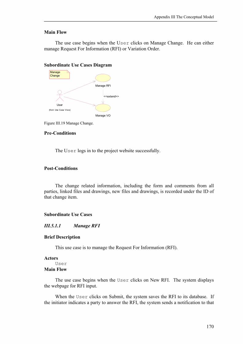
Appendix III The Conceptual Model
Main Flow
The use case begins when the User clicks on Manage Change. He can either manage Request For Information (RFI) or Variation Order.
Subordinate Use Cases Diagram
User
(from Use Case View)
Manage Change
Manage RFI
Manage VO
<<extend>>
Figure III.19 Manage Change.
Pre-Conditions
The User logs in to the project website successfully.
Post-Conditions
The change related information, including the form and comments from all parties, linked files and drawings, new files and drawings, is recorded under the ID of that change item.
Subordinate Use Cases
III.5.1.1 Manage RFI
Brief Description
This use case is to manage the Request For Information (RFI).
Actors User
Main Flow
The use case begins when the User clicks on New RFI. The system displays the webpage for RFI input.
When the User clicks on Submit, the system saves the RFI to its database. If the initiator indicates a party to answer the RFI, the system sends a notification to that
170

Appendix III The Conceptual Model
party. If not, the system sends the notification to the Project Manager, so that he will assign task to the responsible party.
The responsible User receives the notification, views the RFI, and answers the RFI.
The system saves the answer, notifies the initiator and the Project Manager.
If the initiator is satisfied with the answer, he closes the RFI and the workflow ends.
Alternative Flows
If the RFI needs more clarification, the responsible User adds his comments and redirects the RFI back to the initiator. The initiator clarifies his question and submits it again.
If the responsible User cannot answer the RFI, he adds his comments, redirects the RFI to a User who can answer the RFI. The new responsible party goes through viewing and replying RFI or redirecting it to another responsible party, until one party answers the question. The system records the comments and history of information redirects.
If the initiator is not satisfied with the answer, he adds his comment and sends the RFI back to the responsible party. The responsible party goes through viewing and replying RFI or redirecting it to another responsible party.
Activity Diagram
Create RFI
Submite RFI
Reply RFI
View RFI
Redirect RFIRequire Clarification
Close RFI
Workflow of RFI
Able to Answer
Unable to AnswerQuestion Not Clear
Satisfied With ResponseNot Satisfied With Response
Figure III.20 Workflow of RFI.
171

Appendix III The Conceptual Model
Pre-Conditions
The User logs in to the project website successfully.
Post-Conditions
The RFI related information, including the RFI form and comments from all parties, linked files and drawings, new files and drawings, is recorded under the ID of that RFI.
III.5.1.2 Manage Variation Order
Brief Description
This use case is to manage the Variation Order (VO) in construction. VO is usually generated from RFI.
Actors
User
Main Flow
The use case begins when the User clicks on New VO. The system displays the webpage for VO input.
When the User clicks on Submit, the system saves the VO to its database. If the initiator indicates a party to respond to the VO, the system sends a notification to that party. If not, the system sends the notification to the Project Manager, so as to assign task to the party that is responsible.
The responsible User receives the notification, views the VO, and approves the VO.
The system saves the approval, notifies the initiator and the Project Manager. If the initiator is satisfied with the answer, he closes the VO and the workflow ends.
Alternative Flows
If the VO needs more clarification, the responsible User adds his comments and redirects the VO back to the initiator. The initiator clarifies his VO and submits it again.
If the responsible User rejects the VO, he adds his reasons and comments, redirects the VO to the initiator. The use case ends.
If the responsible User approves the VO but he is not the person making final decision, the VO is forwarded to other responsible parties for approval. The other responsible parties go through viewing and approving the VO, or rejecting the VO, until the final decision is made.
172

Appendix III The Conceptual Model
Activity Diagram Workflow of VO
Create VO
Submit VO
View VO
Approve VORequire Clarification
Reject VO
VO Not Clear
Need Comment From Other Party
Close VO
Final Decision Made
Close VO
Figure III.21 Workflow of VO.
Pre-Conditions
The User logs in to the project website successfully.
Post-Conditions
The VO related information, including the VO form and comments from all parties, linked files and drawings, new files and drawings, is recorded under the ID of that VO.
III.5.2 Manage My Work Package
Brief Description
This use case is to create personalized work package to include all related information to a work item, such as a RFI, or a Purchase Order (PO).
Actors
User
Main Flow
The use case begins when the User clicks on Create New Package. The system displays the webpage for package input.
173

Appendix III The Conceptual Model
The User indicates the name of the work package, adds links to workflow, documents, tasks, integrated files generated from topic search, and other necessary information. The system saves the above information under the ID of that work flow.
The user can edit the work package by adding and deleting links and files in the package as the work goes on.
Activity Diagram
Create Work Package
Link Document
Link Workflow
Link Task
Manage My Work Package
Figure III.22 Manage My Work Package. Pre-Conditions
The User logs in to the project website successfully.
Post-Conditions
The system saves the links in the work package and updates any edition to the links.
III.6 PACKAGE TEAM COMMUNICATION
Context Diagram
Manage Email
Instance Messaging
BBS
Online Conference
View Project CalendarView Contact
User
(from Use Case View)
Team Communication
Figure III.23 Team Communication.
174

Appendix III The Conceptual Model
III.6.1 View BBS
Brief Description
This use case is for informal discussion of a topic. Its use with Workflow Management can simplify the workflow processes.
Actors
User
Main Flow
The use case begins when the User clicks on View BBS. The system displays the most recent discussion topics.
The User can add a new topic to the BBS, or edit his posts.
The user can also read posted articles, respond to articles that need his reply. He may provide information to answer the question by referring a file, or invoking Search Topic to search integrated information.
Subordinate Use Cases Diagram View BBS
Edit Article
Refer A File
Add New Article
<<extend>>
Reply Article
<<extend>>
User
(from Use Case View)
Search Topic
(from Manage Document)
Read Posted Article
<<extend>>
<<extend>>
Figure III.24 View BBS.
Pre-Conditions
The User logs in to the project website successfully.
Post-Conditions
All the posts are saved to the system.
175

Appendix III The Conceptual Model
176
III.7 PACKAGE ADMINISTRATE PROJECT
Context Diagram
Maintain User
Manage User
Manage File
Manage Activity
Project Manager
(from Use Case View)
Setup User
(from Use Case View)
CIO
(from Use Case View)
Administrate Project
Figure III.25 Administrate Project.
III.7.1 Setup User
See the use case Setup User in Main use case.

APPENDIX IV XML DOCUMENTS FOR RERFI
Chapter 6 presents schema and xml file of a Response To Request For Information (ReRFI). Here we present the schema and xml files of the Request For Information, the Response To Request For Information, the Quotation, and the Quotation For Change. All schema and xml files are edited with the software XMLSPY (XMLSPY, 2002).
IV.1 HTML FILE OF RERFI
Figure IV.1 HTML Webpage of ReRFI.
177

Appendix IV XML Documents For ReRFI
Figure IV.1 HTML Webpage of ReRFI (Continue).
178
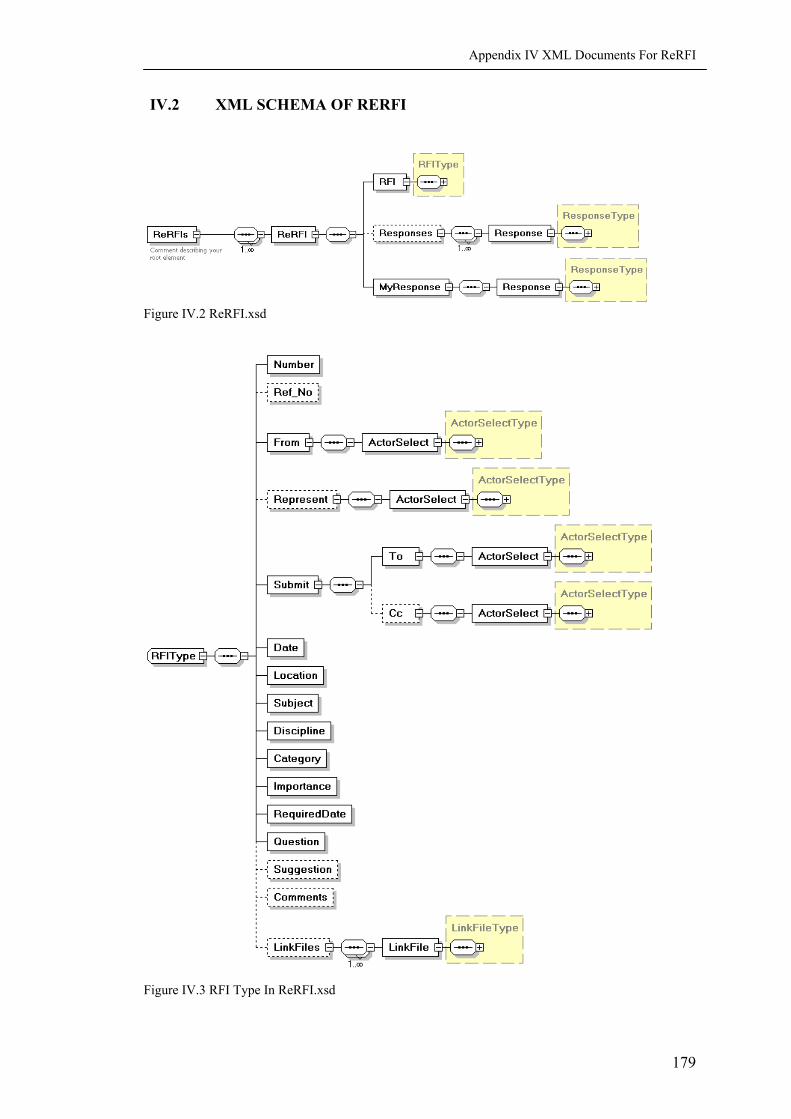
Appendix IV XML Documents For ReRFI
IV.2 XML SCHEMA OF RERFI
Figure IV.2 ReRFI.xsd
Figure IV.3 RFI Type In ReRFI.xsd
179

Appendix IV XML Documents For ReRFI
Figure IV.4 Response Type in ReRFI.xsd
Figure IV.5 LinkFile Type in ReRFI.xsd
Figure IV.6 ActorSelect Type in ReRFI.xsd
180

Appendix IV XML Documents For ReRFI
IV.3 SOURCE CODES OF RERFI SCHEMA
<?xml version="1.0" encoding="UTF-8"?> <!-- edited with XML Spy v4.4 (http://www.xmlspy.com) by Leung Nga Na (NUS) --> <xs:schema xmlns:xs="http://www.w3.org/2001/XMLSchema" elementFormDefault="qualified" attributeFormDefault="unqualified"> <xs:element name="ReRFIs"> <xs:annotation> <xs:documentation>Comment describing your root element</xs:documentation> </xs:annotation> <xs:complexType> <xs:sequence maxOccurs="unbounded"> <xs:element name="ReRFI"> <xs:complexType> <xs:sequence> <xs:element name="RFI"> <xs:complexType> <xs:sequence> <xs:element name="Number"/> <xs:element name="Ref_No" minOccurs="0"/> <xs:element name="From"> <xs:complexType> <xs:sequence> <xs:element name="ActorSelect" type="ActorSelectType"/> </xs:sequence> </xs:complexType> </xs:element> <xs:element name="Represent" minOccurs="0"> <xs:complexType> <xs:sequence> <xs:element name="ActorSelect" type="ActorSelectType"/> </xs:sequence> </xs:complexType> </xs:element> <xs:element name="Submit"> <xs:complexType> <xs:sequence> <xs:element name="To"> <xs:complexType> <xs:sequence> <xs:element name="ActorSelect" type="ActorSelectType"/> </xs:sequence> </xs:complexType> </xs:element> <xs:element name="Cc" minOccurs="0"> <xs:complexType> <xs:sequence> <xs:element name="ActorSelect" type="ActorSelectType"/> </xs:sequence> </xs:complexType> </xs:element> </xs:sequence> </xs:complexType> </xs:element> <xs:element name="Date"/> <xs:element name="Location"/> <xs:element name="Subject"/> <xs:element name="Discipline"/> <xs:element name="Category"/> <xs:element name="Importance"/> <xs:element name="RequiredDate"/> <xs:element name="Question"/> <xs:element name="Suggestion" minOccurs="0"/> <xs:element name="Comments" minOccurs="0"/> <xs:element name="LinkFiles" minOccurs="0"> <xs:complexType>
181

Appendix IV XML Documents For ReRFI
<xs:sequence maxOccurs="unbounded"> <xs:element name="LinkFile" type="LinkFileType"/> </xs:sequence> </xs:complexType> </xs:element> </xs:sequence> </xs:complexType> </xs:element> <xs:element name="Responses" minOccurs="0"> <xs:complexType> <xs:sequence maxOccurs="unbounded"> <xs:element name="Response" type="ResponseType"/> </xs:sequence> </xs:complexType> </xs:element> <xs:element name="MyResponse"> <xs:complexType> <xs:sequence> <xs:element name="Response" type="ResponseType"/> </xs:sequence> </xs:complexType> </xs:element> </xs:sequence> </xs:complexType> </xs:element> </xs:sequence> </xs:complexType> </xs:element> <xs:complexType name="ActorSelectType"> <xs:sequence> <xs:element name="Person"/> <xs:element name="Organization"/> </xs:sequence> </xs:complexType> <xs:complexType name="LinkFileType"> <xs:sequence> <xs:element name="Name"/> <xs:element name="FileID"/> <xs:element name="Location"/> <xs:element name="Description" minOccurs="0"/> <xs:element name="Private" minOccurs="0"/> <xs:element name="Display" minOccurs="0"/> </xs:sequence> </xs:complexType> <xs:complexType name="ResponseType"> <xs:sequence> <xs:element name="ResponseID"/> <xs:element name="Date"/> <xs:element name="Answer" minOccurs="0"/> <xs:element name="Co_Respondent" minOccurs="0"> <xs:complexType> <xs:sequence> <xs:element name="ActorSelect" type="ActorSelectType"/> </xs:sequence> </xs:complexType> </xs:element> <xs:element name="Comments" minOccurs="0"/> <xs:element name="LinkFiles" minOccurs="0"> <xs:complexType> <xs:sequence maxOccurs="unbounded"> <xs:element name="LinkFile" type="LinkFileType"/> </xs:sequence> </xs:complexType> </xs:element> <xs:element name="Submit" minOccurs="0"> <xs:complexType> <xs:sequence> <xs:element name="To"> <xs:complexType> <xs:sequence> <xs:element name="ActorSelect" type="ActorSelectType"/>
182

Appendix IV XML Documents For ReRFI
</xs:sequence> </xs:complexType> </xs:element> <xs:element name="Cc" minOccurs="0"> <xs:complexType> <xs:sequence> <xs:element name="ActorSelect" type="ActorSelectType"/> </xs:sequence> </xs:complexType> </xs:element> </xs:sequence> </xs:complexType> </xs:element> <xs:element name="ReDirect" minOccurs="0"> <xs:complexType> <xs:sequence> <xs:element name="To"> <xs:complexType> <xs:sequence> <xs:element name="ActorSelect" type="ActorSelectType"/> </xs:sequence> </xs:complexType> </xs:element> <xs:element name="Cc" minOccurs="0"> <xs:complexType> <xs:sequence> <xs:element name="ActorSelect" type="ActorSelectType"/> </xs:sequence> </xs:complexType> </xs:element> </xs:sequence> </xs:complexType> </xs:element> </xs:sequence> </xs:complexType> </xs:schema>
183
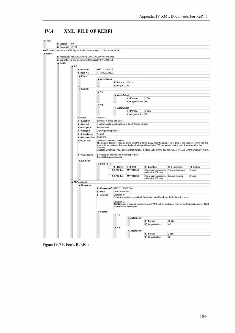
Appendix IV XML Documents For ReRFI
IV.4 XML FILE OF RERFI
Figure IV.7 K Foo’s ReRFI.xml
184

Appendix IV XML Documents For ReRFI
IV.5 SOURCE CODES OF RERFI XML
<?xml version="1.0" encoding="UTF-8"?> <!-- edited with XML Spy v4.4 (http://www.xmlspy.com) by Leung Nga Na (NUS) --> <ReRFIs xmlns:xsi="http://www.w3.org/2001/XMLSchema-instance" xsi:noNamespaceSchemaLocation="C:\My Documents\DemoWeb\RFI\ReRFI.xsd"> <ReRFI> <RFI> <Number>MRT/112034525</Number> <Ref_No>RFI/FNCAS/1522</Ref_No> <From> <ActorSelect> <Person>YS Liu </Person> <Organization>MC</Organization> </ActorSelect> </From> <Submit> <To> <ActorSelect> <Person>K Foo</Person> <Organization>AR</Organization> </ActorSelect> </To> <Cc> <ActorSelect> <Person>C Tan</Person> <Organization>CL</Organization> </ActorSelect> </Cc> </Submit> <Date>18/10/2001</Date> <Location>Entrance 1 of GB Staircase</Location> <Subject>Handrail position and material at GL (RA) side parapet</Subject> <Discipline>Architectural</Discipline> <Category>Drawing Discrepancies</Category> <Importance>Normal</Importance> <RequiredDate>20/10/2001</RequiredDate> <Question>Question 1: Handrail position The original design of handrail along GL(RA) is 80mm away from the parapet wall. Due to the position conflict with the steel column footing at this side, the handrail should be at least 200 mm away from the wall. Please confirm the distance. Question 2: Handrail material Handrail material is not specified in the original design. Please confirm whether Type 316 or Type 304 is to use.</Question> <Suggestion>See attached drawings for handrail position. Type 304 is recommended.</Suggestion> <Comments/> <LinkFiles> <LinkFile> <Name>C709.dwg</Name> <FileID>MRT112343</FileID> <Location>/drawings/shopdrawings/details/C709.dwg</Location> <Description>Proposed drawing</Description> <Display>Embed</Display> </LinkFile> <LinkFile> <Name>C709.dwg</Name> <FileID>MRT112056</FileID> <Location>/drawings/shopdrawings/details/C709.dwg </Location> <Description>Original drawing</Description> <Display>Embed</Display> </LinkFile> </LinkFiles> </RFI> <MyResponse> <Response> <ResponseID>MRT/112034525Re1</ResponseID> <Date>Date 24/10/2001</Date>
185
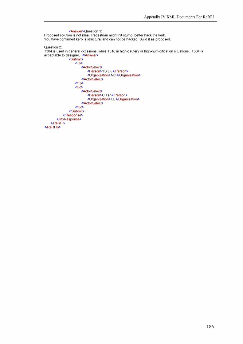
Appendix IV XML Documents For ReRFI
186
<Answer>Question 1: Proposed solution is not ideal; Pedestrian might hit stump, better hack the kerb. You have confirmed kerb is structural and can not be hacked. Build it as proposed. Question 2: T304 is used in general occasions, while T316 in high-cautery or high-humidification situations. T304 is acceptable to designer. </Answer> <Submit> <To> <ActorSelect> <Person>YS Liu</Person> <Organization>MC</Organization> </ActorSelect> </To> <Cc> <ActorSelect> <Person>C Tan</Person> <Organization>CL</Organization> </ActorSelect> </Cc> </Submit> </Response> </MyResponse> </ReRFI> </ReRFIs>