Working-Fluid Selection for Minimized Thermal Resistance ...
A Computer Program for Working Fluid Selection of
Low Temperature Organic Rankine Cycle
Muhammad Ansab Ali Mechanical Engineering Department,
The Petroleum Institute, Abu Dhabi UAE Email: [email protected]
Tariq Saeed Khan
Mechanical Engineering Department, The Petroleum Institute, Abu Dhabi UAE
Email: [email protected]
Ebrahim Al Hajri Mechanical Engineering Department,
The Petroleum Institute, Abu Dhabi UAE
Email: [email protected]
Zahid H. Ayub Isotherm Inc. 7401 Commercial Blvd. East
Arlington, Texas 76001 USA,
Email: [email protected]
ABSTRACT
Fossil fuels are continuously depleting while the global energy demand is growing at a fast rate. Additionally, fossil fuels based power plants contribute to environmental pollution. Search for alternate energy resources and use of industrial waste heat for power production are attractive topics of interest these days. One way of enhancing power production and decreasing the environmental impact is by recuperating and utilizing low grade thermal energy. In recent years, research on use of organic Rankine cycle (ORC) has gained popularity as a promising technology for conversion of heat into useful work or electricity. Due to simple structure of ORC system, it can be easily integrated with any energy source like geothermal energy, solar energy and waste heat. A computer program has been developed in engineering equation solver (EES) environment that analyzes and selects appropriate working fluid for organic Rankine cycle design based on available heat sources. For a given heat source, the program compares energy and exergy performance of various working fluids. The program also includes recuperator performance analysis and compares its effectiveness on the
overall thermal performance of the Rankine cycle. This program can assist in preliminary design of ORC with respect to best performing refrigerant fluid selection for the given low temperature heat source.
INTRODUCTION
The current global energy demand is increasing on a tremendous rate due to increasing population and technological growth. Fossil fuels make the largest percentage of the World’s total energy production. Due to this rise in energy demand, interest in renewable energy sources and waste heat utilization in power production has gained popularity in recent years. Organic Rankine cycle (ORC) is one of the attractive choices to convert waste heat into useful work. It requires low to medium temperature heat sources for its operation [1]. Adoption of such a thermal cycle also contributes to environmental protection.
In this paper an overview of the types of fluids, fluid characteristics, working of a computer code for analysis and working fluid selection are presented. Two case studies are discussed and results presented.
Proceedings of the ASME 2015 Power Conference POWER2015
June 28-July 2, 2015, San Diego, California
POWER2015-49691
1 Copyright © 2015 by ASME

Working fluids and Characteristics
Thermodynamics characteristics like cycle efficiency and power
output are strongly coupled with the working fluid used in organic Rankine cycle. Based on the slope of saturation vapor
curve (dT/ds), working fluids are defined as dry, wet and isentropic fluids having positive, negative and infinite slope
respectively as displayed in the Figure 1.
Figure 1 Types of working fluids (a- dry, b- wet, c- isentropic) based on saturation vapor curve [2]
Dry and isentropic fluids are preferred for ORC applications as
vapor formation in the expansion machine is avoided. Moreover, the efficiency can be enhanced by using recuperator.
Critical pressure and temperature of the working fluids are
important characteristics in defining the pressure ranges of the cycle. Drescher et al. [3] proposed to set the maximum pressure to be 100kPa less than the critical pressure. Torres et al. [4]
chose the maximum temperature to be 15°K less than the critical temperature of the fluid. In the present work we have considered
the maximum pressure of the cycle to be less than 0.9 times the critical pressure so that the vapor formation in the expansion may be avoided.
A high vapor density is preferred as this leads to the less volume flow rate in the exchangers and consequently small pressure drops and small size of the expansion machine.
Low viscosity and high thermal conductivity is desired as this will lead to higher heat transfer coefficient and less pressure drop.
The melting point of the working fluid should be lower than the minimum cycle temperature in order to avoid freezing the cycle. The condensing pressure should be such that impurities infiltration from the surroundings is avoided.
Environmental characteristics like ozone depletion potential, global warming potential should also be considered while selecting refrigerants. ASHRAE Standard 34 provides valuable guidelines for the safety and environmental impacts of the refrigerants.
THERMODYNAMIC CYCLE
Using unconventional fluids in Rankine cycle enables us to utilize heat at low temperature. In case of dry and isentropic fluids, the fluid state after the expansion machine is usually superheated and this available heat can be captured by using recuperator to preheat the fluid leaving the pump. A schematic
of recuperated organic Rankine cycle is given in Figure 2 which consists of five main components; evaporator, expansion machine, recuperator, condenser and pump.
Figure 2 Schematic of Organic Rankine Cycle with Recuperator
Temperature entropy diagram of an ORC with recuperator is
shown in the Figure 3.
Figure 3 Temperature entropy diagram of Organic Rankine Cycle with Recuperator
2 Copyright © 2015 by ASME

The first and second law energy analysis of the cycle results in following equations:
Evaporator �̇�� = �̇��ℎ���� − ℎ������� (1)
Expander �̇��� = �̇�(ℎ���� − ℎ�����) (2)
Recuperator Q̇rec= έ���. ����������� − ������ (3)
Q̇rec= �̇�(ℎ����� − ℎ���� ) (4)
Q̇rec= �̇��ℎ������ − ℎ����� (5)
Condenser �̇��� = �̇�(ℎ���� − ℎ�����) (6)
Pump �̇���� = �̇��ℎ���� − ℎ���� (7)
Net Power
Output �̇����� = �̇��� − �̇���� (8)
Thermal Efficiency
� =�̇�����
�̇��
(9)
Exergetic
Efficiency of Evaporator
����� =�̇������� − ��������
�̇�(���� − �����) (10)
Flow Exergy (11)
����� − ������ = ℎ���� − ℎ����� − ���������� − ��������
����� − ������ = ℎℎ�� − ℎℎ��� − ����(�ℎ�� − �ℎ���)
Exergy Destruction ���� = ����(�) (12)
���� = �̇�(������ − �����) (13)
����� = �̇������� − ����� (14)
����� = �̇���exin − �evapin� + �̇ℎ(�ℎ��� − �ℎ��) (15)
��� = �̇�������� − ����� � + �̇������� − ����
� (16)
Flow chart of Computer Program
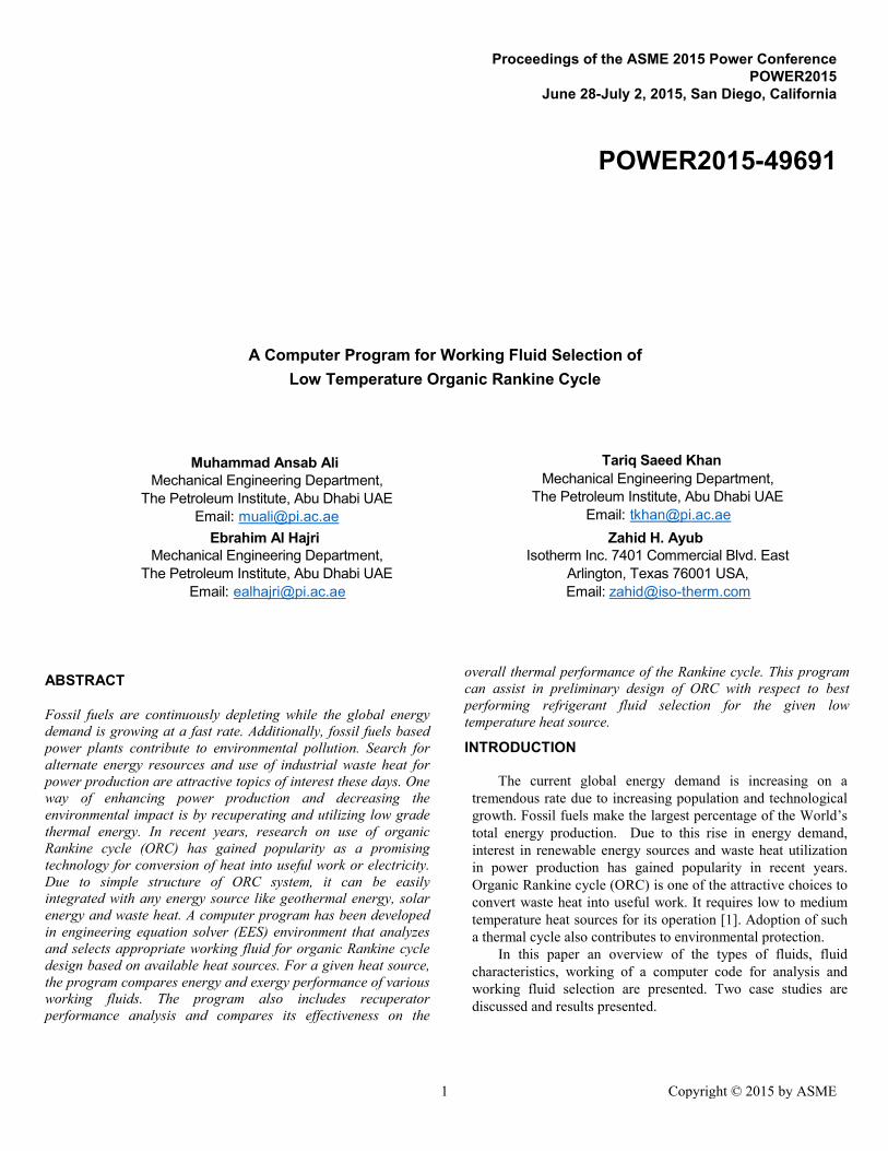
The baseline of the program is that a particular working fluid is considered for analysis at a pre-set condenser temperature. For the given working fluid, setting an evaporator pressure at a low starting value, the system thermal and evaporator exergetic efficiencies are determined and values stored. Then the evaporator pressure is increased by a small increment as displayed in Figure 4 and new efficiency values are stored. This procedure continues till the evaporator pressure reaches 0.90 times the critical pressure of that working fluid. This limit has been set as the maximum allowable pressure in the evaporator. However, the minimum pinch point at the evaporator is set to a specific value. Then the next working fluid is analyzed in a similar fashion and respective parameters are determined. The working fluid that gives the most optimum values of evaporator exergetic efficiency and overall cycle thermal efficiency is presented to the user for final selection. The flow chart of the program is given in the Figure 5.
In the computer program, cycle is analysed for steady state, steady flow conditions while zero pressure drop across the exchangers and associated piping systems is assumed. Adiabatic conditions exists in pump and expansion machine. A sensible heat source like air, water or steam (noncondensing) is assumed while developing the program.
Figure 4 Pressure Increment in cycle analysis
3 Copyright © 2015 by ASME
Results and Discussion
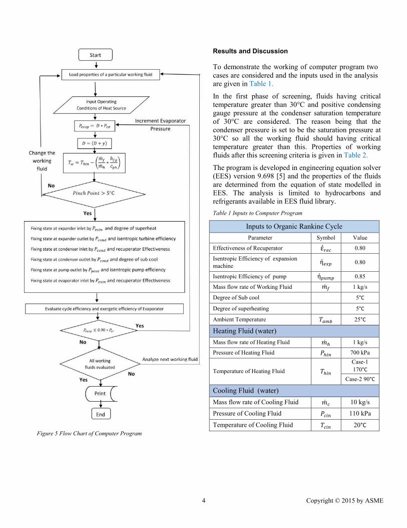
To demonstrate the working of computer program two cases are considered and the inputs used in the analysis are given in Table 1.
In the first phase of screening, fluids having critical temperature greater than 30°C and positive condensing gauge pressure at the condenser saturation temperature of 30°C are considered. The reason being that the condenser pressure is set to be the saturation pressure at 30°C so all the working fluid should having critical temperature greater than this. Properties of working fluids after this screening criteria is given in Table 2.
The program is developed in engineering equation solver (EES) version 9.698 [5] and the properties of the fluids are determined from the equation of state modelled in EES. The analysis is limited to hydrocarbons and refrigerants available in EES fluid library.
Table 1 Inputs to Computer Program
Inputs to Organic Rankine Cycle
Parameter Symbol Value
Effectiveness of Recuperator ��� 0.80
Isentropic Efficiency of expansion machine
��� 0.80
Isentropic Efficiency of pump ���� 0.85
Mass flow rate of Working Fluid �̇� 1 kg/s
Degree of Sub cool 5°C
Degree of superheating 5°C
Ambient Temperature ���� 25°C
Heating Fluid (water)
Mass flow rate of Heating Fluid �̇� 1 kg/s
Pressure of Heating Fluid ���� 700 kPa
Temperature of Heating Fluid ����
Case-1
170°C
Case-2 90°C
Cooling Fluid (water)
Mass flow rate of Cooling Fluid �̇� 10 kg/s
Pressure of Cooling Fluid ���� 110 kPa
Temperature of Cooling Fluid ���� 20°C Figure 5 Flow Chart of Computer Program
4 Copyright © 2015 by ASME
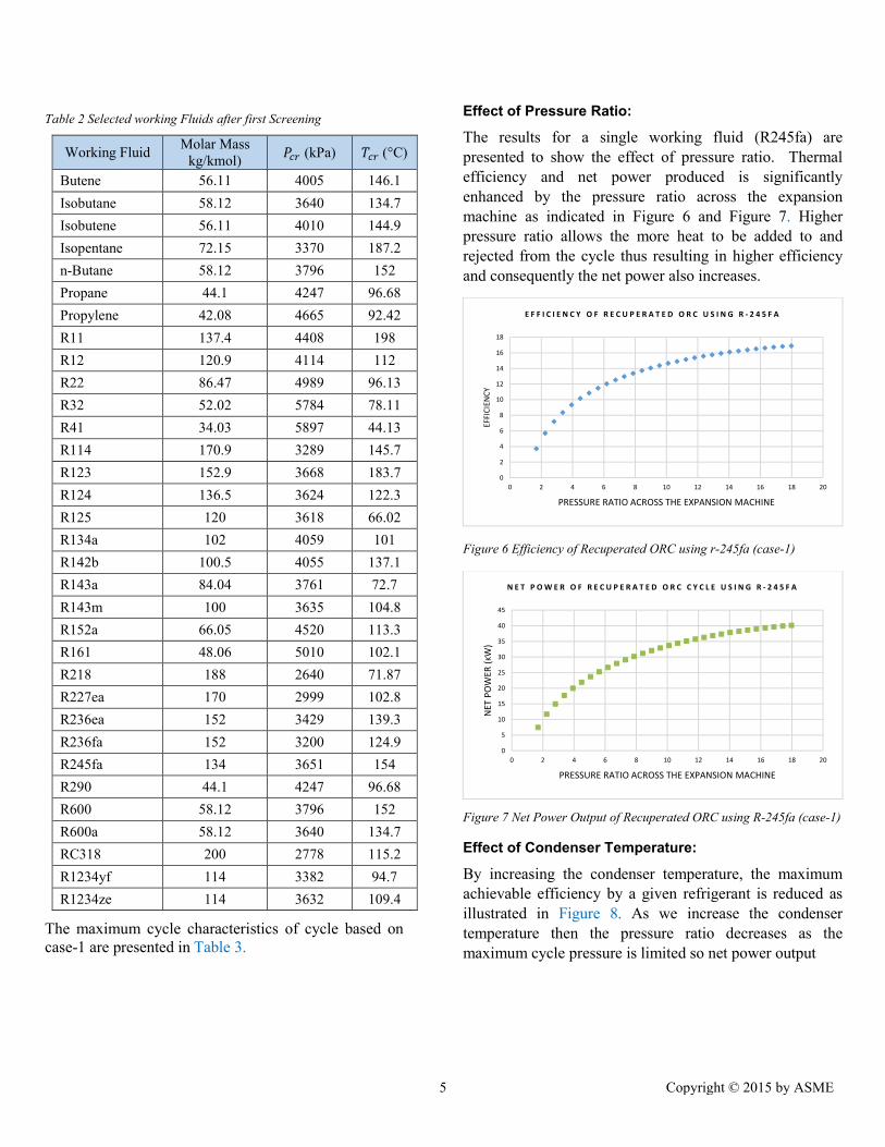
Table 2 Selected working Fluids after first Screening
Working Fluid Molar Mass
kg/kmol) ��� (kPa) ��� (°C)
Butene 56.11 4005 146.1
Isobutane 58.12 3640 134.7
Isobutene 56.11 4010 144.9
Isopentane 72.15 3370 187.2
n-Butane 58.12 3796 152
Propane 44.1 4247 96.68
Propylene 42.08 4665 92.42
R11 137.4 4408 198
R12 120.9 4114 112
R22 86.47 4989 96.13
R32 52.02 5784 78.11
R41 34.03 5897 44.13
R114 170.9 3289 145.7
R123 152.9 3668 183.7
R124 136.5 3624 122.3
R125 120 3618 66.02
R134a 102 4059 101
R142b 100.5 4055 137.1
R143a 84.04 3761 72.7
R143m 100 3635 104.8
R152a 66.05 4520 113.3
R161 48.06 5010 102.1
R218 188 2640 71.87
R227ea 170 2999 102.8
R236ea 152 3429 139.3
R236fa 152 3200 124.9
R245fa 134 3651 154
R290 44.1 4247 96.68
R600 58.12 3796 152
R600a 58.12 3640 134.7
RC318 200 2778 115.2
R1234yf 114 3382 94.7
R1234ze 114 3632 109.4
The maximum cycle characteristics of cycle based on case-1 are presented in Table 3.
Effect of Pressure Ratio:
The results for a single working fluid (R245fa) are presented to show the effect of pressure ratio. Thermal efficiency and net power produced is significantly enhanced by the pressure ratio across the expansion machine as indicated in Figure 6 and Figure 7. Higher pressure ratio allows the more heat to be added to and rejected from the cycle thus resulting in higher efficiency and consequently the net power also increases.
Figure 6 Efficiency of Recuperated ORC using r-245fa (case-1)
Figure 7 Net Power Output of Recuperated ORC using R-245fa (case-1)
Effect of Condenser Temperature:
By increasing the condenser temperature, the maximum achievable efficiency by a given refrigerant is reduced as illustrated in Figure 8. As we increase the condenser temperature then the pressure ratio decreases as the maximum cycle pressure is limited so net power output
0
2
4
6
8
10
12
14
16
18
0 2 4 6 8 10 12 14 16 18 20EF
FIC
IEN
CY
PRESSURE RATIO ACROSS THE EXPANSION MACHINE
E F F I C I E N C Y O F R E C U P E R A T E D O R C U S I N G R - 2 4 5 F A
0
5
10
15
20
25
30
35
40
45
0 2 4 6 8 10 12 14 16 18 20
NET
PO
WER
(KW
)
PRESSURE RATIO ACROSS THE EXPANSION MACHINE
N E T P O W E R O F R E C U P E R A T E D O R C C Y C L E U S I N G R - 2 4 5 F A
5 Copyright © 2015 by ASME
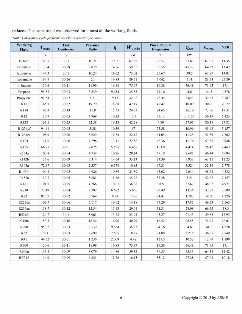
reduces. The same trend was observed for almost all the working fluids.
Table 3 Maximum cycle performance characteristics for case-1
Working Fluid
����� Tsat.
Condenser Pressure
Ratio � �̇����� Pinch Point at
Evaporator Q̇rec ����� VER
°C °C kW °C kW
Butene 143.5 30.1 10.21 15.5 67.38 26.53 27.67 67.05 14.35
Isobutane 133.4 30.09 8.079 14.86 59.35 36.55 45.33 64.32 11.42
Isobutene 144.3 30.1 10.24 16.62 73.02 25.67 39.5 67.87 14.01
Isopentane 164.9 30.26 20 19.83 89.61 5.042 104 83.43 25.89
n-Butane 150.6 30.11 11.99 16.88 75.97 19.38 56.48 71.95 17.1
Propane 95.82 30.03 3.539 9.654 35.83 74.16 4.6 44.5 4.378
Propylene 91.54 30.02 3.21 9.13 32.02 78.44 3.843 42.63 3.787
R11 165.3 30.22 19.79 18.68 42.17 4.642 10.09 81.6 20.72
R114 145.3 30.13 11.8 15.33 24.33 24.65 26.19 73.56 17.31
R12 110.9 30.05 4.968 10.23 15.7 59.13 0.1155 56.19 6.123
R123 165.1 30.25 22.58 19.23 42.28 4.89 27.05 80.38 27.81
R1234yf 94.41 30.05 3.88 10.39 17 75.58 10.96 45.43 5.157
R1234ze 108.9 30.06 5.629 11.54 22.12 61.05 11.25 51.39 7.562
R124 121.6 30.08 7.296 13.11 22.56 48.36 11.76 57.38 9.948
R125 66.21 30.01 2.075 5.591 6.458 103.8 4.474 28.42 2.462
R134a 100.8 30.04 4.734 10.26 20.14 69.18 2.681 46.44 6.004
R142b 136.6 30.09 9.314 14.64 35.13 33.39 9.953 63.11 12.25
R143a 72.67 30.03 2.357 6.578 10.83 97.31 3.524 32.34 2.778
R143m 104.4 30.05 4.926 10.89 21.89 65.62 7.614 48.74 6.532
R152a 112.7 30.05 5.881 11.86 35.28 57.28 3.21 52.67 7.157
R161 101.5 30.05 4.266 10.61 36.68 68.5 3.567 48.02 4.921
R218 72.49 30.04 2.382 6.682 5.635 97.49 13.36 33.27 3.209
R22 95.57 30.02 3.764 9.83 17.85 74.41 1.787 45.2 4.226
R227ea 102.7 30.06 5.117 10.92 14.18 67.29 17.85 49.53 7.563
R236ea 138.7 30.12 12.54 15.43 29.61 31.31 28.08 66.55 18.3
R236fa 124.7 30.1 8.961 13.73 23.94 45.27 21.43 59.83 12.93
r245fa 153.5 30.16 18.44 16.96 40.29 16.52 28.55 71.93 26.01
R290 95.82 30.03 3.539 9.654 35.83 74.16 4.6 44.5 4.378
R32 78.1 30.03 2.699 7.655 18.77 91.88 3.215 36.65 2.849
R41 44.52 30.01 1.236 2.009 4.48 125.5 10.53 13.99 1.198
R600 150.6 30.11 11.99 16.88 75.97 19.38 56.48 71.95 17.1
R600a 133.4 30.09 8.079 14.86 59.35 36.55 45.33 64.32 11.42
RC318 114.9 30.09 6.821 12.76 16.15 55.12 27.28 57.04 10.18
6 Copyright © 2015 by ASME
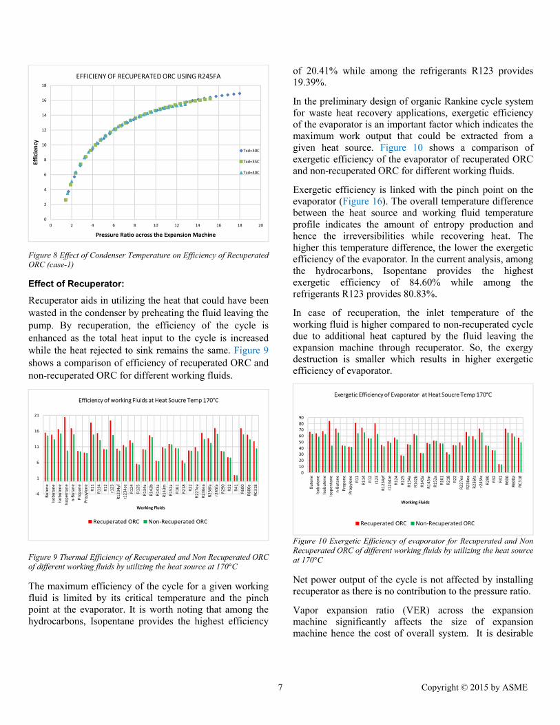
Figure 8 Effect of Condenser Temperature on Efficiency of Recuperated ORC (case-1)
Effect of Recuperator:
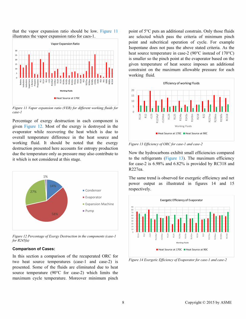
Recuperator aids in utilizing the heat that could have been wasted in the condenser by preheating the fluid leaving the pump. By recuperation, the efficiency of the cycle is enhanced as the total heat input to the cycle is increased while the heat rejected to sink remains the same. Figure 9 shows a comparison of efficiency of recuperated ORC and non-recuperated ORC for different working fluids.
Figure 9 Thermal Efficiency of Recuperated and Non Recuperated ORC of different working fluids by utilizing the heat source at 170°C
The maximum efficiency of the cycle for a given working fluid is limited by its critical temperature and the pinch point at the evaporator. It is worth noting that among the hydrocarbons, Isopentane provides the highest efficiency
of 20.41% while among the refrigerants R123 provides 19.39%.
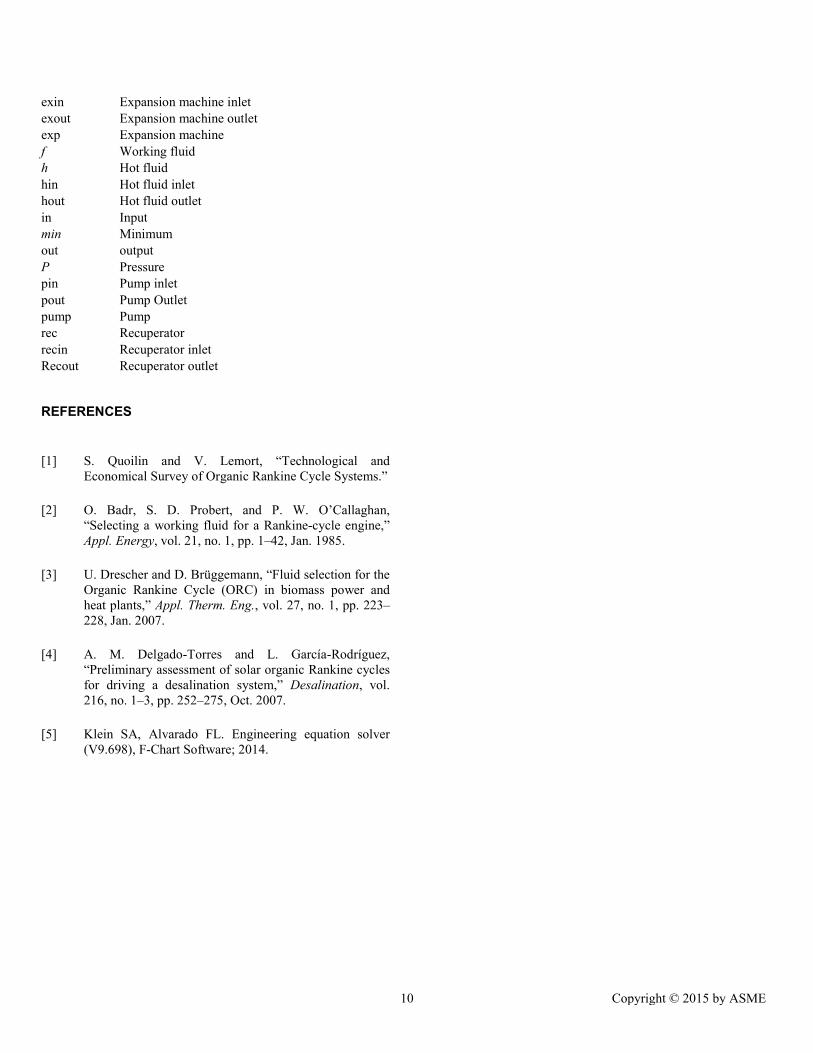
In the preliminary design of organic Rankine cycle system for waste heat recovery applications, exergetic efficiency of the evaporator is an important factor which indicates the maximum work output that could be extracted from a given heat source. Figure 10 shows a comparison of exergetic efficiency of the evaporator of recuperated ORC and non-recuperated ORC for different working fluids.
Exergetic efficiency is linked with the pinch point on the evaporator (Figure 16). The overall temperature difference between the heat source and working fluid temperature profile indicates the amount of entropy production and hence the irreversibilities while recovering heat. The higher this temperature difference, the lower the exergetic efficiency of the evaporator. In the current analysis, among the hydrocarbons, Isopentane provides the highest exergetic efficiency of 84.60% while among the refrigerants R123 provides 80.83%.
In case of recuperation, the inlet temperature of the working fluid is higher compared to non-recuperated cycle due to additional heat captured by the fluid leaving the expansion machine through recuperator. So, the exergy destruction is smaller which results in higher exergetic efficiency of evaporator.
Figure 10 Exergetic Efficiency of evaporator for Recuperated and Non Recuperated ORC of different working fluids by utilizing the heat source at 170°C
Net power output of the cycle is not affected by installing recuperator as there is no contribution to the pressure ratio.
Vapor expansion ratio (VER) across the expansion machine significantly affects the size of expansion machine hence the cost of overall system. It is desirable
0
2
4
6
8
10
12
14
16
18
0 2 4 6 8 10 12 14 16 18 20
Effi
cie
ncy
Pressure Ratio across the Expansion Machine
EFFICIENY OF RECUPERATED ORC USING R245FA
Tcd=30C
Tcd=35C
Tcd=40C
-4
1
6
11
16
21
Bu
ten
e
Iso
bu
tan
e
Iso
bu
ten
e
Iso
pen
tan
e
n-B
uta
ne
Pro
pan
e
Pro
pyl
ene
R1
1
R1
14
R1
2
r12
3
R1
234
yf
r12
34ze
R1
24
R1
25
R1
34a
R1
42b
R1
43a
R1
43m
R1
52a
R1
61
R2
18
R2
2
R2
27e
a
R2
36e
a
R2
36f
a
r24
5fa
R2
90
R3
2
R4
1
R6
00
R6
00a
RC
318
Working Fluids
Efficiency of working Fluids at Heat Soucre Temp 170°C
Recuperated ORC Non-Recuperated ORC
0
10
20
30
40
50
60
70
80
90
Bu
ten
e
Iso
bu
tan
e
Iso
bu
ten
e
Iso
pen
tan
e
n-B
uta
ne
Pro
pan
e
Pro
pyl
ene
R1
1
R1
14
R1
2
r12
3
R1
234
yf
r12
34ze
R1
24
R1
25
R1
34a
R1
42b
R1
43a
R1
43m
R1
52a
R1
61
R2
18
R2
2
R2
27e
a
R2
36e
a
R2
36f
a
r24
5fa
R2
90
R3
2
R4
1
R6
00
R6
00a
RC
318
Working Fluids
Exergetic Efficiency of Evaporator at Heat Soucre Temp 170°C
Recuperated ORC Non-Recuperated ORC
7 Copyright © 2015 by ASME
that the vapor expansion ratio should be low. Figure 11 illustrates the vapor expansion ratio for caes-1.
Figure 11 Vapor expansion ratio (VER) for different working fluids for case-1
Percentage of exergy destruction in each component is given Figure 12. Most of the exergy is destroyed in the evaporator while recovering the heat which is due to overall temperature difference in the heat source and working fluid. It should be noted that the exergy destruction presented here accounts for entropy production due the temperature only as pressure may also contribute to it which is not considered at this stage.
Figure 12 Percentage of Exergy Destruction in the components (case-1 for R245fa)
Comparison of Cases:
In this section a comparison of the recuperated ORC for two heat source temperatures (case-1 and case-2) is presented. Some of the fluids are eliminated due to heat source temperature (90°C for case-2) which limits the maximum cycle temperature. Moreover minimum pinch
point of 5°C puts an additional constrain. Only those fluids are selected which pass the criteria of minimum pinch point and subcritical operation of cycle. For example Isopentane does not pass the above stated criteria. As the heat source temperature in case-2 (90°C instead of 170°C) is smaller so the pinch point at the evaporator based on the given temperature of heat source imposes an additional constraint on the maximum allowable pressure for each working fluid.
Figure 13 Efficiency of ORC for case-1 and case-2
Now the hydrocarbons exhibit small efficiencies compared to the refrigerants (Figure 13). The maximum efficiency for case-2 is 6.98% and 6.82% is provided by RC318 and R227ea.
The same trend is observed for exergetic efficiency and net power output as illustrated in figures 14 and 15 respectively.
Figure 14 Exergetic Efficiency of Evaporator for case-1 and case-2
0
5
10
15
20
25
30
Bu
ten
e
Iso
bu
tan
e
Iso
bu
ten
e
Iso
pen
tan
e
n-B
uta
ne
Pro
pan
e
Pro
pyl
ene
R1
1
R1
14
R1
2
r12
3
R1
234
yf
r12
34ze
R1
24
R1
25
R1
34a
R1
42b
R1
43a
R1
43m
R1
52a
R1
61
R2
18
R2
2
R2
27e
a
R2
36e
a
R2
36f
a
r24
5fa
R2
90
R3
2
R4
1
R6
00
R6
00a
RC
318
Working Fluids
Vapor Expansion Ratio
Heat Source at 170C
14%
58%
27%
1%
Condenser
Evaporator
Expansion Machine
Pump
0
5
10
15
20
R1
14
R1
2
r12
3
R1
23
4yf
r12
34
ze
R1
24
R1
25
R1
34
a
R1
43
a
R1
43
m
R2
18
R2
2
R2
27
ea
R2
36
ea
R2
36
fa
RC
31
8
Working Fluids
Efficiency of working Fluids
Heat Source at 170C Heat Source at 90C
0
10
20
30
40
50
60
70
80
90
R1
14
R1
2
r12
3
R1
234
yf
r12
34ze
R1
24
R1
25
R1
34a
R1
43a
R1
43m
R2
18
R2
2
R2
27e
a
R2
36e
a
R2
36f
a
RC
318
Working Fluids
Exergetic Efficiency of Evaporator
Heat Source at 170C Heat Source at 90C
8 Copyright © 2015 by ASME

Figure 15 Net Power Output of ORC for case-1 and case-2
Figure 16 Pinch Point of ORC for case-1 and case-2
Conclusion
A computer program has been developed in engineering equation solver (EES) environment that analyzes and selects appropriate working fluid for organic Rankine cycle (subcritical operation) design based on available heat sources. For a given heat source, the program compares energy and exergy performance of various working fluids. The program also includes recuperator performance analysis and compares its effectiveness on the overall thermal performance of the Rankine cycle.
In this paper fluid characteristics, working of a computer program with two cases of heat source temperatures are studied and results presented. Based on the analysis the following points are concluded:
Efficiency of recuperated ORC is significantly improved by increasing pressure ratios across the expansion machine.
The critical temperature of fluid and pinch point based on heat source conditions limits maximum achievable efficiency and net power by a given refrigerant.
By using recuperator, thermal efficiency and exergetic efficiency of evaporator is improved while the net work done of the cycle is not affected.
Based on heat source (steam) at 170°C, Isopentane and R123 provide the highest exergetic and thermal efficiency of organic Rankine cycle.
Based on heat source (water) at 90°C, RC318 and R227ea provide the highest exergetic and thermal efficiency of organic Rankine cycle.
It should be noted that the final selection of working fluids is dependent on the user decision which may include environmental impacts, cost and economics of organic Rankine cycle system. The program can be further improved by incorporating the pressure drop analysis in the exchangers which is not considered at this stage.
NOMENCLATURE
C heat capacity rates (��.�
�)
D Increment in loop
e Flow exergy (J/kg) E Exergy (J/kg) h Specific enthalpy (J/kg)
�̇ Mass flow rate (kg/s)
�̇ Time rate of heat transfer (W)
s Specific entropy (J/kg.K) T Temperature (C)
VER Vapor expansion ratio
�̇ Time rate of work done (W)
y Increment in pressure
� Exergetic Efficiency
έ effectiveness
� Thermal Efficiency
ή Isentropic Efficiency
� Entropy Production
Subscript
amb ambient c Cold fluid
cd condenser cdin Condenser inlet cdout Condenser outlet
cin Cold fluid inlet cout Cold fluid outlet
cr Critical des Destruction evap Evaporator
evapin Evaporator inlet evapout Evaporator outlet
0
10
20
30
40
50
R1
14
R1
2
r12
3
R1
23
4yf
r12
34ze
R1
24
R1
25
R1
34
a
R1
43
a
R1
43
m
R2
18
R2
2
R2
27
ea
R2
36
ea
R2
36
fa
RC
31
8
Po
we
r (k
W)
Working Fluids
Net Power of Cycle
Heat Source at 170C Heat Source at 90C
0
20
40
60
80
100
120
R1
14
R1
2
r12
3
R1
23
4yf
r12
34ze
R1
24
R1
25
R1
34
a
R1
43
a
R1
43
m
R2
18
R2
2
R2
27
ea
R2
36
ea
R2
36
fa
RC
31
8
Working Fluids
Pinch Point at Evaporator of working Fluids
Heat Source at 170C Heat Source at 90C
9 Copyright © 2015 by ASME
exin Expansion machine inlet exout Expansion machine outlet exp Expansion machine
f Working fluid h Hot fluid
hin Hot fluid inlet hout Hot fluid outlet
in Input min Minimum out output
P Pressure pin Pump inlet
pout Pump Outlet pump Pump rec Recuperator
recin Recuperator inlet Recout Recuperator outlet
REFERENCES
[1] S. Quoilin and V. Lemort, “Technological and Economical Survey of Organic Rankine Cycle Systems.”
[2] O. Badr, S. D. Probert, and P. W. O’Callaghan, “Selecting a working fluid for a Rankine-cycle engine,” Appl. Energy, vol. 21, no. 1, pp. 1–42, Jan. 1985.
[3] U. Drescher and D. Brüggemann, “Fluid selection for the Organic Rankine Cycle (ORC) in biomass power and heat plants,” Appl. Therm. Eng., vol. 27, no. 1, pp. 223–228, Jan. 2007.
[4] A. M. Delgado-Torres and L. García-Rodríguez, “Preliminary assessment of solar organic Rankine cycles for driving a desalination system,” Desalination, vol. 216, no. 1–3, pp. 252–275, Oct. 2007.
[5] Klein SA, Alvarado FL. Engineering equation solver (V9.698), F-Chart Software; 2014.
10 Copyright © 2015 by ASME