A Computational Study of Axial Compressor Rotor Casing ...
124
Virginia Commonwealth University Virginia Commonwealth University VCU Scholars Compass VCU Scholars Compass Theses and Dissertations Graduate School 2006 A Computational Study of Axial Compressor Rotor Casing A Computational Study of Axial Compressor Rotor Casing Treatments and Stator Land Seals Treatments and Stator Land Seals Charles C. Cates Virginia Commonwealth University Follow this and additional works at: https://scholarscompass.vcu.edu/etd Part of the Engineering Commons © The Author Downloaded from Downloaded from https://scholarscompass.vcu.edu/etd/920 This Thesis is brought to you for free and open access by the Graduate School at VCU Scholars Compass. It has been accepted for inclusion in Theses and Dissertations by an authorized administrator of VCU Scholars Compass. For more information, please contact [email protected].
Transcript of A Computational Study of Axial Compressor Rotor Casing ...

Virginia Commonwealth University Virginia Commonwealth University
VCU Scholars Compass VCU Scholars Compass
Theses and Dissertations Graduate School
2006
A Computational Study of Axial Compressor Rotor Casing A Computational Study of Axial Compressor Rotor Casing
Treatments and Stator Land Seals Treatments and Stator Land Seals
Charles C. Cates Virginia Commonwealth University
Follow this and additional works at: https://scholarscompass.vcu.edu/etd
Part of the Engineering Commons
© The Author
Downloaded from Downloaded from https://scholarscompass.vcu.edu/etd/920
This Thesis is brought to you for free and open access by the Graduate School at VCU Scholars Compass. It has been accepted for inclusion in Theses and Dissertations by an authorized administrator of VCU Scholars Compass. For more information, please contact [email protected].


Table of Contents
LIST OF FIGURES .......................................................................................................... V
LIST OF TABLES ....................................................................................................... VIII
ABSTRACT ..................................................................................................................... IX
CHAPTER 1.INTRODUCTION ..................................................................................... 1
CHAPTER 2.BACKGROUND AND TERMINOLOGY .............................................. 4
2.1 AREAS OF INTEREST ................................................................................................ 4 2.1.1 Stator Labyrinth Seals ...................................................................................... 7 2.1.2 Compressor Rotor Casing Treatment .............................................................. 9
2.2 BACKGROUND AND CFD HISTORY ........................................................................ 13 2.3 COMPUTATIONAL RESOURCES ............................................................................... 16 2.4 LITERATURE SURVEY ............................................................................................ 17
2.4.1 Stator Seals ..................................................................................................... 17 2.4.2 Compressor Rotor Casing Treatments ........................................................... 23
CHAPTER 3.THEORY .................................................................................................. 28
3.1 GOVERNING EQUATIONS ....................................................................................... 28 3.2 ADPAC CFD CODE .............................................................................................. 32
3.2.1 ADPAC Solution Process .............................................................................. 33 3.2.2 ADPA C Procedure of Current Work .............................................................. 38
3.3 STATOR SEALS AND FLUENT BACKGROUND .......................................................... 45 3.3.1 Fluent Procedure of Current Work ................................................................ 46
........................ CHAPTER 4.COMPUTATIONAL RESULTS AND DISCUSSION 52
4.1 STATOR SEAL CAVITY INVESTIGATION .................................................................. 52 4.1.1 Stator One Geometry Results ......................................................................... 53 4.1.2 Stator Two Seal Cavity Results ................................................................... 61 4.1.3 Stator Seal Study Conclusions ........................................................................ 69
4.2 COMPRESSOR ROTOR CASING TREATMENT STUDY ........................................ 71 4.2.1 Circumferential Grooves Results ................................................................... 73 4.2.2 Compressor Rotor Casing Treatment Study Conclusions ............................. 96
CHAPTER 5.CONCLUSIONS ...................................................................................... 98

iv
LIST OF REFERENCES ............................................................................................. 103
APPENDIX A1 .............................................................................................................. 106
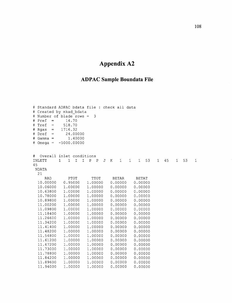
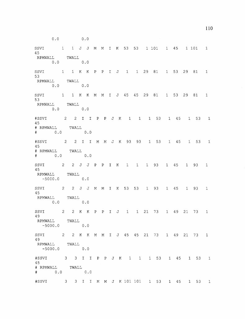
APPENDIX A2 .............................................................................................................. 108
VITA ............................................................................................................................... 114
List of Figures
Figure I: Cutaway of a 9-Stage Compressor with Detail of Stator-Rotor-Stator Stage with Stator Land
Seal, From Heidegger et. al. [27] 5
Figure 2: Solidfiame mock-up of Stator-Rotor-Stator stage with Circumferential Groove Rotor Endwall
Casing Treatment 7
Figure 3: Expanded view of stator labyrinth seals; rotating components in dark shading, non-rotating
components in light shading 8
Figure 4: Sample Compressor Map, Percent Corrected Speed Lines in Black, Compressor Eficiency
Islands in Blue 10
Figure 5: WireJi-ame Image of all Solid Surfaces in Stator-Rotor-Stator Stage; With Circumferential
Groove Casing Treatment Above Rotor 37
Figure 6: View of Full Modeled Flowpath with Solid Surfaces Highlighted 38
Figure 7: Zoomed in View of Rotor Endwall Casing Treatment and Rotor Blade Tip Gap 39
Figure 8: View From Above Rotor Passage; Blade Airfoil Profile in White, Case Mesh and Groove Mesh
Visible in Pink 40
Figure 9: Rotor Casing Treatment Mesh Showing Point-to-Point Correlation of Mesh 41
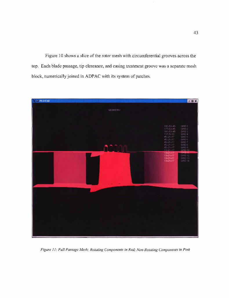
Figure 10: Rotor Hub, Blade, Endwall, and Casing Treatment Mesh with Stator Passages Outlined on
Either Side 42
Figure 11: Full Passage Mesh; Rotating Components in Red; Non-Rotating Components in Pink 43
Figure 12: Stator I Seal Area Detail With Measurement Stations 1-4 Labeled 48
Figure 13: Stator 1 Seal Tooth Gap Detail; Left: Baseling, O.OIOff; Top Right: 0.005"; Bottom Right:
0.01 5" 49
Figure 14: Stator 2 Detail with Measurement Stations Labeled 50

Figure 16: Stator 1 Cavity Reference Locations 56
Figure 21: Axisymmetrically Averaged Velocity Vectors; Top: Baseline, 0.01 0': Bottom Left: 0.005",
Bottom Right: 0.015" 61
Figure 22: Stator 2 Cavity Reference Locations 65
Figure 23: Stator 2 Static Pressure Throughout Cavity 65
Figure 24: Stator 2 Total Pressure Throughout Cavity 66
Figure 25: Stator 2 Tangential Velocity Throughout Cavity 66
Figure 26: Stator 2 Total Temperature Throughout Cavity 67
Figure 2 7: Axisymmetrically Averaged Velocity Vectors Through Stator 2 Seal Cavity; Left: 0.0 lbm/s
Through Center Seal, With Detail, Right: 0.32 lbm/s Through Center Seal 68
Figure 28: Baseline Untreated Rotor Convergence Plots 75
Figure 29: Rotor Mesh With Casing Treatment Convergence Plots 76
Figure 30: Eflciency and Pressure Ratio versus Compressor Inlet Corrected Flow 78
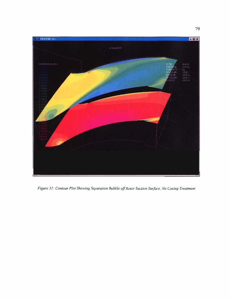
Figure 31: Contour Plot Showing Separation Bubble offRotor Suction Surface, No Casing Treatment - 79
Figure 32: Contour Plot Showing Separation Surface offRotor Suction Surface, With Casing Treatment 80
Figure 33: Streamlines From the Rotor Tip Colored by Velocity Magnitude, No Casing Treatment 81
Figure 34: Streamlines From the Rotor Tip Colored by Velocity Magnitude, With Casing Treatment - 82
Figure 35: Reverse Angle of Particle Traces Released From Rotor Tip Suction Side, No Casing Treatment
83
Figure 36: Reverse Angle of Particle Traces Released From Rotor Tip Suction Side, With Casing
Treatment 84
Figure 37: Flow in to and out of Grooves, Looking Axially Backwards From Suction Surface 88
Figure 38: Flow Injected in to and out of the First Groove 89
Figure 39: Flow Injected in to and out of the Second Groove 90
Figure 40: Flow Injected in to and out of the Third Groove 91
Figure 41: Flow Injected in to and out of the Fourth Groove 92
Figure 42: Flow Injected in to and out of the Fifth Groove 93
vii
Figure 43: Streamlines Showing Combination of Outflow From All Five Circumferential Grooves 94
Figure 44-48: Grooves 1-5 (Left to Right, Top to Bottom) Showing Structure of Flow Immediately Above
Rotor Blade 95

List of Tables
Table 1: Stator 1 Seal Cavity Mass Flow as a Percentage of Total Corrected Stator Mass Flow 54
Table 2: Stator 2 Cavity Mass Flow as a Percentage of Total Corrected Stator Mass Flow 62

Abstract
A COMPUTATIONAL STUDY OF AXIAL COMPRESSOR ROTOR CASING TREATMENTS AND STATOR LAND SEALS
By Charles C. Cates, M.S.M.E.
A thesis submitted in partial fulfillment of the requirements for the degree of Master of Science in Mechanical Engineering at Virginia Commonwealth University.
Virginia Commonwealth University, 2006
Major Director: James T. McLeskey, Jr., Ph.D. Department of Mechanical Engineering
As fuel prices soar ever higher, aircraft manufacturers and their airline customers
demand that the next generation of engines used on their aircraft push the limits of
efficiency and capability. This study consists of a computational examination of two
currently accepted methods of axial compressor performance improvement in terms of
surge margin and efficiency, rotor casing treatments and stator land seals.
ADPAC and Fluent CFD solvers were used in the analysis of circumferential
groove casing treatments and two types of stator seals, one typical of a fiont stage stator
and one typical of a rear stage stator. The computational solutions and visualizations
allowed for greater understanding of the complex flows inherent in each of these features.
It was found that rotor tip vortex control plays a large part in the surge margin gains from
a circumferential groove casing treatment. The efficiency gains of knife seals were
dependent primarily on the gap size of the seals.

Chapter 1.
1.1 Motivation
INTRODUCTION
With the recent introduction of high-efficiency airliners such as the Boeing 787
and the Airbus A380, greater pressure has been placed on engine manufacturers to
produce engines with both higher peak efficiency and higher peak performance. For
example, Boeing claims that when the 787 is first flown in 2007, it will use 15 to 20
percent less fuel on a per-passenger basis than other current products in the 200 to 250-
passenger range. They expect that approximately half of that fuel economy boost will
come from gains in engine efficiency alone [I]. Likewise, Airbus cites 13% lower fuel
burn than its closest competitor to the A380, with the fuel economy expected to be 95
miles per gallon per passenger. The A380 is also expected cany 35% more passengers at
a 15% lower seat cost per mile with the noise level at take-off only half that of its current
closest competitor [2].
Aircraft manufacturers and their airline customers want their aircraft to be able to
"fly higher, faster, farther, cleaner, quieter, and more efficiently" than ever before. All of
those qualifications relate directly to the performance of their gas turbine engines. To
design an engine with such demanding expectations requires outstanding predictive
1