A Comprehensive Review of Axial-Flux Permanent-Magnet Machines
15
CANADIAN JOURNAL OF ELECTRICAL AND COMPUTER ENGINEERING, VOL. 37, NO. 1, WINTER 2014 19 A Comprehensive Review of Axial-Flux Permanent-Magnet Machines Revue de littérature sur les machines à aimant permanent à flux axiale Solmaz Kahourzade, Student Member, IEEE, Amin Mahmoudi, Member, IEEE, Hew Wooi Ping, Member, IEEE, and Mohammad Nasir Uddin, Senior Member, IEEE Abstract—This paper presents a state-of-the-art review of axial-flux permanent-magnet (AFPM) machines in the aspects of construction, features, electromagnetic and thermal modeling, simulation, analysis, design, materials, and manufacturing. Some key references on the above-mentioned aspects pertaining to the machine are discussed briefly. Particular emphasis is given on the design and performance analysis of AFPM machines. A comparison among different permanent magnet machines is also provided. Thus, this paper makes a bridge between the currently used permanent magnet machines in industry and the recent developments of AFPM machines. Résumé—Cet article présente une revue sur l’état de l’art de la construction, caractéristiques, modélisation thermique et électromagnétique, simulation, analyse, conception et matériaux des machines à aimant permanent à flux axiale (APFA). Quelques références importantes portant sur les aspects mentionnés ci-dessus des machines sont abordées brièvement. La conception et l’analyse des performances des machines APFA sont présentées avec plus de détails. Une comparaison entre les différentes machines à aimant permanent est également présentée. Ainsi, ce papier est une jonction entre les machines à aimant permanent actuellement utilisés dans l’industrie et les développements récents des machines APFA. Index Terms—Axial-flux permanent-magnet machine (AFPM), cogging torque, design, field weakening, finite-element analysis, generator, motor, optimization. I. I NTRODUCTION T HE development of axial-flux permanent-magnet (AFPM) machines has been slow compared to that of conventional radial-flux permanent-magnet (RFPM) machines because of the lack of fabrication technology of AFPM machines. This limitation results from the strong axial magnetic attraction between the stator and rotor, which causes the deflection of rotor discs and fabrication difficulties such as lamination in the slotted stator, high cost, and assembly [1]. However, the higher torque-to-weight ratio due to the application of less core material, smaller size, planar and easily adjustable air gap, lower noise, and lower vibration make AFPM machines superior to RFPM machines [2]. Before Davenport claimed the first patent for the radial-flux Manuscript received October 21, 2013; revised January 7, 2014; accepted February 11, 2014. Date of current version May 6, 2014. This work was supported by the University of Malaya under the High Impact Research Grant D000022-16001 which funds the Hybrid Solar Energy Research Suitable for Rural Electrification. S. Kahourzade, A. Mahmoudi, and H. W. Ping are with the UM Power Energy Dedicated Advanced Centre, Wisma Research and Develop- ment UM, University of Malaya, Kuala Lumpur 59990, Malaysia (e-mail: [email protected]; [email protected]; wphew@ um.edu.my). M. N. Uddin is with the Department of Electrical Engineering, Lakehead University, Thunder Bay, ON P7B 5E1, Canada (e-mail: [email protected]). Associate Editor managing this paper’s review: S. R. Samantaray. Color versions of one or more of the figures in this paper are available online at http://ieeexplore.ieee.org. Digital Object Identifier 10.1109/CJECE.2014.2309322 machine in 1837 [3], the axial-flux machine was invented by Faraday in 1831 as the first electrical machine [4]. The AFPM machines have been widely used in numerous applications, from domestic to high-industrial and military applications, renewable energy systems to transportation, wherever extreme axial compactness coupled with high torque density and high efficiency are necessary. The AFPM machine topologies have been extensively investigated. However, despite the significant development in the AFPM machine technology, a gap still exists in industrial applications and some key aspects in the analysis and design of such machines published in recent papers. Therefore, this paper presents a comprehensive review on the analysis, design, and prototyping of AFPM machines. II. AFPM MACHINES TOPOLOGIES The AFPM machine structure includes surface mounted or interior PMs, with or without armature slots, with or without armature core, with ring winding or drum winding, and single- or multistage. Fig. 1 shows various topologies of AFPM machines. The AFPM machines are classified as single- stator single-rotor (SSSR), single-stator double-rotor (SSDR), double-stator single-rotor (DSSR), or multistator multirotor (MSMR). All mentioned design configurations are briefly described as follows. A. SSSR Machine The simplest structure of the AFPM machine is single-stator single-rotor (SSSR) [5]. Fig. 2 depicts an example of SSSR 0840-8688 © 2014 IEEE. Personal use is permitted, but republication/redistribution requires IEEE permission. See http://www.ieee.org/publications_standards/publications/rights/index.html for more information.
-
Upload
mohammad-nasir -
Category
Documents
-
view
212 -
download
0
Transcript of A Comprehensive Review of Axial-Flux Permanent-Magnet Machines

CANADIAN JOURNAL OF ELECTRICAL AND COMPUTER ENGINEERING, VOL. 37, NO. 1, WINTER 2014 19
A Comprehensive Review of Axial-FluxPermanent-Magnet Machines
Revue de littérature sur les machines àaimant permanent à flux axiale
Solmaz Kahourzade, Student Member, IEEE, Amin Mahmoudi, Member, IEEE,Hew Wooi Ping, Member, IEEE, and Mohammad Nasir Uddin, Senior Member, IEEE
Abstract— This paper presents a state-of-the-art review of axial-flux permanent-magnet (AFPM) machinesin the aspects of construction, features, electromagnetic and thermal modeling, simulation, analysis, design,materials, and manufacturing. Some key references on the above-mentioned aspects pertaining to the machineare discussed briefly. Particular emphasis is given on the design and performance analysis of AFPM machines.A comparison among different permanent magnet machines is also provided. Thus, this paper makes a bridgebetween the currently used permanent magnet machines in industry and the recent developments of AFPMmachines.
Résumé— Cet article présente une revue sur l’état de l’art de la construction, caractéristiques, modélisationthermique et électromagnétique, simulation, analyse, conception et matériaux des machines à aimantpermanent à flux axiale (APFA). Quelques références importantes portant sur les aspects mentionnésci-dessus des machines sont abordées brièvement. La conception et l’analyse des performances des machinesAPFA sont présentées avec plus de détails. Une comparaison entre les différentes machines à aimant permanentest également présentée. Ainsi, ce papier est une jonction entre les machines à aimant permanent actuellementutilisés dans l’industrie et les développements récents des machines APFA.
Index Terms— Axial-flux permanent-magnet machine (AFPM), cogging torque, design, field weakening,finite-element analysis, generator, motor, optimization.
I. INTRODUCTION
THE development of axial-flux permanent-magnet(AFPM) machines has been slow compared to that of
conventional radial-flux permanent-magnet (RFPM) machinesbecause of the lack of fabrication technology of AFPMmachines. This limitation results from the strong axialmagnetic attraction between the stator and rotor, whichcauses the deflection of rotor discs and fabrication difficultiessuch as lamination in the slotted stator, high cost, andassembly [1]. However, the higher torque-to-weight ratio dueto the application of less core material, smaller size, planarand easily adjustable air gap, lower noise, and lower vibrationmake AFPM machines superior to RFPM machines [2].Before Davenport claimed the first patent for the radial-flux
Manuscript received October 21, 2013; revised January 7, 2014; acceptedFebruary 11, 2014. Date of current version May 6, 2014. This work wassupported by the University of Malaya under the High Impact Research GrantD000022-16001 which funds the Hybrid Solar Energy Research Suitable forRural Electrification.
S. Kahourzade, A. Mahmoudi, and H. W. Ping are with the UMPower Energy Dedicated Advanced Centre, Wisma Research and Develop-ment UM, University of Malaya, Kuala Lumpur 59990, Malaysia (e-mail:[email protected]; [email protected]; [email protected]).
M. N. Uddin is with the Department of Electrical Engineering,Lakehead University, Thunder Bay, ON P7B 5E1, Canada (e-mail:[email protected]).
Associate Editor managing this paper’s review: S. R. Samantaray.Color versions of one or more of the figures in this paper are available
online at http://ieeexplore.ieee.org.Digital Object Identifier 10.1109/CJECE.2014.2309322
machine in 1837 [3], the axial-flux machine was invented byFaraday in 1831 as the first electrical machine [4]. The AFPMmachines have been widely used in numerous applications,from domestic to high-industrial and military applications,renewable energy systems to transportation, wherever extremeaxial compactness coupled with high torque density and highefficiency are necessary. The AFPM machine topologies havebeen extensively investigated. However, despite the significantdevelopment in the AFPM machine technology, a gap stillexists in industrial applications and some key aspects in theanalysis and design of such machines published in recentpapers. Therefore, this paper presents a comprehensive reviewon the analysis, design, and prototyping of AFPM machines.
II. AFPM MACHINES TOPOLOGIES
The AFPM machine structure includes surface mountedor interior PMs, with or without armature slots, with orwithout armature core, with ring winding or drum winding,and single- or multistage. Fig. 1 shows various topologies ofAFPM machines. The AFPM machines are classified as single-stator single-rotor (SSSR), single-stator double-rotor (SSDR),double-stator single-rotor (DSSR), or multistator multirotor(MSMR). All mentioned design configurations are brieflydescribed as follows.
A. SSSR Machine
The simplest structure of the AFPM machine is single-statorsingle-rotor (SSSR) [5]. Fig. 2 depicts an example of SSSR
0840-8688 © 2014 IEEE. Personal use is permitted, but republication/redistribution requires IEEE permission.See http://www.ieee.org/publications_standards/publications/rights/index.html for more information.

20 CANADIAN JOURNAL OF ELECTRICAL AND COMPUTER ENGINEERING, VOL. 37, NO. 1, WINTER 2014
Fig. 1. Various topologies of AFPM machines.
Fig. 2. 3-D view of a four-pole-pair/12-slot SSSR AFPM machine.
AFPM machine. It is a 3-D diagram of the 12 slots, four polepairs SSSR AFPM machine with concentrated winding knownas nonoverlapping windings. However, distributed winding isalso applicable. The SSSR AFPM machines have applicationsin industrial traction, servo electromechanical drives, military,transportation industries, and gearless elevators because ofits compact structure and high torque capability [6]. Themajor disadvantage of this machine is the imbalanced axialforce between stator and rotor, which may twist the structureeasily [7]. Different methods have been presented to achievethe maximum rotational torque with minimized axial force.Some of these methods are: adjusting the portions of statorwinding currents projected onto the orthogonal sets of axescorresponding to the rotor positions, slotless stator, complexbearing arrangements, thicker rotor disc, and current shiftingangle [8].
B. DSSR Machine
In two-stator one-rotor axial-flux interior-rotor machine, therotor is either located between two slotted stators (SS-type) ortwo slotless stators (NS-type), whereas PMs are located onthe surface of the rotor disc or inside the rotor disc [9]. Fig. 3shows the 3-D diagram of the slotted double-stator single-rotor(DSSR) AFPM machine. This figure is a 3-D configuration ofthe motor with concentrated winding.
Fig. 4(a) and (b) shows the flux paths for the surface-mounted and interior DSSR AFPM structure, respectively.Main flux flows circumferentially along the rotor disc oraxially through the rotor disc. Power density in the interior
Fig. 3. 3-D view of a four-pole-pair/12-slot DSSR AFPM machine.
PM structure is lower than that in the surface-mounted struc-ture because of the requirement for a thicker rotor disc.
Leakage flux of PM ends and armature reaction in interiordesign are higher compared with that of the surface-mounteddesign because PMs are surrounded by ferromagnetic material.However, the buried PM structure better protects PMs againstmechanical impact, wear, and corrosion [10].
In another DSSR AFPM structure, the steel rotor disc iseliminated based on the main flux path [11]. Fig. 4(c) showsthat the main flux does not travel through the rotor. In thisstructure, a nonmagnetic material such as aluminum is used tofill the spaces between the PMs and construct a rigid structure.This process generates high power to inertia ratio because ofthe lack of iron in the rotor, which makes this structure suitablefor small inertia applications.
The copper loss in DSSR AFPM machines is high becauseof the long end windings. Whereas, slotted stator constructionshows lower copper loss and consequently higher efficiencycompared with the slotless structure [12]. A nonmagneticmaterial such epoxy resin is applied to fill the spaces of statorwindings to improve the robustness and heat transfer in allslotless structures [13].
C. SSDR Machine
In single-stator double-rotor (SSDR) AFPM machines, theslotted or slotless stator is located between two rotors [14].Fig. 5 shows an example of a typical SSDR machine. Thisfigure is a 3-D configuration of the motor with concentratedwinding (the same as Fig. 2 which is simply double sided).

KAHOURZADE et al.: COMPREHENSIVE REVIEW OF AFPM MACHINES 21
Fig. 4. Flux paths in 2-D plane for DSSR structure of the AFPM machine. (a) Surface-mounted PM structure. (b) Buried PM structure. (c) InteriorPM structure without steel disc.
Fig. 5. 3-D view of a four-pole-pair/12-slot SSDR AFPM machine.
Fig. 6. Flux paths in 2-D plane for SSDR AFPM machine. (a) NN PMstructure. (b) NS PM structure.
In SSDR topology, the main flux either travels axiallythrough the stator or circumferentially in the stator yokewhile the torque is generated by the radial direction wind-ings [15]. In slotless machines, end windings are short, suchthat less copper loss and better heat dissipation are achieved.Leakage and mutual inductance in a slotless configurationare also lower. Therefore, slot effects such as flux ripple,cogging torque, high-frequency rotor loss, and stator teeth areeliminated [16]. Flux direction of the slotted SSDR AFPMmachine with NN and NS PM arrangements are presented inFig. 6(a) and (b), respectively.
Fig. 7. Coreless NS TORUS structure of the AFPM machine.
These structures have different stator-yoke thicknesses andwinding arrangements. In NN structure, the wound phasewinding around the stator core (ring windings) in both theaxial and radial directions is short. As a result, a thick statoryoke is necessary for the total flux entering the stator fromboth rotors, which enhances the iron loss and lengthens endwindings. In NS structure, main flux travels axially through thestator, which makes the stator yoke unnecessary. In this case,iron loss is reduced. However, drum windings are required forNS configuration which lengthen end windings and increasethe external diameter of machine to produce torque [17].
Another SSDR machine is the coreless AFPM machine(Fig. 7) [18]. In this machine, main flux travels from onerotor to another rather than passing circumferentially alongthe stator core. The stator and rotor include only windingsand surface PMs, respectively. The efficiency could be veryhigh with the application of strong PMs due to the absence ofiron loss [19]. This structure is mainly preferred in applicationsthat less cogging torque and torque ripple are tolerated.
D. MSMR Machine
A multistage AFPM machine can be constructed from eitherDSSR or SSDR configurations [20]. This machine includesthe N stators and N + 1 rotors that have the same mechanicalshaft. The stator windings can be connected either in parallelor in series. The multistage configuration enhances the torqueand power density without increasing the machine diameter.Among multistage AFPM and RFPM machines, AFPM onescan be more easily assembled because of their planar air-gap.
The MSMR AFPM machines may include slotted or slot-less, iron core or ironless, NN or NS topologies while

22 CANADIAN JOURNAL OF ELECTRICAL AND COMPUTER ENGINEERING, VOL. 37, NO. 1, WINTER 2014
Fig. 8. 3-D view of a four-pole-pair/12-slot multistage AFPM machine(N = 2 stator; N + 1 = 3 rotors).
their flux paths are the same as their single-stage structures.The advantages and disadvantages of each construction aresimilar to their relevant preceding structures. The multistageAFPM machines have applications in ship propulsions, pumps,and high-speed PM generators [21]. Fig. 8 shows a 3-Ddiagram of a multistage AFPM machine.
III. AFPM MACHINE DESIGN AND SIZING EQUATION
A. Sizing Equation
The initial step in AFPM machine design is the selectionof suitable volume of PMs, dimensions of stators, and rotorsbased on various constraints such as rated/maximum torque,rated/maximum speed, maximum allowable geometric dimen-sions, cooling method, maximum line-to-line voltage, phasecurrent, etc. Sizing equation is proposed to determine theconstruction and dimensions of the AFPM motor includingnumber of phases, stator slots, PM volume, outer and innerdiameter of the stator and rotor, and air-gap length [22], [23].If the resistance and leakage inductance of the stator arenegligible, the output power of the electrical machine iscalculated as
Pout = ηm
T
T∫
0
e(t) i(t)dt = ηmK p Epk Ipk (1)
where i(t) is the phase current, m is the number of machinephases, e(t) is the phase air-gap EMF, η is machine efficiency,K p is the electrical power waveform factor, T is the periodof one EMF cycle, and Epk and Ipk are the peaks of phaseair-gap EMF and of current, respectively [24]. K p and Epkare defined as
K p =T∫
0
e(t) · i(t)
Epk · Ipkdt (2)
Epk = Ke Nph Bgf
p
(1 − λ2) D2
o (3)
where Ke is the EMF factor incorporating winding distributionfactor and per-unit portion of air-gap area total spanned bysalient poles of the machine (if any), Nph is the number ofwinding turns per phase, Bg is the flux density in air-gap,f is the converter frequency, p is the machine pole pairs,λ is the diameter ratio Di/Do of the AFPM machine,Do is the diameter of outer surface of the machine, and Di is
the diameter of the inner surface of the machine. A general-purpose sizing equation for AFPM machines takes the follow-ing form [24]:
Pout = 1
1 + Kφ
m
m1
π
2Ke Ki K p KLηBg A
× f
p(1 − λ2)
(1 + λ
2
)D2
o Le (4)
where m1 is the number of phases of each stator, Le is theeffective axial length of the motor, Kφ is the electrical loadingratio on the rotor and stator, Ki is the current waveform factor(the ratio between the peak value and the rms value), and KL isthe aspect ratio coefficient pertinent to a specific machinestructure, considering effects of loss, temperature rise, andthe efficiency requirements of the design. The diameter ratioλ is the most important design parameter and has a significanteffect on machine characteristics. The value of λ must becarefully chosen to optimize machine performance. Machinepower density for total volume is defined as
pden = Poutπ4 D2
tot L tot(5)
where Dtot and L tot are the total outer diameter and total lengthof the machine, respectively, including the outer diameter andend winding protrusion of the stack from the radial and axialiron stacks.
B. Design Optimization
A general optimization process for an AFPM machine ispossible with shape modification through the choice of geo-metrical parameters, deterministic methods, or soft computingmethods [25]–[32]. Aydin et al. [25] developed optimum-sized AFPM machines for both SSDR and DSSR topologies,but only two parameters (diameter ratio and air-gap fluxdensity) are considered as optimization variables, and theoptimization was conducted through the shape modification. Inall shape-modification methods, there are tradeoffs among theperformance parameters, and the methods are not applicableto the multiobjective optimization problems. In some studies,the optimized value of 1/
√3 ≈ 0.58 for the ratio (λ) of inner
diameter to the outer diameter was chosen to maximize theoutput power in AFPM machines [26].
Yang et al. [27] presented an optimal design of an AFPMmachine using sensitivity analysis and a magnetic circuitmodel. The preliminary motor shapes were obtained by opti-mizing the cost function. Finite element analysis (FEA) wasperformed on the electromagnetic, thermal, and dynamicalcharacteristics. The considered objectives include the outputtorque, efficiency, and torque density. Hwang et al. [28]presented an optimum design of a coreless SSDR AFPMmachine using Taguchi method. The analysis and simulationswere conducted by FEA. Taguchi’s parameter design methodprovides a systematic approach to conduct the numericalexperiments to determine near optimum settings of the designparameters. The only studied objectives include minimizationof the ratio between torque ripple and average torque.

KAHOURZADE et al.: COMPREHENSIVE REVIEW OF AFPM MACHINES 23
Fig. 9. Flowchart for GA-based design optimization of AFPM machine.
Soft computing methods are proposed as a solution formultiobjective optimization problems because of highly effec-tive computer systems and novel, fast-computing algorithms.Standard optimization techniques include the random searchmethod, Hook and Jeeves method, Powell method, and geneticalgorithm (GA) [28]. The random search method requires along time to converge and depends entirely on the startingpoint, whereas the Hook and Jeeves method is slower butmore accurate [29]. The Powell method rapidly achieves anoptimal solution but is not as robust when faced with morecomplex problems or if the desired global minimum is hiddenamong several local minimums. Rostami et al. [30] reported anoptimized design of a variable-speed AFPM synchronous gen-erator. 3-D FEA is conducted to simulate the GA results withthe objective of minimizing the active cost while limited sim-ulation results are presented. Mahmoudi et al. [31] conductedGA-based sizing equation with performance analysis via FEAto optimize a 1 kW, 3-phase, 50 Hz, four-pole AFPM synchro-nous motor based on the practical limitations for a typicalscooter. The considered design objectives include maximumpower density, cogging torque minimization, and minimumTHD of the induced EMF. Fig. 9 shows the flowchart of ageneralized optimization of the AFPM motor using GA.
Kahourzade et al. [32] presented the optimized design of a1 kW, three-phase, 50 Hz, four-pole SSDR AFPM machine.The GA is used to optimize the dimensions of the machineto achieve the highest power density. Electromagnetic fieldanalysis of the candidate machines from GA with variousdimensions is then put through FEA to obtain various motorcharacteristics. With the results from GA and FEA, newcandidates are introduced and then put through (finite volume
analysis) FVA for thermal behavior evaluation of the designedmotors. Techniques like modifying the winding configurationand skewing the permanent magnets are also investigated toattain the most sinusoidal back-EMF waveform and reducedcogging torque. The performance of the designed machineis tested in simulation using FEA software. It is found thatthe simulation results agree with the designed technical spec-ifications. It is also found from FVA results that the motortemperature reaches at highest temperature to 87 °C at therated speed and full load under steady-state condition.
IV. ANALYSIS OF AFPM MACHINE
A. Electromagnetic Analysis
The electromagnetic field of AFPM machine is calculatedusing the analytical model, quasi 3-D analytical model, methodof image, 2-D finite element method (FEM), and 3-D FEM[33]–[37]. Needleless to say, 3-D FEM is more accurate ascompared to the analytical method and 2-D FEM. It is capa-ble of solving complicated problems with integral or partialdifferential equations. However, FEM is time consuming andrequires large memory capacity. To overcome these problems,some researchers have been conducted in electromagneticanalysis of AFPM machines using analytical models, whichachieve acceptable results similar to FEM.
Sung et al. [33] proposed the electromagnetic field analysisof an SSDR AFPM generator using improved quasi-3-Dand Maxwell’s equations. An analytical approach to analyzethe magnetic field distribution and estimate the equivalentcircuit parameters are presented that dramatically reduces theanalysis time while maintaining high reliability. The designedgenerator has slotless stator core for cogging torque reductionand ring-wound type coils that are placed in the stator core.The flux leakage was considered because it is dominant in theinner and outer radii of this type of machine. The experimentaltests verify all of the analysis results.
Lee et al. [34] proposed method of image using magneticcharge to analyze characteristics of the slotless AFPM motors.The method of image replaces the effects of a boundary onan applied field by simple distributions of current or chargesbehind the boundary line. The desired field is achieved by thesum of applied and image fields. Method of image is requiredfor the field on each side of a boundary, but the knowledgeof one group of images leads to the other, since the solutionsfor the two regions are connected by the boundary conditions.Mechanical stability is enhanced by the reduction of normalforce affects vibration and noise. Comparison between cal-culated and experimental results indicates some deviations.For instance, approximately 8% error at the peak value ofback-EMF due to saturation in magnetic circuits.
Chan et al. [35] proposed an analytical mean radius modelfor an ironless single-sided AFPM synchronous generator.Laplace equations are solved in the rectangular coordinate sys-tem to calculate the scalar magnetic potentials using a Fourierseries method. A multicurrent-sheet model is conducted tocalculate the armature reaction field, considering distributedarmature conductors. To verify the accuracy of the analyticalresults, the magnetic field was also computed using 2-D FEM.
24 CANADIAN JOURNAL OF ELECTRICAL AND COMPUTER ENGINEERING, VOL. 37, NO. 1, WINTER 2014
The analytical results give slightly higher field values, but,in general, the errors are within 3% of the computed resultsfrom FEM.
Huang et al. [36] presented a magnetic field analysisof an ironless AFPM machine under open-circuit conditionusing 3-D analytical modeling based on the magnetic scalarpotential and the cylindrical coordinate. The method involvesthe analytical solution of the governing field equations inthe region between back-irons in the cylindrical coordinate.In this region, the PMs are assumed to be axially magnetizedand have constant relative recoil permeability. The analyticalresults were concluded to be in good agreement with those of3-D FEA.
De la Barriere et al. [37] presented a 3-D analytical model ofan AFPM synchronous machine based on Maxwell equations.The analytical solution of the Laplace equation gives the scalarmagnetic potential in cylindrical coordinates. Fourier Besselseries have been introduced for taking into account the radialedge effects of the machine. Another original point is then useof a modulation function for considering the iron parts edgeeffects. The model is validated by 3-D FEM computations, fora computation time 95% lower than FEM. The electromagneticmodel should be improved for taking into account the machinesaliency in three dimensions, which remains as a challengingbut necessary task.
B. Cogging Torque Analysis
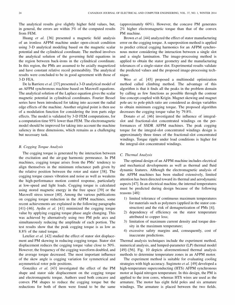
The cogging torque is generated by the interaction betweenthe excitation and the air-gap harmonic permeance. In PMmachines, cogging torque arises from the PMs’ tendency toalign themselves in the minimum reluctance path given bythe relative position between the rotor and stator [38]. Thecogging torque causes vibration and noise as well as weakensthe high-performance motion control response, particularlyat low-speed and light loads. Cogging torque is calculatedusing stored magnetic energy in the free space [39] or theMaxwell stress tensor [40]. Among the various publicationson cogging torque reduction in the AFPM machines, somerecent achievements are explained in the following paragraphs[41]–[46]. Aydin et al. [41] minimized the cogging torquevalue by applying cogging torque phase angle changing. Thiswas achieved by alternatively using two PM pole arcs andsimultaneously reducing the amplitude of each portion. Thetest results show that the peak cogging torque is as low as8.8% of the rated torque.
Letelier et al. [42] studied the effect of stator slot displace-ment and PM skewing in reducing cogging torque. Stator slotdisplacement reduces the cogging torque value close to 50%.However, the frequency of the cogging waveform doubled, andthe average torque decreased. The most important influenceof the skew angle is cogging variation for symmetrical andasymmetrical rotor pole positions.
González et al. [43] investigated the effect of the PMshape and stator side displacement on the cogging torqueand electromagnetic torque. Authors used both concave andconvex PM shapes to reduce the cogging torque but thereductions for both of them were found to be the same
(approximately 60%). However, the concave PM generates2% higher electromagnetic torque than that of the convexPM machine.
Brown et al. [44] analyzed the effect of stator manufacturingerror on the cogging torque. A superposition method is appliedto predict critical cogging harmonics for an AFPM synchro-nous motor considering the interaction between a single slotand a single lamination. The image-processing method isapplied to obtain the stator geometry and the manufacturingtolerances of a single-stator slot. Experimental results validatethe predicted values and the proposed image-processing tech-nique.
Woo et al. [45] proposed a multimodal optimizationmethod called climbing method. The advantage of thisalgorithm is that it finds all the peaks in the problem domainby calling as few functions as possible through the contourline concept coupled with Krigin. Magnet skewing and magnetpole-arc to pole-pitch ratio are considered as design variablesto obtain minimum cogging torque. The proposed algorithmdecreases the cogging torque value by 79.8%.
Donato et al. [46] investigated the influence of integral-slot and fractional-slot concentrated windings on the per-formances of SSDR AFPM machines. The peak coggingtorque for the integral-slot concentrated windings design isapproximately three times of the fractional-slot concentratedwindings. Torque ripple under load conditions is higher forthe integral-slot concentrated windings.
C. Thermal Analysis
The optimal design of an AFPM machine includes electricaland mechanical developments as well as thermal and fluiddynamic features. Although the electromagnetic analysis ofthe AFPM machines has been studied extensively, limitedattention has been directed toward its thermal and aerodynamicaspects [47]. In an electrical machine, the internal temperaturesmust be predicted during design because of the followingreasons [48]:
1) limited tolerance of continuous maximum temperaturesfor materials such as polymers (applied in the stator con-struction) and the risk of demagnetization of PMs [4];
2) dependency of efficiency on the stator temperatureattributed to copper loss;
3) limitation of maximum current density and torque den-sity in the maximum temperature;
4) excessive safety margins and, consequently, cost ofinaccurate predictions.
Thermal analysis techniques include the experiment method,numerical analysis, and lumped-parameter (LP) thermal model[49]–[56]. Fig. 10 depicts aforementioned thermal analysismethods to determine temperature zones in an AFPM motor.
The experiment method is suitable for evaluating coolingstrategies with high accuracy. Sugimoto et al. [49] developed ahigh-temperature superconducting (HTS) AFPM synchronousmotor at liquid nitrogen temperature. In this design, the PM isapplied to the iron cores, whereas HTS wires are used as thearmature. The motor has eight field poles and six armaturewindings. The armature is placed between the two fields.

KAHOURZADE et al.: COMPREHENSIVE REVIEW OF AFPM MACHINES 25
Fig. 10. Thermal analysis of an AFPM motor: experiment, lumped-parameter thermal model, and numerical analysis. (a) Infrared image of an AFPMtest-machine, for determination of temperature field [55]. (b) Temperature modeling of stator surface [56]. (c) Temperature (°K) contour for both rotor andstator of the motor representing the thermal distribution [32].
The BSCCO wires, which are applied to armature windings,work at temperatures between 66 and 70 K. However, super-conducting wires exhibit AC losses if they are operated atalternating magnetic fields.
The numerical methods, which are usually FEA-based orFVA-based, calculate generated losses in various regions,which act as the heat sources in the thermal analysis. Recently,the diffusion of commercial software packages that enablecoupled computational fluid dynamic (CFD) and FEA havegiven researchers a powerful tool to perform complex simu-lations of 3-D heat generation, flow, and exchange in AFPMmachines [50].
Marignetti et al. [51] studied the thermal characteristicsof an AFPM synchronous machine with a soft magneticcompound (SMC) core using 3-D-FEA. The thermal sourceis achieved from a dc current flow model coupled to themagneto static solver, thermal, and fluid-dynamical model. Thedisadvantage of the method is that the results are very sensi-tive to possible inaccuracy, thus affecting boundary conditionplacement. In addition, the rotor core of the prototype model issignificantly hotter than the simulation results. The operationaltemperature under the 403 °K is required by the epoxy.
Howey et al. [52], studied stator convective heat transfer byusing CFD modeling. A thin-film electrical heating methodprovides radially resolved steady-state heat-transfer data froman experimental rotor-stator system designed as a geometricmodel of a through-flow ventilated AFPM machine. Experi-mental results confirm that the predicted stator heat transferis almost insensitive to the turbulence model used in theCFD simulations.
The LP model depicts thermal problems through a ther-mal network similar to an electrical circuit. Lim et al. [53]proposed an LP model for a six-pole slotless SSDR AFPM
generator based on a simplified axisymmetric model. Thecomponents of the generator and the internal air-flow domainare split into a system of connected and interacting controlvolumes. To determine the thermal condition, energy andmass conservation equations are solved for each volume whileconsidering the heat transfer attributed to conduction andconvection. The accuracy of results is verified by comparingwith CFD results.
Rostami et al. [54] presented an LP model for solving thesteady-state thermal problem of a DSSR AFPM generator.The model derives the temperatures in the stator windingsand PMs. The LP model is derived from purely dimensionaldata and the material properties of the machine components.Iterative coupled electromagnetic and thermal designs areapplied because of the material temperature-dependent ther-mal properties. Experimental results of the designed machineverify the accuracy of the thermal resistance network in termsof predicting the nodal temperatures.
D. Mechanical Analysis and Manufacturing
Mechanical analysis has an important function in the designof an AFPM machine considering the effect of machinedimensions on its transient and steady-state performances,such as the dependency of centrifugal force on the PM lengthsor axial attractive forces on the air-gap length [57]–[63]. In thissection, articles on the structure and mechanical analysis ofAFPM machines are reviewed.
Liu et al. [57] proposed an algorithm for linear torquecontrol and axial force reduction of an AFPM motor appliedin an electric vehicle by determining a partial derivative of theco-energy of the machine with respect to the axial direction.The axial force is a nonlinear function of the stator MMF,

26 CANADIAN JOURNAL OF ELECTRICAL AND COMPUTER ENGINEERING, VOL. 37, NO. 1, WINTER 2014
Fig. 11. Sectional view of the rotor of the high-speed modular air-coredAFPM generator.
PM flux, and demagnetizing d-axis current component. Theproposed single-sided AFPM motor shows full operationalcontrollability using current shifting angle method. Optimaloperational performance is achieved using a current shiftingangle of (−30°) degrees.
Vansompel et al. [58] presented the efficiency optimizationof an AFPM synchronous generator with concentrated polewinding. A 3.6-kW 2000-r/min eight-pole pair AFPM gener-ator for combined heat and power applications is prototypedand tested. To reduce losses, concentrated pole windings, andsegmented PMs, a thin grain-oriented material for stator teethare applied in the design. The FEM and the analytical methodsare applied to study the effect of mass on the optimal values ofparameters and on efficiency. The flat course near the point ofmaximum efficiency in the mass-efficiency curve shows that adrastic reduction in mass results in slight efficiency reduction,which has an essential impact on the cost and portability ofthe machine.
Fei et al. [59] presented a mechanical design of a high-speed modular air-cored AFPM generator with focus on elec-tromagnetic optimization. Fig. 11 shows the designed rotor,which includes the PMs, retainment ring, and back iron. Arigid, high-strength rotor hub connects the PM rotor discand shaft. The rotor hub is shrunk to fit at the bore of themagnet rotor disc to prevent slippage of the magnet rotor athigh operating speed and is coupled with other rotor hubson the same shaft through mechanical splines. It is reportedthat during the acceleration of the rotor to the maximumspeed, slight vibrations of the rotor were observed at 22 300and 39 000 r/min, which is related to the different naturalfrequencies caused by the combinations of different rotor parts.Apart from these two speeds, the rotor runs smoothly withoutexperiencing any noticeable vibration.
Di Gerlando et al. [60] designed and tested a 50 kW,70 r/min, 19-pole pair, multistage AFPM direct-drive windgenerator with concentrated windings. The paper focused onthe sizing relations and electrical parameters. The machinestructure implies some peculiar features: the absence of statoryokes, compactness, low rotor inertia, and low synchronousinductance. Eddy current loss is decreased by using segmentedPMs because of the slotting and distributed mmf in the air gap.A strategy to reduce the free design parameters, to perform a
simple parametric analysis, and to achieve an optimized designis proposed. However, extra teeth core losses happened due tothe manufacturing process.
Lee et al. [61] compared the electromagnetic and mechan-ical performance of slotless AFPM machines with spiral andlaminated stator. The laminated stator is found to be stifferand simpler for manufacturing compared with those of thespiral stator. However, the laminated stator facilitates highertemperature at the magnetic core because of the increasingeddy current. The spiral stator demands higher phase currentat low speed because of the increasing magnetic air-gap fluxdensity under the same stator volume and generates more noisebecause of the lower stiffness of the stator.
De Donato et al. [62], [63] analyzed the effect of magneticSMC wedges on the load performance of AFPM machines.A reduction in reluctance of the slot leakage path usingSMC wedges enhances slot leakage inductance and shiftsno-load loss significantly from the PMs to the stator. Itfacilitates the extraction of generated heat and reducingthe danger of magnet demagnetization attributed to hightemperature.
V. FIELD CONTROL OF AFPM MACHINES
The absence of excitation windings and brush contactreduce the operational cost and increase the efficiency and reli-ability of AFPM machines. However, the fixed flux imposedby the PMs is crucial for variable speed applications. Thelinear variation of the induced back-EMF voltage makesthe operation dangerous at high speed. In fact, the windinginsulation and inverter power semiconductor can be degradedwhen operated at high voltage. To avoid this unsafe operation,air-gap flux must be controlled to keep the terminal voltageat rated value. Flux weakening in brushless AFPM machineseither is applied by mechanical means [64]–[66] or by con-trol strategies [67]–[71]. Some key publications on the fieldweakening of AFPM motors are reviewed in the followingparagraphs.
Del Ferraro et al. [64] proposed the mechanical flux weak-ening of AFPM machines by displacing two rotor discs toachieve a reduction in the stator linked flux. Desired reg-ulation is achieved by two different mechanical solutions:mechanical speed-dependent device and mechanical torque-dependent device. The first device is a constant voltage sourcewhere the second one is a constant current source. Althoughtheir work introduces an innovative concept of mechanicalflux weakening for AFPM power regulation in a wide speedrange, but applied devices do not modify starting behavior,high torque density, and overload capability of the machine.
In [65], the authors proposed dual rotor shifting method forfield weakening of an AFPM machine. The stator winding issplit into two separate and adjacent Litz-wire windings, eachone encapsulated in epoxy resin and both connected in series;the two windings are encased in a fixed frame and separatedby low-friction Teflon rings. Flux-weakening is achieved byrotating the windings with respect to each other by means ofa purposely designed actuator. The experimental results showproper operation of the system up to 5000 r/min and constantpower speed regions ratio (CPSR) equal to 8.3 : 1.
KAHOURZADE et al.: COMPREHENSIVE REVIEW OF AFPM MACHINES 27
Zhao et al. [66] proposed the adoption of radially slidingPMs for the field weakening and speed control of a novelAFPM machine suitable for electric vehicles (EVs). The field-weakening method with radially sliding PMs is comparedand combined with traditional electrical method. The resultsindicate that the field control capability is improved drasticallyand the maximum speed (up to six times the nominal speed)with constant power is achieved.
Field weakening based on the control of the d-axis com-ponent of the armature reaction flux had been proposed.Lopez et al. [67] experimentally tested the field capability ofa 5-kVA eight-pole AFPM machine by modifying the mainmagnetic circuit that reduces the value of stator ampere-turnrequired to control the air-gap flux. The soft iron sectionof the rotor pole decreases reluctance. Thus, a low d-axisstator current is required to demagnetize the machine withlow magnetic and thermal stress for the magnet. However, thepresented results are mostly discussed current, voltage and itsharmonic spectrum instead of field control capability.
Kwon et al. [68] proposed field weakening of a surface-mounted AFPM synchronous machine by using slotted statorwith fractional slot winding and cores enclosing end windings.In addition, a flux weakening controller is designed to usethe full capability of the machine. The controller utilizesthe voltage difference between the current regulator and theoutput voltage, limited by a voltage source inverter. Theresults indicates that by using this method the output torquein the field weakening region is higher than that of voltage-magnitude feedback.
Aydin et al. [69] presented a field-controlled AFPMmachine utilizing a dc field coil located on the stator. Thisfield winding is used to magnetize the iron poles of the rotor.Depending on the magnitude and direction of the excitation,the net air-gap flux over a pole section increases or decreases.Subsequently, the air-gap flux densities resulting from differentdc excitations acting on the machine stator winding vary, andthe induced EMF decreases or increases. Thus, the operatingrang of AFPM machine can be extended.
VI. LINE-START AXIAL-FLUX PERMANENT-MAGNET
SYNCHRONOUS MACHINE
Line-start permanent-magnet (LSPM) motors can be a sub-stitute for induction motors in constant-speed applicationssuch as fans, pumps, and compressors because of their higherefficiency, power factor, power density, and smaller size.These motors, however, have poor starting torque and poorsynchronization. The starting and synchronization of LSPMmotors have been the subject of numerous studies. However,the focus has been on line-start radial-flux permanent-magnet(LSRFPM) motors [72]–[75], whereas few publications online-start axial-flux permanent-magnet (LSAFPM) motorshave been available until recently [76]–[78].
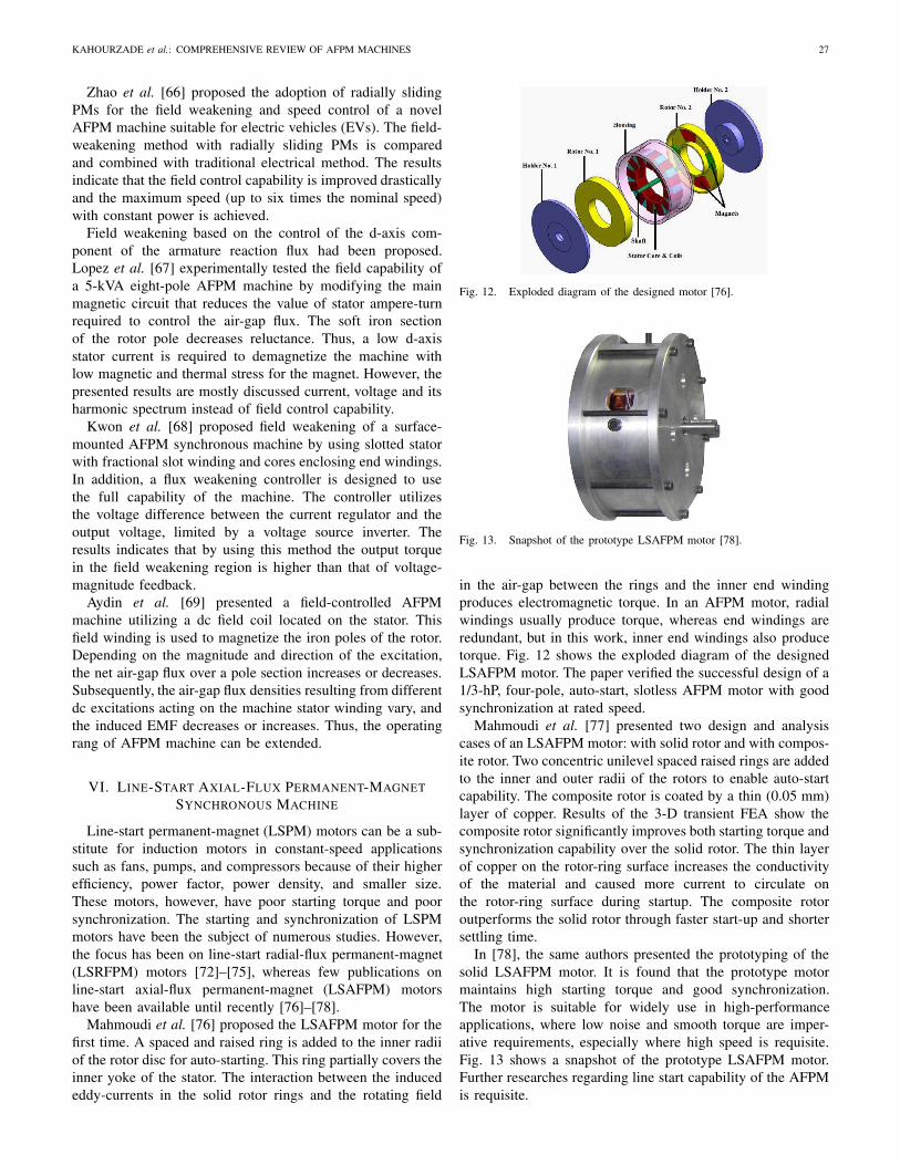
Mahmoudi et al. [76] proposed the LSAFPM motor for thefirst time. A spaced and raised ring is added to the inner radiiof the rotor disc for auto-starting. This ring partially covers theinner yoke of the stator. The interaction between the inducededdy-currents in the solid rotor rings and the rotating field
Fig. 12. Exploded diagram of the designed motor [76].
Fig. 13. Snapshot of the prototype LSAFPM motor [78].
in the air-gap between the rings and the inner end windingproduces electromagnetic torque. In an AFPM motor, radialwindings usually produce torque, whereas end windings areredundant, but in this work, inner end windings also producetorque. Fig. 12 shows the exploded diagram of the designedLSAFPM motor. The paper verified the successful design of a1/3-hP, four-pole, auto-start, slotless AFPM motor with goodsynchronization at rated speed.
Mahmoudi et al. [77] presented two design and analysiscases of an LSAFPM motor: with solid rotor and with compos-ite rotor. Two concentric unilevel spaced raised rings are addedto the inner and outer radii of the rotors to enable auto-startcapability. The composite rotor is coated by a thin (0.05 mm)layer of copper. Results of the 3-D transient FEA show thecomposite rotor significantly improves both starting torque andsynchronization capability over the solid rotor. The thin layerof copper on the rotor-ring surface increases the conductivityof the material and caused more current to circulate onthe rotor-ring surface during startup. The composite rotoroutperforms the solid rotor through faster start-up and shortersettling time.
In [78], the same authors presented the prototyping of thesolid LSAFPM motor. It is found that the prototype motormaintains high starting torque and good synchronization.The motor is suitable for widely use in high-performanceapplications, where low noise and smooth torque are imper-ative requirements, especially where high speed is requisite.Fig. 13 shows a snapshot of the prototype LSAFPM motor.Further researches regarding line start capability of the AFPMis requisite.
28 CANADIAN JOURNAL OF ELECTRICAL AND COMPUTER ENGINEERING, VOL. 37, NO. 1, WINTER 2014
Fig. 14. Basic components of the designed axial-flux motor.
VII. MATERIALS
The demand for electrical machines with low weight,reduced loss, and increased power density has resulted incomprehensive studies on the application of new materials inthe structure of AFPM machines. Application of amorphousmagnetic materials (AMM), soft magnetic composites (SMC),grain oriented steel, charged polymers, superconductors,redundant material, and plastic in construction of AFPMmachines have been reviewed in recent articles [79]–[86].
Eastham et al. [79] developed an AFPM machine utilizingfour plastic discs as the rotor disc, two internal discs to supportPMs, and two external discs to support PMs, in addition to oneiron ring for flux path closure. The stator consists of threelarger diameter discs containing coils. Fig. 14 shows the half-section scheme and the design construction. The compositematerials in the construction are nonconductive. Thus, the lossin the two iron rings is attributed only to small space harmonicfluxes and hence, the efficiency of the machine is improved.
Holmes et al. [80] constructed a DSSR AFPM micropowergenerator from a polymer rotor with embedded PMs sand-wiched between two silicon stators with electroplated planarcoils. The effect of design elements such as the number oflayers of stator coils, air-gap length, and application of softmagnetic pole pieces on the stators have been investigated.It was concluded that higher output powers could be achievedby reducing the rotor-stator gap, enhancing the coil fill-factorincreasing the number of poles, or increasing the number ofcoil layers on each stator.
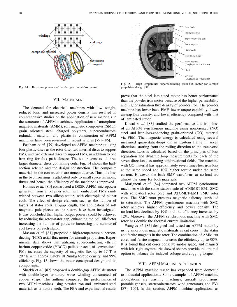
Masson et al. [81] proposed a high-temperature supercon-ducting (HTC) axial-flux motor for aircraft propulsion. Exper-imental data shows that utilizing superconducting yttriumbarium copper oxide (YBCO) pellets instead of conventionalPMs increases the capacity of magnetic flux up to 17 T at29 °K with approximately 18 Nm/kg torque density, and 99%efficiency. Fig. 15 shows the motor conceptual design and itscomponents.
Sharkh et al. [82] proposed a double-gap AFPM dc motorwith double-layer armature wave winding constructed ofcopper strips. The authors compared the performance oftwo AFPM machines using powder iron and laminated steelmaterials as armature teeth. The FEA and experimental results
Fig. 15. High temperature superconducting axial-flux motor for aircraftpropulsion design [81].
prove that the steel laminated motor has better performancethan the powder iron motor because of the higher permeabilityand higher saturation flux density of powder iron. The powdermachine has lower back EMF, lower torque capability, lowerair-gap flux density, and lower efficiency compared with thatof laminated stator.
Kowal et al. [83] studied the performance and iron lossof an AFPM synchronous machine using nonoriented (NO)steel and iron-loss-enhancing grain-oriented (GO) materialvia FEM. The magnetic energy is calculated using severalmeasured quasi-static-loops on an Epstein frame in sevendirections starting from the rolling direction to the transversedirection. Loss is calculated based on the principles of lossseparation and dynamic loop measurements for each of theseven directions, assuming unidirectional fields. The machinewith GO material has approximately seven times less iron lossat the same speed and 10% higher torque under the samecurrent. However, the back-EMF waveforms at no-load arealmost the same for both materials.
Marignetti et al. [84] compared two AFPM synchronousmachines with the same stator made of ATOMET-EM1 SMCwith solid-steel rotor core and ATOMET-EM1 SMC rotorcore. The SMC rotor presents magnetic saliency attributedto saturation. The AFPM synchronous machine with SMCrotor achieves higher efficiency and power density. Theno-load loss declines by 19%, and the efficiency increases by12%. Moreover, the AFPM synchronous machine with SMCrotor has double the thermal current limitation.
Wang et al. [85] designed and tested an AFPM motor byusing amorphous magnetic materials as cut cores in the statorand ferrite magnets in the rotor. The combination of AMM cutcores and ferrite magnets increases the efficiency up to 90%.It is found that cut cores conserve motor space, and magnetswith left–right asymmetric skewed shapes provide the optimaloption to balance the induced voltage and cogging torque.
VIII. AFPM MACHINE APPLICATION
The AFPM machine usage has expanded from domesticto industrial applications. Some examples of AFPM machineapplications are washing machines, aircraft propulsions,portable gensets, starter/alternators, wind generators, and EVs[87]–[105]. In this section, AFPM machine applications as

KAHOURZADE et al.: COMPREHENSIVE REVIEW OF AFPM MACHINES 29
wind generators and EVs presented in the recent articles arereviewed because of the popularity of AFPM machines forthese applications.
The AFPM synchronous generator is considered to bea suitable energy converter for direct-coupled wind turbineapplications [87], [88]. Coreless AFPM generators are pro-posed for various power generation applications, particularlyin direct-drives over a wide operational speed range. Lowcogging torque and high efficiency caused by the eliminationof stator teeth and back-iron yoke are the advantages of acoreless design [89].
Brisset et al. [90] determined the best configuration of5-MW nine-phase concentrated-winding direct-drive windgenerator. Analytical sizing model and multiobjective opti-mization are applied to minimize the total active mass andto maximize the power factor considering the technologicalconstraints and temperatures. Pareto front method is usedto select the best configuration and design parameter valuesamong six different configurations.
Lee et al. [91] proposed the design optimization of anAFPM generator for battery charging applications. The designobjects include size, weight, and efficiency. Size optimizationis achieved by applying an SMC core instead of a silicon steelcore. Although some differences exist between the simulationand experimental results because of the air-gap prototypingerror, the authors claim that the proposed generator is capableof charging a 50-Wh battery within the speed boundary whichis based on the design specifications.
The concept of applying AFPM motors in EVs was firstproposed in the 1990s. Over the past 20 years, several studieshave been conducted on the design of AFPM machines tooptimize the performance of EVs. Oh et al. [92] simulateand test the capability of an AFPM motor for hybrid EVs byusing a vehicle simulator. The efficiency map of the motor isdeveloped for various operating conditions. The performanceof the motor for various drive cycles and optimal air-gap valuesis determined based on the hardware in loop concept. Themotor speed follows the speed commands under variable gapconditions. The advantages of the design include extendedoperating speed range and high efficiency.
Rahman et al. [93] presented a direct-drive SSDR AFPMmotor for fuel cell EV and HEV propulsion application.Adding magnetic wedges in the stator slots increases the powerrange by more than two times. This process also decreasescore loss and increases efficiency. Power loss is minimizedby the application of high thermal conductivity epoxy joiningmachine stator and liquid-cooled aluminum casing. The massof the machine, as well as cogging torque and torque ripple,is minimized.
Yang et al. [94] proposed the optimal design and controlof an SSDR AFPM motor mounted inside the wheel withoutmechanical transmission and differential gears for electricpassenger cars. The FEA results indicate that the design hasthe capability to drive a 600-kg passenger car with accelerationfrom 0 to 40 km/h in 5 s on a 15° incline. Critical designparameters including maximum torque, efficiency, rated speed,minimum weight, materials, and power source are determinedusing sensitivity analyses.
Nguyen et al. [95] proposed an AFPM machine designedfor a flywheel energy storage system with the objective ofachieving high efficiency, zero fundamental frequency rotorloss, low cogging torque, and improved back-EMF waveforms.The design includes two sets of three-phase stator windingsand requires only one power converter to supply power forthe control of both axial force and electromagnetic torque.The optimal PM skew angle to achieve the minimum coggingtorque, considering minimum effect on the static axial force,is presented.
In addition to the mentioned applications, AFPM machinesare becoming popular in other industries such as, ship propul-sion [96], direct drive elevator [97], hard disc [98], microp-ower generator [99], induction heating genes [100], slimvortex pump [101], flywheel energy storage system [102],automobile alternator [103], [104], and microenergy storagesystem [105].
IX. COMPARISON
Performance comparison among AFPM machines, RFPMmachines, and transverse flux PM (TFPM) machines havebeen studied extensively [106]–[110]. This section reviewsthe publication conducted on the performance comparison ofdifferent PM machines.
In [106], authors compared the performance of AFPMmachine with the RFPM machine considering following cri-teria: required copper, steel, and magnet weights, copper andiron loss, moment of inertia, torque per unit moment of inertia,power per unit active weight, and power per unit active vol-ume. The presented results are based on the performance of theRFPM machine and four AFPM configurations including theslotted and slotless SSSR AFPM and the slotted and slotlessDSSR AFPM topologies. For five various output power levels,it is concluded that AFPM machines are more promising interms of volume, power density, required iron, active weight,torque, and rotor moment of inertia. The required PM materialfor the slotless AFPM machines is more than the RFPMmachine. However, the slotted AFPM machines requires less.The copper loss in the slotless DSSR AFPM machines ishigher than that of the slotted RFPM field machine.
Cavagnino et al. [107] compared the DSSR AFPM motorperformance with RFPM machine in terms of provided elec-tromagnetic torque and torque density, when the overall motorvolume, losses per surface, and the air-gap flux density are keptconstant. The pole numbers influence and the end-windingsencumbrances are also take into account. The proposed pro-cedure is based on simple thermal considerations. The resultsindicate that AFPM configuration has better performance interms of electromagnetic torque and torque density if thenumber of poles is high (more than 10) and the axial lengthis short.
Chen et al. [108] performed the comparison among theRFPM, multistage AFPM, and three-phase TFPM machinesunder small current density, small electrical loading, hightemperature, constant speed, and without an external coolingsystem condition. It was concluded that owing to the limitedouter diameter, the multistage AFPM topology is not suitable

30 CANADIAN JOURNAL OF ELECTRICAL AND COMPUTER ENGINEERING, VOL. 37, NO. 1, WINTER 2014
Fig. 16. Heat dissipation comparison of 200 HP, six-pole 1200 r/min radialand axial-flux surface-mounted permanent magnet machines [110].
as it has low torque density and low efficiency; the TFPMtopology has high torque density but a low power factor;the RFPM machine has a simple construction, a high torquedensity and the best power factor; therefore, it is declared themost suitable within these design constraints.
Pippuri et al. [109] compared the torque density RFPM,AFPM, and TFPM machines of a 10-kW 200-r/min examplemachine. The achieved results of the Pareto optimal frontsmethod shows that the best RFPM motor designs in termsof efficiency and compactness have a pole pair number from8 to 10. The AFPM topology was found to perform the bestwith pole pair numbers 10–12. The lowest pole pair numberswere found to be the least feasible when a compact yet energyefficient solution is sought after.
In Qu et al. [110] compared the performance of 200 HP,six-pole 1200-r/min RFPM and Double-sided AFPM machinesconsidering different PM configurations using sizing equa-tions. The results indicate that SSDR machines have higherpower density and efficiency while SSDR-NS machine has thehighest power/torque density ratio and efficiency. The DSSR-type machines are better than the others in terms of weightand utilization where DSSR-SS configuration has the lowestweight and highest utilization factor. The heat dissipationcomparison results presented in Fig. 16 indicates DSSR-NS and RFPM-SS configurations have the best and worstdissipation capability, respectively.
X. CONCLUSION
A comprehensive review on the recent advances onAFPM machines has been presented in this paper. TheAFPM machine topologies, design, performance analysis, fieldcontrol, material selection, application, and performance incomparison with other PM machines have been considered.The design and analysis of the line-start AFPM motors havebeen discussed. The performance analyses including elec-tromagnetic, cogging torque, thermal, and mechanical andmanufacturing analysis have been reviewed. The applicationof AFPM generators in wind energy systems and AFPMmotors in electric vehicles are totemic of this technologyfor contribution in energy saving and combating environmentpollution. This paper presented the works of various eminent
authors in the related publications with the aim of providinga useful guideline for researches and practicing engineers onthe latest development of AFPM machines.
REFERENCES
[1] Y. J. Cao, Y. K. Huang, and J. Long, “Research on axial magnetic forceand rotor mechanical stress of an air-cored axial-flux permanent magnetmachine based on 3D FEM,” Appl. Mech. Mater., vol. 105, pp. 160–163,Sep. 2012.
[2] A. Mahmoudi, S. Kahourzade, N. A. Rahim, W. P. Hew, andM. N. Uddin, “Design and prototyping of an optimised axial-fluxpermanent-magnet synchronous machine,” IET Electr. Power Appl.,vol. 7, no. 5, pp. 338–349, 2013.
[3] T. Cook, “Improvement in electro-magnetic machines,” U.S. Patent1 735, Aug. 25, 1840.
[4] J. F. Gieras, R.-J. Wang, and M. J. Kamper, Axial Flux PermanentMagnet Brushless Machines. New York, NY, USA: Springer-Verlag,2008.
[5] S. M. Mirimani, A. Vahedi, and F. Marignetti, “Effect of inclinedstatic eccentricity fault in single stator-single rotor axial flux permanentmagnet machines,” IEEE Trans. Magn., vol. 48, no. 1, pp. 143–149,Jan. 2012.
[6] H. Hakala, “Integration of motor and hoisting machine changesthe elevator business,” in Proc. Int. Conf. Electr. Mach., 2000,pp. 1242–1245.
[7] C. Chan, “Axial-field electrical machines-design and applications,” IEEETrans. Energy Convers., vol. 2, no. 2, pp. 294–300, Jun. 1987.
[8] C. T. Liu, T. S. Chiang, J. F. D. Zamora, and S. C. Lin, “Field-oriented control evaluations of a single-sided permanent magnet axial-flux motor for an electric vehicle,” IEEE Trans. Magn., vol. 39, no. 5,pp. 3280–3282, Sep. 2003.
[9] A. Parviainen, M. Niemela, and J. Pyrhonen, “Modeling of axial fluxpermanent-magnet machines,” IEEE Trans. Ind. Appl., vol. 40, no. 5,pp. 1333–1340, Oct. 2004.
[10] M. Aydin, H. Surong, and T. A. Lipo, “Torque quality and com-parison of internal and external rotor axial flux surface-magnet discmachines,” IEEE Trans. Ind. Electron., vol. 53, no. 3, pp. 822–830,Jun. 2006.
[11] M. Aydin, S. Huang, and T. A. Lipo, “Axial flux permanent mag-net disc machines: A review,” in Proc. Int. SPEEDAM, Jun. 2004,pp. 61–71.
[12] A. Cavagnino, M. Lazzari, F. Profumo, and A. Tenconi, “Axial fluxinterior PM synchronous motor: Parameters identification and steady-state performance measurements,” IEEE Trans. Ind. Appl., vol. 36, no. 6,pp. 1581–1588, Dec. 2000.
[13] F. Caricchi, F. Crescimbini, O. Honorati, G. L. Bianco, and E. Santini,“Performance of coreless-winding axial-flux permanent-magnet genera-tor with power output at 400 Hz, 3000 r/min,” IEEE Trans. Ind. Appl.,vol. 34, no. 6, pp. 1263–1269, Dec. 1998.
[14] F. Profumo, Z. Zheng, and A. Tenconi, “Axial flux machines drives:A new viable solution for electric cars,” IEEE Trans. Ind. Electron.,vol. 44, no. 1, pp. 39–45, Feb. 1997.
[15] S. Huang, M. Aydin, and T. A. Lipo, “TORUS concept machines:Pre-prototyping design assessment for two major topologies,” in Proc.IEEE Ind. Appl. Conf. Rec. 36th IAS Annu. Meeting, Oct. 2001,pp. 1619–1625.
[16] F. Caricchi, F. G. Capponi, F. Crescimbini, and L. Solero, “Experimentalstudy on reducing cogging torque and no-load power loss in axial-fluxpermanent-magnet machines with slotted winding,” IEEE Trans. Ind.Appl., vol. 40, no. 4, pp. 1066–1075, Aug. 2004.
[17] F. Locment, E. Semail, and F. Piriou, “Design and study of a multiphaseaxial-flux machine,” IEEE Trans. Magn., vol. 42, no. 4, pp. 1427–1430,Apr. 2006.
[18] M. J. Kamper, W. R. Jie, and F. G. Rossouw, “Analysis and performanceof axial flux permanent-magnet machine with air-cored nonoverlappingconcentrated stator windings,” IEEE Trans. Ind. Appl., vol. 44, no. 5,pp. 1495–1504, Oct. 2008.
[19] N. Lombard and M. Kamper, “Analysis and performance of an ironlessstator axial flux PM machine,” IEEE Trans. Energy Convers., vol. 14,no. 4, pp. 1051–1056, Dec. 1999.
[20] F. Caricchi, F. Crescimbini, F. Mezzetti, and E. Santini, “Multistageaxial-flux PM machine for wheel direct drive,” IEEE Trans. Ind. Appl.,vol. 32, no. 4, pp. 882–888, Aug. 1996.

KAHOURZADE et al.: COMPREHENSIVE REVIEW OF AFPM MACHINES 31
[21] F. Caricchi, F. Crescimbini, and E. Santini, “Basic principle and designcriteria of axial-flux PM machines having counterrotating rotors,” IEEETrans. Ind. Appl., vol. 31, no. 5, pp. 1062–1068, Oct. 1995.
[22] A. Chen, R. Nilssen, and A. Nysveen, “Performance comparisons amongradial-flux, multistage axial-flux, and three-phase transverse-flux PMmachines for downhole applications,” IEEE Trans. Ind. Appl., vol. 46,no. 2, pp. 779–789, Apr. 2010.
[23] O. Kalender, Y. Ege, and S. Nazlibilek, “Design and determinationof stator geometry for axial flux permanent magnet free rod rotorsynchronous motor,” Measurement, vol. 44, no. 9, pp. 1753–1760, 2011.
[24] S. Huang, J. L. F. Leonardi, and T. A. Lipo, “A comparison ofpower density for axial flux machines based on general purpose sizingequations,” IEEE Trans. Energy Convers., vol. 14, no. 2, pp. 185–192,Jun. 1999.
[25] M. Aydin, S. Hum, and T. A. Lipo, “Design and 3D electromagneticfield analysis of non-slotted and slotted TORUS type axial flux surfacemounted permanent magnet disc machines,” in Proc. IEEE IEMDC, Jun.2001, pp. 645–651.
[26] T. Chan and L. Lai, “An axial-flux permanent-magnet synchronousgenerator for a direct-coupled wind-turbine system,” IEEE Trans. EnergyConvers., vol. 22, no. 1, pp. 86–94, Mar. 2007.
[27] Y. P. Yang, Y. P. Luh, C. H. Cheung, J. P. Wang, and S. W. Wu,“Design and control of axial-flux brushless DC wheel motors for electricvehicles-part I: Multi objective optimal design and analysis,” IEEETrans. Magn., vol. 40, no. 4, pp. 1873–1882, Jul. 2004.
[28] C. C. Hwang, P. L. Li, F. C. Chuang, C. T. Liu, and K. H. Huang,“Optimization for reduction of torque ripple in an axial flux permanentmagnet machine,” IEEE Trans. Magn., vol. 45, no. 3, pp. 1760–1763,Mar. 2009.
[29] S. Rao, Optimization Theory and Applications. Hoboken, NJ, USA:Wiley, 1984.
[30] N. Rostami, M. R. Feyzi, J. Pyrhönen, A. Parviainen, andV. Behjat, “Genetic algorithm approach for improved design of a variablespeed axial-flux permanent-magnet synchronous generator,” IEEE Trans.Magn., vol. 48, no. 12, pp. 4860–4865, Dec. 2012.
[31] A. Mahmoudi, S. Kahourzade, N. A. Rahim, and W. P. Hew, “Design,analysis, and prototyping of an axial-flux permanent-magnet motor basedon genetic algorithm and finite element analysis,” IEEE Trans. Magn.,vol. 49, no. 4, pp. 1479–1492, Apr. 2013.
[32] S. Kahourzade, A. Gandomkar, A. Mahmoudi, N. A. Rahim, W. P. Hew,and M. N. Uddin, “Design optimization and analysis of AFPM synchro-nous machine incorporating power density, thermal analysis, and back-EMF THD,” Progr. Electromag. Res., vol. 136, pp. 327–367, Jan. 2013.
[33] S. Y. Sung, J. H. Jeong, Y. S. Park, J. Y. Choi, and S. M. Jang, “Improvedanalytical modeling of axial flux machine with a double-sided permanentmagnet rotor and slotless stator based on an analytical method,” IEEETrans. Magn., vol. 48, no. 11, pp. 2945–2948, Nov. 2012.
[34] S. H. Lee et al., “Characteristic analysis of the slotless axial-flux typebrushless DC motors using image method,” IEEE Trans. Magn., vol. 42,no. 4, pp. 1327–1330, Apr. 2006.
[35] T. F. Chan, L. L. Lai, and S. Xie, “Field computation for an axialflux permanent-magnet synchronous generator,” IEEE Trans. EnergyConvers., vol. 24, no. 1, pp. 1–11, Mar. 2009.
[36] Y. Huang, B. Ge, J. Dong, H. Lin, J. Zhu, and Y. Gu, “3-D analyticalmodeling of no-load magnetic field of ironless axial flux permanentmagnet machine,” IEEE Trans. Magn., vol. 48, no. 11, pp. 2929–2932,Nov. 2012.
[37] O. de la Barrière, S. Hlioui, H. B. Ahmed, M. Gabsi, and M. LoBue,“3-D formal resolution of Maxwell equations for the computation of theno-load flux in an axial flux permanent-magnet synchronous machine,”IEEE Trans. Magn., vol. 48, no. 1, pp. 128–136, Jan. 2012.
[38] Z. Zhu and D. Howe, “Influence of design parameters on cogging torquein permanent magnet machines,” IEEE Trans. Energy Convers., vol. 15,no. 4, pp. 407–412, Dec. 2000.
[39] G. Barakat, T. E. Meslouhi, and B. Dakyo, “Analysis of the coggingtorque behavior of a two-phase axial flux permanent magnet synchro-nous machine,” IEEE Trans. Magn., vol. 37, no. 4, pp. 2803–2805,Jul. 2001.
[40] H. Tiegna, A. Bellara, Y. Amara, and G. Barakat, “Analytical modelingof the open-circuit magnetic field in axial flux permanent-magnetmachines with semi-closed slots,” IEEE Trans. Magn., vol. 48, no. 3,pp. 1212–1226, Mar. 2012.
[41] M. Aydin, Q. Ronghai, and T. A. Lipo, “Cogging torque minimizationtechnique for multiple-rotor, axial-flux, surface-mounted-PM motors:Alternating magnet pole-arcs in facing rotors,” in Proc. 38th IAS Annu.Meeting Conf. Rec. Ind. Appl. Conf., Oct. 2003, pp. 555–561.
[42] A. B. Letelier, D. A. Gonzalez, J. A. Tapia, R. Wallace, andM. A. Valenzuela, “Cogging torque reduction in an axial flux PMmachine via stator slot displacement and skewing,” IEEE Trans. Ind.Appl., vol. 43, no. 3, pp. 685–693, Jun. 2007.
[43] D. A. Gonzalez, J. A. Tapia, and A. L. Bettancourt, “Design considera-tion to reduce cogging torque in axial flux permanent-magnet machines,”IEEE Trans. Magn., vol. 43, no. 8, pp. 3435–3440, Aug. 2007.
[44] T. Brown, G. Heins, S. Hobbs, M. Thiele, and J. Davey, “Cogging torqueprediction for mass-produced axial flux PMSM stators,” in Proc. IEEEIEMDC, May 2011, pp. 206–211.
[45] D. K. Woo, J. H. Choi, M. Ali, and J. H. Kyo, “A novel multimodaloptimization algorithm applied to electromagnetic optimization,” IEEETrans. Magn., vol. 47, no. 6, pp. 1667–1673, Jun. 2011.
[46] G. De Donato, F. G. Capponi, G. A. Rivellini, and F. Caricchi, “Integral-slot versus fractional-slot concentrated-winding axial-flux permanent-magnet machines: Comparative design, FEA, and experimental tests,”IEEE Trans. Ind. Appl., vol. 48, no. 5, pp. 1487–1495, Oct. 2012.
[47] A. Boglietti, A. Cavagnino, D. Staton, M. Shanel, M. Mueller, andC. Mejuto, “Evolution and modern approaches for thermal analysisof electrical machines,” IEEE Trans. Ind. Electron., vol. 56, no. 3,pp. 871–882, Mar. 2009.
[48] D. A. Howey, P. R. N. Childs, and A. S. Holmes, “Air-gap convection inrotating electrical machines,” IEEE Trans. Ind. Electron., vol. 59, no. 3,pp. 1367–1375, Mar. 2012.
[49] H. Sugimoto et al., “Development of an axial flux type PM synchronousmotor with the liquid nitrogen cooled HTS armature windings,” IEEETrans. Appl. Supercond., vol. 17, no. 2, pp. 1637–1640, Jun. 2007.
[50] C. H. Lim, G. Airoldi, R. G. Dominy, and K. Mahkamov, “Experimentalvalidation of CFD modelling for heat transfer coefficient predictions inaxial flux permanent magnet generators,” Int. J. Thermal Sci., vol. 50,no. 12, pp. 2451–2463, 2011.
[51] F. Marignetti, V. D. Colli, and Y. Coia, “Design of axial flux PMsynchronous machines through 3-D coupled electromagnetic thermaland fluid-dynamical finite-element analysis,” IEEE Trans. Ind. Electron.,vol. 55, no. 10, pp. 3591–3601, Oct. 2008.
[52] D. A. Howey, A. S. Holmes, and K. R. Pullen, “Measurement and CFDprediction of heat transfer in air-cooled disc-type electrical machines,”IEEE Trans. Ind. Appl., vol. 47, no. 4, pp. 1716–1723, Aug. 2011.
[53] C. H. Lim et al., “2-D lumped-parameter thermal modelling of axialflux permanent magnet generators,” in Proc. 18th ICEM, 2008, pp. 1–6.
[54] N. Rostami, M. Feyzi, J. Pyrhonen, A. Parviainen, and M. Niemela,“Lumped-parameter thermal model for axial flux permanent mag-net machines,” IEEE Trans. Magn., vol. 49, no. 3, pp. 1178–1184,Mar. 2013.
[55] G. Airoldi et al., “Computations on heat transfer in axial flux permanentmagnet machines,” in Proc. 18th ICEM, 2008, pp. 1–6.
[56] Y. Chong, D. A. Magahy, J. Chick, M. A. Mueller, D. A. Staton, andA. S. McDonald, “Numerical modelling of an axial flux permanentmagnet machine for convection heat transfer,” in Proc. IET Conf. RPG,Sep. 2011, pp. 1–6.
[57] C. T. Liu, T. S. Chiang, J. F. D. Zamora, and S. C. Lin, “Optimaloperational strategy design of a single-sided permanent magnet axial-flux motor for electrical vehicle application,” in Proc. Ind. Appl. Conf.38th Rec. IAS Annu. Meeting., vol. 3. Oct. 2003, pp. 1677–1683.
[58] H. Vansompel, P. Sergeant, and L. Dupre, “Optimized design consideringthe mass influence of an axial flux permanent-magnet synchronousgenerator with concentrated pole windings,” IEEE Trans. Magn., vol. 46,no. 12, pp. 4101–4107, Dec. 2010.
[59] W. Fei, P. C. K. Luk, and T. S. E. Hasan, “Rotor integrity design fora high-speed modular air-cored axial-flux permanent-magnet generator,”IEEE Trans. Ind. Electron., vol. 58, no. 9, pp. 3848–3858, Sep. 2011.
[60] A. Di Gerlando, G. Foglia, M. F. Iacchetti, and R. Perini, “Axial fluxPM machines with concentrated armature windings: Design analysis andtest validation of wind energy generators,” IEEE Trans. Ind. Electron.,vol. 58, no. 9, pp. 3795–3805, Sep. 2011.
[61] S. H. Lee, D. J. Kim, J. P. Hong, and J. H. Park, “Characteristiccomparison between the spiral and the lamination stator in axial fieldslotless machines,” IEEE Trans. Magn., vol. 45, no. 10, pp. 4547–4549,Oct. 2009.
[62] G. De Donato, F. G. Capponi, and F. Caricchi, “On the use of magneticwedges in axial flux permanent magnet machines,” IEEE Trans. Ind.Electron., vol. 60, no. 11, pp. 4831–4840, Nov. 2013.
[63] G. De Donato, F. G. Capponi, and F. Caricchi, “No-load perfor-mance of axial flux permanent magnet machines mounting magneticwedges,” IEEE Trans. Ind. Electron., vol. 59, no. 10, pp. 3768–3779,Oct. 2012.

32 CANADIAN JOURNAL OF ELECTRICAL AND COMPUTER ENGINEERING, VOL. 37, NO. 1, WINTER 2014
[64] L. Del Ferraro, F. Caricchi, and F. G. Capponi, “Analysis and comparisonof a speed-dependant and a torque-dependant mechanical device for wideconstant power speed range in AFPM starter/alternators,” IEEE Trans.Power Electron., vol. 21, no. 3, pp. 720–729, May 2006.
[65] F. Giulii Capponi, R. Terrigi, F. Caricchi, and L. Del Ferraro, “Activeoutput voltage regulation for an ironless axial-flux PM automotivealternator with electromechanical flux weakening,” IEEE Trans. Ind.Appl., vol. 45, no. 5, pp. 1785–1793, Sep./Oct. 2009.
[66] J. Zhao et al., “Field weakening capability investigation of an axial fluxpermanent-magnet synchronous machine with radially sliding permanentmagnets used for electric vehicles,” J. Appl. Phys., vol. 111, no. 7,pp. 07A719-1–07A719-3, 2012.
[67] D. A. González-Lopez, J. A. Tapia, R. Wallace, and A. Valenzuela,“Design and test of an axial flux permanent-magnet machine with fieldcontrol capability,” IEEE Trans. Magn., vol. 44, no. 9, pp. 2168–2173,Sep. 2008.
[68] T. S. Kwon, S. K. Sul, L. Alberti, and N. Bianchi, “Design and controlof an axial-flux machine for a wide flux-weakening operation region,”IEEE Trans. Ind. Appl., vol. 45, no. 4, pp. 1258–1266, Aug. 2009.
[69] M. Aydin, S. Huang, and T. Lipo, “Design, analysis, and control of ahybrid field-controlled axial-flux permanent-magnet motor,” IEEE Trans.Ind. Electron., vol. 57, no. 1, pp. 78–87, Jan. 2010.
[70] L. Ping-Yi and L. Yen-Shin, “Voltage control technique for the extensionof DC-link voltage utilization of finite-speed SPMSM drives,” IEEETrans. Ind. Electron., vol. 59, no. 9, pp. 3392–3402, Sep. 2012.
[71] I. Boldea, M. C. Paicu, and G. D. Andreescu, “Active flux conceptfor motion-sensorless unified AC drives,” IEEE Trans. Power Electron.,vol. 23, no. 5, pp. 2612–2618, Sep. 2008.
[72] A. H. Isfahani and S. Vaez-Zadeh, “Effects of magnetizing inductance onstart-up and synchronization of line-start permanent-magnet synchronousmotors,” IEEE Trans. Magn., vol. 47, no. 4, pp. 823–829, Apr. 2011.
[73] M. A. Rahman et al., “Advances on single phase line-start high efficiencyinterior permanent magnet motors,” IEEE Trans. Ind. Electron., vol. 59,no. 3, pp. 1333–1345, Mar. 2012.
[74] B. H. Lee, J. P. Hong, and J. H. Lee, “Optimum design criteria formaximum torque and efficiency of a line-start permanent-magnet motorusing response surface methodology and finite element method,” IEEETrans. Magn., vol. 48, no. 2, pp. 863–866, Feb. 2012.
[75] P. Guglielmi, B. Boazzo, E. Armando, G. Pellegrino, and A. Vagati,“Permanent magnet minimization in PM assisted synchronous reluctancemotor for wide speed range,” IEEE Trans. Ind. Appl., vol. 49, no. 1,pp. 31–41, Feb. 2013.
[76] A. Mahmoudi, S. Kahourzade, N. A. Rahim, W. P. Hew, andN. F. Ershad, “Slot-less torus solid-rotor-ringed line-start axial-flux permanent-magnet motor,” Progr. Electromagn. Res., vol. 131,pp. 331–355, Nov. 2012.
[77] A. Mahmoudi, S. Kahourzade, N. A. Rahim, and W. P. Hew,“Improvement to performance of solid-rotor-ringed line-start axial-flux permanent-magnet motor,” Progr. Electromagn. Res., vol. 124,pp. 383–404, Apr. 2012.
[78] A. Mahmoudi, S. Kahourzade, N. A. Rahim, W. P. Hew, and M. Uddin,“Design, analysis, and prototyping of a novel-structured solid-rotor-ringed line-start axial-flux permanent-magnet motor,” IEEE Trans. Ind.Electron., vol. 61, no. 4, pp. 1722–1734, Apr. 2014.
[79] J. F. Eastham, F. Profumo, A. Tenconi, R. H. Cottingham, P. Coles, andG. Gianolio, “Novel axial flux machine for aircraft drive: Design andmodeling,” IEEE Trans. Magn., vol. 38, no. 5, pp. 3003–3005, Sep. 2002.
[80] A. S. Holmes, H. Hong, and K. R. Pullen, “Axial-flux permanentmagnet machines for micropower generation,” J. Microelectromech.Syst., vol. 14, no. 1, pp. 54–62, Feb. 2005.
[81] P. J. Masson, M. Breschi, P. Tixador, and C. A. Luongo, “Design of HTSaxial flux motor for aircraft propulsion,” IEEE Trans. Appl. Supercond.,vol. 17, no. 2, pp. 1533–1536, Jun. 2007.
[82] S. M. A. Sharkh and M. T. N. Mohammad, “Axial field permanentmagnet DC motor with powder iron armature,” IEEE Trans. EnergyConvers., vol. 22, no. 3, pp. 608–613, Sep. 2007.
[83] D. Kowal, P. Sergeant, L. Dupre, and A. V. Bossche, “Comparisonof nonoriented and grain-oriented material in an axial flux permanent-magnet machine,” IEEE Trans. Magn., vol. 46, no. 2, pp. 279–285,Feb. 2010.
[84] F. Marignetti, V. D. Colli, and S. Carbone, “Comparison of axial fluxPM synchronous machines with different rotor back cores,” IEEE Trans.Magn., vol. 46, no. 2, pp. 598–601, Feb. 2010.
[85] Z. Wang et al., “Development of an axial gap motor with amorphousmetal cores,” IEEE Trans. Ind. Appl., vol. 47, no. 3, pp. 1293–1299,Jun. 2011.
[86] H. Jagau, M. A. Khan, and P. S. Barendse, “Design of a sustainablewind generator system using redundant materials,” in Proc. IEEE ECCE,Sep. 2011, pp. 1628–1635.
[87] T. F. Chan, W. Wang, and L. L. Lai, “Magnetic field in a transverse-and axial-flux permanent magnet synchronous generator from 3-DFEA,” IEEE Trans. Magn., vol. 48, no. 2, pp. 1055–1058,Feb. 2012.
[88] L. Hao, M. Lin, X. Zhao, X. Fu, Z. Q. Zhu, and P. Jin, “Staticcharacteristics analysis and experimental study of a novel axial field flux-switching permanent magnet generator,” IEEE Trans. Magn., vol. 48,no. 11, pp. 4212–4215, Nov. 2012.
[89] W. Wang, K. W. E. Cheng, K. Ding, and L. C. Meng, “A novelapproach to the analysis of the axial-flux permanent-magnet generatorwith coreless stator supplying a rectifier load,” IEEE Trans. Magn.,vol. 47, no. 10, pp. 2391–2394, Oct. 2011.
[90] S. Brisset, D. Vizireanu, and P. Brochet, “Design and optimization ofa nine-phase axial-flux PM synchronous generator with concentratedwinding for direct-drive wind turbine,” IEEE Trans. Ind. Appl., vol. 44,no. 3, pp. 707–715, Jun. 2008.
[91] J. Y. Lee, D. H. Koo, S. R. Moon, and C. K. Han, “Design ofan axial flux permanent magnet generator for a portable hand crankgenerating system,” IEEE Trans. Magn., vol. 48, no. 11, pp. 2977–2980,Nov. 2012.
[92] S. C. Oh and A. Emadi, “Test and simulation of axial flux-motorcharacteristics for hybrid electric vehicles,” IEEE Trans. Veh. Technol.,vol. 53, no. 3, pp. 912–919, May 2004.
[93] K. Rahman, N. Patel, T. Ward, J. Nagashima, F. Caricchi, andF. Crescimbini, “Application of direct-drive wheel motor for fuel cellelectric and hybrid electric vehicle propulsion system,” IEEE Trans. Ind.Appl., vol. 42, no. 5, pp. 1185–1192, Oct. 2006.
[94] Y. P. Yang and D. S. Chuang, “Optimal design and control of a wheelmotor for electric passenger cars,” IEEE Trans. Magn., vol. 43, no. 1,pp. 51–61, Jan. 2007.
[95] T. D. Nguyen, K. J. Tseng, S. Zhang, and H. T. Nguyen, “A novel axialflux permanent-magnet machine for flywheel energy storage system:Design and analysis,” IEEE Trans. Ind. Electron., vol. 58, no. 9,pp. 3784–3794, Sep. 2011.
[96] F. Caricchi, F. Crescimbini, and O. Honrati, “Modular axial-fluxpermanent-magnet motor for ship propulsion drives,” IEEE Trans.Energy Convers., vol. 14, no. 3, pp. 673–679, Sep. 1999.
[97] R. L. Ficheux, F. Caricchi, F. Crescimbini, and O. Honorati, “Axial-flux permanent-magnet motor for direct-drive elevator systems withoutmachine room,” IEEE Trans. Ind. Appl., vol. 37, no. 6, pp. 1693–1701,Dec. 2001.
[98] M. C. Tsai and L. Y. Hsu, “Design of a miniature axial-flux spindlemotor with rhomboidal PCB winding,” IEEE Trans. Magn., vol. 42,no. 10, pp. 3488–3490, Oct. 2006.
[99] H. Raisigel, O. Cugat, and J. Delamare, “Permanent magnet planarmicro-generators,” Sens. Actuators A, Phys., vol. 130, pp. 438–444,Aug. 2006.
[100] F. Caricchi, F. Maradei, G. De Donato, and F. G. Capponi, “Axial-fluxpermanent-magnet generator for induction heating gensets,” IEEE Trans.Ind. Electron., vol. 57, no. 1, pp. 128–137, Jan. 2010.
[101] R. Cuzner, D. Drews, W. Kranz, A. Bendre, and G. Venkatara-man, “Power dense, shipboard compatible low horsepower vari-able frequency drives,” IEEE Trans. Ind. Appl., vol. 48, no. 6,pp. 2121–2128, Dec. 2012.
[102] Z. Kohari, Z. Nadudvari, L. Szlama, M. Keresztesi, and I. Csaki, “Testresults of a compact disk-type motor/generator unit with superconduct-ing bearings for flywheel energy storage systems with ultra-low idlinglosses,” IEEE Trans. Appl. Supercond., vol. 21, no. 3, pp. 1497–1501,Jun. 2011.
[103] F. Herrault, D. P. Arnold, I. Zana, P. Galle, and M. G. Allen,“High temperature operation of multi-watt, axial-flux, permanent-magnetmicrogenerators,” Sens. Actuators A, Phys., vol. 148, no. 1, pp. 299–305,2008.
[104] F. G. Capponi, R. Terrigi, F. Caricchi, and L. D. Ferraro, “Active outputvoltage regulation for an ironless axial-flux pm automotive alternatorwith electromechanical flux weakening,” IEEE Trans. Ind. Appl., vol. 45,no. 5, pp. 1785–1793, Oct. 2009.
[105] K. Lee et al., “Micro-energy storage system using permanent mag-net and high-temperature superconductor,” Sens. Actuators A, Phys.,vol. 143, no. 1, pp. 106–112, 2008.
[106] K. Sitapati and R. Krishnan, “Performance comparisons of radial andaxial field, permanent-magnet, brushless machines,” IEEE Trans. Ind.Appl., vol. 37, no. 5, pp. 1219–1226, Sep./Oct. 2001.

KAHOURZADE et al.: COMPREHENSIVE REVIEW OF AFPM MACHINES 33
[107] A. Cavagnino, M. Lazzari, F. Profumo, and A. Tenconi, “A comparisonbetween the axial flux and the radial flux structures for PM synchronousmotors,” IEEE Trans. Ind. Appl., vol. 38, no. 6, pp. 1517–1524,Nov./Dec. 2002.
[108] A. Chen, R. Nilssen, and A. Nysveen, “Performance comparisonsamong radial-flux, multistage axial-flux and three-phase transverse-fluxPM machines for downhole applications,” IEEE Trans. Ind. Appl.,vol. 46, no. 2, pp. 779–789, Mar./Apr. 2010.
[109] J. Pippuri, A. Manninen, J. Keränen, and K. Tammi, “Torque density ofradial, axial and transverse flux permanent magnet machine topologies,”IEEE Trans. Magn., vol. 49, no. 5, pp. 2339–2342, May 2013.
[110] R. Qu, M. Aydin, and T. A. Lipo, “Performance comparison of dual-rotor radial-flux and axial-flux permanent-magnet BLDC machines,” inProc. IEEE IEMDC, Jun. 2003, pp. 1948–1954.
Solmaz Kahourzade (S’92) was born in BandarAbbas, Iran, in 1984. She received the B.S. degreein electronic engineering from the K. N. ToosiUniversity of Technology, Tehran, Iran, and theM.Eng. degree in electrical power engineering fromthe University of Malaya, Kuala Lumpur, Malaysia,in 2007 and 2012, respectively.
She is currently a Research Assistant with theUM Power Energy Dedicated Advanced Centre,Kuala Lumpur. She is the author and coauthor ofmore than 20 papers in international journals and
conferences.
Amin Mahmoudi (S’11–M’13) was born in BandarAbbas, Iran, in 1983. He received the B.S. degreein electrical engineering from Shiraz University,Shiraz, Iran, the M.S. degree in electrical powerengineering from the Amirkabir University of Tech-nology, Tehran, Iran, and the Ph.D. degree from theUniversity of Malaya, Kuala Lumpur, Malaysia, in2005, 2008, and 2013, respectively.
His current research interests include the modelingand design of electrical machinery.
Dr. Mahmoudi is a member of the Institution ofEngineering and Technology and a Chartered Engineer. He is also a memberof the Engineers Australia.
Hew Wooi Ping (M’11) was born in Kuala Lumpur,Malaysia, in 1957. He received the bachelor’s andmaster’s degrees in electrical engineering from theUniversity of Technology, Johor Bahru, Malaysia, in1981, and the Ph.D. degree from the University ofMalaya, Kuala Lumpur, Malaysia, in 2000.
He is a Professor with the University of Malayaand a Chartered Engineer. His current researchinterests include electrical drives, electrical machinedesign, application of fuzzy logic/neural network toelectrical-machine-related applications, and renew-
able energy (solar and wind).Dr. Ping is a member of IET.
Mohammad Nasir Uddin (S’99–M’00–SM’04)received the B.Sc. and M.Sc. degrees in electri-cal and electronic engineering from the BangladeshUniversity of Engineering and Technology, Dhaka,Bangladesh, 1993 and 1996, respectively, and thePh.D. degree in electrical engineering from theMemorial University of Newfoundland, St. John’s,NL, Canada, in 2000.
He is currently a Professor with the Department ofElectrical Engineering, Lakehead University, Thun-der Bay, ON, Canada. His current research interests
include power electronics, electric motor drives, and the application ofintelligent controllers.
Dr. Uddin is serving as a Chair of the IEEE IAS Industrial Automationand Control Committee (IACC). He is the Technical Chair for the IEEE IAS(IACC) Annual Meetings 2011 and 2012. Previously, he was the TransactionsReview Chair for the IEEE/IAS/IACC. Recently, he was bestowed upon withthe prestigious Lakehead University Distinguished Researcher Award in 2010.He is the recipient of two First Prize and one Third Prize Paper Awards fromthe IEEE/IAS/IACC Committee, and both 2004 Contributions to ResearchAward and Contributions to Teaching Award from LU. He is a registeredProfessional Engineer in the Province of Ontario, Canada.


![Design of Axial Flux Permanent Magnet Generator for ...[11] Bumby, J. R., and R. Martin. "Axial-flux permanent-magnet air-cored generator for small-scale wind turbines." IEE Proceedings-Electric](https://static.fdocuments.in/doc/165x107/60e43ec79cdc3b36ec3826f6/design-of-axial-flux-permanent-magnet-generator-for-11-bumby-j-r-and-r.jpg)