Surface Marine Data International Comprehensive Ocean-Atmosphere Data Set (ICOADS)

Review ArticleA Comprehensive Review of Atmosphere-Breathing ElectricPropulsion Systems
Peng Zheng , Jianjun Wu , Yu Zhang, and Biqi Wu
College of Aerospace Science and Engineering, National University of Defense Technology, Changsha 410073, China
Correspondence should be addressed to Jianjun Wu; [email protected]
Received 13 July 2020; Revised 15 September 2020; Accepted 21 September 2020; Published 7 October 2020
Academic Editor: Antonio Viviani
Copyright © 2020 Peng Zheng et al. This is an open access article distributed under the Creative Commons Attribution License,which permits unrestricted use, distribution, and reproduction in any medium, provided the original work is properly cited.
To develop the satellites for a low-Earth-orbit environment, atmosphere-breathing electric propulsion (ABEP) systems havebecome more attractive to researchers in the past decade. The system can use atmospheric molecules as the propellant toprovide thrust compensation, which can extend the lifetime of spacecraft (S/C). This comprehensive review reviews the effortsof previous researchers to develop concepts for ABEP systems. Different kinds of space propulsion system are analysed todetermine the suitable propulsion for atmosphere-breathing S/C. Further discussion about ABEP systems shows thecharacteristic of different thrusters. The main performance of the ABEP system of previous studies is summarized, whichprovides further research avenues in the future. Results show great potential for thrust compensation from atmosphericmolecules. However, the current studies show various limitations and are difficult to apply to space. The development of ABEPneeds to solve some problems, such as the intake efficiency, ionization power, and electrode corrosion.
1. Introduction
After over 50 years of space exploration, space orbit resourcesshow their significant position in the national economy anddefense construction [1]. Through observation of the Earth,the satellite has a wide application prospect in weather fore-cast, ocean monitoring, agricultural monitoring, electroniccommunication, positioning navigation, remote sensing,and other fields [2]. At the same time, considering that thenumber of satellites in space orbit is becoming increasinglysaturated, lower Earth altitude orbit (lower than 250 km)has become a new choice for satellites to expand the opera-tion range and improve the mission capability.
Lower-orbit S/C can significantly reduce the cost oflaunch, effectively improving the resolution of the instru-ment to obtain higher Earth observation accuracy. However,due to the particularity and complexity of the low-orbit envi-ronment, the long-term residence of low-orbit S/C is facedwith lots of difficulties. The development of low-orbit S/C isseriously restricted by the problems of short life of satellitesand expensive fuel supply. If we can make full use of the thinatmosphere in the low-orbit environment as the propellant
for the propulsion system to maintain the orbit speed of theS/C, we can greatly reduce the weight of the propellant car-ried and extend the lifetime of the S/C. Therefore, as a newtechnology of low-orbit S/C, atmosphere-breathing electricpropulsion technology will meet the supply demand, so asto greatly reduce the cost and prolong the lifetime of S/C,which has a great economic benefit.
Therefore, the study of atmosphere-breathing electricpropulsion (ABEP) has the following advantages [3]: (1)Launch cost is low. The launch altitude of low-Earth-orbit(LEO) satellite is lower, so the launch cost is obviously lower.(2) Resource allocation is reasonable. The number of high-orbit S/C is becoming saturated, so the development of low-orbit S/C can effectively use space resources. (3) There is agood reconnaissance conditions. As the low orbit is close tothe Earth’s ground, the requirement to monitor equipmentis reduced. Under the same conditions, the ground targetcan be observed more clearly and accurately in low orbit.(4) The service lifetime is longer. Instead of traditional pro-pellants, using atmospheric molecules can remove the capac-ity limitation of carrying propellants. (5) It can be destroyedautomatically. Due to the existence of the thin atmospheric
HindawiInternational Journal of Aerospace EngineeringVolume 2020, Article ID 8811847, 21 pageshttps://doi.org/10.1155/2020/8811847

resistance, when the thruster does not work, the S/C willdeorbit due to the air resistance after the mission and fall intothe atmosphere for breakup to avoid becoming space debris.(6) Aerodynamic is applied [4, 5]. Such systems may bebenefitting from the potential use of aerodynamic payloadsand forces in general for maneuvers in between satellitesand as a hybrid use with ABEP. Aerodynamic stabilizationand pointing manoeuvres were shown to be feasible onLEO using aerodynamic surfaces.
Compared with other orbits in the vacuum environment,the drag of atmospheric molecules must be considered in thedesign of flight mission when the S/C is flying in a low-Earth-orbit environment (lower than 250 km). The number of gasparticles increases with the decrease of orbital altitude. Inthe low-orbital environment, due to the increase of atmo-spheric density, the S/C is bound to be subject to the resis-tance of atmospheric molecules, and additional power isneeded to compensate for the resistance of the S/C. Consid-ering the characteristics of the space environment in thelow orbit, the rarefied gas can be used as the working mediumof the electric propulsion engine to compensate for the resis-tance and adjust the flight altitude. Rarefied gas resistancecompensation can be completed without carrying fuel, whichis a promising way for the efficient work of the S/C in the loworbit [6].
This comprehensive review examines the efforts of previ-ous researchers to develop concepts for the ABEP system,estimate the performance of these systems, and understandthe physics involved. The manuscript is organized into fourdistinct sections. The following section introduces the funda-mentals of space propulsion system and summarizes themain characteristics of different propulsion systems. Section3 reviews the seminal work of different teams of the ABEPsystem. More recent studies are presented, which demon-strate the renewed interest in ABEP with a particular focuson the design of the inlet to attain high performance onthe ABEP system. The final section proposes avenues forcontinued research given the results of the research con-ducted thus far.
2. General Situation of Space Propulsion
This section first introduces the different propulsion systemsavailable and theoretically feasible for S/C and explains theirworking principles. Compared with each propulsion system,their advantages and disadvantages are analysed. Combinedwith the working characteristic of ABEP, the suitable thrusterfor ABEP is selected.
2.1. Chemical and Nuclear Propulsion. Chemical propulsionincludes solid and liquid fuel, and it uses the combustion ofreactants to raise the temperature of gas products and accel-erates the ejection through the nozzle, thus converting heatenergy into kinetic energy to generate thrust [7]. This tech-nology can provide a high level of thrust, but it also consumesa lot of propellants. In the case of liquid propellants, complexsubsystems need to be designed.
The nuclear propulsion system uses a nuclear reaction toheat the propellant and accelerate its ejection through the
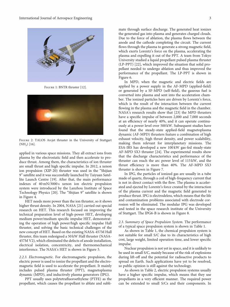
nozzle. Cassibry et al. [8] summarized the more than 50-year history of fusion propulsion research for deep spaceexploration, which suggests that magnetoinertial fusion canprovide the most economical approach rapid interplanetarytrip times. Borowski et al. [9, 10] summarized NASA’sresearch for over one year, which examined the feasibilityof the fission propulsion system in the exploration of humanextraterrestrial space. NASA designed a “two mode” thermo-nuclear rocket, bimodal nuclear thermal rocket (BNTR), topropel the vehicle to Callisto [11]. The fission reactor systemuses high-temperature uranium dioxide (UO2) in tungsten(W) metal matrix cermet fuel and advanced Brayton powerconversion technology to generate electricity [12]. In thisscheme, the full-automatic freight and oil tank trucks startfirst, and the track and ground resources are deployed inadvance before the crew gets on the Piloted Callisto TransferVehicle (PCTV) driven by artificial gravity. The BNTRthruster is shown in Figure 1.
2.2. Electric Propulsion. According to the different accelera-tion strategies, the electric propulsion systemmainly includesthe following three categories:
2.2.1. Electrothermal. For the electrothermal thruster, theelectric power is used to heat up the propellant whichexpands through a nozzle. Common propellants includehydrogen, xenon, hydrazine (N2H4), ammonia (NH3), andother anaerobic propellants. There are Resistojet and Arcjetunder the electrothermal subcategory. For Resistojet, thetemperature of the propellant is increased with an arc dis-charge. For Arcjet, it uses a combination of a heat exchangerconnected to a resistive heater element to heat up the propel-lant. According to the research of Wollenhaupt et al. [13],Arcjet requires a power between 0.3 and 100 kW generatingthrust between 200 and 7000mN with a higher Isp between200 and 2000 s. For instance, an Arcjet thruster developedby the University of Stuttgart [14, 15] uses hydrazine andammonia as propellants with a thrust of 100-500mN. Inaddition, the energy sources of the electrothermal thrusterinclude solar energy, laser, and microwave thermal energy,which are transmitted and concentrated in the heatexchanger or propellant itself, so as to heat it and spray itout. The Arcjet thruster is shown in Figure 2.
2.2.2. Electrostatic. For electrostatic thruster, the electricpower is used to ionize the propellant and the electrostaticfield is used to accelerate the propellant. The main typeincludes field emission electric propulsion (FEEP), ionthruster, and Hall-effect thruster (HET).
FEEP thrusters extract atoms and ions directly from themetal surface exposed to a vacuum by the electric field andaccelerate them. The propellant that produces thrust is usu-ally liquid metal. Using indium as the liquid metal ion source,Tajmar [17, 18] developed a special in-FEEP thruster. Thethruster is a micropulse device for a thrust of 1-100μN,which has low thrust noise and high resolution. The in-FEEP thruster is shown in Figure 3.
Ion propulsion and Hall-effect propulsion are currentlyrelatively successful thrusters, which have been tested and
2 International Journal of Aerospace Engineering
applied in various space missions. They all extract ions fromplasma by the electrostatic field and then accelerate to pro-duce thrust. Among them, the characteristics of ion thrusterare small thrust and high specific impulse. In 2012, a xenonion propulsion (XIP-20) thruster was used in the “Shijian9” satellite and it was successfully launched by Taiyuan Satel-lite Launch Centre [19]. After that, the main performanceindexes of 40mN/3000 s xenon ion electric propulsionsystem were introduced by the Lanzhou Institute of SpaceTechnology Physics [20]. The “Shijian 9” satellite is shownin Figure 4.
HET needs more power than the ion thruster, so it showshigher thrust density. In 2004, NASA [21] carried out specialresearch on HET. This research focused on improving thetechnical preparation level of high-power HET, developingmedium power/medium specific impulse HET, demonstrat-ing the operation of high power/high specific impulse Hallthruster, and solving the basic technical challenges of thenew concept of HET. Based on the existing NASA-457MHallthruster, this team redesigned a 50 kW Hall thruster (NASA-457MV2), which eliminated the defects of anode installation,electrical isolation, concentricity, and thermomechanicalinterference. The NASA’s HET is shown in Figure 5.
2.2.3. Electromagnetic. For electromagnetic propulsion, theelectric power is used to ionize the propellant and the electro-magnetic field is used to accelerate the propellant. It mainlyincludes pulsed plasma thruster (PPT), magnetoplasmadynamic (MPD), and inductively plasma generators (IPG).
PPT usually uses polytetrafluoroethylene (PTFE) as thepropellant, which causes the propellant to ablate and subli-
mate through surface discharge. The generated heat ionizesthe generated gas into plasma and generates charged clouds.Due to the force of ablation, the plasma flows between theanode and the cathode completing the circuit. The currentflows through the plasma to generate a strong magnetic field,which exerts Lorentz’s force on the plasma, accelerating theplasma and expelling it out of the PPT. A team from TokyoUniversity studied a liquid propellant pulsed plasma thruster(LP-PPT) [22], which improved the situation that solid pro-pellant needed to undergo ablation and thus improved theperformance of the propellant. The LP-PPT is shown inFigure 6.
In MPD, when the magnetic and electric fields areapplied by a power supply in the AF-MPD (applied-field)or generated by a SF-MPD (self-field), the gaseous fuel isconverted into plasma and sent into the acceleration cham-ber. The ionized particles here are driven by Lorentz’s force,which is the result of the interaction between the currentflowing in the plasma and the magnetic field in the chamber.NASA’s research results show that [23] the MPD thrustershave a specific impulse of between 2,000 and 7,000 secondsat an efficiency of nearly 40%, and it can operate continu-ously at a power level over 500 kW. Subsequent studies havefound that the steady-state applied-field magnetoplasmadynamic (AF-MPD) thrusters feature a combination of highexhaust velocity, high thrust density, and power scalability,making them relevant for interplanetary missions. TheESA-IRS has developed a new 100 kW gas-fed steady-stateAF-MPD SX3 thruster [24]. The experimental results showthat the discharge characteristics and performance of thethruster can reach the arc power level of 115 kW, and thethrust efficiency is more than 40%. The AF-MPD SX3thruster is shown in Figure 7.
In IPG, the particles of ionized gas are usually in a tubemade of quartz, through a coil of high-frequency current thatis not in direct contact with the flow. The plasma is acceler-ated and ejected by Lorentz’s force created by the interactionof the plasma current and the magnetic field generated toproduce thrust. IPG is electrodeless, which means that the lifeand contamination problems associated with electrode cor-rosion will be eliminated. The modular IPG was developedand tested in the space research institute of the Universityof Stuttgart. The IPG6-B is shown in Figure 8.
2.3. Summary of Space Propulsion System. The performanceof a typical space propulsion system is shown in Table 1.
As shown in Table 1, the chemical propulsion system isnot suitable for small S/C due to its characteristics of highcost, large weight, limited operation time, and lower specificimpulse.
Nuclear propulsion is not yet in space, and it is unlikely tobe used in small S/C, mainly because of the risk of explosionsduring lift-off and the potential for radioactive products tospread on Earth. Such applications have yet to be resolved,so public opinion is still against the technology.
As shown in Table 2, electric propulsion systems usuallyhave a higher specific impulse, which means that they usepropellants in a very efficient manner. The required powercan be extended to small S/Cs and their components. In
Figure 1: BNTR thruster [12].
Figure 2: TALOS Arcjet thruster in the University of Stuttgart(NH3) [16].
3International Journal of Aerospace Engineering

addition, its complexity is lower than that of chemical andnuclear propulsion systems. Therefore, the electric propul-sion system is selected as the main research object of ABEP.
3. Atmosphere-Breathing Electric Propulsion
The traditional electric propulsion system cannot guaranteethe long-time low-orbit operation of the S/C [31]. Due tothe constraints of propellant storage and thrust compensa-tion, the flight time usually does not exceed 2 years. ABEPis a technology that uses a thin atmosphere as a propellant
in low orbit without the need to carry any onboard propel-lant. And this system is generally composed of an inlet andan electric thruster. In addition, the technology can beapplied to planets with atmospheres, such as Mars [32],which allows S/C to perform longer missions at a new atmo-spheric altitude and is important for scientific research aswell as military and civilian monitoring services.
3.1. Air Intake of the ABEP System for LEO. The functions ofthe intake are of collecting the air while keeping its velocity,compressing it, and driving it into the thruster.
In 2003, the Japan Aerospace Exploration Agency(JAXA) [33, 34] designed air intake for the ABEP system.The air intake shows a honeycomb parallel straight pipeline,and the parallel gas flow has less collision with the intakewall. Thus, it has a high intake efficiency. In 2012, its study[35] showed that the intake design was sufficiently com-pressed to provide a pressure of 0.5 Pa to ignite the plasmainside the ECR at the orbital altitude of 200 km. The airintake of JAXA is shown in Figure 9.
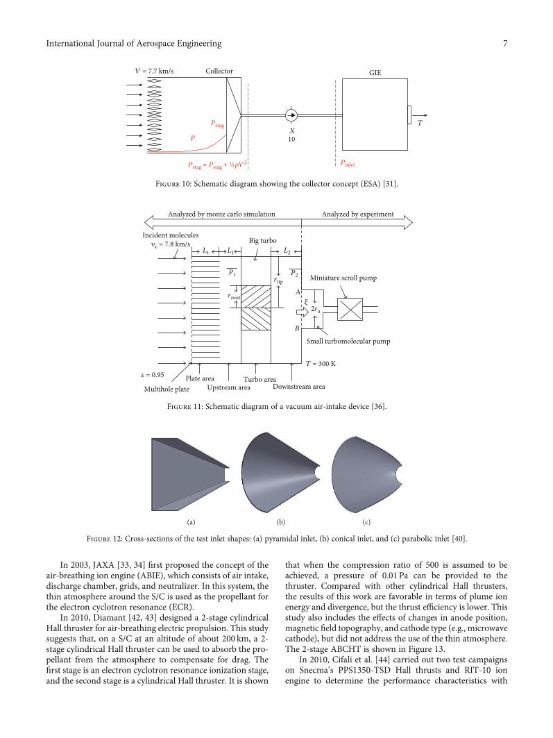
In 2007, the European Space Agency (ESA) [31] carriedout a feasibility analysis of the air-breathing electric propul-sion (RAM-EP) system. The proposed concept includes acollection system to capture thin airflow and a gridded ionengine (GIE) to generate the required thrust. The intake is
Ion beam
Extractor electrode
Taylor cone
Liquid metal pool
Needle
Jet
(a)
Module housing Heater element
Indium LMIS
(b)
Figure 3: In-FEEP thruster: (a) in-FEEP principle; (b) in-FEEP thruster consisting of indium LMIS, heater element, andmodule housing [18].
Figure 4: Xenon ion propulsion “Shijian 9” satellite [19].
Figure 5: NASA’s Hall-effect thruster: a solid model rendering ofNASA-457M V2 [21].
4 International Journal of Aerospace Engineering

positioned in the axial direction of the S/C and presents ahoneycomb shape, which can directly provide the requiredmass flow rate (MFR) to the thruster’s inlet at a certain pres-sure. The feasibility analysis shows that the RAM-EP concepthas great potential for low altitude and long lifetime missionsin the range of 200 to 250 km altitude. However, the results ofthe study are based on the prediction of thruster performancefor a given gas mixture using available theoretical models. Inorder to verify the performance prediction, the thruster of thenitrogen-oxygen mixture still needs to be tested and verified.The collector concept is shown in Figure 10.
In 2015, the Lanzhou Institute of Space TechnologyPhysics [36] designed and analysed an air-intake device for
atmosphere-breathing electric propulsion. The team carriedout a feasibility analysis of the air-breathing electric propul-sion system [37] and designed a vacuum intake device withan inlet diameter of 500mm, which was used to collect spacegas as the propellant of the air-breathing electric thruster. It iscomposed of a multihole plate, a large turbine, a small tur-bine molecular pump, and a miniature scroll pump in series.The intake device is shown in Figure 11.
In 2015, the team conducted design research on the airintake of the atmosphere-breathing electric propulsion sys-tem [38]. Compared with the research of JAXA and BUSEK,it is found that, ideally, the inflow should be as high as possi-ble and the backflow as low as possible in an air intake. It isrecommended to use a grid instead of a honeycomb structureat the front of the air intake to form a higher performance airintake.
In 2016, the team studied the transmission probability ofrarefied flows in low Earth orbit [39]. The results show thatthe collection efficiency (collected part of the flow into theair inlet) can be improved by implementing small ducts atthe front of the intake. The principle is a molecular trap thatallows most of the fast inflow passing through while reducingbackflow.
In 2018, Jackson and Marshall [40] tested three differentshapes of intake for their effectiveness in capturing incomingparticles: a pyramidal shape, a conical shape, and a parabolic
(a) (b)
Figure 6: LP-PPT of Tokyo University: (a) picture of a parallel plate LP-PPT; (b) streak photograph of parallel plate LP-PPT firing [22].
(a) (b)
Figure 7: AF-MPD SX3 thruster: (a) SX3 thruster after test campaign without SX coil (BN3); (b) mounted SX3 thruster and SX coilassembly [24].
Figure 8: IPG6-B in the University of Stuttgart [25].
5International Journal of Aerospace Engineering

shape. The results show that, under the ideal scenario of spec-ular reflection, the parabolic shape outperforms the other twoshapes due to the optics of a parabola and all particles willreflect toward the focus of the parabola. The test shapes areshown in Figure 12.
3.2. Electric Thruster for the ABEP System. The main electricthruster types for the ABEP system are electrothermal, electro-static, and electromagnetic. For electrothermal thrusters, com-
mon propellants include N2H4 and NH3. In the applicationbackground of ABEP, the high-temperature oxygen-containing environment may corrode the nozzles, resistors,and other components, so the electrothermal thrusters arenot suitable for atmosphere-breathing electric propulsion [41].
3.2.1. Electrostatic Thrusters. Electrostatic thrusters have themost extensive research on the concept of ABEP, includingIE and HET.
Table 1: Performance of space propulsion systems [26] p.11.
Space propulsion Specific impulse (s) Max. Δυ (km/s)∗ Max. thrust (N)
ChemicalSolid [7] 250~310 5.7~7.1 107
Liquid [7] 300~500 6.9~11.5 107
NuclearFission [9, 10] 500~800 11.5~20.7 106
Fusion [8, 27] 10,000~100,000 23~2,300 105
Electric
Electrothermal [13] 150~1,200 3.5~27.6 101
Electrostatic [16–20] 1,200~10,000 27.6~230 3×10⁻¹
Electromagnetic [28] 700~5,000 16.1~115 102
Propellantless Photon Rocket [29] 3 × 10⁷ Unlimited 10-4
∗Δυ (velocity difference) assuming S/C consists of 90% propellant.
Table 2: Performance of electric propulsion systems [26] p.76.
Electric propulsion Propellant Power (kW) Specific impulse (s) Efficiency (%) Thrust (mN)
ElectrothermalResistojet [30] N2H4, NH3 0.5~1.5 300 80 100~500Arcjet [13] N2H4, NH3 0.3~100 500~2k 35 200~7000
Electrostatic
FEEP [17, 18] In, Cs 0.01~0.15 8k~12k 30-90 0.001~1Ion [20] Xe 0.5~2.5 3k 60-80 100~200Hall [21] Xe, Kr, Ar 1.5~5 1.5k~2k 50 80~200
Electromagnetic
PPT [22] PTFE, Ar 0.001~0.2 1k 5 1~100MPD [23] NH3, H, Li 1~4000 2k~5k 25 1~200NIPG [25] N2, O2 0.5~3.5 — 46 —
Reflector
Air intake
(a)
Air intakeArea, 𝛼AAir leakage
Collimator (infinite conductance toinflow)
Reflector or diffuser0.04eV (diffusive)+ 4eV (mirror)
Exhaust velocity,V
Beam area, A
Air leakage
Air inflow
Air inflow
Orbital velocity 8 km/s= 5eV@atomic oxygen
V0
Large ECR ion engineMicrowave antenna
& grid support
Permanent magnets
Plasma
GridsSatelite cross
Sectional area, S
Air leakage Thermalized gas in the discharge chamberis hard to leak to upstream side through the collimator.
Ion beam N2+,O+, O2+, NO < 100 eV
(b)
Figure 9: Air intake of JAXA: (a) air intake; (b) operation principle of ABIE (without a neutralizer) [33].
6 International Journal of Aerospace Engineering
In 2003, JAXA [33, 34] first proposed the concept of theair-breathing ion engine (ABIE), which consists of air intake,discharge chamber, grids, and neutralizer. In this system, thethin atmosphere around the S/C is used as the propellant forthe electron cyclotron resonance (ECR).
In 2010, Diamant [42, 43] designed a 2-stage cylindricalHall thruster for air-breathing electric propulsion. This studysuggests that, on a S/C at an altitude of about 200 km, a 2-stage cylindrical Hall thruster can be used to absorb the pro-pellant from the atmosphere to compensate for drag. Thefirst stage is an electron cyclotron resonance ionization stage,and the second stage is a cylindrical Hall thruster. It is shown
that when the compression ratio of 500 is assumed to beachieved, a pressure of 0.01 Pa can be provided to thethruster. Compared with other cylindrical Hall thrusters,the results of this work are favorable in terms of plume ionenergy and divergence, but the thrust efficiency is lower. Thisstudy also includes the effects of changes in anode position,magnetic field topography, and cathode type (e.g., microwavecathode), but did not address the use of the thin atmosphere.The 2-stage ABCHT is shown in Figure 13.
In 2010, Cifali et al. [44] carried out two test campaignson Snecma’s PPS1350-TSD Hall thrusts and RIT-10 ionengine to determine the performance characteristics with
GIE
10X
T
Pinlet
Pstag
P
CollectorV = 7.7 km/s
Pstag = Pstag + ½𝜌V2
Figure 10: Schematic diagram showing the collector concept (ESA) [31].
Analyzed by monte carlo simulation Analyzed by experiment
Incident molecules𝜈c = 7.8 km/s Big turbo
Lt L1 L2
P2
2ra
A
B
rtip Miniature scroll pump
Small turbomolecular pump
rroot
P1
𝜉
T = 300 K
Turbo areaPlate areaUpstream area Downstream areaMultihole plate
𝜀 = 0.95
Figure 11: Schematic diagram of a vacuum air-intake device [36].
(a) (b) (c)
Figure 12: Cross-sections of the test inlet shapes: (a) pyramidal inlet, (b) conical inlet, and (c) parabolic inlet [40].
7International Journal of Aerospace Engineering

nitrogen and oxygen as propellants. The test results showthat the performance of both thrusters is obviously decreasedwith the propellant Xe, especially due to the low ionizationefficiency of atmospheric propellants. However, a long timeof ignition test indicates that both devices are basically ableto work continuously and steadily with such propellants.Furthermore, the measured performance is in the range ofRAM-EP applications. HET is preferred when a low power/-thrust ratio is required, and RIT is more appropriate when alow thrust level (less than 10mN) is required. The HET andRIT tests are shown in Figure 14.
In 2012, Pekker and Keidar [45] presented a model of air-breathing Hall-effect thruster. A new working method of air-breathing thruster is presented in which the inlet air is fullyionized without preliminary compression. It shows that, inthe case of 90-95 km orbit, the model can give 9.1-22mNthrust depending on the strength of magnetic field intensity.The estimation results show that the beam receiver on thespacecraft is not expected to generate a drag force larger thanthe thrust. However, this research considers a highly simpli-fied thruster model of the plasma-wall interaction inside thethruster chamber, and the Monte Carlo method should beused for more accurate simulation. The concept of ABHT isshown in Figure 15.
In 2012, BUSEK [32] developed a Martian Air-BreathingHall-Effect Thrust (MABHET) applied to S/C in the low orbitof Mars. It is also applied for corresponding patent [46]. This
system uses atmospheric gases as propellants, eliminating theneed to launch and carry propellants from the ground. Thethrust of a power peak ratio for an unmodified Hall thruster(designed to operate with xenon) has been measured, with aMars-like gas mixture, to be around 30mN/kW with a lowpeak of 19mN/kW with an efficiency of about 22-25%. TheMABHET of BUSEK is shown in Figure 16.
In 2012, Garrigues [47] carried out a computationalstudy on Hall-effect thrusters using the atmosphere as thepropellant. The possibility of using atmospheric gas as a pro-pellant for S/C in the Earth ionosphere is analysed by usingthe simple analytic scaling laws and the two-dimensionalhybrid model of the Hall-effect thruster. Compared to xenonpropellants, the length of the ionization layer increases due toa less favorable ionization cross-section in the atmosphere.As a result, the channel geometry and magnetic field strengthemployed by xenon are no longer suitable for low-mass pro-pellants. The analysis and calculation show that the decreaseof the magnetic field and the increase of channel length arebeneficial to the ionization of atmospheric gas. The calcula-tion also shows that the mass flow rate of the propellant isabout 3mg/s. For O and N, 20mN of thrust must be gener-ated to compensate for the resistance at an altitude of 250 km.
In 2013, Tagawa et al. [48] carried out an experimentalstudy on the air-breathing ion engine (ABIE) by using a laserdetonation beam source. The basic performance of ABIEusing upper atmospheric gases as a propellant was studied.
(a)
Windows
Electronextractionaperture
Vacuumbreak
PressuretripKeeper electrode
Contactring Sliding short
Magnet
1.58 (40)
0.250 (6.4)
Gas inlets
4.00 (102)
(b)
Figure 13: A 2 stage ABCHT: (a) ABCHT mounted to a vacuum chamber; (b) section view of cavity, dimensions in inches (mm) [43].
8 International Journal of Aerospace Engineering

The low-Earth-orbit environment of 140-200 km wassimulated by a laser detonation beam source, and the basicperformance of ABIE was studied by using a hyperthermalN2 beam. It was proposed that in an ABIE, hyperthermalN2 molecules were thermally heated by scattering on thereflecting surface. The efficiency of the collimator was exper-imentally investigated, and it was found that the collimatorcould maintain the N2 pressure inside the ABIE. The ionbeam current of 16mA at an acceleration voltage of 200Vprovided a thrust of 0.13mN for the hyperthermal N2 andatomic oxygen beams. It was also found that the maximumion beam was limited by the space charge effect. The experi-mental results strongly illustrated the composite action ofoxygen molecules in an ABIE. The ABIE concept is shownin Figure 17.
In 2017, Andreussi et al. [49] developed and tested theair-breathing Hall-effect thruster concept at SITAEL. Thissystem consists of a passive air intake/collector assemblyand an air-breathing double-stage Hall-effect thruster(RAM-HET). The former collects atmospheric molecules
and directs them to the thruster, while the latter enhancesthe ionization of the incoming flow by plasma confinementin the first stage and electrostatic acceleration in the secondstage. This test shows that the system can generate 6mNthrust when the airflow generated by the particle flow gener-ator (simulating the atmospheric flow characteristics corre-sponding to the altitude of 200 km) and the airflowcollected at the system inlet are run. However, this systemis currently unable to provide positive thrust due to the mea-surement of resistance of 26 ± 1mN. Andreussi’s RAM-HETis shown in Figure 18.
In 2018, Jackson and Marshall [40] studied anatmosphere-breathing ion thruster. This study mainlydesigned the inlet of the system, studied the capture efficiencyof particles and the ionization efficiency of atmospheric par-ticles, and then analysed the thrust force. The results showthat ionization efficiency is crucial to the thruster’s abilityto overcome low-Earth-orbit resistance. If the combined effi-ciency of the inlet and ionization is greater than or equal to
(a) (b)
(c) (d)
Figure 14: Two tests on HET and RIT: (a) the PPS1350-TSD; (b) HET operating with N2/O2 mixture; (c) 3D-CAD view of RIT-10EBB ionthruster; (d) RIT-10 thruster running with N2 [44].
Anode Magnetic poles Hollow cathode
Incomingambient
airPlume2rb
rb–ra
L
Figure 15: Schematic of atmosphere-breathing Hall thruster (not toscale) [45].
Flight direction
PayloadGas inlet
CompressionregionMABHET
Inlet
Figure 16: Conceptual MABHET of BUSEK [32].
9International Journal of Aerospace Engineering

9%, the 3U version of the system can only compensate forthe resistance of approximately 300 km. If the combinedefficiency of the inlet and ionization is maintained at approx-imately 5% or more, 6U, 12U, and 27U system configura-tions can compensate for the resistance of 200 km. Whenthe ionization efficiency is 50%, the resistance of the 6U sys-tem of 200 km matches the intake efficiency of 10%, and theperformance will be greatly improved. Jackson’s ABIT isshown in Figure 19.
3.2.2. Electromagnetic Thrusters. Researches about electro-magnetic thrusters for the ABEP concept are rarely less,including PPT, MPD, and IPG.
In 2013, Greig et al. [50] studied an atmospheric plasmathruster (APT). Using direct force measurements and parti-cle image velocimetry, an unparallel angular actuator withan exposed electrode and a closed electrode was investigated.It was shown that the induced force increased nonlinearly byincreasing the included angle. In addition, the direction ofthe upstream component of the ion wind was varied bychanging the electrode angle. Changing the angle betweenthe electrodes can change the strength of the electric fieldnear the plasma driver, which in turn changes the response.
Then, using the experimental results, a concept of atmo-spheric plasma thrust was designed as a dielectric barrierdischarge plasma actuator. The APT products are shown inFigure 20.
In 2013, Shabshelowitz [51] studied the radio-frequencyplasma technology for the ABEP system in his doctoral the-sis. According to the requirements of the system, two novelthrusters were tested in the laboratory. The first thruster usedonly radio frequency and magnetic fields to generate thrust.The second was a two-stage thruster using a radio-frequency ionization level to improve the propellant utiliza-tion efficiency of traditional thruster. Measurements ofthruster performance were presented against the backgroundof atmosphere breathing, as well as plasma probe exhaustmeasurements to characterize the major loss mechanisms.The results showed that the air-breathing S/C was feasibleunder the condition of the existing technology. The RF-ABEP is shown in Figure 21.
In 2014, Johnson et al. [52] studied a pulsed plasmathruster (PPT) for atmospheric operation. Coaxial PPTs withdifferent sizes of electrodes were tested under the backgroundpressure of 10-40Torr. The resulting specific thrust wasdefined as the impulse measured on the thrust stand
10-inch flange
To TOFNozzle
PSV
Laser
N2 gas
MirrorTo pump
ABIE
(a) (b)
Figure 17: ABIE concept: (a) schematics and a photograph of the laser detonation atomic beam source; (b) photograph of oxygen plasmaobserved from the front side of the ABIE [48].
(a) (b)
Figure 18: Andreussi’s RAM-HET: (a) view of the intake/collector assembly reduced scale mode; (b) HT5k firing with 1.27N2+O2mixture [49].
10 International Journal of Aerospace Engineering

normalized by the capacitor energy, which was proportionalto the background pressure and discharge chamber volume,and inversely proportional to the capacitor energy. Currentand voltage measurements showed no difference in the dis-charge between atmospheric and vacuum operations, whilehigh-speed camera imaging showed that the accelerationmechanism of atmospheric operations was entirely electro-thermal, compared to the mixed thermal and magnetic accel-eration under vacuum pressure. To demonstrate thatatmosphere-breathing PPT was a viable concept, the devicewas launched from a high-altitude burst balloon at an alti-tude of 31.9 km. Johnson’s AB-PPT is shown in Figure 22.
In 2017, Göksel and Mashek [53] demonstrated that thefirst critical test of the future air-breathing magnetoplasmapropulsion system (MPP) had been successfully completed.In this regard, it was also the first time that a pinching dense
plasma focus discharge could be ignited at one atmosphereand driven using a very fast nanosecond electrostatic excita-tion in pulse mode to induce a self-organizing plasma chan-nel for propelling the master discharge ignition. According tothe capacitor voltage (200-600 v), the energy input in oneatmosphere varied from 52 to 320 J/pulse, corresponding tothe pulse potential of 1.2-8.0mNs. This new pulsed plasmapropulsion system, driven by 1000 pulses per second, alreadyhad the thrust area ratio (50-150 kn/m2) of a modern jetengine. Göksel’s AB-MPP is shown in Figure 23.
In 2013, the University of Tokyo and the University ofStuttgart jointly conducted research on the air-breathingelectric thruster [41, 54]. Preliminary studies have shownthat the propellant flow required for electrostatic propulsionof the near-Earth altitude exceeds the possible mass intake,and that electrode corrosion due to oxygen flow may limit
Inlet
Ionization
1U 1U 1U
Ion containmentregion
Accelerator grids
(a)
(b)
Figure 19: Jackson’s ABIT: (a) representations of the cross-section of the proposed system; (b) mockup of the 6U sized thruster system [40].
(a) (b)
Figure 20: APT products: (a) experimental rig and balance; (b) computer model of plasma thruster prototype [50].
11International Journal of Aerospace Engineering

the life of the propulsion system. However, pulsed plasmathrusters (PPT) can operate successfully with low massintake and relatively low power. This makes it an interestingcandidate for low-orbit air-breathing applications. The anal-ysis of this atmosphere-breathing PPT system shows that inthe altitude range of 150-250 km, a thrust power ratio of30mN/kW and a specific impulse of 5000 s are at least par-tially feasible for the resistance compensation. In addition,in order to avoid electrode ablation, induction heating elec-trothermal plasma generator technology is also discussed toobtain a possible propulsion system that can handle gaseouspropellants without adverse side effects. Current technologycan be used to generate a thrust of about 4.4mM per 1mg/smass flow, which is sufficient to compensate for the drag ofsmall satellites at the altitude of 150-250 km.
The coaxial air-fed pulsed plasma thruster was furtherdeveloped by the cooperative team in 2018 [55]. Potentialdesign improvements in electrode geometry and propellantinjection were derived from the experimental results of theearly air-fed PPT prototype and applied to the design of thenext generation of coaxial air-fed PPT. This latest studyexamines the effectiveness of design changes on performanceand electrode corrosion, which will be a strong indicator oflifetime assessment. The results show that the electrode abla-tion degree of air-fed PPT is higher than that of a typical gas-fed thruster. The VIPER concept is shown in Figure 24.
Starting from 2013, a team in the University of Stuttgartdeveloped and tested a new design of an inductively drivenplasma generator (IPG) [25]. This new IPG makes it possible
to produce a nonpolar high enthalpy plasma and gives the ini-tial characterization results of air plasma. It is shown that themass-specific enthalpies of air plasma are more than 10MJ/kg.
In 2017, the team conducted a performance evaluation ofa novel inductive atmosphere-breathing EP system [56]. Thefacility uses IPG6-S, a small-scale IPG with an input power ofup to 3.5 kW. The device allows for more reliable test condi-tions. The operation and performance of IPG6-S were testedfor the first time. IPG6-S is a test bed for the development ofan induced plasma thruster (IPT) for ABEP application.
In 2018, the team analysed the electrodeless plasma sourceenhancement by an externally applied magnetic field for aninduced plasma thruster (IPT) [57, 58]. The plasma resistanceand density characteristics of magnetized and unmagnetizedplasma source were studied for different frequencies, inputpower, magnetic field intensity, pressure, temperature, plasmadensity profile, discharge channel, and antenna sizes. In 2019,the team also carried out experimental tests on the system[56–58] and carried out detailed design and verification ofthe IPT system. The IPT system is shown in Figure 25.
In 2020, this team deals in particular with the design andimplementation of a novel antenna called the birdcageantenna [59]. It can be employed for helicon-wave-basedplasma sources in fusion research. It uses antenna resonancefor the additional acceleration of both ions and electrons viaE × B forces. Correspondingly, the system benefits not onlyfrom the electrodeless design enabling a maximum variabilityof both composition and density but also from the quasineu-tral plasma jet such that a neutralizer is not needed.
Payload bay
Inlet
Propulsion systemCompressor
Propellant tank
(a) (b)
Figure 21: RF-ABEP: (a) cross-section of a notional atmosphere-breathing spacecraft; (b) single-stage Helicon Hall Thruster (HHT)operation with nitrogen propellants [51].
(a) (b)
Figure 22: Johnson’s AB-PPT: (a) the four PPTs tested with different diameters; (b) 62 J plume images at 50μTorr, 0-40 μs after igniterdischarge [52].
12 International Journal of Aerospace Engineering

In 2019, the Beijing Institute of Spacecraft EnvironmentEngineering [61, 62] carried out a concept study of air-breathing helicon thruster (ABHT) used in ultra-low-orbit
flight. A contractive-shaped air inlet channel compacts welldirectly with an electrodeless helicon wave discharge tube.A predischarge sheath is set up in the rear port of the
Bar anode
Cathode
Discharge current
Lorentz force
Ion velocity
Bar anode
BB
B
B
BB
(a)
(b)
Figure 23: Göksel’s AB-MPP: (a) physical principle of magnetoplasma compressors (MPC); (b) photos of transient atmospheric nanosecondpulse discharges for internal MPC excitation [53].
Plasma
Inductioncoil
243
Injector Water-cooled casing Closure
40 160Gas
injection
(a) (b)
Figure 24: Variable Inlet feeding atmosphere-breathing PPT for Electrode eRo-sion measurements (VIPER): (a) schematic of VIPER inradial-injection configuration; (b) VIPER in operation [55].
13International Journal of Aerospace Engineering
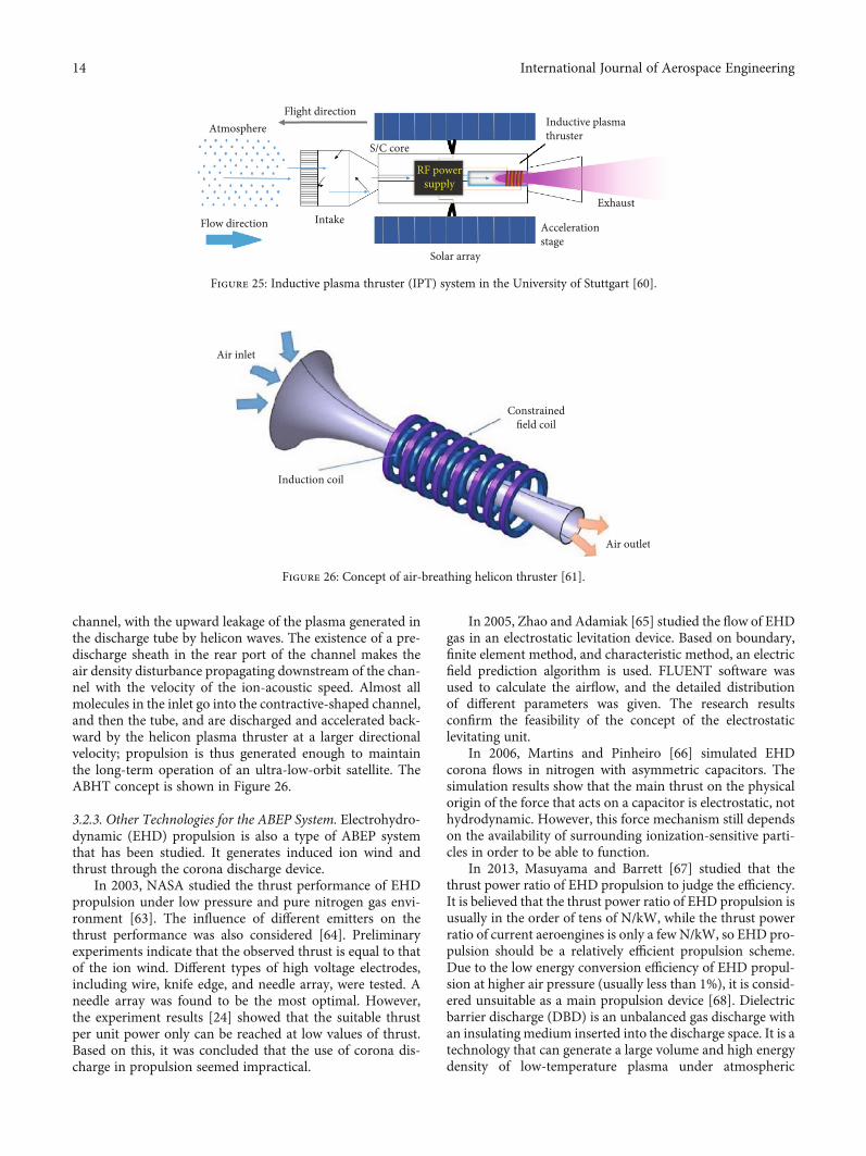
channel, with the upward leakage of the plasma generated inthe discharge tube by helicon waves. The existence of a pre-discharge sheath in the rear port of the channel makes theair density disturbance propagating downstream of the chan-nel with the velocity of the ion-acoustic speed. Almost allmolecules in the inlet go into the contractive-shaped channel,and then the tube, and are discharged and accelerated back-ward by the helicon plasma thruster at a larger directionalvelocity; propulsion is thus generated enough to maintainthe long-term operation of an ultra-low-orbit satellite. TheABHT concept is shown in Figure 26.
3.2.3. Other Technologies for the ABEP System. Electrohydro-dynamic (EHD) propulsion is also a type of ABEP systemthat has been studied. It generates induced ion wind andthrust through the corona discharge device.
In 2003, NASA studied the thrust performance of EHDpropulsion under low pressure and pure nitrogen gas envi-ronment [63]. The influence of different emitters on thethrust performance was also considered [64]. Preliminaryexperiments indicate that the observed thrust is equal to thatof the ion wind. Different types of high voltage electrodes,including wire, knife edge, and needle array, were tested. Aneedle array was found to be the most optimal. However,the experiment results [24] showed that the suitable thrustper unit power only can be reached at low values of thrust.Based on this, it was concluded that the use of corona dis-charge in propulsion seemed impractical.
In 2005, Zhao and Adamiak [65] studied the flow of EHDgas in an electrostatic levitation device. Based on boundary,finite element method, and characteristic method, an electricfield prediction algorithm is used. FLUENT software wasused to calculate the airflow, and the detailed distributionof different parameters was given. The research resultsconfirm the feasibility of the concept of the electrostaticlevitating unit.
In 2006, Martins and Pinheiro [66] simulated EHDcorona flows in nitrogen with asymmetric capacitors. Thesimulation results show that the main thrust on the physicalorigin of the force that acts on a capacitor is electrostatic, nothydrodynamic. However, this force mechanism still dependson the availability of surrounding ionization-sensitive parti-cles in order to be able to function.
In 2013, Masuyama and Barrett [67] studied that thethrust power ratio of EHD propulsion to judge the efficiency.It is believed that the thrust power ratio of EHD propulsion isusually in the order of tens of N/kW, while the thrust powerratio of current aeroengines is only a few N/kW, so EHD pro-pulsion should be a relatively efficient propulsion scheme.Due to the low energy conversion efficiency of EHD propul-sion at higher air pressure (usually less than 1%), it is consid-ered unsuitable as a main propulsion device [68]. Dielectricbarrier discharge (DBD) is an unbalanced gas discharge withan insulating medium inserted into the discharge space. It is atechnology that can generate a large volume and high energydensity of low-temperature plasma under atmospheric
Flight directionAtmosphere
Flow direction Intake
Solar array
Accelerationstage
Exhaust
S/C core
RF powersupply
Inductive plasmathruster
Figure 25: Inductive plasma thruster (IPT) system in the University of Stuttgart [60].
Air inlet
Constrainedfield coil
Induction coil
Air outlet
Figure 26: Concept of air-breathing helicon thruster [61].
14 International Journal of Aerospace Engineering

pressure. In 2016, Chen [69] introduced an air-breathingelectric propulsion technology for near-space vehicles. Thistechnique uses the single dielectric barrier discharge (SDBD)as the plasma source, which can ionize the atmosphere toproduce plasma and generate thrust in a wide range of atmo-spheric pressure. The test results show that the thrust force of102-103μN can be generated when the atmospheric pressureis 10-90 kPa, and the thrust force is related to the power of thedriving voltage. Chen’s products are shown in Figure 27.
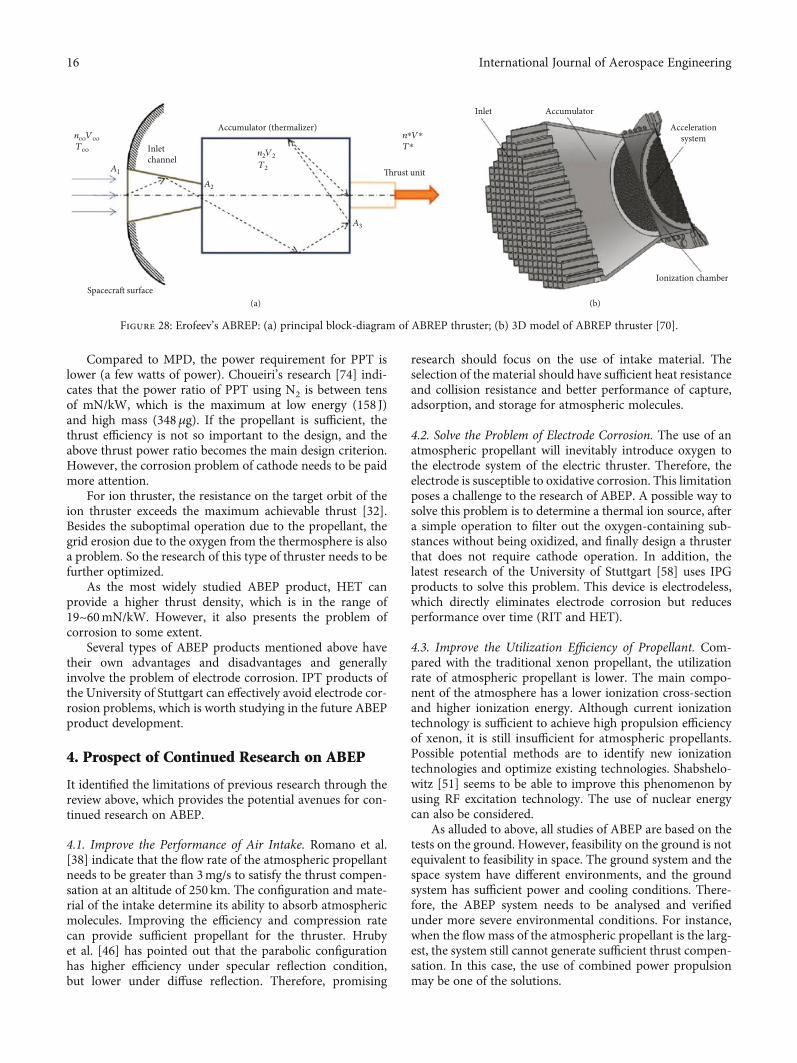
In 2017, Erofeev et al. [70] designed an accumulator forair-breathing ramjet electric propulsion (ABREP) system.As shown in Figure 28, the inlet channel is intended forreceiving the incoming atmospheric particle flow and itshould prevent particles leaving the accumulator under freemolecular motion. The accumulator is a chamber for flowdeceleration. Its main function is to “maxwellize” (or ther-malize) particles of the incoming gas flow. The accumulatorcan make it possible to maintain the gas density needed forthe operation of the ramjet thruster in the ionization regionin the thrust unit.
3.3. Discussion about the ABEP System. According to theprevious studies, it can be found that the types ofatmosphere-breathing electric propulsion mainly includepulsed plasma thruster (PPT), magnetoplasma dynamic(MPD) thruster, ion engine (IE), and Hall-effect thruster(HET). As shown in Table 3, a comparative analysis of differ-ent ABEP products/concepts is listed, which is in terms ofmass, frontal area, altitude, lifetime, thrust, power density,efficiency, and so on.
The mass of the ABEP device is basically less than1000 kg, which directly determines the launch cost. Thecross-sectional area of the intake device is about 0.2 m2,which determines the atmospheric absorption capacity ofthe device. The work altitude of S/C is generally lower than250 km, which determines the resistance compensationrequired by the thruster. The system is potentially interest-ing for low altitude and long lifetime missions, which islower than 250 km and in the range of 3~8years. The powerdensity is about 10~59mN/kW, which can produce effectivethrust. In the previous studies, MPD, PPT, IE, and HET havebeen considered.
For electrothermal thrusters, common propellants areusually oxygen-free and the high-temperature oxygen-containing environment may corrode the nozzles, resistors,and other components in particular for Arcjets, so a newelectrode technology needs to be developed. Arcjets with anadvanced electrode technology could be relevant for thehigh-power regime. In addition, Resistojets are flexible buttoo low Isp. Therefore, the electrothermal thrusters are notsuitable for atmosphere-breathing electric propulsion cur-rently [41].
For MPD, the corrosion of the electrode system is one ofthe most important problems in the product application.Future atmosphere-breathing MPD needs 103 ignitions persecond [53]. Therefore, alternative materials for amorphousmetals and special alloys with different porosity and surfacestructure will be studied in the future. In addition, the neces-sary mass flow rates for thruster might be too high for theABEP application [41].
Test prototype
Microthrusttest bench
Motion detector
(a)
ThrustCalibration
device
Thruster
Balance
Motiondetector
Counterweight
(b)
Figure 27: Chen’s prototype and test bench: (a) test prototype; (b) test bench of microthrust [69].
15International Journal of Aerospace Engineering
Compared to MPD, the power requirement for PPT islower (a few watts of power). Choueiri’s research [74] indi-cates that the power ratio of PPT using N2 is between tensof mN/kW, which is the maximum at low energy (158 J)and high mass (348μg). If the propellant is sufficient, thethrust efficiency is not so important to the design, and theabove thrust power ratio becomes the main design criterion.However, the corrosion problem of cathode needs to be paidmore attention.
For ion thruster, the resistance on the target orbit of theion thruster exceeds the maximum achievable thrust [32].Besides the suboptimal operation due to the propellant, thegrid erosion due to the oxygen from the thermosphere is alsoa problem. So the research of this type of thruster needs to befurther optimized.
As the most widely studied ABEP product, HET canprovide a higher thrust density, which is in the range of19~60mN/kW. However, it also presents the problem ofcorrosion to some extent.
Several types of ABEP products mentioned above havetheir own advantages and disadvantages and generallyinvolve the problem of electrode corrosion. IPT products ofthe University of Stuttgart can effectively avoid electrode cor-rosion problems, which is worth studying in the future ABEPproduct development.
4. Prospect of Continued Research on ABEP
It identified the limitations of previous research through thereview above, which provides the potential avenues for con-tinued research on ABEP.
4.1. Improve the Performance of Air Intake. Romano et al.[38] indicate that the flow rate of the atmospheric propellantneeds to be greater than 3mg/s to satisfy the thrust compen-sation at an altitude of 250 km. The configuration and mate-rial of the intake determine its ability to absorb atmosphericmolecules. Improving the efficiency and compression ratecan provide sufficient propellant for the thruster. Hrubyet al. [46] has pointed out that the parabolic configurationhas higher efficiency under specular reflection condition,but lower under diffuse reflection. Therefore, promising
research should focus on the use of intake material. Theselection of the material should have sufficient heat resistanceand collision resistance and better performance of capture,adsorption, and storage for atmospheric molecules.
4.2. Solve the Problem of Electrode Corrosion. The use of anatmospheric propellant will inevitably introduce oxygen tothe electrode system of the electric thruster. Therefore, theelectrode is susceptible to oxidative corrosion. This limitationposes a challenge to the research of ABEP. A possible way tosolve this problem is to determine a thermal ion source, aftera simple operation to filter out the oxygen-containing sub-stances without being oxidized, and finally design a thrusterthat does not require cathode operation. In addition, thelatest research of the University of Stuttgart [58] uses IPGproducts to solve this problem. This device is electrodeless,which directly eliminates electrode corrosion but reducesperformance over time (RIT and HET).
4.3. Improve the Utilization Efficiency of Propellant. Com-pared with the traditional xenon propellant, the utilizationrate of atmospheric propellant is lower. The main compo-nent of the atmosphere has a lower ionization cross-sectionand higher ionization energy. Although current ionizationtechnology is sufficient to achieve high propulsion efficiencyof xenon, it is still insufficient for atmospheric propellants.Possible potential methods are to identify new ionizationtechnologies and optimize existing technologies. Shabshelo-witz [51] seems to be able to improve this phenomenon byusing RF excitation technology. The use of nuclear energycan also be considered.
As alluded to above, all studies of ABEP are based on thetests on the ground. However, feasibility on the ground is notequivalent to feasibility in space. The ground system and thespace system have different environments, and the groundsystem has sufficient power and cooling conditions. There-fore, the ABEP system needs to be analysed and verifiedunder more severe environmental conditions. For instance,when the flow mass of the atmospheric propellant is the larg-est, the system still cannot generate sufficient thrust compen-sation. In this case, the use of combined power propulsionmay be one of the solutions.
Figure 28: Erofeev’s ABREP: (a) principal block-diagram of ABREP thruster; (b) 3D model of ABREP thruster [70].
16 International Journal of Aerospace Engineering

Table3:Com
parisonof
previous
stud
iesabou
tABEPsystem
s.
Thruster
Reference
S/C
mass
(kg)
Crossarea
ofS/C(m
2 )
Areaof
intake
(m2 )
Dam
ping
coeffi
cient
(Cd)
Length
ofcollector
(m)
Inlet
pressure
(Pa)
Orbit
altitude
(km)
Lifetime
(years)
Thrust
(mN)
Pow
er(kW)
Pow
erdensity
(mN/kW)
Efficiency
(%)
GIE
ESA
[31]
1000
10.15~0
.62.0
0.2~
1.3
10-3
200~
250
3~8
2~20
1
MABHET
BUSE
K[32]
0.3
0.15
3.0
19~3
035
ABIE
JAXA[33,34]
1.5
0.48
2.0
0.5±
200±
>23.3+
10~1
4
Intake
Lanzho
uISTP[36]
>5.7
d=0:5m
0.3-
150~
240
41~5
7
ABIT
Jacksonand
Marshall[40]
50~1
000.01
2.2
0.05~0
.1>8
010
2-stage
HET
Diamant[42,43]
0.5
0.25
2.2
0.01
200
135
HET
Cifalietal.[44]
19~2
41.4
RIT-10
Cifalietal.[44]
5.25-6
0.45
HET
PekkerandKeidar
[45]
90~9
59.1~
22N
700~
2000
13
HET
Garrigues
[47]
12.0
10-3
250
201
10
ABIE
Tagaw
aetal.[48]
0.15
140-200
0.13
HET
And
reussietal.[49]
50d=0:5m
0.126~
12-3
1.0
200
62.4
28~3
2
RF-HET
Shabshelow
itz[51]
325
0.39
2-4
2.1
200
30.306
29-59
90
PPT
John
sonetal.[52]
200.05
22-40
57.5+
MPD
Gökseland
Mashek
[53]
202N
75
PPT
Schö
nherretal.[41,
54,55]
0.3
10-3
200
4.4
20~3
0
IPT
Rom
anoetal.[38,
56,58–60,71–73]
0.3~
10.3-3
120
5~250
0.5-3.5
25
17International Journal of Aerospace Engineering

5. Conclusion
In this paper, the great advantage of the ABEP application isintroduced. Using atmospheric molecules as the propellanthas great economic value, effectively reducing the weight ofthe propellant carried and extending the lifetime of S/C.
The main space propulsion systems are compared firstly,and the results show that the electric propulsion system maybe the best selection for ABEP products for its higher specificimpulse and more efficient structures.
This review has also introduced the previous studies ofresearchers about ABEP systems, which mainly includepulsed plasma thruster (PPT), magnetoplasma dynamic(MPD) thruster, ion engine (IE), and Hall-effect thruster(HET). The main performance of different ABEP conceptsis summarized in Table 3, and their limitations are alsopointed out. The corrosion problem of cathode or grid needsto be paid more attention for PPT, MPD, and IE. In addition,HET and ion thrusters need a neutralizer, and they cannot beoperated with thermospheric gases.
The potential avenues to develop the further ABEP prod-ucts are introduced in the last, which focus on the air intakeefficiency, the corrosion phenomenon, and the utilizationefficiency.
As a result of an increasing interest to study the spaceand the great potential to operate satellites at low Earthorbit, the concept of ABEP is promising but the applica-tion of this concept requires further development. Byunderstanding previous studies in this paper, researcherscan continue to develop ABEP technology into a fieldabletechnology.
Abbreviations
ABCHT: Air-breathing cylindrical Hall thrusterABEP: Atmosphere-breathing electric propulsionABHT: Air-breathing helicon thrusterABIE: Air-breathing ion engineABREP: Air-breathing ramjet electric propulsionAF: Applied-fieldAPT: Atmospheric plasma thrusterBNTR: Bimodal nuclear thermal rocketDBD: Dielectric barrier dischargeECR: Electron cyclotron resonanceEHD: ElectrohydrodynamicESA: Europe Space AgencyFEEP: Field emission electric propulsionHET: Hall-effect thrusterIE: Ion engineIPG: Inductively plasma generatorsIPT: Induced plasma thrusterIRS: Institute of Space SystemJAXA: Japan Aerospace Exploration AgencyLEO: Low earth orbitLP: Liquid propellantMABHET: Martian air-breathing Hall-effect thrustMFR: Mass flow rateMPD: Magneto plasma dynamicMPP: Magneto plasma propulsion
NASA: National Aeronautics and Space AdministrationPCTV: Piloted Callisto transfer vehiclePPT: Pulsed plasma thrusterPTFE: PolytetrafluoroethyleneRAM-EP: Air-breathing electric propulsionRF: Radio frequencyRIT: Radio-frequency ion thrusterS/C: SpacecraftsSDBD: Single dielectric barrier dischargeSF: Self-fieldVIPER: Variable Inlet feeding air-breathing PPT for
Electrode eRo-sion measurementsXIP: Xenon ion propulsion.
Data Availability
The numerical data used to support the findings of this studyare included within the article.
Conflicts of Interest
The authors declare that there are no conflicts of interestregarding the publication of this paper.
Acknowledgments
Peng Zheng would like to thank Mengjie Zhao for hersupport. This study was funded by the National NaturalScience Foundation of China (grant number 11772354) andthe Postgraduate Research and Innovation Project of Hunan(grant number CX20190053).
References
[1] J. Y. Tong and S. H. Xiang, “Near space environment and envi-ronment tests,” Equipment Environment Engineering, vol. 3,pp. 1–4, 2012.
[2] Y. K. Wang, “An analysis on application prospects and devel-opment of near-space vehicles,” National Défense Technology,vol. 2, pp. 20–24, 2009.
[3] N. H. Crisp, P. C. E. Roberts, S. Livadiotti et al., “The benefitsof very low earth orbit for earth observation missions,” Prog-ress in Aerospace Sciences, vol. 117, p. 100619, 2020.
[4] T. Romano, A. Boxberger, S. Fasoulas et al., “Attitude controlfor satellites flying in VLEO using aerodynamic surfaces,”Journal of the British Interplanetary Society, vol. 73, pp. 103–112, 2020.
[5] C. Traub, F. Romano, T. Binder et al., “On the exploitation ofdifferential aerodynamic lift and drag as a means to controlsatellite formation flight,” CEAS Space Journal, vol. 12, no. 1,pp. 15–32, 2020.
[6] P. Chen, Z. W. Wu, X. Y. Liu, K. Xie, and N. F. Wang, “An air-breathing electric thruster for near-space vehicle,” Journal ofAstronautics, vol. 2, pp. 203–208, 2016.
[7] C. K. Law, “Fuel options for next-generation chemical propul-sion,” AIAA Journal, vol. 50, no. 1, pp. 19–36, 2012.
[8] J. Cassibry, R. Cortez, M. Stanic, A. Watts, W. Seidler, andR. Adams, “Case and development path for fusion propul-sion,” Journal of Spacecraft and Rockets, vol. 52, pp. 595–612,2015.
18 International Journal of Aerospace Engineering

[9] S. Borowski, L. Dudzinski, and M. McGuire, “Bimodalnuclear thermal rocket(NTR) propulsion for power-rich,artificial gravity human exploration missions to Mars,” inIAF, International Astronautical Congress, 52nd, Toulouse,France, 2001.
[10] S. K. Borowski, M. L. McGuire, L. M. Mason, J. H. Gilland,and T. W. Packard, “"Bimodal" nuclear thermal rocket(BNTR) propulsion for an artificial gravity HOPE Missionto Callisto,” in In AIP Conference Proceedings, pp. 829–836, 2003.
[11] P. A. Troutman, K. Bethke, F. Stillwagen et al., “Revolutionaryconcepts for human outer planet exploration (HOPE),” in AIPConference Proceedings, 2003, pp. 821–828, 2003.
[12] M. L. McGuire, S. K. Borowski, L. M. Mason, and J. Gilland,“High power MPD nuclear electric propulsion (NEP) for artifi-cial gravity HOPE missions to Callisto,” in AIP Conference Pro-ceedings, 2003, https://ntrs.nasa.gov/citations/20040005901.
[13] B. Wollenhaupt, Q. H. Le, and G. Herdrich, “Overview of ther-mal arcjet thruster development,” Aircraft Engineering andAerospace Technology, vol. 90, no. 2, pp. 280–301, 2018.
[14] M. Auweter-Kurtz, B. Glocker, T. Golz et al., “Arcjet thrusterdevelopment,” Journal of Propulsion and Power, vol. 12,no. 6, pp. 1077–1083, 1996.
[15] T. D. Schmidt, Bemannte missionen zumMars mit kontinuier-lichen antrieben, M.S Thesis, Insitute of Space Systems (IRS),Stuttgart, 2005.
[16] I. U. Stuttgart, “Elektrische Raumfahrtantriebe - UniversitätStuttgart,” August 2012, http://www.irs.uni-stuttgart.de/forschung/elektrische_raumfahrtantriebe/index-alt.en.html.
[17] M. Tajmar and J. Wang, “Three-dimensional numericalsimulation of field-emission-electric-propulsion neutraliza-tion,” Journal of Propulsion and Power, vol. 16, pp. 536–544, 2000.
[18] M. Tajmar, A. Genovese, and W. Steiger, “Indium field emis-sion electric propulsion microthruster experimental character-ization,” Journal of Propulsion and Power, vol. 20, pp. 211–218,2004.
[19] C. Yun, “Practice the successful formation flying of No. 9 sat-ellite,” Satellite Applications, vol. 6, p. 67, 2012.
[20] X. Y. Wang, T. P. Zhang, H. C. Jiang, S. Wang, and J. Gao, “In-orbit test and analysis of working performance for 40mN/3000s xenon ion electric propulsion system,” Journal ofRocket Propulsion, vol. 1, pp. 76–81, 2015.
[21] D. Jacobson, D. Manzella, R. Hofer, and P. Peterson, “NASA's2004 Hall thruster program,” in 40th AIAA/ASME/SAE/ASEEJoint Propulsion Conference and Exhibit, 2004, Fort Lauder-dale, Florida, 2004.
[22] H. Koizumi, A. Kakami, Y. Furuta, K. Komurasaki, andY. Arakawa, “Liquid propellant pulsed plasma thruster,” inProceedings of 28th International Electric Propulsion Confer-ence, Toulouse, France, 2003, Toulouse, France, 2003.
[23] R. Myers, M. Lapointe, and M. Mantenieks, “MPD thrustertechnology,” in Conference on Advanced SEI Technologies,1991, p. 3568, Cleveland, OH, USA, 1991.
[24] A. Boxberger and G. Herdrich, “Integral measurements of 100kW class steady state applied-field magnetoplasmadynamicthruster SX3 and perspectives of AF-MPD technology,” in35th International Electric Propulsion Conference, GeorgiaInstitute of Technology, pp. 8–12, USA, 2017.
[25] M. Dropmann, G. Herdrich, R. Laufer et al., “A new induc-tively driven plasma generator (IPG6)—setup and initial
experiments,” IEEE Transactions on Plasma Science, vol. 41,no. 4, pp. 804–810, 2013.
[26] M. Tajmar, Advanced Space Propulsion Systems, Springer Sci-ence & Business Media, 2012.
[27] R. A. Gabrielli, D. Petkow, G. Herdrich, R. Laufer, and H. P.Röser, “Two generic concepts for space propulsion based onthermal nuclear fusion,” Acta Astronautica, vol. 101,pp. 129–137, 2014.
[28] G. Herdrich, U. Bauder, A. Boxberger et al., “Advanced plasma(propulsion) concepts at IRS,” Vacuum, vol. 88, pp. 36–41,2013.
[29] E. G. Haug, “The ultimate limits of the relativistic rocket equa-tion. The Planck photon rocket,” Acta Astronautica, vol. 136,pp. 144–147, 2017.
[30] I. Coxhill and D. Gibbon, “A xenon resistojet propulsionsystem for microsatellites,” in 41st AIAA/ASME/SAE/ASEEJoint Propulsion Conference & Exhibit, Tucson, Arizona,July 2005.
[31] D. Di Cara, J. Gonzalez Del Amo, A. Santovincenzo et al.,“RAM electric propulsion for low earth orbit operation: anESA study,” in 30th International Electric Propulsion Confer-ence, Florence, Italy, 2007.
[32] K. Hohman, Atmospheric breathing electric thruster for plane-tary exploration, Busek Co, 2012.
[33] K. Nishiyama, “Air breathing ion engine concept,” in 54thInternational Astronautical Congress of the InternationalAstronautical Federation, the International Academy of Astro-nautics, and the International Institute of Space Law, 2003,Bremen, Germany, 2003.
[34] K. Fujita, “Air intake performance of air breathing ionengines,” Japan Society of Aeronautical Space Sciences,vol. 52, pp. 514–521, 2005.
[35] Y. Hisamoto, K. Nishiyama, and H. Kuninaka, “Design of airintake for air breathing ion engine,” in 63rd InternationalAstronautical Congress, Naples, Italy, 2012.
[36] Y. Li, X. Chen, D. Li, Y. Xiao, P. Dai, and C. Gong, “Designand analysis of vacuum air-intake device used in air-breathing electric propulsion,” Vacuum, vol. 120, pp. 89–95, 2015.
[37] Y. A. Zhaolun, G. U. Ning, C. H. Xuekang, Y. A. Nengwen, andW. A. Cong, “Feasibility analysis of air-breathing plasma pro-pulsion system,” Chinese Space Science and Technology,vol. 40, pp. 54–59, 2020.
[38] F. Romano, T. Binder, G. Herdrich, S. Fasoulas, andT. Schönherr, “Air-intake design investigation for an air-breathing electric propulsion system,” in Joint Conference of30th International Symposium on Space Technology and Sci-ence, 34th International Electric Propulsion Conference and6th Nano-satellite Symposium, Hyogo-Kobe, Japan, 2015.
[39] T. Binder, P. C. Boldini, F. Romano, G. Herdrich, andS. Fasoulas, “Transmission probabilities of rarefied flows inthe application of atmosphere-breathing electric propulsion,”in AIP Conference Proceedings, 2016.
[40] S. W. Jackson and R. Marshall, “Conceptual design of anair-breathing electric thruster for CubeSat applications,”Journal of Spacecraft and Rockets, vol. 55, no. 3, pp. 632–639, 2018.
[41] T. Schönherr, K. Komurasaki, F. Romano, B. Massuti-Balles-ter, and G. Herdrich, “Analysis of atmosphere-breathing elec-tric propulsion,” IEEE Transactions on Plasma Science, vol. 43,no. 1, pp. 287–294, 2015.
19International Journal of Aerospace Engineering

[42] K. D. Diamant, “Microwave cathode for air breathing electricpropulsion,” in the 31st International Electric Propulsion Con-ference, Michigan, USA, 2009.
[43] K. Diamant, “A 2-stage cylindrical Hall thruster for airbreathing electric propulsion,” in 46th AIAA/ASME/SAE/A-SEE Joint Propulsion Conference & Exhibit, Nashville, TN,2010.
[44] G. Cifali, T. Misuri, P. Rossetti et al., “Experimental characteri-zation of HET and RIT with atmospheric propellants,” in 32ndInternational Electric Propulsion Conference, pp. 11–15,Wiesbaden, Germany, 2011.
[45] L. Pekker and M. Keidar, “Analysis of airbreathing Hall-effectthrusters,” Journal of Propulsion and Power, vol. 28, no. 6,pp. 1399–1405, 2012.
[46] V. Hruby, B. Pote, T. Brogan, K. Hohman, J. Szabo, andP. Rostler, Air breathing electrically powered Hall effectthruster, Patent and Trademark Office, Washington, DC:USA, 2004.
[47] L. Garrigues, “Computational study of hall-effect thruster withambient atmospheric gas as propellant,” Journal of Propulsionand Power, vol. 28, no. 2, pp. 344–354, 2012.
[48] M. Tagawa, K. Yokota, K. Nishiyama et al., “Experimentalstudy of air breathing ion engine using laser detonation beamsource,” Journal of Propulsion and Power, vol. 29, pp. 501–506,2013.
[49] T. Andreussi, G. Cifali, V. Giannetti et al., “Development andexperimental verification of Hall-effect thruster RAM-EP con-cept,” in 35th International Electric Propulsion Conference,Georgia Institute of Technology, pp. 8–12, Atlanta, GA, USA,2017.
[50] A. Greig, C. H. Birzer, and M. Arjomandi, “Atmosphericplasma thruster: theory and concept,” AIAA Journal, vol. 51,pp. 362–371, 2013.
[51] A. Shabshelowitz, Study of RF plasma technology applied to air-breathing electric propulsion, Ph.D. Thesis, University of Mich-igan, 2013.
[52] I. K. Johnson, R. Winglee, and B. R. Roberson, “Pulsed plasmathrusters for atmospheric operation,” in 50th AIAA/ASME/-SAE/ASEE Joint Propulsion Conference, p. 3403, Cleveland, OH,2014.
[53] B. Göksel and I. C. Mashek, “First breakthrough for future air-breathing magneto-plasma propulsion systems,” Journal ofPhysics: Conference Series, vol. 825, 2017.
[54] T. Schönherr, G. Han, C. Gürbüz, H. Koizumi, andK. Komurasaki, “First experiments towards an atmosphere-breathing PPT,” in Presented at Joint Conference of 30th Inter-national Symposium on Space Technology and Science, 34thInternational Electric Propulsion Conference and 6th Nano-satellite Symposium, p. 272, Hyogo-Kobe, Japan, 2015.
[55] T. Schönherr, J. L. G. Cepeda, J. Skalden, D. Ilic, G. Herdrich,and K. Komurasaki, “Coaxial air-fed pulsed plasma thrusterresearch and development for RAM- EP application,” in SpacePropulsion 2018, p. 6, Seville, Spain, 2018.
[56] F. Romano, G. H. Herdrichd, S. Fasoulas, D. García-Almi-ñana, and S. Rodríguez Donaire, “Performance evaluationof a novel inductive atmosphere-breathing EP system,” inthe 35th International Electric Propulsion Conference, Geor-gia, USA, 2017.
[57] S. Masillo, F. Romano, R. Soglia, G. Herdrich, and P. Roberts,“Analysis of electrodeless plasma source enhancement by anexternally applied magnetic field for an inductive plasma
thruster (IPT),” in 7th Russian-German Conference on ElectricPropulsion, Rauischholzhausen, Germany, 2018.
[58] F. Romano, G. Herdrich, T. Binder, D. García-Almiñana,S. Rodríguez Donaire, andM. Sureda Anfres, “Effects of appliedmagnetic field on IPG6-S, test-bed for an ABEP-based inductiveplasma thruster (IPT),” in Proceedings of the 2018 Space Propul-sion Conference, pp. 1–10, Seville, Spain, 2018.
[59] F. Romano, Y. A. Chan, G. Herdrich et al., “RF helicon-basedinductive plasma thruster (IPT) design for an atmosphere-breathing electric propulsion system (ABEP),” Acta Astronau-tica, vol. 176, pp. 476–483, 2020.
[60] F. Romano, B. Massuti-Ballester, T. Binder, G. Herdrich,S. Fasoulas, and T. Schönherr, “System analysis and test-bedfor an atmosphere-breathing electric propulsion system usingan inductive plasma thruster,” Acta Astronautica, vol. 147,pp. 114–126, 2018.
[61] Q. Y. Ren, L. L. Ge, H. Q. Zheng et al., “The concept studyof air-breathing helicon thruster used in ultra-low orbitflight,” Spacecraft Environment Engineering, vol. 1, pp. 17–24, 2020.
[62] L. Ding, Y. C. Peng, H. Q. Zheng, Z. Tang, Q. Y. Ren, andH. Zhao, “Simulation analysis of ultra-low orbit aspiratedspiral electric propulsion based on environmental workingmedium,” in The 40th Technical Exchange Conference ofChina Aerospace Third Professional Information Networkand the 4th Joint Air-Space Power Conference, p. 9, Kun-ming, China, 2019.
[63] F. X. Canning, C. Melcher, and E. Winet, Asymmetrical capac-itors for propulsion, 2004, https://ntrs.nasa.gov/citations/20040171929.
[64] J. Wilson, H. D. Perkins, and W. K. Thompson, An investiga-tion of ionic wind propulsion, 2009, https://ntrs.nasa.gov/citations/20100000021.
[65] L. Zhao and K. Adamiak, “EHD gas flow in electrostatic levita-tion unit,” Journal of Electrostatics, vol. 64, no. 7-9, pp. 639–645, 2006.
[66] A. A. Martins and M. J. Pinheiro, “Modeling of an EHDcorona flow in nitrogen gas using an asymmetric capacitorfor propulsion,” Journal of Electrostatics, vol. 69, no. 2,pp. 133–138, 2011.
[67] K. Masuyama and S. R. Barrett, “On the performance of elec-trohydrodynamic propulsion,” in Proceedings of the RoyalSociety A: Mathematical, Physical and Engineering Sciences,p. 469, 2013.
[68] C. Kim, D. Park, K. C. Noh, and J. Hwang, “Velocity andenergy conversion efficiency characteristics of ionic wind gen-erator in a multistage configuration,” Journal of Electrostatics,vol. 68, no. 1, pp. 36–41, 2010.
[69] P. Chen, “Research on air-breathing electric propulsion fornearspace vehicles,”Master thesis, Beijing Institute of Technol-ogy, vol. 7, 2016.
[70] A. I. Erofeev, A. P. Nikiforov, G. A. Popov, M. O. Suvorov,S. A. Syrin, and S. A. Khartov, “Air-breathing ramjet electricpropulsion for controlling low-orbit spacecraft motion tocompensate for aerodynamic drag,” Solar System Research,vol. 51, pp. 639–645, 2017.
[71] F. Romano, System analysis and test bed for an air-breathingelectric propulsion system, University of Stuttgart, Stuttgart,2014.
[72] F. Romano, G. Herdrich, P. C. E. Roberts et al., “Inductiveplasma thruster (IPT) design for an atmosphere-breathing
20 International Journal of Aerospace Engineering

electric propulsion system (ABEP),” in 70th InternationalAstronautical Congress, Washington D.C., USA, 2019.
[73] F. Romano, G. Herdrich, P. C. E. Roberts et al., “Inductiveplasma thruster (IPT) for an atmosphere- breathing electricpropulsion system: design and set in operation,” in the 36thInternational Electric Propulsion Conference, Vienna, Austria,2019.
[74] E. Choueiri, Gas-fed pulsed plasma thrusters: fundamentals,characteristics and scaling laws, Princeton univ nj dept ofmechanical and aerospace engineering, 2000.
21International Journal of Aerospace Engineering