A COMPLIANT MECHANISM DESIGN FOR REFRESHABLE …assistech.iitd.ernet.in/doc/asme-15-rbd.pdf ·...
10
Proceedings of the ASME 2015 International Design Engineering Technical Conferences & Computers and Information in Engineering Conference IDETC/CIE 2015 August 2-5, 2015, Boston, Massachusetts, USA DETC2015-47468 A COMPLIANT MECHANISM DESIGN FOR REFRESHABLE BRAILLE DISPLAY USING SHAPE MEMORY ALLOY Pulkit Sapra, Ankit Kumar Parsurampuria, Dhruv Gupta, Suman Muralikrishnan, Mayank Raj, Akash Anand, Vinit Darda, Rohan Paul, M. Balakrishnan, P.V.M. Rao * ASSISTECH (Assistive Technologies Group), Indian Institute of Technology Delhi Hauz Khas, New Delhi - 110016, INDIA E-mail: [email protected] ABSTRACT Refreshable Braille Display (RBD) is a device that enables people with visual imparity to read digital text through tactile interface. Braille literacy is essential for empowerment of visu- ally impaired people and offers several advantages over auditory aids. Commercially available RBDs have not been able to pen- etrate the market due to their high cost. Shape memory alloy (SMA) based Braille display is a low cost alternative but faces the challenge of high power consumption, heat accumulation and low refresh rate. This paper discusses the design, analysis and experimental validation of a cantilever based compliant mecha- nism for SMA based RBD to solve these issues. INTRODUCTION Computers and other digital media have empowered people with blindness by providing them access to digital text through auditory outputs. Audiotapes and computers that ‘speak’ a text through a voice synthesizer program provide access to digital content, but they fail to facilitate reading. Graphs and diagrams are difficult to describe orally; they can be clearly explained us- ing a tactile interface [1]. Braille literacy is not only important to read textbooks and documents, but it is also useful in a variety of other ways like labelling everyday items of usage, e.g. cans of food, medicine bottles, etc. and playing board games such as scrabble [1]. A study reveals that those who learnt Braille had * Address all correspondence to this author. higher employment rates, were better educated and financially self-sufficient than the people who relied on auditory aids [2]. However, commercially available Braille displays that use piezoelectric technology are typically priced in the range of 2500 - 4000 USD (65 - 100 USD per Braille character cell) and are thus inaccessible to users in both developed and developing countries [3, 4]. Thus, affordable Braille displays based on an alternate technology need to be developed to allow deeper penetration of RBDs among the blind population. This paper presents the de- sign and development of RBDs employing SMA based actuation which builds on the previous paper [5] and addresses the issues of high power consumption, heat accumulation, short lifecycle and Braille cell height in [5]. This paper primarily discusses: • design and assembly of a mechanism where SMA wires are kinematically coupled with a metal cantilever, producing the desired controlled actuation of the Braille dots, • theoretical estimation, optimization and experimental vali- dation of power consumption and actuation time of the RBD, • design of a digital control for the electromechanical assem- bly that employs time division multiplexing (TDM) to re- duce the peak current supply to the Braille cell, • Computational fluid dynamics (CFD) analysis and design of active and passive cooling systems for maintaining the oper- ational temperature, • statistical modelling and tolerance analysis of the design to identify critical parameters for further controlling the cell manufacturing process, 1 Copyright © 2015 by ASME
Transcript of A COMPLIANT MECHANISM DESIGN FOR REFRESHABLE …assistech.iitd.ernet.in/doc/asme-15-rbd.pdf ·...

Proceedings of the ASME 2015 International Design Engineering Technical Conferences &Computers and Information in Engineering Conference
IDETC/CIE 2015
August 2-5, 2015, Boston, Massachusetts, USA
DETC2015-47468
A COMPLIANT MECHANISM DESIGN FOR REFRESHABLE BRAILLE DISPLAYUSING SHAPE MEMORY ALLOY
Pulkit Sapra, Ankit Kumar Parsurampuria, Dhruv Gupta, Suman Muralikrishnan,Mayank Raj, Akash Anand, Vinit Darda, Rohan Paul, M. Balakrishnan, P.V.M. Rao∗
ASSISTECH (Assistive Technologies Group), Indian Institute of Technology DelhiHauz Khas, New Delhi - 110016, INDIA
E-mail: [email protected]
ABSTRACTRefreshable Braille Display (RBD) is a device that enables
people with visual imparity to read digital text through tactileinterface. Braille literacy is essential for empowerment of visu-ally impaired people and offers several advantages over auditoryaids. Commercially available RBDs have not been able to pen-etrate the market due to their high cost. Shape memory alloy(SMA) based Braille display is a low cost alternative but facesthe challenge of high power consumption, heat accumulation andlow refresh rate. This paper discusses the design, analysis andexperimental validation of a cantilever based compliant mecha-nism for SMA based RBD to solve these issues.
INTRODUCTIONComputers and other digital media have empowered people
with blindness by providing them access to digital text throughauditory outputs. Audiotapes and computers that ‘speak’ a textthrough a voice synthesizer program provide access to digitalcontent, but they fail to facilitate reading. Graphs and diagramsare difficult to describe orally; they can be clearly explained us-ing a tactile interface [1]. Braille literacy is not only importantto read textbooks and documents, but it is also useful in a varietyof other ways like labelling everyday items of usage, e.g. cansof food, medicine bottles, etc. and playing board games such asscrabble [1]. A study reveals that those who learnt Braille had
∗Address all correspondence to this author.
higher employment rates, were better educated and financiallyself-sufficient than the people who relied on auditory aids [2].
However, commercially available Braille displays that usepiezoelectric technology are typically priced in the range of 2500- 4000 USD (65 - 100 USD per Braille character cell) and are thusinaccessible to users in both developed and developing countries[3, 4]. Thus, affordable Braille displays based on an alternatetechnology need to be developed to allow deeper penetration ofRBDs among the blind population. This paper presents the de-sign and development of RBDs employing SMA based actuationwhich builds on the previous paper [5] and addresses the issuesof high power consumption, heat accumulation, short lifecycleand Braille cell height in [5]. This paper primarily discusses:
• design and assembly of a mechanism where SMA wires arekinematically coupled with a metal cantilever, producing thedesired controlled actuation of the Braille dots,
• theoretical estimation, optimization and experimental vali-dation of power consumption and actuation time of the RBD,
• design of a digital control for the electromechanical assem-bly that employs time division multiplexing (TDM) to re-duce the peak current supply to the Braille cell,
• Computational fluid dynamics (CFD) analysis and design ofactive and passive cooling systems for maintaining the oper-ational temperature,
• statistical modelling and tolerance analysis of the design toidentify critical parameters for further controlling the cellmanufacturing process,
1 Copyright © 2015 by ASME

• fatigue life estimation of various configurations of the actu-ator design, and
• physical realization of the proposed design in modules ofeight cells.
RELATED WORKSResearchers have explored a number of ways to design mi-
cro actuators to make a functional RBD. References [6, 7] pro-vide comprehensive overview of these technologies and also re-view the same. Current attempts focus at developing affordablerefreshable Braille displays while satisfying the requirementsand specifications of Braille display systems given in [8].
There have been multiple attempts at identifying potentialtechnologies that offer high performance at a lower cost. Ref-erence [9] has detailed comparison of the technologies used tobuild actuators. Reference [10] explores the potential of electro-active polymers (EAP) in the development of RBDs and alsohighlights the current challenges being faced. RBDs based onMicro-electromechanical systems (MEMs) are currently facingthe problem of damage due to mechanical load touch, reliabil-ity issues, insufficient linear motion and force to stimulate touchsensation [6]. RBDs employing pneumatic systems have porta-bility issues and can be noisy. Till date, no affordable RBD hasbeen made commercially available that satisfies the functionaldevice requirements.
SMA based actuators offer several advantages such as highpower to weight ratios (allowing development of miniature ac-tuators), noiseless operation, high reliability, large recoverablestrains, high electrical resistivity (thus avoiding need of separateheating elements) and design flexibility [11]. Given the dimen-sional constraints and affordability issues of the product, SMAsuits as a viable alternative to piezoelectric technology in makingRBDs. Prior attempts at developing SMA based tactile displayshave been reviewed in [5, 7].
Some actuator designs use a vertical configuration of SMAwire which necessitates the Braille pin to remain in ‘up’ posi-tion in the un-actuated state. On an average, 3 out of 8 Braillepins remain up in digital Braille format which means 5 actuatorelements need to pull the Braille pin down. This increases thepower consumption of the device. Reference [12] uses a pivot toamplify the displacement of SMA wire and [13] uses a lockingmechanism to latch the Braille pin. Both these designs involvetiny moving components which lead to manufacturing complex-ity and higher cost. Some designs use SMA springs to actuate theBraille dot. Although the use of springs lowers the overall heightof the device, it has a slower cooling rate and higher power con-sumption in comparison to SMA wires.
The proposed design uses SMA wire as an actuator and ad-dresses these issues and explores the cooling system designs tosolve the heat accumulation problem.
SHAPE MEMORY ALLOY ACTUATIONSMAs exhibit thermo-mechanical properties which are a
result of their reversible diffusion-less transformation betweenhigh temperature austenite and low temperature martensitephase. SMAs are able to memorise and recover from an origi-nal shape, after they have been deformed by heating over theirtransformation temperature. This unique effect of returning to anoriginal geometry after a large inelastic deformation (near 10%)is known as the ‘shape memory effect’. This property is exploitedin development of various industrial actuators. Reference [14]explains the shape memory effect and discusses some of its ap-plications.
Out of the several alloys that exhibit shape memory effect,NiTi (45 - 51% of Ti) has been a standard choice for use in spaceand many other applications. Other merits of using shape mem-ory actuators and their applications have been discussed in [15].Disadvantages of SMA based actuators include higher currentand power consumption and lower actuation frequency (limitedby slow SMA cooling rate).
REFRESHABLE BRAILLE CELL DESIGNConstraints
The proposed design of the cell considers, both − spatialconstraints and operational constraints. Spatial constraints arederived from various standards practiced internationally. Pre-scribed sizes and spacing of Braille character according to dif-ferent standards are given in [16]. The Braille dot can be raisedabove the surface anywhere between 0.6 − 0.9 mm for easy tac-tual sensing.
Operational constraints define the user desired functionali-ties of an RBD and are derived through user interaction. Theseconstraints are as following.
• An RBD is expected to last 2-3 years with seamless usewhich is equivalent to ∼ 107 actuation cycles for a singleline RBD.
• A refresh rate (the rate at which a Braille dot extends andretracts) of 5 Hz is recommended, but 1 Hz may be tolerablefor some applications with limited interaction [8].
• A minimum resistive force (the force that a Braille dot canbear without going below surface) of 0.15 N is required [8].
Actuator DesignPro-longed life cycle of the actuator was the primary con-
cern towards the design of the Braille cell. To achieve this, stressand strain in the SMA wire needed to be reduced. The proposedactuator design amplifies the contraction of the SMA wire usinga cantilever type of compliant mechanism which leads to strainreduction in the SMA wire in the actuated state. This further re-duces the power required to actuate and sustain the temperatureof the SMA wire as well as improves its life. Figure (1) shows
2 Copyright © 2015 by ASME

the schematic diagram of the compliant actuation mechanism.When current is passed through the SMA wire, it heats up (dueto Joule heating effect) and contracts which leads to elastic defor-mation of the cantilever. Due to this deformation, the Braille dotis raised above the top surface of the display. The dots can thenbe felt using fingers. Once the passage of current to the SMAwire is stopped, it cools down, elastic strain in the cantilever isreleased and the Braille dot falls to its default position due togravity.
The dimensions of the ‘triangle’ (points A, B and C in Fig.(1)) formed by the metal strip, SMA wire and the plastic bodyhave been determined using exhaustive search method of opti-mization. An iterative program was made in Microsoft Excelthat calculated the stress and strain in the wire for every possi-ble combination of the input parameters. The objective functionminimizes the stress and strain in the SMA wire conforming tothe following constraints:
• stress in metal strip (cantilever) should be less than its elasticlimit to avoid plastic deformation,
• height of the Braille cell should not exceed 30 mm, and• amplification ratio of the cantilever should not be too large;
larger ratio would lead to unwanted actuation even withsmall fluctuations in the ambient temperature and input cur-rent.
The values have been so chosen to take care of the spatial andoperational constraints. The following equations were derived(using the results of [17]) to calculate the actuation of the Brailledot:
δ =Fsinβ∗a2(3L−a)6EI −6Fcosβ∗a2 (1)
β = sin−1(lwsinθ−δn
lw(1− e)) (2)
Figure 1. CANTILEVER BASED COMPLIANT MECHANISM SYSTEM.
Table 1. SYMBOLS AND THEIR MEANING
δ actuation in Braille dot
β angle of SMA wire with horizontal axis after actuation
e strain in SMA wire
lw length of SMA wire
θ angle between wire and metal strip
F applied force on metal strip by SMA wire
L length of metal strip
a position of notch on metal strip
δn 2δ a / (3L - a)
E Young’s modulus of metal strip
I area moment of inertia of metal strip
Figure 2. LIFE OF SMA WIRE AS A FUNCTION OF STRESS ANDSTRAIN [18].
e =lw −
√l2w +δ2
n −2lwδnsinθ
lw(3)
The parameter abbreviations used in the above equations aregiven in Tab. (1). The dimensions of the various componentsof the compliant mechanism are mentioned in Tab. (2). Usingthe optimal values, the stress generated in the SMA wire is 180MPa and the contraction is 0.54%. As per the results of [18], thelife of SMA wire can be assumed to be greater than 107 cycles(Fig. (2)). The material of metal strip being used is stainlesssteel (SS 304). The maximum stress developed in the metal stripis 160 MPa while the elastic limit of grade 304 stainless steel is215 Mpa.
3 Copyright © 2015 by ASME

Table 2. CALCULATED RESULTS
Parameter ValueMetal stripLength (L) 15 mm
Width (b) 2.5 mm
Thickness (h) 0.15 mm
SMA WireLength (lw) 30 mm
Diameter 75 µ m
Over-hang (L-a) 2 mm
Theoretical Estimation of Refresh Time and PowerConsumption
As per the Temperature vs. Strain Characteristic curve for90°C Flexinol® wire (procured from Dynalloy Inc.)[19], theSMA wire has to be raised to a temperature of about 80°C toachieve a recovery strain of 0.54 %. The following equationrelates E, the energy required to raise the temperature of SMAwire from ambient temperature to desired actuation temperature,c, the specific heat capacity of the SMA material, m, mass of theSMA wire, Tfinal, the final temperature of the SMA wire, Tambient,the ambient temperature and ∆H, the latent heat of transforma-tion of the SMA material:
E = mc(Tf inal −Tambient)+m∆H (4)
Putting in the values from Tab. (3), E comes out to be 0.06J at Tambient = 25°C.
P1 =E
tactuation(5)
Here, P1 is the peak power required to actuate the SMA wireand tactuation is the actuation time. For tactuation = 200 ms, P1 =0.30 Watt per SMA wire.
Peak power consumption of an 8 dots Braille character cellwill thus be 2.4 Watt. The following relations give the rate ofcooling with no external cooling system [20]:
ρV [C ∗ (dTdt
)−∆H ∗ (d fdt
)]+hS(T −Tambient)
+εσS∗ (T 4 −T 4ambient) = 0
(6)
h = (0.6+0.387( gβ(T−Tambient )D3
αυ)
16
1+(( 0.559Pr )
916 )
827
)2 ∗ ( kD) (7)
Table 3. PARAMETERS AND VALUES
Parameter Valuec 840 J/Kg-f
∆ H 24 kJ / Kg
density of SMA 6450 kg/m3
Tfinal 80°C
Tambient 25°C
Table 4. SYMBOLS AND THEIR MEANING
ρ density of SMA wire
V volume of SMA wire
c specific heat capacity of SMA wire
T temperature of SMA wire
∆ H latent heat of transformation of SMA
f fraction of austenite in SMA
h convective heat transfer coefficient
S surface area of SMA wire
β volumetric thermal expansion of air
Pr Prandtl number
υ kinematic viscosity of air
α thermal diffusivity of air
κ thermal conductivity of air
D diameter of SMA wire
ε emissivity of SMA wire
σ Stefan-Boltzmann constant
The parameter abbreviations used in Eqn. (6) and Eqn. (7)are given in Tab. (4). For further simplifying the equation, fol-lowing assumptions have been taken:
• heat loss due to conduction has been ignored as Biot number<0.01 [20],
• an upper bound is obtained on the rate of change of temper-ature of SMA wire by assuming: (1) latent heat of transfor-mation has been ignored and (2) value of h is constant withT = 80°C, and
• the heat loss due to radiation is negligible compared to theheat loss due to convection and has been ignored.
Equation (6) thus, reduces to:
T = Tambient +(Tinitial −Tambient)∗ e−λt (8)
where,
4 Copyright © 2015 by ASME

λ = S∗ hρV c
(9)
Using the above equations (6), (7) and (8), it is obtainedthat for a cooling time of 200 ms, the temperature of SMA wire(of the given dimension and under given ambient conditions) re-duces from 80°C to 63°C. Whereas, for complete deactuation ofthe Braille cell, the wire should cool down to a temperature be-low 50°C therefore an external cooling system is required. Tocalculate power required to sustain the temperature of SMA wireat 80°C, P2, the following relation has been used:
P2 = hS(T −Tambient)+ εσS(T 4 −T 4ambient) (10)
P2 = I2R (11)
Here, ‘I’ is the current flowing through the SMA wire and‘R’ is the resistance of the SMA wire. From Eqn. (7), the valueof h for natural convection is calculated to be 180 W/K-m2, andthus P2 comes out to be 0.06 Watt.
Cooling System DesignThe desired refresh rate for the braille cell is 5 Hz which
implies that the wire should cool down within 200 ms. From theprevious section, it is clear that the rate of heat loss due to naturalconvection is not sufficient enough to achieve the desired coolingrate and the wire takes 500 ms to cool down at ambient tempera-ture. Therefore, external cooling systems have been explored.
One way to cool the SMA wire is to decrease the ambienttemperature around the wire. The effect of ambient temperatureon cooling time is shown in Fig. (3). This can be done by usingthermoelectric cooling (Peltier cooler).
Another way to achieve the desired refresh rate is to useforced convection methods. The refresh rate of the SMA wire cansignificantly increase by passing air across the wires (as shown inFig. (4)). This increases the convective heat transfer coefficient(h). To allow SMA wire to cool down within 200 ms, the requiredvalue of h is 410 W/K-m2 at 25°C as compared to 180 W/K-m2
during natural convection. Figure (5) shows the value of con-vective heat coefficient at different air velocities. These resultswere also verified using transient thermal simulations modelledin Ansys CFD.
Controller CircuitSMA wires which have been used in making the proposed
Braille cells require an initial peak current to raise the Brailledots in less than 0.2 s and then a lower value of current to sus-tain the wire in the actuated position. To address the problem ofpower requirement in two different voltage modes, the cells are
Figure 3. GRAPH SHOWING THE COOLING TIME OF SMA WIREWITH NATURAL CONVECTION.
Figure 4. AIR FLOW PATH FOR FORCED CONVECTION METHODS.
Figure 5. GRAPH SHOWING THE VARIATION OF CONVECTIVEHEAT COEFFICIENT W.R.T. AIR FLOW OVER THE SMA WIRE.
driven using pulse width modulations (PWMs). If an array of 40cells were to be actuated all at once then the peak current require-ment would increase drastically, and the power source would notbe able to supply the required current. To take care of this issue,time division multiplexing (TDM) has been used.
5 Copyright © 2015 by ASME

Figure 6. CONTROL CIRCUIT SCHEMATIC DIAGRAM.
The controller circuit for the device (Fig. (6)) is made up oftwo modules: (1) primary controller (PC) and (2) secondary con-troller (SC). Textual content is transferred to the device from acomputer or a smart-phone through USB or Bluetooth interface.The PC encodes the received data into a bit sequence which istransferred to the SC through I2C bus. The SC consists of shiftregisters (connected in series) which shift and latch the bit se-quence. The SC generates PWMs and each PWM is supplied tothe enable pin of a shift register. The output pins of the shift reg-isters are connected to a current amplifier, which in turn suppliescurrent to the SMA wire.
Braille Display Assembly DesignThe assembly of the Braille cells consists of two parts - first,
single cell assembly (Fig. (8)) and second, 8-cell module assem-bly (Fig. (9)).
Each Braille cell comprises of two ‘half cells’ with 4 Brailledots each. Half cell design facilitates easy attachment of metalstrips and SMA wires and thus simplifies the assembly process.
Electrical connections from SMA wires are guided towardsthe Darlington array where the wires are soldered with metalpadding on the PCB. 8 Braille cells are connected to one SCand the assembly acts as a modular unit. These modules are thenconnected to the primary controller to make a Braille display.
EXPERIMENTATION AND RESULTSAn assembled Braille cell is shown in Fig. (8). The blue
coloured mechanical actuator parts are coupled with the elec-tronic control circuit via the ‘low level PCB’. An 8-cell assem-bly can be seen in Fig. (9). The 8-cell Braille display moduleis a modular unit and it can be cascaded with other modules tocreate a multi cell display. This modular design allows an easyreplacement of damaged cells and easy stacking up of modules
Figure 7. EXPLODED VIEW OF THE BRAILLE CELL.
Figure 8. ASSEMBLED BRAILLE CELL.
Figure 9. 8 CELL BRAILLE DISPLAY
6 Copyright © 2015 by ASME

to make multi cell Braille displays.
Fatigue TestsTwo different types of fatigues are important for SMAs. The
first is the usual failure due to fracture caused by cyclic loadingat a constant temperature (mechanical fatigue). The second is thechange in material properties, such as the transformation temper-atures and transformation hysteresis because of thermal cyclingthrough the transformation (thermal fatigue). The fatigue testsconducted take into account the combined effect of both the fa-tigues on the wire during actuation cycles.
If the Flexinol® actuator wire is used under certain valuesof stress and strain then it is reasonable to obtain repeatable mo-tion from the wire for tens of millions of cycles [19]. If higherstresses or strains are imposed, then the actuator may last for onlyhundreds or a few thousands of cycles. Fatigue test for the pro-posed design of actuator was conducted over 17 samples. Earlyfailures (few thousands) were observed; all the failures occurredat the bend radius position of the SMA wire.
Another actuator was consequently designed (with a straightconfiguration of SMA wire). Figure (10) shows the CADgraphic of the two configurations. In the first design, the SMAwire loops around the cantilever (metal strip) thus making a zerobend radius at the point of contact with the strip. This junctionacts like a knife edge for the SMA wire. The second design com-pletely eliminates the bend radius - the crimp of one end of theSMA wire is spot welded on the metal strip which in turn acts asan electrical junction for the SMA wire. The cantilever is thuspart of the electrical circuit which passes current to the SMAwire. Figure (11) shows the results of the fatigue tests per-formed on the two actuator designs. It was observed from thetests that the average life the U shape configuration was about22,000 cycles whereas for the straight configuration, it was morethan 2,20,000 cycles.
Tolerance AnalysisThe mechanical assembly of the realized design should
maintain high tolerances for precise actuation of the Braille dot.The value of Braille dot position in an un-actuated state has beenanalysed. This value depends on the manufacturing tolerancesof Braille cell body, SMA wire and metal strip. Table (5) liststhe tolerances of individual component of the assembly. ReferFig. (1) for diagrammatic representation of the variables.
Assuming that all variables are independent of each otherand follow a normal distribution; we obtain the probability dis-tribution of the Braille dot position in un-actuated state as shownin Fig. (12). It is observed that to get a certainty level of 99.73%(± 3 σ limits), the default position of the Braille dot should beset at −0.17 mm. Therefore, even in the worst case scenario, theBraille dot will remain just below the top cap of the assembly.
Figure 10. (A) U SHAPE CONFIGURATION OF SMA WIRE, (B)STRAIGHT CONFIGURATION OF SMA WIRE.
Figure 11. FAILURE POINTS OF THE SMA WIRE IN THE TWO ACTU-ATOR DESIGNS.
Table 5. PARAMETERS AND TOLERANCES
VariableName
Mean(mm)
Current Tolerance(mm)
Required Tolerance(mm)
lw 30 ± 0.254 0.01
L 15 ± 0.10 (Wire EDM) 0.10
a 13 ± 0.035 (RP) 0.01
y 1.72 ± 0.035 (RP) 0.01
x 1.03 ± 0.035 (RP) 0.01
*RP - Rapid Prototyping
Functional CharacterisationThe developed prototypes have been laboratory tested on pa-
rameters defining the functionality and performance, at Tambient= 25°C. Figure (13) depicts the experimental setup used to deter-mine: (1) the peak Braille dot stroke at different voltages appliedacross the SMA wire, (2) Braille dot stroke vs. time charac-
7 Copyright © 2015 by ASME

Figure 12. PROBABILITY DISTRIBUTION OF THE BRAILLE DOT PO-SITION IN UN-ACTUATED STATE.
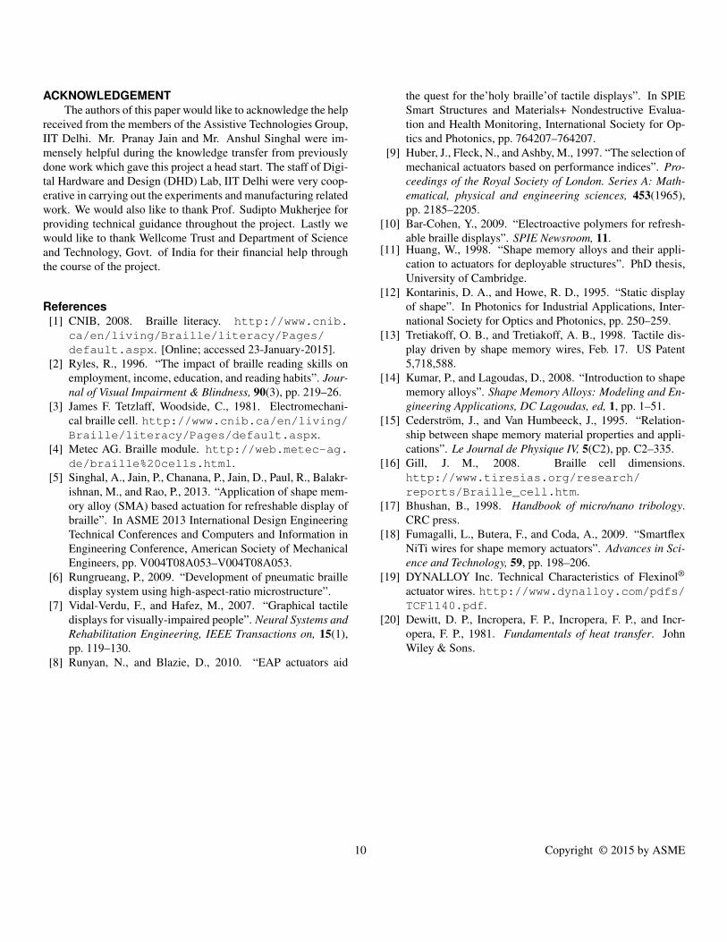
teristic, at different voltages applied across the SMA wire. DCvoltage was applied across the SMA wire via an external powersupply. The actuation process of the Braille dot was recordedusing a 25 fps video camera. The recorded videos were digitallyanalysed (Fig. (14)) to measure: (1) the peak Braille dot strokeat different voltages and (2) the Braille dot stroke with time atdifferent voltages. The observed values have been shown in Fig-ures (15, 16) respectively. Device specifications, as observed,are tabulated in Tab. (6, 7).
DISCUSSIONThis paper has proposed SMA as a suitable alternative to
make affordable RBDs with a cantilever mechanism to reducecontraction in the SMA wire. Optimum driving parametersfor the actuator were calculated and problems related to higherpower consumption, refresh rate, heat accumulation and fatiguelife were addressed.
The actuation mechanism was initially designed to raise theBraille dot by 0.7 mm. However, from the tolerance analysis, itwas observed that the initial Braille dot position should be 0.17mm below the surface of the cap. Therefore, the mechanism wasmodified to give a stroke of 0.9 mm. To obtain this Braille dotstroke, the supplied voltage to the SMA wire should be greaterthan 0.7 V (Fig. (15)). It was also observed that at voltagesgreater than 0.9 V the Braille dot stroke saturates, implying com-plete transformation of SMA from martensite to austenite phase.Another observation was that for Braille dot stroke greater than0.9 mm and actuation time of less than 200 ms, the supplied volt-age should be at least 1.3 V (Fig. (16)). Experimentally observedpower consumption values were found to closely match with thetheoretically calculated values (Tab. (6)).
Cooling system is an essential part of an SMA actuator. Thecooling designs discussed in this paper address the problem oflow refresh rate. A limitation of the thermoelectric cooling sys-tem is its low efficiency as the Peltier cooler itself draws largeamount of power. Forced convective methods require installinga fan throwing air at about 75 cm/sec for cooling the SMA wire
Figure 13. EXPERIMENTAL SETUP TO OBSERVE THE ACTUATIONTIME OF THE ACTUATOR
Figure 14. FRAME BY FRAME DIGITAL ANALYSIS OF BRAILLE DOTACTUATION.
within 200 ms. However, during experimental testing of this de-sign it was observed that the Braille cells which are closer to thefan cool down more effectively than the ones which are fartherdown the array. This is because of the incremental rise in airtemperature as it travels along the Braille cell array. Therefore,alternate passive cooling system designs are being explored.
8 Copyright © 2015 by ASME
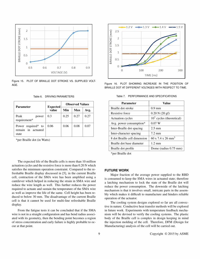
Figure 15. PLOT OF BRAILLE DOT STROKE VS. SUPPLIED VOLT-AGE.
Table 6. DRIVING PARAMETERS
Parameter ExpectedObserved Values
value Min Max Avg.
Peak powerrequirement*
0.3 0.25 0.27 0.27
Power required* toremain in actuatedstate
0.06 0.06 0.08 0.07
*per Braille dot (in Watts)
The expected life of the Braille cells is more than 10 millionactuation cycles and the resistive force is more than 0.20 N whichsatisfies the minimum operation constraint. Compared to the re-freshable Braille display discussed in [5], in the current Braillecell, contraction of the SMA wire has been amplified using acantilever which helped in reducing the strain in SMA wire andreduce the wire length as well. This further reduces the powerrequired to actuate and sustain the temperature of the SMA wireas well as improve the life of the same. Cell height has been re-duced to below 30 mm. The disadvantage of the current Braillecell is that it cannot be used for multi-line refreshable Brailledisplay.
From the fatigue tests it can be concluded that if the SMAwire is not in a straight configuration and has bend radius associ-ated with its geometry, then the bending point becomes a regionof stress concentration and early failure is highly probable to oc-cur at that point.
Figure 16. PLOT SHOWING INCREASE IN THE POSITION OFBRAILLE DOT AT DIFFERENT VOLTAGES WITH RESPECT TO TIME.
Table 7. PERFORMANCE AND SPECIFICATIONS
Parameter ValueBraille dot stroke 0.9 mm
Resistive force 0.20 N (20 gf)
Actuation cycles 107 cycles (theoretical)
Avg. power consumption* 0.07 W
Inter-Braille dot spacing 2.5 mm
Inter-character spacing 7.2 mm
8 dot Braille cell dimension 60 x 7.4 x 26 mm3
Braille dot base diameter 1.2 mm
Braille dot profile Dome (radius 0.75 mm)
*per Braille dot
FUTURE WORKMajor fraction of the average power supplied to the RBD
is consumed to keep the SMA wires in actuated state; thereforea latching mechanism to lock the state of the Braille dot willreduce the power consumption. The downside of the latchingmechanism is that it involves small, intricate parts in the assem-bly which makes it difficult to manufacture and hinders reliableoperation of the actuator.
The cooling system designs explored so far are all convec-tive in nature. Conductive heat transfer methods will be exploredin future work. Experiments with temperature feedback mecha-nism will be devised to verify the cooling systems. The plasticbody of the Braille cell is complex in design keeping in mindthe injection molding of the cell. Therefore, DFM (Design forManufacturing) analysis of the cell will be carried out.
9 Copyright © 2015 by ASME
ACKNOWLEDGEMENTThe authors of this paper would like to acknowledge the help
received from the members of the Assistive Technologies Group,IIT Delhi. Mr. Pranay Jain and Mr. Anshul Singhal were im-mensely helpful during the knowledge transfer from previouslydone work which gave this project a head start. The staff of Digi-tal Hardware and Design (DHD) Lab, IIT Delhi were very coop-erative in carrying out the experiments and manufacturing relatedwork. We would also like to thank Prof. Sudipto Mukherjee forproviding technical guidance throughout the project. Lastly wewould like to thank Wellcome Trust and Department of Scienceand Technology, Govt. of India for their financial help throughthe course of the project.
References[1] CNIB, 2008. Braille literacy. http://www.cnib.
ca/en/living/Braille/literacy/Pages/default.aspx. [Online; accessed 23-January-2015].
[2] Ryles, R., 1996. “The impact of braille reading skills onemployment, income, education, and reading habits”. Jour-nal of Visual Impairment & Blindness, 90(3), pp. 219–26.
[3] James F. Tetzlaff, Woodside, C., 1981. Electromechani-cal braille cell. http://www.cnib.ca/en/living/Braille/literacy/Pages/default.aspx.
[4] Metec AG. Braille module. http://web.metec-ag.de/braille%20cells.html.
[5] Singhal, A., Jain, P., Chanana, P., Jain, D., Paul, R., Balakr-ishnan, M., and Rao, P., 2013. “Application of shape mem-ory alloy (SMA) based actuation for refreshable display ofbraille”. In ASME 2013 International Design EngineeringTechnical Conferences and Computers and Information inEngineering Conference, American Society of MechanicalEngineers, pp. V004T08A053–V004T08A053.
[6] Rungrueang, P., 2009. “Development of pneumatic brailledisplay system using high-aspect-ratio microstructure”.
[7] Vidal-Verdu, F., and Hafez, M., 2007. “Graphical tactiledisplays for visually-impaired people”. Neural Systems andRehabilitation Engineering, IEEE Transactions on, 15(1),pp. 119–130.
[8] Runyan, N., and Blazie, D., 2010. “EAP actuators aid
the quest for the’holy braille’of tactile displays”. In SPIESmart Structures and Materials+ Nondestructive Evalua-tion and Health Monitoring, International Society for Op-tics and Photonics, pp. 764207–764207.
[9] Huber, J., Fleck, N., and Ashby, M., 1997. “The selection ofmechanical actuators based on performance indices”. Pro-ceedings of the Royal Society of London. Series A: Math-ematical, physical and engineering sciences, 453(1965),pp. 2185–2205.
[10] Bar-Cohen, Y., 2009. “Electroactive polymers for refresh-able braille displays”. SPIE Newsroom, 11.
[11] Huang, W., 1998. “Shape memory alloys and their appli-cation to actuators for deployable structures”. PhD thesis,University of Cambridge.
[12] Kontarinis, D. A., and Howe, R. D., 1995. “Static displayof shape”. In Photonics for Industrial Applications, Inter-national Society for Optics and Photonics, pp. 250–259.
[13] Tretiakoff, O. B., and Tretiakoff, A. B., 1998. Tactile dis-play driven by shape memory wires, Feb. 17. US Patent5,718,588.
[14] Kumar, P., and Lagoudas, D., 2008. “Introduction to shapememory alloys”. Shape Memory Alloys: Modeling and En-gineering Applications, DC Lagoudas, ed, 1, pp. 1–51.
[15] Cederstrom, J., and Van Humbeeck, J., 1995. “Relation-ship between shape memory material properties and appli-cations”. Le Journal de Physique IV, 5(C2), pp. C2–335.
[16] Gill, J. M., 2008. Braille cell dimensions.http://www.tiresias.org/research/reports/Braille_cell.htm.
[17] Bhushan, B., 1998. Handbook of micro/nano tribology.CRC press.
[18] Fumagalli, L., Butera, F., and Coda, A., 2009. “SmartflexNiTi wires for shape memory actuators”. Advances in Sci-ence and Technology, 59, pp. 198–206.
[19] DYNALLOY Inc. Technical Characteristics of Flexinol®
actuator wires. http://www.dynalloy.com/pdfs/TCF1140.pdf.
[20] Dewitt, D. P., Incropera, F. P., Incropera, F. P., and Incr-opera, F. P., 1981. Fundamentals of heat transfer. JohnWiley & Sons.
10 Copyright © 2015 by ASME