A Complete Femtocell Network Modeling and …bwn.ece.gatech.edu/papers/2012/c13.pdfA Complete...
6
A Complete Femtocell Network Modeling and Development Platform Elias Chavarria Reyes, David M. Gutierrez-Estevez and Ian F. Akyildiz Broadband Wireless Network Lab School of Electrical and Computer Engineering, Georgia Institute of Technology, Atlanta, GA 30332, USA Email: {elias.chavarria, david.gutierrez, ian}@ece.gatech.edu Abstract—Femtocells have emerged as an alternative solution for operators to improve coverage and throughput in indoor envi- ronments. However, modeling and development platforms are still needed in order to test implementation-specific characteristics of femtocells, such as interference mitigation techniques and self- organizing algorithms. Using OPNET, a high fidelity simulation environment for wireless networks, a femtocell modeling and development platform is created, closely following the specifi- cations dictated by 3GPP regarding the entities, functionalities, procedures, and message formats for femtocell networks. It is shown how the platform reflects the effect of both interference and backhaul degradation on the overall performance of the net- work, which represent the key concerns for operators nowadays regarding femtocell deployments. I. I NTRODUCTION Femtocells have emerged in the last few years as a solution for operators to increase capacity and coverage in indoor environments. As such, they have been introduced in most current cellular communication standards: UMTS/HSPA, LTE, CDMA2000, WiMAX. Among these, UMTS/HSPA networks are currently the most widely deployed. Together, they account for more than 70 percent of commercial 3G networks [1]. 3GPP, in charge of developing UMTS/HSPA, first introduced femtocells in its Release 8 [2] and has continued adding enhancements in subsequent releases. Throughout the speci- fications, 3GPP has left several aspects of their functioning as implementation specific. This leaves room for continuous research and development to improve the performance of fem- tocells, and differentiate the femtocell offerings from different manufacturers and operators. Due to the relevance that UMTS/HSPA currently have and will continue having, even with the introduction of newer standards (e.g. LTE-Advanced), it is of great importance to count with tools where femtocell-related development can be perfomed and evaluated. These tools should address not only the link-level characteristics but also the system level behavior associated with UMTS/HSPA networks. Based on OPNET Modeler Wireless Suite and 3GPP’s standards, we have developed the simulation models and implementation of the main elements of a femtocell enhanced UMTS net- work: the Home Node-B (HNB) and Home Node-B Gateway (HNB-GW), as well as their related procedures and standard messages according to 3GPP’s ASN.1 definitions. OPNET provides a platform for high fidelity modeling, simulation and analysis of a broad range of wireless networks, allowing the design and optimization of proprietary wireless protocols [3]. To the best of our knowledge, there aren’t any publicly avail- able simulation tools that address the needs satisfied by our OPNET-based femtocell modeling and development platform. The rest of the paper is organized as follows. Section II describes the basic architecture of a UMTS Cellular Network enhanced to support femtocells. In Section III, we describe the design and implementation of these elements in OPNET. Sim- ulation results are then provided in Section IV. Conclusions and future work are provided in Section V and Section VI. II. ARCHITECTURE In addition to the typical elements found in the packet switched (PS) section of a UMTS Network, namely Node- B, Radio Network Controller (RNC), Serving GPRS Support Node (SGSN), and Gateway GPRS Support Node (GGSN), two new main entities must be added in order to support femtocells: the HNB and the HNB-GW, as depicted in Fig. 1. The HNB-GW appears as a typical RNC towards the UMTS core network (CN) (i.e. SGSN and GGSN for the PS section). Therefore, to communicate with the CN, it utilizes the same Iu interface [4] as the one used by RNCs for this purpose (Iu-PS towards the PS section, and Iu-CS towards the circuit switched section). Its main role is to act as an aggregator for all the HNB connections. On the other hand, the HNB appears as any other Node-B to the user equipments (UEs), providing the same Uu air interface as Node-Bs do. Between the HNB-GW and the HNB a new interface is defined, the Iuh interface [2], to support HNB-specific procedures and a lightweight mechanism for carrying data and control traffic between the HNB-GW and the HNBs. In addition to the HNB and HNB-GW, additional support elements are also introduced in the network: the Security Gateway and HNB Management System. They provide a secure connection between HNB and HNB-GW, and provide configuration information to HNBs, respectively. The new Iuh interface can be seen as a simplified version of the Iu interface, as shown in Fig. 2. It removes heavy- weight protocols from the Iu interface and introduces two new protocols: Radio Access Network Application Part -RANAP- User Adaptation (RUA) Signaling [5], and Home Node B Application Part (HNBAP) [6]. RUA’s main objective is to transparently transfer RANAP messages between the CN and the HNB, using the HNB-GW as intermediate entity. On the 978-1-4673-0921-9/12/$31.00 ©2012 IEEE Globecom 2012 - Wireless Networking Symposium 5142
Transcript of A Complete Femtocell Network Modeling and …bwn.ece.gatech.edu/papers/2012/c13.pdfA Complete...

A Complete Femtocell Network Modeling andDevelopment Platform
Elias Chavarria Reyes, David M. Gutierrez-Estevez and Ian F. AkyildizBroadband Wireless Network Lab
School of Electrical and Computer Engineering, Georgia Institute of Technology, Atlanta, GA 30332, USAEmail: {elias.chavarria, david.gutierrez, ian}@ece.gatech.edu
Abstract—Femtocells have emerged as an alternative solutionfor operators to improve coverage and throughput in indoor envi-ronments. However, modeling and development platforms are stillneeded in order to test implementation-specific characteristics offemtocells, such as interference mitigation techniques and self-organizing algorithms. Using OPNET, a high fidelity simulationenvironment for wireless networks, a femtocell modeling anddevelopment platform is created, closely following the specifi-cations dictated by 3GPP regarding the entities, functionalities,procedures, and message formats for femtocell networks. It isshown how the platform reflects the effect of both interferenceand backhaul degradation on the overall performance of the net-work, which represent the key concerns for operators nowadaysregarding femtocell deployments.
I. INTRODUCTION
Femtocells have emerged in the last few years as a solutionfor operators to increase capacity and coverage in indoorenvironments. As such, they have been introduced in mostcurrent cellular communication standards: UMTS/HSPA, LTE,CDMA2000, WiMAX. Among these, UMTS/HSPA networksare currently the most widely deployed. Together, they accountfor more than 70 percent of commercial 3G networks [1].3GPP, in charge of developing UMTS/HSPA, first introducedfemtocells in its Release 8 [2] and has continued addingenhancements in subsequent releases. Throughout the speci-fications, 3GPP has left several aspects of their functioningas implementation specific. This leaves room for continuousresearch and development to improve the performance of fem-tocells, and differentiate the femtocell offerings from differentmanufacturers and operators.
Due to the relevance that UMTS/HSPA currently have andwill continue having, even with the introduction of newerstandards (e.g. LTE-Advanced), it is of great importance tocount with tools where femtocell-related development canbe perfomed and evaluated. These tools should address notonly the link-level characteristics but also the system levelbehavior associated with UMTS/HSPA networks. Based onOPNET Modeler Wireless Suite and 3GPP’s standards, wehave developed the simulation models and implementationof the main elements of a femtocell enhanced UMTS net-work: the Home Node-B (HNB) and Home Node-B Gateway(HNB-GW), as well as their related procedures and standardmessages according to 3GPP’s ASN.1 definitions. OPNETprovides a platform for high fidelity modeling, simulation andanalysis of a broad range of wireless networks, allowing the
design and optimization of proprietary wireless protocols [3].To the best of our knowledge, there aren’t any publicly avail-able simulation tools that address the needs satisfied by ourOPNET-based femtocell modeling and development platform.
The rest of the paper is organized as follows. Section IIdescribes the basic architecture of a UMTS Cellular Networkenhanced to support femtocells. In Section III, we describe thedesign and implementation of these elements in OPNET. Sim-ulation results are then provided in Section IV. Conclusionsand future work are provided in Section V and Section VI.
II. ARCHITECTURE
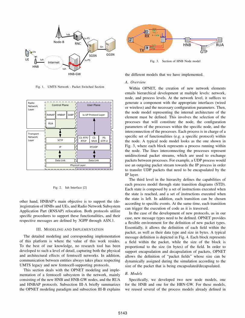
In addition to the typical elements found in the packetswitched (PS) section of a UMTS Network, namely Node-B, Radio Network Controller (RNC), Serving GPRS SupportNode (SGSN), and Gateway GPRS Support Node (GGSN),two new main entities must be added in order to supportfemtocells: the HNB and the HNB-GW, as depicted in Fig. 1.The HNB-GW appears as a typical RNC towards the UMTScore network (CN) (i.e. SGSN and GGSN for the PS section).Therefore, to communicate with the CN, it utilizes the sameIu interface [4] as the one used by RNCs for this purpose(Iu-PS towards the PS section, and Iu-CS towards the circuitswitched section). Its main role is to act as an aggregatorfor all the HNB connections. On the other hand, the HNBappears as any other Node-B to the user equipments (UEs),providing the same Uu air interface as Node-Bs do. Betweenthe HNB-GW and the HNB a new interface is defined, theIuh interface [2], to support HNB-specific procedures and alightweight mechanism for carrying data and control trafficbetween the HNB-GW and the HNBs. In addition to the HNBand HNB-GW, additional support elements are also introducedin the network: the Security Gateway and HNB ManagementSystem. They provide a secure connection between HNB andHNB-GW, and provide configuration information to HNBs,respectively.
The new Iuh interface can be seen as a simplified versionof the Iu interface, as shown in Fig. 2. It removes heavy-weight protocols from the Iu interface and introduces two newprotocols: Radio Access Network Application Part -RANAP-User Adaptation (RUA) Signaling [5], and Home Node BApplication Part (HNBAP) [6]. RUA’s main objective is totransparently transfer RANAP messages between the CN andthe HNB, using the HNB-GW as intermediate entity. On the
978-1-4673-0921-9/12/$31.00 ©2012 IEEE
Globecom 2012 - Wireless Networking Symposium
5142
UE
HNBInternet
HNB-GW
SGSN GGSN
Node-B RNC
Iub
Iu-PS
Iu-PS
Iuh
Iuh
Gn
Uu
Fig. 1. UMTS Network - Packet Switched Section
TransportNetworkLayer
RadioNetworkLayer
User PlaneControl Plane
Physical Layer
Data Link Data Link
IP
SCTP
IP/UDP
CS: RTP/RTCP
CS: MUX
PS: GTP-U
RANAP HNBAP SABP
RUA
Iu UP Protocol Layer
Fig. 2. Iuh Interface [2]
other hand, HNBAP’s main objective is to support the (de-)registration of HNBs and UEs, and Radio Network SubsystemApplication Part (RNSAP) relocation. Both protocols utilizespecific procedures to support these functionalities, and theirrespective messages are defined by 3GPP through ASN.1.
III. MODELING AND IMPLEMENTATION
The detailed modeling and corresponding implementationof this platform is where the value of this work resides.To the best of our knowledge, no research tool has beendeveloped to such a level of detail, capturing both the physicaland architectural effects of femtocell networks. In addition,communication between entities always takes place respectingUMTS legacy and new femtocell-supporting protocols.
This section deals with the OPNET modeling and imple-mentation of a femtocell subsystem in the network, mainlyconsisting of the new HNB and HNB-GW nodes, and the RUAand HNBAP protocols. Subsection III-A briefly summarizesthe OPNET modeling paradigm and subsection III-B explains
HNB
GTP
RUA
RX
TX
Fig. 3. Section of HNB Node model
the different models that we have implemented.
A. Overview
Within OPNET, the creation of new network elementsentails hierarchical development at multiple levels: network,node, and process levels. At the network level, it suffices togenerate a component with the appropriate interfaces (wiredor wireless) and the necessary configuration parameters. Then,the node model representing the internal architecture of theelement must be defined. This involves the selection of theprocesses that will constitute the node, the configurationparameters of the processes within the specific node, and theinterconnection of the processes. Each process is in charge of aspecific set of functionalities (e.g. a specific protocol) withinthe node. A typical node model looks as the one shown inFig. 3, where each block represents a process running withinthe node. The lines interconnecting the processes representunidirectional packet streams, which are used to exchangepackets between processes. For example, a UDP process woulduse an outgoing packet stream towards the IP process in orderto transfer UDP packets that need to be encapsulated by theIP layer.
The third level in the hierarchy defines the capabilities ofeach process model through state transition diagrams (STD).Each state is composed by a set of instructions executed whenthe state is reached, and a set of instructions executed whenthe state is left. In addition, each transition can be chosenaccording to specific events. At the same time, each transitioncan trigger the execution of code as it is traversed.
In the case of the development of new protocols, as in ourcase, new message types need to be defined. OPNET providesa flexible environment for the definition of new packet types.Essentially, it allows the definition of each field within thepacket, as well as their data type and size in bytes. A typicalmessage definition is depicted in Fig. 4. Each block representsa field within the packet, while the size of the block isproportional to the size (in bytes) of the field. In order tosupport encapsulation and decapsulation of packets, OPNETallows the definition of “packet fields” whose size can bedynamically assigned during the simulation according to thesize of the packet that is being encapsulated/decapsulated.
B. Models
Specifically, we developed two new node models, onefor the HNB and one for the HBN-GW. For these models,we reused several of the process models already defined in
5143

OPNET (e.g. IP, UDP, TCP), and we updated others (e.g. gtp,sgsn) in order to support the new node models. In addition,we developed new process models: hnb, rua, and hnb-gwprocess models. These are in charge of the core functionalitiesperformed by the HNB and HNB-GW nodes. Furthermore,we created new packet formats for the RUA and HNBAPprotocols, as per the ASN.1 definitions provided by 3GPP inorder to maintain compliance with the standard.
1) HNB: In UMTS, the HNB is responsible for the func-tionalities provided by the Node-B and most of the functionscorresponding to the RNC. An exception is the managementfunctionality for supporting multiple Node-B’s at the RNC,analog to the management of multiple HNBs at the HNB-GW,which does not reside in the HNB node. Yet radio resourcemanagement and some mobility management functions doneed to be implemented at the HNB. Taking these issuesinto account, we utilized as baseline the existing models inOPNET for the Node-B and RNC node and process modelsin order to develop the node and process models of theHNB, as shown in Fig. 3. The HNB contains the radiotransmitter and radio receiver, as the Node-B, while at thesame time utilizes the GTP protocol for the transmission of Iu-PS related data, as the RNC. We updated the gtp process modelin order to seamlessly integrate with our new hnb processmodel for the transmission and reception of control and userdata. Two additional processes were integrated: a multiplexermodule enabling future sectorized femtocells, and the modulein charge of executing the RUA protocol.
Within OPNET, the code related to the physical layerprocessing in the transmitting and receiving ends, is groupedin “pipeline stages”. In addition to modifying the existingpipeline stages of the Node-B and UE, we also createddedicated code to deal with the pipeline stages of the radiotransmitter and radio receiver of the HNB. By doing so, weprovide a platform that facilitates the development, implemen-tation and testing of interference mitigation techniques thataffect only the HNBs within the network.
The developed HNB models can be configured in each ofthe three access modes defined by 3GPP:
• Open mode: Any user can connect to the femtocell.• Closed mode: Only a specific set of users, the ones
belonging to the Closed Subscriber Group (CSG) areallowed to connect to the femtocell.
• Hybrid mode: Any user can connect. However, usersbelonging to the CSG will receive prioritized service.
2) HNB-GW: Since the HNB-GW requires a small subsetof the functionalities of an RNC, the core functionality of theHNB-GW we developed goes into supporting the terminationof both RUA and HNBAP protocols, and the managementcapability for supporting multiple femtocells. Similarly to theHNB, we updated the gtp process model in order to seamlesslywork with our new hnb-gw process model for the transmissionof control and user data in both, the Iu-PS and the Iuhinterface. Due to OPNET’s current approach of initializingthe relation between SGSNs and RNCs, we also updated thesgsn process model in order to initialize a relation not only
Preamble(8 bits)
Proc. Code(8 bits)
Criticality(2 bits)
Padding(6 bits)
Preamble1(2 bits)
Length(14 bits)
Preamble2(8 bits)
SEQ_LENGTH(16 bits)
Id_0(16 bits)
Id_1(16 bits)
Id_2(16 bits)
Criticality(2 bits)
Padding(6 bits)
Criticality(2 bits)
Padding(6 bits)
Criticality(2 bits)
Padding(6 bits)
Length_0(8 bits)
Length_1(8 bits)
Preamble2(2 bits)
CN Domain Indicator(8 bits)
Context ID(24 bits)
Length(14 bits)
RANAP message(inherited size)
Fig. 4. Packet format of RUA Direct Transfer Message
with RNCs but also with HNB-GWs. The HNB-GW modelwe developed can support multiple HNBs configured as anycombination of open, closed, and hybrid femtocells.
3) RUA and HNBAP: A major task for enabling femtocellstandardized networks was the development of both the RUAand HNBAP protocols, specifically defined by 3GPP for theIuh interface. While the HNBAP protocol was integrated intothe higher layer process models (hnb and hnb-gw), the RUAprotocol was developed as an independent process. Therefore,the gtp process model was also updated to support dataexchange with the RUA process model.
Within the RUA process model, we implemented the DirectTransfer and HNB Originated Connect procedures as definedin [5]. These two procedures support the establishment of aninitial connection for the UEs and the subsequent exchange ofRANAP control signaling between the HNB and HNB-GW.The corresponding message format for these procedures weregenerated from their 3GPP ASN.1 definition. As an exampleof the message formats that were developed, Fig. 4 depicts themessage format for the RUA Direct Transfer Message used tocarry RANAP messages between the HNB and HNB-GW.
For the HNBAP protocol, we followed a similar approachto the Node-B Application Protocol (NBAP) implemented inOPNET. The NBAP has as termination entities the RNC andthe Node-B, and takes care of the radio link establishment,modification and removal at the Node-B. In OPNET, the RNChas a common process implementing RANAP and NBAPas separate states of the same process. Following a similarapproach, the HNBAP is implemented between the HNBand HNB-GW termination entities, and its functionality isintegrated as a separate state of the same process as RANAP.
The main functionality of HNBAP is the UE RegistrationProcedure. This procedure enables the registration of a UE atthe CN. Based on the 3GPP ASN.1 definition, we generatedthe message format for the three possible messages associatedwith this procedure: UE Register Request, UE Register Accept,UE Register Reject. In addition, we took into account thenode where access control based on CSG should be performed,according to the type of HNB from which the UE is attachingand the CSG capabilities of the UE [6]. In order to do this, weupdated the UE node model to include a CSG list of allowedCSG IDs.
5144
RNC
SGSNGGSN
Node-B
HNB-GW
Server
HNB
Internet
UE
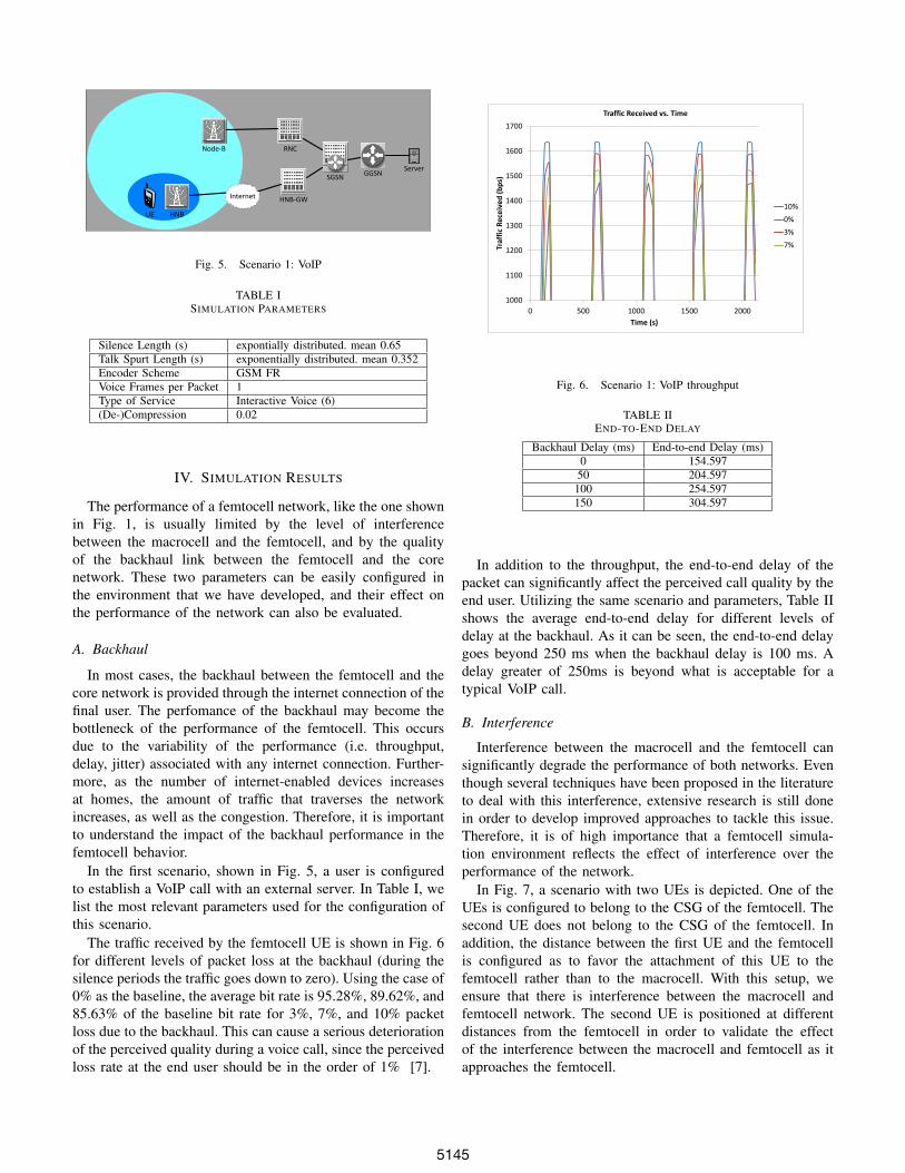
Fig. 5. Scenario 1: VoIP
TABLE ISIMULATION PARAMETERS
Silence Length (s) expontially distributed. mean 0.65Talk Spurt Length (s) exponentially distributed. mean 0.352Encoder Scheme GSM FRVoice Frames per Packet 1Type of Service Interactive Voice (6)(De-)Compression 0.02
IV. SIMULATION RESULTS
The performance of a femtocell network, like the one shownin Fig. 1, is usually limited by the level of interferencebetween the macrocell and the femtocell, and by the qualityof the backhaul link between the femtocell and the corenetwork. These two parameters can be easily configured inthe environment that we have developed, and their effect onthe performance of the network can also be evaluated.
A. Backhaul
In most cases, the backhaul between the femtocell and thecore network is provided through the internet connection of thefinal user. The perfomance of the backhaul may become thebottleneck of the performance of the femtocell. This occursdue to the variability of the performance (i.e. throughput,delay, jitter) associated with any internet connection. Further-more, as the number of internet-enabled devices increasesat homes, the amount of traffic that traverses the networkincreases, as well as the congestion. Therefore, it is importantto understand the impact of the backhaul performance in thefemtocell behavior.
In the first scenario, shown in Fig. 5, a user is configuredto establish a VoIP call with an external server. In Table I, welist the most relevant parameters used for the configuration ofthis scenario.
The traffic received by the femtocell UE is shown in Fig. 6for different levels of packet loss at the backhaul (during thesilence periods the traffic goes down to zero). Using the case of0% as the baseline, the average bit rate is 95.28%, 89.62%, and85.63% of the baseline bit rate for 3%, 7%, and 10% packetloss due to the backhaul. This can cause a serious deteriorationof the perceived quality during a voice call, since the perceivedloss rate at the end user should be in the order of 1% [7].
1000
1100
1200
1300
1400
1500
1600
1700
0 500 1000 1500 2000
Traf
fic
Re
ceiv
ed
(b
ps)
Time (s)
Traffic Received vs. Time
10%
0%
3%
7%
Fig. 6. Scenario 1: VoIP throughput
TABLE IIEND-TO-END DELAY
Backhaul Delay (ms) End-to-end Delay (ms)0 154.59750 204.597
100 254.597150 304.597
In addition to the throughput, the end-to-end delay of thepacket can significantly affect the perceived call quality by theend user. Utilizing the same scenario and parameters, Table IIshows the average end-to-end delay for different levels ofdelay at the backhaul. As it can be seen, the end-to-end delaygoes beyond 250 ms when the backhaul delay is 100 ms. Adelay greater of 250ms is beyond what is acceptable for atypical VoIP call.
B. Interference
Interference between the macrocell and the femtocell cansignificantly degrade the performance of both networks. Eventhough several techniques have been proposed in the literatureto deal with this interference, extensive research is still donein order to develop improved approaches to tackle this issue.Therefore, it is of high importance that a femtocell simula-tion environment reflects the effect of interference over theperformance of the network.
In Fig. 7, a scenario with two UEs is depicted. One of theUEs is configured to belong to the CSG of the femtocell. Thesecond UE does not belong to the CSG of the femtocell. Inaddition, the distance between the first UE and the femtocellis configured as to favor the attachment of this UE to thefemtocell rather than to the macrocell. With this setup, weensure that there is interference between the macrocell andfemtocell network. The second UE is positioned at differentdistances from the femtocell in order to validate the effectof the interference between the macrocell and femtocell as itapproaches the femtocell.
5145

RNC
SGSNGGSN
Node-B
HNB-GW
Server
HNB
Internet
fUE
mUE
Fig. 7. Scenario 2: Interference
0
1000
2000
3000
4000
5000
6000
7000
8000
390 590 790 990
Thro
ugh
pu
t (b
ps)
Time (s)
Throughput vs. Time
60 m
50 m
100m
Fig. 8. Scenario 2: Throughput
The simulation is configured to have two phases. Duringthe first phase, both users transmit simultaneously (one tothe femtocell, and one to the macrocell). During the secondphase, the macrocell user stops transmitting, removing anyinterference to the femtocell user. Fig. 8 shows the simulationresult of the traffic received by the femtocell user for dif-ferent macrouser distances from the femtocell. As the mUEapproaches the femtocell network, the achievable throughputby the femtocell user during the first phase of the simulationdecreases. Once the second phase of the simulation starts,the femtocell user is able to achieve its highest possiblethroughput. This behavior demonstrates that the developedsimulation environment reflects the effect of interference overthe performance of the network.
In addition to the behavior seen in the previous scenarios,we analyzed additional interactions between femtocell andmacrocell. In Fig. 9, Fig. 10 and Fig. 11, three of theseinteractions are depicted. In all cases, a user (UE 1 fromnow on) belonging to the CSG of the femtocell starts atransmission. Afterwards, a second user (UE 2 from nowon), not belonging to the CSG of the femtocell, starts atransmission and later stops it. Therefore, the interference toUE 1 is removed.
In the first instance of the interaction between both users,
0
2000
4000
6000
8000
10000
12000
0 200 400 600 800 1000
Thro
ugh
pu
t (b
ps)
Time (s)
Throughput vs. Time
UE 1
UE 2
Fig. 9. Femto-macro interactions: First Instance
0
1000
2000
3000
4000
5000
6000
7000
8000
9000
0 200 400 600 800 1000
Thro
ugh
pu
t (b
ps)
Time (s)
Throughput vs. Time
UE 1
UE 2
Fig. 10. Femto-macro interactions: Second Instance
UE 2 is able to achieve its maximum throughput. However,the throughput of UE 1 reduces significantly while UE 1 wastrasnsmitting. Looking into the transmission power utilizedby both users (which is readily available in OPNET), weidentified that the UMTS power control algorithm (which ismodeled in OPNET) increases the transmission power of theusers in order to compensante for the additional interference.In the case of UE 2, there is enough room to increase the powerand compensate for the interference. However, UE 1 reachesits maximum transmission power (27 dB) before being able tocompletelely compensate for the interefence cause by UE 2.
In the second instance of the interaction between both users,both UE 1 and UE 2 achieve a limited throughput. In thiscase, both users reach their maximum transmission powerbefore being able to completely compensate the interferencecaused by each other. Therefore, they are unable to reach theirrequired SINR, leading to the limited throughput.
In the third instance of the interaction between both users,
5146

0
1000
2000
3000
4000
5000
6000
7000
8000
9000
0 200 400 600 800 1000
Thro
ugh
pu
t (b
ps)
Time (s)
Throughput vs. Time
UE 1
UE 2
Fig. 11. Femto-macro interactions: Third Instance
UE 2 again achieves a limited throughput. However, UE1 achieves zero throughput while UE 2 was transmitting.Compared to the previous cases, even though UE 1 reachesits maximum transmission power (27 dB), the received SINRis far below the required SINR to be able to achieve anythroughput at all.
As seen from these three cases, the mutual degradation ofthe quality experienced by the femtocell and macrocell cangreatly vary in a case by cases basis, even within a singlescenario, which is clearly captured in our simulation platform.
V. FUTURE WORK
Since the current version of OPNET does not support inter-RNC mobility, and a HNB-GW appears as an RNC to the CN,we have left as further work the implementation of mobility-related procedures between HNB-GW and RNCs. The Iurhinterface between HNBs, recently introduced by 3GPP, willalso be implemented in a future version of our models.We have already started extending this work to OPNET’sLTE Simulation framework due to LTE’s growing importanceas a cellular wireless standard. We will not only evaluateexisting interference mitigation techniques, but also developand evaluate new ones with the models created.
VI. CONCLUSION
Femtocells have emerged as the most recent alternativefor operators to improve indoor coverage and throughput.However, given that several aspects are left as implementationspecific, there exists a need for development and testingtools for femtocells. To fill this need, we created a femtocellmodeling and development platform based on OPNET, ahigh-fidelity simulation environment. This platform closelyfollows 3GPP specifications regarding femtocells in termsof entities, functionalities, procedures, and message formats.We have shown that the platform effectively reflects the keyconcerns of operators when implementing and developingsolutions for femtocells; namely interference and backhaul
issues. The platform that we created serves as the basis for thefuture development and implementation of femtocell-specificalgorithms such as interference mitigation and self-organizingalgorithms.
ACKNOWLEDGMENT
This work was supported by SENACYT and Fundacion CajaMadrid.
REFERENCES
[1] 3GPP - W-CDMA. 3GPP. [Online]. Available:http://www.3gpp.org/article/w-cdma
[2] 3GPP, “TS 25.467 UTRAN architecture for 3G Home NodeB (HNB),” Tech. Rep., December 2011. [Online]. Available:http://www.3gpp.org/ftp/Specs/html-info/25467.htm
[3] Wireless network simulation: Opnet modelerwireless suite. OPNET. [Online]. Available:http://www.opnet.com/solutions/network rd/modeler wireless.html
[4] 3GPP, “TS 25.410 UTRAN Iu Interface: general aspectsand principles,” Tech. Rep., June 2011. [Online]. Available:http://www.3gpp.org/ftp/Specs/html-info/25410.htm
[5] ——, “TS 25.468 UTRAN Iuh Interface RANAP User Adaption (RUA)signalling,” Tech. Rep., September 2011.
[6] ——, “TS 25.469 UTRAN Iuh interface Home Node B (HNB) Applica-tion Part (HNBAP) signalling,” Tech. Rep., June 2011.
[7] T. Szigeti and C. Hattingh. (2004, December) Qualityof service design overview. Cisco. [Online]. Available:http://www.ciscopress.com/articles/article.asp?p=357102
5147