A complete Department of the Army Permit Application ... · 23/09/2010 · Ahi Aquaculture Project...
24
Transcript of A complete Department of the Army Permit Application ... · 23/09/2010 · Ahi Aquaculture Project...


Ahi Aquaculture Project
20º05'40.00" N 155º55'40.00" W
Monty Richards (Kahua Ranch)Pono von Holt (Ponoholo Ranch) 5-8-001 and 5-9-003 (3rd Division)
HAWAI'I ISLANDUS HI
State Marine WatersPOH-2009-00263
9/4/2010
2.6 nautical miles due southwest of Malae Point, N. Kohala, HI
Tuna Cultivation
LOCATION MAP
5

Ahi Aquaculture Project
20º05'40.00" N 155º55'40.00" W
Monty Richards (Kahua Ranch)Pono von Holt (Ponoholo Ranch) 5-8-001 and 5-9-003 (3rd Division)
HAWAI'I ISLANDUS HI
State Marine WatersPOH-2009-00263
9/4/2010
2.6 nautical miles due southwest of Malae Point, N. Kohala, HI
Tuna Cultivation
SANDY BOTTOM
1320 feet/ 402 meters depth of Sea Floor
1254 feet/ 382 meters to Sea Floor
Submersible Pens (51 m diameter)
50 m
20 m Pen Depth
Dynamic Positioning/ Auto Feed Buoy
Towing Pendulumand Weighted Triangle
Weighted Lower Frame
2 5
DEPLOYED INITIAL DEMONSTRATION SYSTEMCROSS SECTIONAL VIEW
Z drive with 360o Rotation of Thrust

Ahi Aquaculture Project
20º05'40.00" N 155º55'40.00" W
Monty Richards (Kahua Ranch)Pono von Holt (Ponoholo Ranch) 5-8-001 and 5-9-003 (3rd Division)
HAWAI'I ISLANDUS HI
State Marine WatersPOH-2009-00263
9/4/2010
2.6 nautical miles due southwest of Malae Point, N. Kohala, HI
Tuna Cultivation
3
DYNAMIC POSITIONING/ AUTOFEED BUOY
5
CROSS SECTIONAL VIEW

Ahi Aquaculture Project
20º05'40.00" N 155º55'40.00" W
Monty Richards (Kahua Ranch)Pono von Holt (Ponoholo Ranch) 5-8-001 and 5-9-003 (3rd Division)
HAWAI'I ISLANDUS HI
State Marine WatersPOH-2009-00263
9/4/2010
2.6 nautical miles due southwest of Malae Point, N. Kohala, HI
Tuna Cultivation
4
DYNAMIC POSITIONING/ AUTOFEED BUOY
5
TOP SIDE VIEW
456.000 in ( 38' 0")
DO
WN
456.000 in (38' 0")
160.125 in366.375 in

Ahi Aquaculture Project
20º05'40.00" N 155º55'40.00" W
Monty Richards (Kahua Ranch)Pono von Holt (Ponoholo Ranch) 5-8-001 and 5-9-003 (3rd Division)
HAWAI'I ISLANDUS HI
State Marine WatersPOH-2009-00263
9/4/2010
2.6 nautical miles due southwest of Malae Point, N. Kohala, HI
Tuna Cultivation
SANDY BOTTOM
1320 feet/ 402 meters depth of Sea Floor
1078 feet/ 327 meters to Sea Floor from bottom of Oceansphere
5
(4) SHIELED LOW RPM THRUSTERS
COLLAPSIBLE BLADDER Oceansphere 55 m diameter
DEPLOYED OCEANSPHERE
Dynamic Positioning/ Auto Feed Buoy
5
CROSS SECTIONAL VIEW

D. STRUCTURES IN NAVIGABLE WATERS
1. What specific structures will be constructed (type and size)?
The project will move in phases and structures will be deployed at the Ocean Lease Site, as described here. The timeline for the project will be the completion of a Command and Control Module and testing in 2010, deployment of a 1:20 scale Oceansphere prototype equipped with the command and control module implemented in early 2011, AEG demonstration system to be deployed by end of 2011, and, deployment of the first Oceansphere by the end of 2012. (1) Prototype Oceansphere ������������ ���������������������� ������������ ����������������������diameter will be deployed at the ocean site to measure currents and forces on the sphere. This is a 1:20 radius scale model of the full sized Oceansphere. The sphere will be constructed as a geodesic sphere from PVC tubing and covered with candidate netting materials. The sphere will be deployed for two separate three month deployment periods. Currents and resulting forces acting on the sphere will be measured with an Acoustic Doppler Current Profiler (ADCP) and a Marine Load Cell Dynamometer. To separate the forces on the sphere vs. deployment line and float buoy, we are including a �control� experiment where we only deploy the floats, ADCP and force meter without the sphere. Then we will conduct ���������experiment where we add the sphere and repeat the measurements over a three month deployment period. In this way we can calculate the force on the sphere by Equation 1: F(sphere) = F(sphere + control) - F(control) eq. 1 The control experiment will be conducted the first three months and the second ����������������������� ��� �����three months. These time series experiments will generate a total of six months of ADCP (current) data. In simple terms, we will be measuring currents and drag at the same time and subtracting out the force of the control experiment. That way we measure forces on the sphere as a function of current speed and direction. That function which is really an equation is compared to the model equation and the model is then improved with real world validation.
1
J3EC9ASK
Typewritten Text
Project Description
J3EC9ASK
Typewritten Text
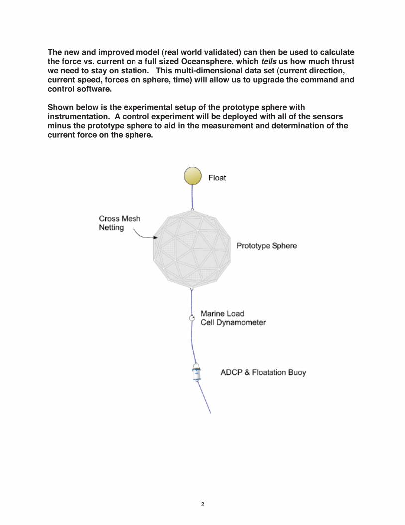
The new and improved model (real world validated) can then be used to calculate the force vs. current on a full sized Oceansphere, which tells us how much thrust we need to stay on station. This multi-dimensional data set (current direction, current speed, forces on sphere, time) will allow us to upgrade the command and control software. Shown below is the experimental setup of the prototype sphere with instrumentation. A control experiment will be deployed with all of the sensors minus the prototype sphere to aid in the measurement and determination of the current force on the sphere.
2
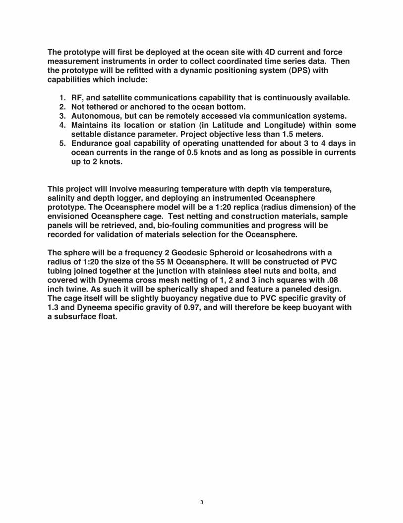
The prototype will first be deployed at the ocean site with 4D current and force measurement instruments in order to collect coordinated time series data. Then the prototype will be refitted with a dynamic positioning system (DPS) with capabilities which include:
1. RF, and satellite communications capability that is continuously available. 2. Not tethered or anchored to the ocean bottom. 3. Autonomous, but can be remotely accessed via communication systems. 4. Maintains its location or station (in Latitude and Longitude) within some
settable distance parameter. Project objective less than 1.5 meters. 5. Endurance goal capability of operating unattended for about 3 to 4 days in
ocean currents in the range of 0.5 knots and as long as possible in currents up to 2 knots.
This project will involve measuring temperature with depth via temperature, salinity and depth logger, and deploying an instrumented Oceansphere prototype. The Oceansphere model will be a 1:20 replica (radius dimension) of the envisioned Oceansphere cage. Test netting and construction materials, sample panels will be retrieved, and, bio-fouling communities and progress will be recorded for validation of materials selection for the Oceansphere. The sphere will be a frequency 2 Geodesic Spheroid or Icosahedrons with a radius of 1:20 the size of the 55 M Oceansphere. It will be constructed of PVC tubing joined together at the junction with stainless steel nuts and bolts, and covered with Dyneema cross mesh netting of 1, 2 and 3 inch squares with .08 inch twine. As such it will be spherically shaped and feature a paneled design. The cage itself will be slightly buoyancy negative due to PVC specific gravity of 1.3 and Dyneema specific gravity of 0.97, and will therefore be keep buoyant with a subsurface float.
3
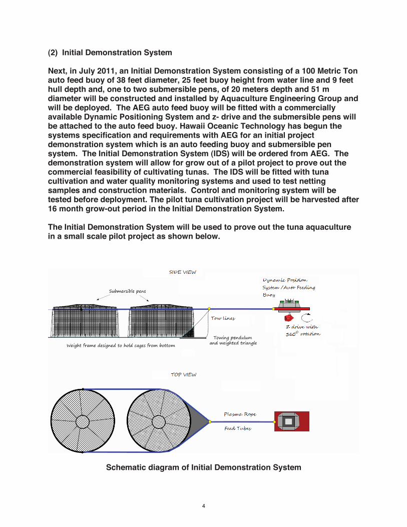
(2) Initial Demonstration System Next, in July 2011, an Initial Demonstration System consisting of a 100 Metric Ton auto feed buoy of 38 feet diameter, 25 feet buoy height from water line and 9 feet hull depth and, one to two submersible pens, of 20 meters depth and 51 m diameter will be constructed and installed by Aquaculture Engineering Group and will be deployed. The AEG auto feed buoy will be fitted with a commercially available Dynamic Positioning System and z- drive and the submersible pens will be attached to the auto feed buoy. Hawaii Oceanic Technology has begun the systems specification and requirements with AEG for an initial project demonstration system which is an auto feeding buoy and submersible pen system. The Initial Demonstration System (IDS) will be ordered from AEG. The demonstration system will allow for grow out of a pilot project to prove out the commercial feasibility of cultivating tunas. The IDS will be fitted with tuna cultivation and water quality monitoring systems and used to test netting samples and construction materials. Control and monitoring system will be tested before deployment. The pilot tuna cultivation project will be harvested after 16 month grow-out period in the Initial Demonstration System. The Initial Demonstration System will be used to prove out the tuna aquaculture in a small scale pilot project as shown below.
Schematic diagram of Initial Demonstration System
4

The Initial Demonstration System will use an already available Dynamic Positioning System fitted to the AEG auto feed buoy. Kongsberg Maritime offers a Dynamic Positioning System (DPS), shown below, which is a computer ������� �� ������������������� ������������������!����������� ��� �"�� �using onboard thrusters. Position reference sensors, combined with wind sensors, motion sensors and gyro compasses, provide information to the computer pertaining to the vessel's position and the magnitude and direction of environmental forces affecting its position.
The computer program contains a mathematical model of the platform that includes information pertaining to the wind and current drag of the vessel and the location of the thrusters. This knowledge, combined with the sensor information, allows the computer to calculate the required steering angle and thruster output for each thruster. This allows operations at sea where mooring or anchoring is not feasible due to deep water.
Kongsberg Maritime commercially available Dynamic Positioning System
Dynamic positioning systems keep the vessel within specified position and heading limits. These systems are designed to minimize biofuel consumption and wear and tear on the propulsion equipment. The K-Pos operator station is available in single, dual or triple configurations. More than 1200 dynamic positioning - DP systems have been supplied to oil and gas related vessels.
The dynamic positioning systems controller calculates the resulting force to be exerted by the thrusters/propellers in order for the vessel to remain on station. In station-keeping operations, the K-Pos Controller can be working in several of the following modes, all with special characteristics: High Precision dynamic positioning systems control provides high accuracy station-keeping in any weather condition at the expense of power consumption and exposure to wear and tear of machinery and thrusters. The Relaxed dynamic positioning systems control uses the thrusters more smoothly, at the expense of station-keeping accuracy. However, this type of control cannot guarantee that the vessel will stay
5

within its operational area, and is mainly applicable for calm weather conditions. Conservative dynamic positioning systems (CDPS) control uses very different control technology, called non-linear Model Predictive Control, which is optimized for precise area keeping with minimum power consumption. CDPS control is applicable in all weather conditions. The transition between K-Pos dynamic positioning system controller modes is bump-less.
A seagoing vessel is subjected to forces from wind, waves and current as well as from forces generated by the propulsion system. The vessel's response to these forces, i.e. its changes in position, heading and speed, is measured by the position-reference systems, the gyrocompass and the vertical reference sensors. Reference systems readings are corrected for roll and pitch using readings from the vertical reference sensors. Wind speed and direction are measured by the wind sensors. The K-Pos control system calculates the forces that the thrusters must produce in order to control the vessel's motion in three degrees of freedom - surge, sway and yaw - in the horizontal plane.
The command and control module will react in real time to the conditions of the Oceansphere geostatic system and how with command and control the system would be able to respond to environment changes while maintaining geostatic position. Shown below is a schematic diagram for the Command and Control Module.
Command and Control Module Schematic
6

We are in discussions with Harbors Division and a private landowner regarding the site location for the Shore Station containing shore side telecommunications and control and monitoring station. A mobile "shore station" based in a van, will be used during the testing phase in order to identify the most effective site location. An AEG 100 MT auto feeding buoy will be refitted with a z- drive and dynamic positioning system. Below is a photo of the AEG 100 MT auto feed buoy.
Aquaculture Engineering Group 100 MT auto feed buoy will be fitted with a
Dynamic Positioning System for the Initial Demonstration System The Dynamic Positioning System (DPS) will use a z-drive mounted on the auto feeder buoy to apply thrust in order to oppose the current and therefore allow the farm to stay on station (see below figure). The z drive will oppose the ocean current (1) upon a change in the current direction; the pens will experience a broadside current and therefore due to the drag force realign themselves downstream of the DPS buoy (2).
7

Dynamic Positioning System for the Initial Demonstration System
(1) @ £§}~-_r
(2)
(3)
Geostationary Position
Thrust\
\
Current Direction
\ Change in
Current Direction
\ New Current
Direction
Thrust
8

The Initial Demonstration System will then readjust the DPS to oppose the ocean current (3), staying on station and in this way forming a watch circle of pen movement around the geostationary DPS/ auto feed buoy. The global positioning system will transmit coordinates to the command and control module which will determine thrust magnitude and direction to stay on station. The command and control software will move the Z drive in the correct direction and apply thrust. The GPS coordinates will then be rechecked and the process repeated indefinitely. The auto Feed/ Dynamic Positioning Buoy will serve as the geostatic position as shown in the figure below. The farm will move with the currents in a watch circle with the auto feed buoy as the fulcrum. The command and control station will be located in a mobile van located on private property and moved accordingly until an ideal site can be determined. For a pilot demonstration of tuna as a commercially viable aquaculture species, each 51 m x 20 m pen (40,000 m3 volume) will be stocked with 22,050 fingerlings of Yellow Fin Tuna (YFT), making a total of 44,100 stocked YFT for the Initial Demonstration System. This is slightly less number of tunas of that which will be stocked in the Oceansphere of 45,426 tunas. The auto feed buoy will be replenished with feed depending on the lifecycle of the cultured tuna. At the end of the lifecycle and close to harvesting the auto buoy will be replenished on a weekly schedule. The tuna will be fed formulated feed made with fish meal taken from only sustainable stocks. We are working with Researchers to produce the omega 3/6 fatty acids needed to replace fish meal in formulate fish feeds from marine algae. The YFT will be harvested after 16 months at approximately 80 pounds. Food Conversion Ratios (FCR) will be 2:1 to 2.5:1 and each tuna will be fed 160 to 240 pounds of formulated feed over the sixteen months of the cultivation period. The resulting total feed for one pen is 1,764 to 2,205 tons, and 3,528 to 4,410 tons, for two pens during the entire grow-out period. Each Oceansphere with a volume of 82,406 m3 is equivalent to two AEG pens of 40,000 m3 volume each. Therefore, two AEG pens are equivalent to one Oceansphere in tuna cultivation capacity.
9

(3) Oceansphere Then, one Oceansphere will be deployed at depth in the ocean, at the ocean lease site in 2012. The Oceansphere is a 55 m diameter sphere which is self-contained sphere and will not have any sharp surfaces, dangling lines, or tethers to entangle wildlife or interfere with navigation or fishing. The netting considered is approximately one, two or three square-inch stitching made from 0.08 inch (0.002 meter) diameter commercially available offshore netting, made from Kikkonet mesh netting, and/ or ultra high molecular weight polyethylene Dyneema fiber available from DSM Dyneema®. Net Systems manufactures knotless cross mesh netting made from Dyneema fibers. The soft, torque free braided construction of these nettings provides easy handling (photo shown below).
Dyneema Netting
Dyneema® is the strongest, lightest weight fiber ever made, with up to 15 times stronger than quality steel; up to 40% stronger than aramid fibers, both on weight for weight basis, 40mm BK designation is the measurement of the diamond when stretched or pulled tight Single Mesh Breaking Strength is approx 765 Lbs Twine diameter is approx 1/8in (3.1mm). The Oceansphere is shown below and will be untethered to the ocean bottom, with a dynamic positioning system (DPS) that keeps the Oceansphere on station using computer-automated control employing both satellite global positioning systems (GPS)/Inertial Navigation Systems (INS) and 24/7 land-based radio telemetry control. The propulsion system includes a marine Biofuel Genset, which is an engine-generator which is refitted to burn bio-diesel.
10

Biofuel is a clean burning alternative fuel, produced from domestic, renewable resources such as plant oils, animal fats, used cooking oil and even new sources such as algae. Biofuel contains no petroleum, is simple to use, biodegradable, nontoxic, and essentially free of sulfur and aromatics. Researchers are continually working on methods to manufacture even more rapidly biodegradable biofuels (Chen and Dixon, 20071; Huntley, 20032). Thrusters for Oceansphere are the FLYGT Slow Speed Mixer with a 8.2ft prop, slow rpm/ high torch, shown below, and the Oceansphere will employ 4 props/motors near vertical center, spaced equally 90o apart.
High Efficiency, Low RPM, High Torque Thrusters for the Oceansphere
The ITT Industries product is best referred to as a �������� ����������������designed to be used for mixing the contents of a tank by generating abundant turbulence to control the efficiency of the mixing through maximizing the bulk flow of the liquid. Traditionally, the performance of a submersible mixer is measured by the thrust, in Newtons, that it produces. The thrust is then determined by the speed and diameter of the propeller. The FLYGT model mixers use a fiberglass reinforced polyurethane banana blade propeller with a large diameter and slow speed, thus allowing for it to produce the maximum thrust with minimum power consumption. The drive unit, motor and gearbox, of the FLYGT
1 Chen, F., and Dixon, R. A., 2007. Lignin modification improves fermentable sugar yields for biofuel production,
Nat. Biotechnol., 25, 759-761. 2 Huntley, S. K., D. Ellis, M. Gilbert, C. Chapple, and S. D. Mansfield, Significant increases in pulping efficiency in
C4H-F5H-transformed poplars: improved chemical savings and reduced environmental toxins, J. Agric. Food
Chem., 51, 6178-6183, 2003.
11

Model 4430 mixer are constructed of gray cast iron with a zinc-rich epoxy primer coating and zinc anodes to provide anodic corrosion protection in the seawater. An oxiranester top coating is applied to provide high mechanical strength and impact resistance. A MIT experiment was conducted by Cliff Goudey used the 8ft FLYGT 4430 mixer with an external 60Hz power generator, the mixers exist from ##������$���� �������%���"� ���������������&''�(��� Mixer Program Manager, Gene Smith, he pointed out that ITT now had a model 4460 available that provides 30% more thrust with an identical gearbox. He pointed out that the noise near the propeller/engine is less than 70dba and that the propeller uses a variable frequency drive for control. Further discussions indicated that only two standard mounting sets were available and that Cliff Goudy had actually designed and fabricated his own mount for the installation. The following parameters exist for each at 60Hz. Characteristic Model 4430 Model 4460 Propeller Diameter 98 3/8in (8.2ft) 98 3/8in (8.2ft) Propeller Speed 38 RPM 43 RPM Shaft Power 4.6Kw / 6.2HP 5.0Kw / 8.4HP, and Nominal Max Thrust 3.4KN / 760lbs 4.5KN / 990lbs. Estimated Noise at Motor is 70 dB re ��pas 1 m in air (DBA) to 70 DBA. The FLYGT Mixer uses a fully integrated motor-propeller approach as shown on the right. The basic components of the system are as follows: 1. Cable Entry 2. Gearbox 3. Electric Motor 4. Inner Shaft Seals 5. Outer Shaft Seals 6. Propeller Oceansphere operations will never exceed 160 dB re �pas 1 m. The work boats are in the small to medium class range and will not be operated at full speed during installation operations. This is also true of maintenance and harvesting operations. The Oceanspheres are not high speed vehicles and as a result will employ low rpm high torque thrusters which will not produce excessive noise levels. The Biofuel Genset will provide power for positioning, telemetry, and autonomous operation. Electric thrusters mounted at the sphere hemisphere will be used to position the Oceansphere. At the surface will be an auto feed buoy of 100 Metric Ton capacity and 38 feet diameter, 25 feet buoy height from water line and 9 feet hull depth. A surface auto feeding buoy will be attached to the Oceansphere. The surface buoy will be similar to the AEG 100 MT buoy described above for the Initial Demonstration System. The auto feed buoy will be replenished with feed depending on the lifecycle of the cultured tuna. At the end of the lifecycle and close to harvesting the auto buoy will be replenished on a weekly schedule. The
12

tuna will be fed formulated feed made with fish meal taken from sustainable fisheries. Below is an engineering drawing of the Oceansphere produced by SAIC as part of its Oceansphere Engineering contract.
Oceansphere CAD Drawing from SAIC There are two possibilities of tuna species for the stocking of the Oceansphere depending on the Tuna Hatchery Research outcome. (1) If Yellow Fin Tuna are the only species which are available from the hatchery then: The Oceansphere will be stocked with 45,426 fingerlings of Yellow Fin Tuna (YFT). The YFT will be harvested after 16 months at approximately 80 pounds. The Oceansphere has a cultivation volume of 82,406 m3. Food Conversion Ratios will be in the range of 2:1 to 2.5:1 and each tuna will be fed 160 to 200 pounds of formulated feed over the sixteen months of the cultivation period and the resulting total feed for one Oceansphere is 3,634 to 4,543 tons for the entire grow-out period.
13

(2) If we are successful with the Big Eye Tuna hatchery process and Big Eye Tuna are available from our hatchery then: The Oceansphere will be stocked with 72,682 fingerlings of Big Eye Tuna (BET). The BET will be harvested after 16 months at approximately 50 pounds. Food Conversion Ratios will be in the range of 2:1 to 2.5:1 and each tuna will be fed 160 to 200 pounds of formulated feed over the sixteen months of the cultivation period and the resulting total amount of feed for one Oceansphere is 3,634 to 4,543 tons for the entire grow-out period.
14
J3EC9ASK
Sticky Note
Accepted set by J3EC9ASK
J3EC9ASK
Typewritten Text
J3EC9ASK
Typewritten Text
J3EC9ASK
Typewritten Text
J3EC9ASK
Typewritten Text
J3EC9ASK
Typewritten Text
J3EC9ASK
Typewritten Text
J3EC9ASK
Cross-Out
J3EC9ASK
Typewritten Text
100-125
J3EC9ASK
Typewritten Text
J3EC9ASK
Typewritten Text
J3EC9ASK
Typewritten Text
J3EC9ASK
Typewritten Text
J3EC9ASK
Typewritten Text
J3EC9ASK
Typewritten Text
J3EC9ASK
Typewritten Text
J3EC9ASK
Typewritten Text
J3EC9ASK
Typewritten Text

2. What will the structures be used for? The Prototype will be used to collect data for engineering, and the initial demonstration system will be used to demonstrate the technology in a small pilot project. The Oceansphere will be used to grow out yellow fin tuna and big eye tuna from fingerling size to market size. Tuna will be hatched on land in a closed loop aquaculture process originating with locally caught tunas and raised to fingerling size. The fingerlings will initially be introduced into a nursery net located at the top of the Oceansphere, and then the tuna will be released into the volume of the Oceansphere after they reach approximately 5 pounds. The Tunas will be harvested by using a seine net to carrel the tunas and then harvested by workers on a work boat. The tuna will be harvested at sea for transshipping through Kona Airport, Hilo Harbor and Kawaihae Harbor, to processing and packaging vendors for shipping by air to the US mainland, Japan, and Hawaii markets. The harvested fish will be transported from the ocean site by boat directly to Hilo Harbor fish-packing facilities or Kawaihae Commercial Harbor for trans-shipment by truck to Kona Fish Company, or other fish processing operation in Kona, and on to Kona International Airport. Feed storage and feed transport to the feed boat will take place from Kawaihae Commercial Harbor. The company intends to lease an existing building in the harbor. However, should there be no existing building available for lease, and then the company will lease an area of undeveloped land within the Kawaihae Commercial Harbor and build its own office and work yard. County SMA permit and building permits would be necessary for such improvements.
15