A Comparison Study between the Newly Developed …file.scirp.org/pdf/ENG_2017062914274402.pdf · A...
16
Engineering, 2017, 9, 575-590 http://www.scirp.org/journal/eng ISSN Online: 1947-394X ISSN Print: 1947-3931 DOI: 10.4236/eng.2017.96036 June 29, 2017 A Comparison Study between the Newly Developed Vertical Wells Steam Assisted Gravity Drainage and the Conventional SAGD Process M. Shirif, A. Alarbah, H. Ibrahim, E. Shirif * Faculty of Engineering, University of Regina, Regina, Canada Abstract A numerical simulation study using the CMG-STAR Simulator was performed to compare the performance of the newly developed process (VWSAGD) uti- lizing vertical wells to enhance heavy oil recovery during steam assisted gravi- ty drainage against the conventional steam assisted gravity drainage process which utilized horizontal wells (HWSAGD) under the same operating condi- tions. Two identical reservoir models were simulated for the two processes using 3-Dimensional, black heavy oil model (14˚ API). Each reservoir type consists of 49 × 49 × 20 grid blocks on a 5-acre model, which incorporated a typical heavy oil reservoir rock and fluid properties taken from the SPE case study, stspe001.dat (CMG 2015 release). A sensitivity analysis for both processes was performed for the grid density, soaking time, steam quality, bottom hole producing pressure, steam injection rate, reservoir thickness, re- servoir area, and horizontal to vertical permeability anisotropy. More prefera- ble reservoir conditions are those such as high horizontal to vertical permea- bility ratio, thick reservoir oil zones, as well as improved reservoir recovery for the VWSAGD process. Under unfavorable conditions such as thin reservoir oil zones, an improved reservoir recovery response was limited for the VWSAGD process and could be uneconomical in real field cases. Finally, the simulation results from this study include cumulative recoveries, Steam oil ra- tios, produced water-oil ratios, pressure and temperature distributions, and production rates. In addition, the results from this study have shown that the new VWSAGD process is more favorable than the conventional HWSAGD process. Keywords Ertical Wells Steam Assisted Gravity Drainage, Conventional SAGD Process How to cite this paper: Shirif, M., Alar- bah, A., Ibrahim, H. and Shirif, E. (2017) A Comparison Study between the Newly De- veloped Vertical Wells Steam Assisted Gra- vi ty Drainage and the Conventional SAGD Process. Engineering, 9, 575-590. https://doi.org/10.4236/eng.2017.96036 Received: April 21, 2017 Accepted: June 26, 2017 Published: June 29, 2017 Copyright © 2017 by authors and Scientific Research Publishing Inc. This work is licensed under the Creative Commons Attribution International License (CC BY 4.0). http://creativecommons.org/licenses/by/4.0/ Open Access
Transcript of A Comparison Study between the Newly Developed …file.scirp.org/pdf/ENG_2017062914274402.pdf · A...

Engineering, 2017, 9, 575-590 http://www.scirp.org/journal/eng
ISSN Online: 1947-394X ISSN Print: 1947-3931
DOI: 10.4236/eng.2017.96036 June 29, 2017
A Comparison Study between the Newly Developed Vertical Wells Steam Assisted Gravity Drainage and the Conventional SAGD Process
M. Shirif, A. Alarbah, H. Ibrahim, E. Shirif*
Faculty of Engineering, University of Regina, Regina, Canada
Abstract A numerical simulation study using the CMG-STAR Simulator was performed to compare the performance of the newly developed process (VWSAGD) uti-lizing vertical wells to enhance heavy oil recovery during steam assisted gravi-ty drainage against the conventional steam assisted gravity drainage process which utilized horizontal wells (HWSAGD) under the same operating condi-tions. Two identical reservoir models were simulated for the two processes using 3-Dimensional, black heavy oil model (14˚ API). Each reservoir type consists of 49 × 49 × 20 grid blocks on a 5-acre model, which incorporated a typical heavy oil reservoir rock and fluid properties taken from the SPE case study, stspe001.dat (CMG 2015 release). A sensitivity analysis for both processes was performed for the grid density, soaking time, steam quality, bottom hole producing pressure, steam injection rate, reservoir thickness, re-servoir area, and horizontal to vertical permeability anisotropy. More prefera-ble reservoir conditions are those such as high horizontal to vertical permea-bility ratio, thick reservoir oil zones, as well as improved reservoir recovery for the VWSAGD process. Under unfavorable conditions such as thin reservoir oil zones, an improved reservoir recovery response was limited for the VWSAGD process and could be uneconomical in real field cases. Finally, the simulation results from this study include cumulative recoveries, Steam oil ra-tios, produced water-oil ratios, pressure and temperature distributions, and production rates. In addition, the results from this study have shown that the new VWSAGD process is more favorable than the conventional HWSAGD process.
Keywords Ertical Wells Steam Assisted Gravity Drainage, Conventional SAGD Process
How to cite this paper: Shirif, M., Alar-bah, A., Ibrahim, H. and Shirif, E. (2017) A Comparison Study between the Newly De-veloped Vertical Wells Steam Assisted Gra- vity Drainage and the Conventional SAGD Process. Engineering, 9, 575-590. https://doi.org/10.4236/eng.2017.96036 Received: April 21, 2017 Accepted: June 26, 2017 Published: June 29, 2017 Copyright © 2017 by authors and Scientific Research Publishing Inc. This work is licensed under the Creative Commons Attribution International License (CC BY 4.0). http://creativecommons.org/licenses/by/4.0/
Open Access

M. Shirif et al.
576
1. Introduction
Over the past four decades, the conventional hydrocarbon reserves have declined rapidly. With an increase in the number of oil fields reaching economic limits and nearing maturity, new EOR recovery options are needed for reservoirs that are more challenging to produce, particularly heavy oil reservoirs and bitumen. Heavy oil reservoirs contain a large amount of petroleum resources that have not yet been fully utilized. In Canada alone, it is estimated that there are over 750 billion barrels of heavy oil. The efficiency and economic recovery of heavy oil and bitumen deposits from these oil reservoirs are a major technical challenge.
Steam injection technology has been used for many decades to improve the recovery of heavy oil. The main mechanism during steam injection is the reduc-tion of oil viscosity and residual oil saturation by increasing the reservoir tem-perature. Effective methods are required in order to produce the heavy oil. A potential option for this is by the use of steam assisted gravity drainage (SAGD) and cyclic steam stimulation (CSS).
Butler in the 1980’s developed conventional Steam Assisted Gravity Drainage known as SAGD. SAGD maximizes gravitational forces during the steam flood-ing of heavy oils. Typically, a pair of parallel horizontal wells is used. As steam is injected into the reservoir, it heats up the reservoir oils, and the adjacent rock. The heated oil and condensed water will flow downward by force of gravity to-wards the producing horizontal well at the bottom of the formation. In conven-tional SAGD, the steam is injected through a horizontal well, which is placed di-rectly above a horizontal producer. This causes a steam zone (chamber) to form around the injection well. After the heat-up period for HWSAGD is initiated, a steam chamber will form and grow upward towards the top of the reservoir and begin to expand/enlarge horizontally [1] [2]. At the steam chamber boundary, steam is condensed as heat is transferred to the surrounding oil. The heated oil and condensed water flow down along the steam chamber boundary towards the production horizontal well [1] [2].
In the conventional cyclic steam stimulation process (CSS), a single vertical well is completed across the entire thickness of a heavy oil reservoir. Steam is then injected, and oil and condensed water are produced in cycles from the same vertical well. Each of the cycles contains three different stages; injection, soaking, and production period. During the injection period, which lasts for approx-imately fifteen days, steam is injected at a constant rate or at a constant pressure, which forms a steam zone (chamber) around the area of the wellbore in the re-servoir, which grows outwards from the well. This causes a significant reduction of the oil viscosity in the steam zone. The well is then shut in order to allow the adjacent oil to be heated beyond the steam zone by heat conduction from the steam zone. The heat transfer from the steam zone as well as the heat loss to the neighboring formation (over-burden and under-burden) causes a decrease in the steam zone temperature. Having too low of a steam zone temperature causes is-sues, so to avoid this; the soaking period is usually restricted to around seven days. After the soaking periods, the vertical well is then opened to production.

M. Shirif et al.
577
Depending on what type of reservoir rock formation, as well as the reservoir fluid properties, the production period usually lasts for several months [3]. Each steam injection cycle causes the steam zone to increase, and for more heat to be lost to the over burden and under burden, resulting in a decrease in the thermal efficiency of the CSS process. In addition, the average reservoir pressure contin-ues to decline due to the production of the heated oil and the condensed steam injected. As a result, the ultimate oil production rate continues to decline with every steam cycle until an economic limit is reached. Normally, cyclic steam stimulation has a maximum recovery of approximately 15% - 20% of the initial oil-in-place (IOIP) of the well-drained area.
The newly developed Vertical Well Steam Assisted Gravity Drainage Process (VWSAGD) optimizes the role of gravitational forces, viscosity reduction, and viscous forces during the steam flooding of heavy oils. It is usually applied with a single vertical well. The VWSAGD process is a similar concept to both the con-ventional SAGD and CSS process. As steam is injected into the reservoir, it causes the reservoir fluids and surrounding rock adjacent to the wellbore to heat up, which allows hot oil and condensed water to flow and drain through by gra-vitational and viscous forces to a single vertical injection/production well located at the bottom of the formation. For VWSAGD process, heat is transferred into the reservoir by conduction and convection.
2. Problem Statement
This research study is grouped into four general topics: I. Assessment of the newly development Steam Assisted Gravity Drainage
process that employs vertical wells (VWSAGD). Graphic representation of the new Vertical Well Steam Assisted Gravity Drainage Process is shown in Figure 1.
Figure 1. Schematic of vertical well steam assisted gravity drainage process.

M. Shirif et al.
578
II. Optimization study to evaluate the applicability and the accuracy of VWSAGD process.
III. A sensitivity analysis on the effect of reservoir rock and fluid and well com-pletion parameters for VWSAGD and conventional HWSAGD.
IV. A sensitivity analysis on the effect of reservoir rock and fluid and well com-pletion parameters on conventional HWSAGD.
Familiarity and knowledge of the well operating conditions for the VWSAGD process for optimization and performance improvement is directly related to understanding methods of thermal recoveries such as CSS and SAGD. The sen-sitivity analysis assists to identify reservoir properties, fluid conditions, and well completion strategies where the new process (VWSAGD) may be a suitable EOR thermal process.
3. Motivation
Steam injection technology has been used for many decades to improve the re-covery of heavy oil. The main mechanism during steam injection is the reduc-tion of oil viscosity and residual oil saturation by increasing the reservoir tem-perature. SAGD technology is very expensive because of the high cost of drilling horizontal wells, high operating cost, as well as the recent decline in oil prices.
The conventional steam assisted gravity drainage process (HWSAGD) utilizes a pair of parallel horizontal wells (injector and producer well). These horizontal wells have a much greater contact area with the reservoir than that of conven-tional wells. There are major potential problems and limitations besides the high operating costs when considering HWSAGD projects. The reservoir limiting parameters which make the HWSAGD process unattractive are [1] [4] [5]: re-servoir thickness under 40 ft; vertical permeability less than 3000 md; high areal and vertical reservoir heterogeneity; poor reservoir quality; high initial water sa-turations and low oil saturation; reservoirs containing a large gas-cap and/or strong bottom water zone; reservoir operating pressure less than 150 psia; in-adequate lifting capacity and steam chamber unable to be drawn down particu-larly with very long wells; steam chamber pressure is too low to prevent water intrusion; production of high hot water oil ratio; numerous changes in the oper-ating conditions causing management of horizontal well SAGD projects to be very labor intensive and decline of production in later stages.
4. Objectives
The conventional Steam Assisted Gravity Drainage (HWSAGD) using horizon-tal wells is a very expensive process to implement due to the high cost of drilling two horizontal wells as well as the operating cost associated with this process. In contrast, the cost of drilling and operating a vertical well is relatively inexpensive compared to horizontal well. Therefore, the main objective of this study is to test the applicability of the newly develop Steam Assisted Gravity Drainage process utilizing vertical wells.

M. Shirif et al.
579
5. Methodology
To assess the applicability of the newly developed process, we built and com-pared various simulation runs for VWSAGD and conventional HWSAGD pro- cesses. For the sensitivity analysis, a base case model run was compared against other runs where we varied the grid density, soaking time, steam quality, steam injection rate, bottom hole flowing pressure, reservoir height, reservoir area, permeability anisotropy, as well as the well completion. To achieve the stated objective, Computer Modeling Group’s (CMG) STARS Thermal Simulator was used to perform all tasks proposed in this study.
6. Description of the Numerical Model
The numerical model data used for this study is based on CMG’s STARS release 2015 case study, stspe001.dat. The reservoir rock and fluid properties as well as the thermal properties of rock/fluids represent a typical heavy oil reservoir of Lloydminster in Alberta, Canada. The CMG’s stspe001.dat case study is a 2-D-radial model used for simulating the CSS process. The reservoir radial geo-metry was converted to a 3-D Cartesian model in order to simulate the horizon-tal and vertical wells. The well operating conditions and well completion were also modified substantially to develop additional cases for HWSAGD and VWSAGD processes. The grid system and dimensions for simulating the VWSAGD process is shown in Figure 2. The grid system and dimensions for simulating the HWSAGD process is illustrated in Figure 3. Both grid systems are 3-D Cartesian with local grid refinement around the wellbore.
Figure 2. 3-D cartesian model grid system for simulating VWSAGD process.

M. Shirif et al.
580
7. Reservoir Properties
The relevant reservoir property data are taken from CMG’s stspe001.dat case study. A summary of the reservoir model properties for all Runs are shown in Table 1.
8. Relative Permeability
The reservoir model used is a water-wet sandstone media. The relative permea-bility data which were used in this study are based on the CMG stspe011.dat case
Figure 3. 3-D cartesian model grid system for simulating HWSAGD process. Table 1. Reservoir physical properties.
Reservoir area, (Acre) 5 - 30
Reservoir thickness, (ft) 20 - 200
Initial oil saturation, (%) 55
Reservoir porosity, (%) 30
Initial water saturation, (%) 40
Initial reservoir pressure, (psia) 17
Initial reservoir temperature, (˚F) 120
Vertical permeability, (md) 100 - 1500
Horizontal permeability, (md) 1000
Oil viscosity at SC, (cp) 5780
Oil molecular weight 600
Oil mass density, (lb/cf) 60.678
Standard pressure, (psia) 14.7
Standard temperature, (˚F) 60
Formation compressibility, (1/psia) 5 × 10⁻⁴

M. Shirif et al.
581
study. The relative permeability is generated using correlations proposed by Honarpour et al. (1986) [6]. The two-phase water oil relative permeability as a function of water saturation and the two-phase gas oil relative permeability as a function of oil saturation are shown in Figure 4 and Figure 5 respectively. The three phase relative permeability was generated using Stone’s model.
9. Heavy Oil Viscosity Model
The oil viscosity used for this study is generated by the experimental method. The dependence of oil viscosity on temperature is shown in Figure 6.
10. Base Model
The 3D-Cartesian grid base model for VWSAGD and HWSAGD processes has dimensions 49 × 49 × 20. The total number of grid blocks is 49,020. The reser-voir base model is homogenous with a single porosity of 30%, horizontal per-meability (kH = kx = ky) of 1500 md, and vertical permeability of 500 md. The connate water saturation is 45%, and initial oil saturation is 55%. Initial oil in
Figure 4. Two-phase water oil relative permeability.
Figure 5. Two-phase gas oil relative permeability.
0.00
0.10
0.20
0.30
0.40
0.50
0.2 0.7 1.2
Rela
tive
Perm
eabi
lity
Water Saturation
Water Oil Relative Permeability Curves
krw
kro
0.0
0.1
0.2
0.3
0.4
0.5
0.2 0.4 0.6 0.8 1.0
Rela
tive
Perm
eabi
lity
Oil Saturation
Gas Oil Relative Permeability Curves
Kro
krg
M. Shirif et al.
582
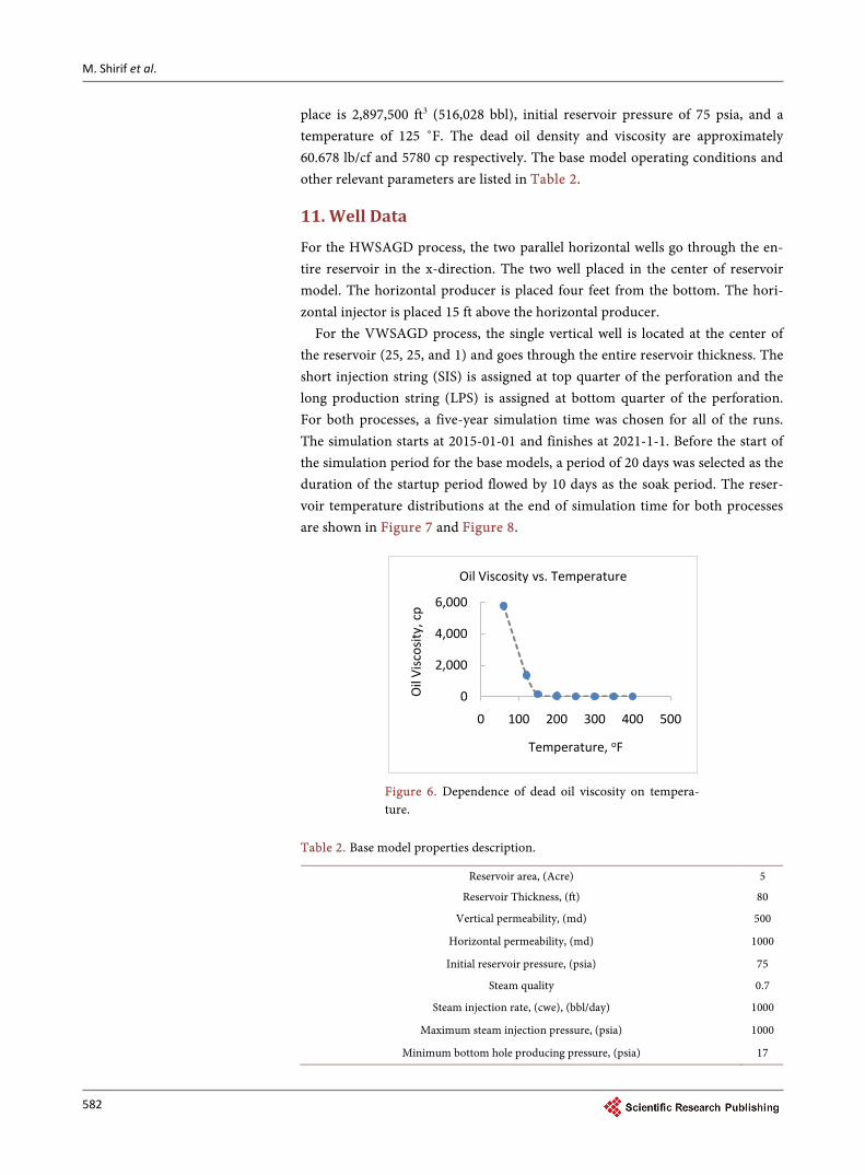
place is 2,897,500 ft3 (516,028 bbl), initial reservoir pressure of 75 psia, and a temperature of 125 ˚F. The dead oil density and viscosity are approximately 60.678 lb/cf and 5780 cp respectively. The base model operating conditions and other relevant parameters are listed in Table 2.
11. Well Data
For the HWSAGD process, the two parallel horizontal wells go through the en-tire reservoir in the x-direction. The two well placed in the center of reservoir model. The horizontal producer is placed four feet from the bottom. The hori-zontal injector is placed 15 ft above the horizontal producer.
For the VWSAGD process, the single vertical well is located at the center of the reservoir (25, 25, and 1) and goes through the entire reservoir thickness. The short injection string (SIS) is assigned at top quarter of the perforation and the long production string (LPS) is assigned at bottom quarter of the perforation. For both processes, a five-year simulation time was chosen for all of the runs. The simulation starts at 2015-01-01 and finishes at 2021-1-1. Before the start of the simulation period for the base models, a period of 20 days was selected as the duration of the startup period flowed by 10 days as the soak period. The reser-voir temperature distributions at the end of simulation time for both processes are shown in Figure 7 and Figure 8.
Figure 6. Dependence of dead oil viscosity on tempera-ture.
Table 2. Base model properties description.
Reservoir area, (Acre) 5
Reservoir Thickness, (ft) 80
Vertical permeability, (md) 500
Horizontal permeability, (md) 1000
Initial reservoir pressure, (psia) 75
Steam quality 0.7
Steam injection rate, (cwe), (bbl/day) 1000
Maximum steam injection pressure, (psia) 1000
Minimum bottom hole producing pressure, (psia) 17
0
2,000
4,000
6,000
0 100 200 300 400 500
Oil
Visc
osity
, cp
Temperature, oF
Oil Viscosity vs. Temperature

M. Shirif et al.
583
Figure 7. VWSAGD temperature distribution at end of simulation time.
Figure 8. HWSAGD temperature distribution at end of simulation time.
12. Results and Discussion
In this study, the newly developed vertical Well SAGD process has been opti-mized and tested. The results from this process were compared to the conven-tional SAGD process, which uses horizontal wells. A sensitivity study was con-ducted to study the effect of the vertical permeability, reservoir area size, reser-

M. Shirif et al.
584
voir thickness, steam injection rate, steam quality, producing bottom hole flow-ing pressure, and the steam injection pressure. In addition, a comparison be-tween the VWSAGD and conventional HWSAGD processes was made.
Optimization of the Grid Density When dealing with numerical reservoir simulators, special attention must be
given to the number of grid blocks used to simulate the entire reservoir. A small number of reservoir grids will result in a higher truncation error. A higher number of reservoir grids will cause a decrease in the truncation error, and at the same time, the round off error will increase. In the commercial simulator used for this study, there was an option to choose the method of solution of the finite difference equation using iterative techniques (round off error will not accumu-late). For this study, we selected and simulated five grid sizes. Based on the si-mulation results, it is clear that the optimum grid size is 49 × 49 × 20.
Optimization of Reservoir Perforation For the base run in this study, the reservoir thickness was selected to be 80 ft,
and the question posed was what is the optimum perforation zone for the short injection string, and the long production string. In order for us to optimize the perforation of the two strings, 23 simulation runs were conducted to calculate the optimum intervals, which will give us the lowest steam oil ratio, lowest water oil ratio and maximum cumulative oil recovery. Based on the simulation results of this study, it has been found that perforating the top quarter of the reservoir for the short injection string, and the bottom quarter of the reservoir for the long production string were the optimum perforations.
Comparison of VWSAGD and HWSAGD Steam Assisted Gravity Drainage using horizontal wells is an extremely ex-
pensive process to implement due to the high cost of drilling two horizontal wells as the operating cost associated with this process. In contrast, the newly developed vertical well SAGD process requires only a single vertical well and is inexpensive to drill, and a low operation cost compared as compared to hori-zontal wells. Based on a literature review, the cost of drilling an operating hori-zontal well is 5 - 6 times more expensive than a vertical well, and sometimes it costs more if the horizontal well increases in length. In order for us to compare the productivity of the two processes, we have made a very conservative assump-tion that the cost of drilling and operating a horizontal is equal to two vertical wells. This means drilling a pair of horizontal wells for conventional SAGD is equivalent to developing the same reservoir with four vertical wells. Each area pattern must be divided into four equal sections, and each quarter section will be developed by a single vertical SAGD well. For the well operating conditions, the steam injection rate must be reduced by one quarter for each section. The total production of the entire drainage area will equal to four times the production of a quarter section. This allows us to only simulate quarter sections of the reser-voir by a single vertical well, and is then compared to horizontal well SAGD. Figures 9-20 show the production history for one single quarter section area developed by vertical well SAGD. Figure 9 shows the cumulative recovery as a

M. Shirif et al.
585
Figure 9. Effect of quarter section areas on cumulative oil recovery for VWSAGD process.
Figure 10. Effect of quarter section areas on oil production rate for VWSAGD process.
Figure 11. Effect of quarter section areas on recovery factor for VWSAGD process.
0
20,000
40,000
60,000
80,000
100,000
0 500 1000 1500 2000 2500
Cum
ulat
ive
Oil,
bbl
Injection Time, days
VWSAGD [A/4]: Effect of Reservoir Area Size on Cumulative Oil Recovery
A = 2.5 Acre
A = 5 Acre
A = 7.5 Acre
A = 1.25 Acre
0
20
40
60
80
100
120
0 500 1000 1500 2000 2500
Oil
Rate
, bb
l/day
Injection Time, days
VWSAGD [A/4]: Effect of Reservoir Area Size on Oil Production Rate
A = 2.5 Acre
A = 5 Acre
A = 7.5 Acre
05
10152025303540
0 500 1000 1500 2000 2500
Reco
very
Fac
tor,
%
Injection Time, days
VWSAGD [A/4]: Effect of Reservoir Area Size on Recovery Factor
A = 2.5 Acre
A = 5 Acre
A = 7.5 Acre

M. Shirif et al.
586
function of the quarter section area. It is clear that as the area increases, the cu-mulative recovery decreases. This is due to the fact that a limited steam injection will heat up the entire small area of the reservoir and a result; this will produce a higher oil recovery. This conclusion is also supported by the results presented in Figures 10-13. The smallest section area (2.5 acres) gave the highest oil rate, lowest steam oil ratio, lowest water oil ratio, and the highest oil recovery. If we examine the cumulative oil recovery in Figure 9, the section area (1.25 acres) gave the lowest oil recovery, which contradicts the conclusion made earlier. The justification for this low recovery is shown in Figure 14. The smallest area (1.25 acres) was unable to sustain an injection rate of 250 bbl/day of steam. Mean-while, the other three areas (2.55 acres, 7.5 acres) showed no problem of sus-taining a steam injection rate of 250 bbl/day. The smallest received only 25% of the amount of steam injected compared to the other three areas. This is the rea-son why this area gave the smallest recovery. Figure 15 shows that the average pressure for the smallest area was the highest, and Figure 16 shows the average
Figure 12. Effect of quarter section areas on steam oil ratio vertical well SAGD process.
Figure 13. Effect of quarter section areas on water oil ratio for VWSAGD process.
0
2
4
6
8
10
12
14
0 500 1000 1500 2000 2500
Stea
m O
il Ra
tio, b
bl/b
bl
Injection Time, days
VWSAGD [A/4]: Effect of Reservoir Area Size on SOR
A = 7.5 Acre
A = 5 Acre
A = 2.5 Acre
0
5
10
15
20
25
0 500 1000 1500 2000 2500
Wat
er O
il Ra
tio, b
bl/b
bl
Injection Time, days
VWSAGD [A/4]: Effect of Reservoir Area Size on WOR
A = 7.5 Acre
A = 5 Acre
A = 2.5 Acre

M. Shirif et al.
587
Figure 14. Effect of quarter section areas on steam injection rate for VWSAGD process.
Figure 15. Effect of quarter section areas on average reservoir pressure for VWSAGD process.
Figure 16. Effect of quarter section areas on reservoir temperature for VWSAGD process.
0
50
100
150
200
250
300
0 500 1000 1500 2000 2500
Inje
ctio
n Ra
te, b
bl/d
ay
Injection Time, days
VWSAGD [A/4]: Effect of Reservoir Area Size on Steam Injection Rate
A = 7.5 Acre
A = 5 Acre
A = 2.5 Acre
A = 1.25 Acre
0
50
100
150
200
250
300
0 500 1000 1500 2000 2500
Aver
age
Rese
rvoi
r Pre
ssur
e, p
si
Injection Time, days
VWSAGD [A/4]: Effect of Reservoir Area Size on Average Reservoir Pressure
A = 2.5 Acre
A = 5 Acre
A = 7.5 Acre
050
100150200250300350
0 500 1000 1500 2000 2500
Rese
rvoi
r Tem
pera
ture
, oF
Injection Time, days
VWSAGD [A/4]: Effect of Reservoir Area Size on Average Reservoir Temperature
A = 2.5 Acre
A = 5 Acre
A = 7.5 Acre

M. Shirif et al.
588
temperature was the highest for the smallest area. These two results support the previous finding. Figure 17 shows the effect of quarter section areas on cumula-tive liquid production for VWSAGD process.
Figure 18 shows the effect of the area size on the cumulative oil recovery produced by the four vertical well SAGD process. The results obtained for the single vertical well were multiplied by four. To show the comparison between the newly developed process and the conventional SAGD process, the results are shown in Figure 19 and Figure 20. In Figure 19, the effect of reservoir thickness on the cumulative oil recovery when produced by single vertical well SAGD, four vertical well SAGD, and the paired horizontal well SAGD. The results show that the four vertical well SAGD outperformed the horizontal pair SAGD by a large amount. When the area reached 30 acres, both of these processes gave the same results. Figure 20 shows the effect of the reservoir area on the cumulative oil recovery produced by the three processes. The results show that as the area
Figure 17. Effect of quarter section areas on cumulative liquid production for VWSAGD process.
Figure 18. Total cumulative oil recovery from 4 vertical wells for VWSAGD process.
0
200,000
400,000
600,000
800,000
1,000,000
0 500 1000 1500 2000 2500
Cum
ulat
ive
Liqu
id, b
bl
Injection Time, days
VWSAGD [A/4]: Effect of Reservoir Area Size on Cumulative Liquid Production
A = 2.5 Acre
A = 5 Acre
A = 7.5 Acre
050,000
100,000150,000200,000250,000300,000350,000400,000
0 500 1000 1500 2000 2500
Cum
ulat
ive
Oil,
bbl
Injection Time, days
VWSAGD [4VW]: Effect of Reservoir Area Size on Cumulative Oil Recovery
A = 10 Acre
A = 20 Acre
A = 30 Acre
A = 5 Acre

M. Shirif et al.
589
Figure 19. Effect of reservoir thickness on oil recovery for HWSAGD and VWSAGD processes.
Figure 20. Effect of reservoir area on oil recovery for HWSAGD and VWSAGD process.
increases, the four vertical well SAGD and the horizontal well SAGD gave the same recovery when the area was equal to 30 acres. The results in Figure 20 also showed that the optimum area, which gave the highest recovery for four vertical well SAGD, was 10 acres.
13. Conclusions
Based on this research study, we can conclude the following: 1) A new process (VWSAGD) for steam assisted gravity drainage utilizing
vertical wells has been presented. The process was optimized and tested. This new process has shown very promising results.
2) As the reservoir thickness increases, the new process is more suitable and gives better results.
3) As the reservoir vertical permeability decreases, the vertical well SAGD is more shown better oil recovery.
050,000
100,000150,000200,000250,000300,000350,000400,000
0 40 80 120 160 200
Cum
ulat
ive
Oil
Prod
uctio
n, b
bl
Reservoir Thickness, ft
Effect of Reservoir Thicknessat One PV of Steam Injection
4 VWSAGD
HWSAGD
VWSAGD
0
30,000
60,000
90,000
120,000
150,000
180,000
0 5 10 15 20 25 30 35
Cum
ulat
ive
Oil
Prod
uctio
n, b
bl
Reservoir Area, Acre
Effect of Reservoir Area at One PV of Steam Injection
VWSAGD
HWSAGD
4 VWSAGD
2 VWSAGD

M. Shirif et al.
590
Acknowledgements
The authors gratefully acknowledge the unlimited financial support of the Fa-culty of Graduate Studies and Research at the University of Regina.
References [1] Butler, R.M. (1991) Thermal Recovery of Oil and Bitumen. Prentice Hall Publishing
Company, New Jersey.
[2] Butler, R.M. and Stephens, D.J. (1981) The Gravity Drainage on Steam Heated Heavy Oil to Parallel Horizontal Wells. Journal of Canadian Petroleum Technology, 20, 90-96. https://doi.org/10.2118/81-02-07
[3] Sawhney, G.S., Liebe, H. and Butler, R.M. (1995) Vertical Injection Wells for SAGD: A Practical Option or Not. Journal of Canadian Petroleum Technology, 34, 9 p. https://doi.org/10.2118/95-01-06
[4] Butler, R.M. (1985) A New Approach to the Modelling of Steam Assisted Gravity Drainage. Journal of Canadian Petroleum Technology, 24, 11 p. https://doi.org/10.2118/85-03-01
[5] Sugianto, S. and Butler, R.M. (1990) The Production of Conventional Heavy Oil Reservoirs with Bottom Water Using Steam Assisted Gravity Drainage.
[6] Butler, R.M. (1998) SAGD Comes of AGE. Journal of Canadian Petroleum Tech-nology, 37, 4 p. https://doi.org/10.2118/98-07-da
Submit or recommend next manuscript to SCIRP and we will provide best service for you:
Accepting pre-submission inquiries through Email, Facebook, LinkedIn, Twitter, etc. A wide selection of journals (inclusive of 9 subjects, more than 200 journals) Providing 24-hour high-quality service User-friendly online submission system Fair and swift peer-review system Efficient typesetting and proofreading procedure Display of the result of downloads and visits, as well as the number of cited articles Maximum dissemination of your research work
Submit your manuscript at: http://papersubmission.scirp.org/ Or contact [email protected]